EP3081783B1 - Collecteur de combustible à couplage thermique - Google Patents
Collecteur de combustible à couplage thermique Download PDFInfo
- Publication number
- EP3081783B1 EP3081783B1 EP16165043.7A EP16165043A EP3081783B1 EP 3081783 B1 EP3081783 B1 EP 3081783B1 EP 16165043 A EP16165043 A EP 16165043A EP 3081783 B1 EP3081783 B1 EP 3081783B1
- Authority
- EP
- European Patent Office
- Prior art keywords
- fuel
- manifold
- pilot
- passage
- main
- Prior art date
- Legal status (The legal status is an assumption and is not a legal conclusion. Google has not performed a legal analysis and makes no representation as to the accuracy of the status listed.)
- Active
Links
Images

Classifications
-
- F—MECHANICAL ENGINEERING; LIGHTING; HEATING; WEAPONS; BLASTING
- F23—COMBUSTION APPARATUS; COMBUSTION PROCESSES
- F23R—GENERATING COMBUSTION PRODUCTS OF HIGH PRESSURE OR HIGH VELOCITY, e.g. GAS-TURBINE COMBUSTION CHAMBERS
- F23R3/00—Continuous combustion chambers using liquid or gaseous fuel
- F23R3/28—Continuous combustion chambers using liquid or gaseous fuel characterised by the fuel supply
-
- F—MECHANICAL ENGINEERING; LIGHTING; HEATING; WEAPONS; BLASTING
- F02—COMBUSTION ENGINES; HOT-GAS OR COMBUSTION-PRODUCT ENGINE PLANTS
- F02C—GAS-TURBINE PLANTS; AIR INTAKES FOR JET-PROPULSION PLANTS; CONTROLLING FUEL SUPPLY IN AIR-BREATHING JET-PROPULSION PLANTS
- F02C7/00—Features, components parts, details or accessories, not provided for in, or of interest apart form groups F02C1/00 - F02C6/00; Air intakes for jet-propulsion plants
- F02C7/22—Fuel supply systems
- F02C7/222—Fuel flow conduits, e.g. manifolds
-
- F—MECHANICAL ENGINEERING; LIGHTING; HEATING; WEAPONS; BLASTING
- F23—COMBUSTION APPARATUS; COMBUSTION PROCESSES
- F23R—GENERATING COMBUSTION PRODUCTS OF HIGH PRESSURE OR HIGH VELOCITY, e.g. GAS-TURBINE COMBUSTION CHAMBERS
- F23R3/00—Continuous combustion chambers using liquid or gaseous fuel
- F23R3/28—Continuous combustion chambers using liquid or gaseous fuel characterised by the fuel supply
- F23R3/34—Feeding into different combustion zones
- F23R3/343—Pilot flames, i.e. fuel nozzles or injectors using only a very small proportion of the total fuel to insure continuous combustion
-
- B—PERFORMING OPERATIONS; TRANSPORTING
- B23—MACHINE TOOLS; METAL-WORKING NOT OTHERWISE PROVIDED FOR
- B23P—METAL-WORKING NOT OTHERWISE PROVIDED FOR; COMBINED OPERATIONS; UNIVERSAL MACHINE TOOLS
- B23P15/00—Making specific metal objects by operations not covered by a single other subclass or a group in this subclass
-
- F—MECHANICAL ENGINEERING; LIGHTING; HEATING; WEAPONS; BLASTING
- F02—COMBUSTION ENGINES; HOT-GAS OR COMBUSTION-PRODUCT ENGINE PLANTS
- F02C—GAS-TURBINE PLANTS; AIR INTAKES FOR JET-PROPULSION PLANTS; CONTROLLING FUEL SUPPLY IN AIR-BREATHING JET-PROPULSION PLANTS
- F02C7/00—Features, components parts, details or accessories, not provided for in, or of interest apart form groups F02C1/00 - F02C6/00; Air intakes for jet-propulsion plants
- F02C7/22—Fuel supply systems
- F02C7/224—Heating fuel before feeding to the burner
-
- F—MECHANICAL ENGINEERING; LIGHTING; HEATING; WEAPONS; BLASTING
- F02—COMBUSTION ENGINES; HOT-GAS OR COMBUSTION-PRODUCT ENGINE PLANTS
- F02C—GAS-TURBINE PLANTS; AIR INTAKES FOR JET-PROPULSION PLANTS; CONTROLLING FUEL SUPPLY IN AIR-BREATHING JET-PROPULSION PLANTS
- F02C7/00—Features, components parts, details or accessories, not provided for in, or of interest apart form groups F02C1/00 - F02C6/00; Air intakes for jet-propulsion plants
- F02C7/22—Fuel supply systems
- F02C7/228—Dividing fuel between various burners
-
- F—MECHANICAL ENGINEERING; LIGHTING; HEATING; WEAPONS; BLASTING
- F02—COMBUSTION ENGINES; HOT-GAS OR COMBUSTION-PRODUCT ENGINE PLANTS
- F02C—GAS-TURBINE PLANTS; AIR INTAKES FOR JET-PROPULSION PLANTS; CONTROLLING FUEL SUPPLY IN AIR-BREATHING JET-PROPULSION PLANTS
- F02C9/00—Controlling gas-turbine plants; Controlling fuel supply in air- breathing jet-propulsion plants
- F02C9/26—Control of fuel supply
- F02C9/32—Control of fuel supply characterised by throttling of fuel
- F02C9/34—Joint control of separate flows to main and auxiliary burners
-
- F—MECHANICAL ENGINEERING; LIGHTING; HEATING; WEAPONS; BLASTING
- F05—INDEXING SCHEMES RELATING TO ENGINES OR PUMPS IN VARIOUS SUBCLASSES OF CLASSES F01-F04
- F05D—INDEXING SCHEME FOR ASPECTS RELATING TO NON-POSITIVE-DISPLACEMENT MACHINES OR ENGINES, GAS-TURBINES OR JET-PROPULSION PLANTS
- F05D2230/00—Manufacture
- F05D2230/30—Manufacture with deposition of material
- F05D2230/31—Layer deposition
-
- F—MECHANICAL ENGINEERING; LIGHTING; HEATING; WEAPONS; BLASTING
- F05—INDEXING SCHEMES RELATING TO ENGINES OR PUMPS IN VARIOUS SUBCLASSES OF CLASSES F01-F04
- F05D—INDEXING SCHEME FOR ASPECTS RELATING TO NON-POSITIVE-DISPLACEMENT MACHINES OR ENGINES, GAS-TURBINES OR JET-PROPULSION PLANTS
- F05D2230/00—Manufacture
- F05D2230/50—Building or constructing in particular ways
- F05D2230/53—Building or constructing in particular ways by integrally manufacturing a component, e.g. by milling from a billet or one piece construction
-
- F—MECHANICAL ENGINEERING; LIGHTING; HEATING; WEAPONS; BLASTING
- F05—INDEXING SCHEMES RELATING TO ENGINES OR PUMPS IN VARIOUS SUBCLASSES OF CLASSES F01-F04
- F05D—INDEXING SCHEME FOR ASPECTS RELATING TO NON-POSITIVE-DISPLACEMENT MACHINES OR ENGINES, GAS-TURBINES OR JET-PROPULSION PLANTS
- F05D2230/00—Manufacture
- F05D2230/60—Assembly methods
- F05D2230/64—Assembly methods using positioning or alignment devices for aligning or centring, e.g. pins
- F05D2230/642—Assembly methods using positioning or alignment devices for aligning or centring, e.g. pins using maintaining alignment while permitting differential dilatation
-
- F—MECHANICAL ENGINEERING; LIGHTING; HEATING; WEAPONS; BLASTING
- F05—INDEXING SCHEMES RELATING TO ENGINES OR PUMPS IN VARIOUS SUBCLASSES OF CLASSES F01-F04
- F05D—INDEXING SCHEME FOR ASPECTS RELATING TO NON-POSITIVE-DISPLACEMENT MACHINES OR ENGINES, GAS-TURBINES OR JET-PROPULSION PLANTS
- F05D2260/00—Function
- F05D2260/20—Heat transfer, e.g. cooling
-
- F—MECHANICAL ENGINEERING; LIGHTING; HEATING; WEAPONS; BLASTING
- F05—INDEXING SCHEMES RELATING TO ENGINES OR PUMPS IN VARIOUS SUBCLASSES OF CLASSES F01-F04
- F05D—INDEXING SCHEME FOR ASPECTS RELATING TO NON-POSITIVE-DISPLACEMENT MACHINES OR ENGINES, GAS-TURBINES OR JET-PROPULSION PLANTS
- F05D2270/00—Control
- F05D2270/30—Control parameters, e.g. input parameters
- F05D2270/31—Fuel schedule for stage combustors
-
- F—MECHANICAL ENGINEERING; LIGHTING; HEATING; WEAPONS; BLASTING
- F05—INDEXING SCHEMES RELATING TO ENGINES OR PUMPS IN VARIOUS SUBCLASSES OF CLASSES F01-F04
- F05D—INDEXING SCHEME FOR ASPECTS RELATING TO NON-POSITIVE-DISPLACEMENT MACHINES OR ENGINES, GAS-TURBINES OR JET-PROPULSION PLANTS
- F05D2300/00—Materials; Properties thereof
- F05D2300/50—Intrinsic material properties or characteristics
- F05D2300/502—Thermal properties
- F05D2300/5021—Expansivity
- F05D2300/50212—Expansivity dissimilar
-
- F—MECHANICAL ENGINEERING; LIGHTING; HEATING; WEAPONS; BLASTING
- F16—ENGINEERING ELEMENTS AND UNITS; GENERAL MEASURES FOR PRODUCING AND MAINTAINING EFFECTIVE FUNCTIONING OF MACHINES OR INSTALLATIONS; THERMAL INSULATION IN GENERAL
- F16L—PIPES; JOINTS OR FITTINGS FOR PIPES; SUPPORTS FOR PIPES, CABLES OR PROTECTIVE TUBING; MEANS FOR THERMAL INSULATION IN GENERAL
- F16L39/00—Joints or fittings for double-walled or multi-channel pipes or pipe assemblies
-
- F—MECHANICAL ENGINEERING; LIGHTING; HEATING; WEAPONS; BLASTING
- F16—ENGINEERING ELEMENTS AND UNITS; GENERAL MEASURES FOR PRODUCING AND MAINTAINING EFFECTIVE FUNCTIONING OF MACHINES OR INSTALLATIONS; THERMAL INSULATION IN GENERAL
- F16L—PIPES; JOINTS OR FITTINGS FOR PIPES; SUPPORTS FOR PIPES, CABLES OR PROTECTIVE TUBING; MEANS FOR THERMAL INSULATION IN GENERAL
- F16L9/00—Rigid pipes
- F16L9/18—Double-walled pipes; Multi-channel pipes or pipe assemblies
- F16L9/19—Multi-channel pipes or pipe assemblies
-
- Y—GENERAL TAGGING OF NEW TECHNOLOGICAL DEVELOPMENTS; GENERAL TAGGING OF CROSS-SECTIONAL TECHNOLOGIES SPANNING OVER SEVERAL SECTIONS OF THE IPC; TECHNICAL SUBJECTS COVERED BY FORMER USPC CROSS-REFERENCE ART COLLECTIONS [XRACs] AND DIGESTS
- Y02—TECHNOLOGIES OR APPLICATIONS FOR MITIGATION OR ADAPTATION AGAINST CLIMATE CHANGE
- Y02T—CLIMATE CHANGE MITIGATION TECHNOLOGIES RELATED TO TRANSPORTATION
- Y02T50/00—Aeronautics or air transport
- Y02T50/60—Efficient propulsion technologies, e.g. for aircraft
Definitions
- This invention relates generally to fluid manifolds, and more particularly to fuel manifolds in gas turbine engines.
- a gas turbine engine includes a turbomachinery core having a high pressure compressor, a combustor, and a high pressure turbine in serial flow relationship.
- the core is operable in a known manner to generate a primary gas flow.
- the core may be combined with a fan and low pressure turbine system to generate propulsive thrust, or with a work turbine to extract mechanical energy and turn a driveshaft or propeller.
- fuel is introduced to the combustor through an array of fuel nozzles which are coupled to an annular external manifold surrounding the combustor and mounted to a combustor case.
- pressurized fuel is fed to the manifold.
- the manifold then distributes the pressurized fuel to the individual fuel nozzles through individual feed lines.
- Such manifolds are commonly manufactured from various tubes and fittings, and are secured to the combustor with brackets and other mounting hardware.
- Aircraft engine fuel manifolds are in a harsh environment and are located relatively close to the combustor case.
- the combustor case grows as the engine warms, but the temperature of the fuel in the manifold stays relatively cool. This temperature difference, coupled with the different material growth rates of various components, creates a thermal loading on the manifold.
- the length of piping between mounting points i.e. the nozzle-to-nozzle distance
- staged fuel delivery systems which include two or more fuel circuits used during different engine operating conditions (e.g., pilot and main circuits).
- each circuit or stage requires separate piping and connections, increasing weight, complexity, and parts count.
- the fuel passages within the manifold and other piping are subject to undesirable carbon buildup ("coking") of the residual fuel during periods of time when fuel is not flowing in a particular circuit.
- US 2012/145247 describes a flexible hose assembly having a flexible tube for conveying fuel through a first fuel passage formed interiorly of the flexible tube and a flexible hose surrounding the flexible tube and forming therewith a second fuel passage.
- the flexible tube provides internal support for the flexible hose while also allowing for flow of fuel through the second fuel passage and the fuel passages are separate from one another along a length of the flexible hose assembly.
- fuel flowing through the other of the fuel passages acts to cool the fuel passage in the low flow or no flow condition to prevent stagnant fuel in the passage from heating up and coking.
- US 2010/050645 discloses a fuel distribution manifold system for a gas turbine engine that includes a plurality of interconnected manifold segments, each manifold segment extending between a pair of fittings, each manifold segment including at least one fuel transfer tube and a sealing tube that surrounds the at least one fuel transfer tube, wherein opposed end portions of the at least one fuel transfer tube are dynamically connected to the fittings and opposed end portions of the sealing tube are statically connected to the fittings.
- WO 2009/126485 describes a method of assembling a fuel nozzle comprising the steps of forming a pilot assembly; coupling the pilot assembly to a unitary distributor such that the pilot assembly is in flow communication with a pilot flow passage in the unitary distributor; coupling a unitary swirler having an adaptor to the unitary distributor; coupling the adaptor to a stem housing; coupling the unitary distributor to the stem housing; and coupling a centerbody to the stem housing.
- a fuel manifold apparatus includes: an annular array of fuel nozzles interconnected by a plurality of manifold tubes, wherein each manifold tube includes at least two fuel passages integrally formed therein, the fuel passages being configured for conduction heat transfer therebetween.
- each manifold tube is a monolithic component formed using an additive manufacturing process.
- each manifold tube includes: a pilot primary fuel passage; a pilot secondary fuel passage; and a main fuel passage.
- each fuel nozzle includes: a pilot primary fuel circuit and a pilot primary fuel nozzle connected in fluid communication with the pilot primary fuel passage; a pilot secondary fuel circuit and a pilot secondary fuel nozzle connected in fluid communication with the pilot secondary fuel passage; and a main fuel circuit and a main fuel ring connected in fluid communication with the main fuel passage.
- the apparatus further includes: a fuel system operable to supply a flow of liquid fuel at varying flowrates; a pilot primary fuel conduit coupled between the fuel system and the pilot primary fuel passages; a pilot secondary fuel conduit coupled between the fuel system and the pilot secondary fuel passages; and a main fuel conduit coupled between the fuel system and the main fuel passages.
- the main fuel passage is centrally located within a cross-sectional shape of the manifold tube; the pilot primary fuel passage is arcuate and disposed concentrically with the main fuel passage; and the pilot secondary fuel passage is arcuate and disposed concentrically with the main fuel passage.
- each manifold tube includes a tube segment with an end flange disposed at first and second ends thereof.
- each fuel nozzle is coupled to a valve housing which includes a coupling flange; and each coupling flange is connected to the end flanges of two adjacent ones of the manifold tubes.
- each valve housing includes: the coupling flange; a mounting flange disposed perpendicular to the coupling flange; and at least one lobe disposed between the coupling flange and the mounting flange.
- the at least one lobe includes a splitter valve disposed therein.
- the valve housing is a monolithic component formed using an additive manufacturing process.
- each manifold tube connects alternate ones of the fuel nozzles.
- the manifold is configured as first and second rings of manifold tubes; the first ring interconnects a first group of the fuel nozzles; the second ring interconnects a second group of the fuel nozzles; and wherein the fuel nozzles of the first group alternate with the fuel nozzles of the second group.
- the manifold tubes of the first ring are interlaced with the manifold tubes of the second ring.
- a rotary machine includes: a compressor, a combustor, and a turbine arranged in serial flow communication and operable to generate a core flow; and a fuel manifold, including: an annular array of fuel nozzles communicating with the combustor, the fuel nozzles interconnected by a plurality of manifold tubes, wherein each manifold tube includes at least two fuel passages integrally formed therein, the fuel passages being configured for conduction heat transfer therebetween.
- the rotary machine further includes a second turbine arranged to extract energy from the core flow and to drive a fan.
- a method of assembling a fuel manifold includes: positioning an annular array of fuel nozzles in communication with a combustor; and interconnecting the fuel nozzles using a plurality of manifold tubes, wherein each manifold tube includes at least two fuel passages integrally formed therein, the fuel passages being configured for conduction heat transfer therebetween.
- each manifold tube includes a pilot primary fuel passage, a pilot secondary fuel passage, and a main fuel passage; and each fuel nozzle includes: a pilot primary fuel circuit communicating with a pilot primary fuel nozzle, a pilot secondary fuel circuit communicating with a pilot secondary fuel nozzle, and a main fuel circuit communicating with a main fuel ring; the method further including connecting the fuel circuits of the fuel nozzles in fluid communication with the respective fuel passages of the manifold tubes.
- each fuel nozzle is coupled to a valve housing which includes a coupling flange, the method further comprising connecting each coupling flange to end flanges of two adjacent ones of the manifold tubes.
- each manifold tube is a monolithic component formed using an additive manufacturing process.
- FIG. 1 depicts an exemplary gas turbine engine 10 having in serial flow communication a fan 12, an optional low pressure compressor or “booster” 14 and a low pressure turbine (“LPT") 16 collectively referred to as a “low pressure system”, and a high pressure compressor ("HPC") 18, a combustor 20, and a high pressure turbine (“HPT”) 22, arranged in serial flow communication and collectively referred to as a "gas generator", "core”, or "high pressure system”.
- the HPT 22 drives the HPC 18 through a mechanical connection such as a shaft
- the LPT 16 drives the fan 12 and booster 14 (if present) through a mechanical connection such as a shaft.
- the high pressure system is operable in a known manner to generate a primary or core flow.
- the low pressure system is operable in a known manner to extract energy from the core flow and generate a fan flow or bypass flow. While the illustrated engine 10 is a high-bypass turbofan engine, the principles described herein are equally applicable to turboprop, turbojet, and turboshaft engines, as well as turbine engines used for other vehicles or in stationary applications.
- the combustor 20 includes a radial array of fuel nozzles 24 which are coupled to a fuel manifold 26 surrounding the combustor 20.
- the fuel manifold 26 includes a plurality of valve housings 28, each of which is coupled to one of the fuel nozzles 24 and which may be integral with the corresponding fuel nozzle 24.
- the valve housings 28 are mounted to the combustor casing 30, in an annular array.
- the valve housings 28 (and thus the fuel nozzles 24) are interconnected by a plurality of manifold tubes 32.
- each valve housing 28 includes a mounting flange 34 with a pattern of bolt holes 36 formed therein for securing the mounting flange 34 to the combustor casing 30, a coupling flange 38 oriented perpendicular to the mounting flange 34, and one or more lobes 40 joining the mounting flange 34 and the coupling flange 38.
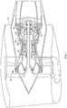
- Each fuel nozzle 24 (see FIG. 3 ) includes a stem 42 extending radially inward from the mounting flange 34 and terminating at a nozzle tip 44 at its inboard end.
- the nozzle tip 44 includes a pilot fuel injector 48 with a pilot primary nozzle 50 and a pilot secondary nozzle 52.
- the nozzle tip 44 also includes an annular main fuel ring 54 with an array of main fuel orifices 56 around its periphery.
- valve housing 28 and fuel nozzle 24 may incorporate two or more fuel circuits therein.
- each circuit is represented schematically by a single dashed line, with the understanding that each line may represent one or more discreet pipes or tubes, or one or more internal fuel passages formed integrally with the valve housing 28 and/or the fuel nozzle 24.
- a pilot primary fuel circuit 58 extends from a pilot primary fuel port 60 formed in the coupling flange 38, through the stem 42, to the pilot primary nozzle 50.
- a pilot secondary fuel circuit 62 extends from a pilot secondary fuel port 64 formed in the coupling flange 38, to a pilot secondary splitter valve 66 disposed in one of the lobes 40, through the stem 42, to the pilot secondary nozzle 52.
- the pilot secondary splitter valve 66 is operable to permit flow to the fuel nozzle 24 but block flow the opposite direction, and may be, for example, a pressure-operated valve.
- a main fuel circuit 68 extends from a main fuel port 70 formed in the coupling flange 38, to a main splitter valve 72 disposed in one of the lobes 40, through the stem 42, to the main fuel ring 54.
- the main splitter valve 72 is operable to permit flow to the fuel nozzle 24 but block flow the opposite direction, and may be, for example, a pressure-operated valve.
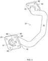
- FIG. 4 depicts one of the manifold tubes 32.
- the manifold tube 32 includes a tube segment 74 having first and second ends 76, 78, with an end flange 80 disposed at each end.
- Each end flange 80 includes a pattern of bolt holes 82 formed therein matching the bolt holes in the coupling flange 38.
- the tube segment 74 may have one or more bends formed therein to suit a specific application.
- the manifold tube 32 contains multiple interior passages. Each passage runs from the first end 76 to the second end 78.
- the manifold tube 32 includes a centrally-located main fuel passage 84 with a circular cross-section shape.
- An arcuate pilot secondary fuel passage 86 is disposed concentrically with the main fuel passage 84.
- An arcuate pilot primary fuel passage 88 is also disposed concentrically with the main fuel passage 84.
- the cross-sectional area of the pilot fuel passages 86, 88 are sized in proportion to the relative fuel flow rates therethrough.
- the pilot secondary fuel passage 86 extends over approximately 3/4 of a circle, while the pilot primary fuel passage 88 extends over less than approximately 1/4 of a circle.
- the cross-sectional shape of the pilot secondary fuel passage 86 incorporates a small radially-extending strut 87 which provides mechanical support. This could take the form of a single continuous rib, or an array of short pins or ribs along the length of the manifold tube 32.
- the cross-sectional pattern may extend prismatically through the manifold tube 32, or it may extend along a spiral or helical path.
- pilot fuel passages 86, 88 are thermally coupled with the main fuel passage 84. More specifically, the pilot fuel passages 86, 88 are separated from the main fuel passage 84 by a single wall thickness which readily permits conduction heat transfer from the main fuel passage 84 to the pilot fuel passages 86, 88. This will be effective to reduce or prevent coking of fuel in the main fuel passage 84 during conditions when fuel is not flowing therein.
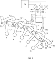
- valve housings 28 are arranged in annular form around the combustor casing 30 (only a portion of the full circle is shown in FIG. 2 ).
- the valve housings 28 are interconnected by a plurality of the manifold tubes 32.
- each coupling flange 38 is clamped between the end flanges 80 of two adjacent manifold tubes 32, for example using fasteners such as the illustrated bolts 90.
- Each of the fuel passages in the manifold tube 32 mates with the corresponding ports in the coupling flange 38.
- a continuous fluid flow path is defined for the passages 84, 86, and 88 in the manifold tubes 32 .
- the fuel manifold 26 includes two rings 92 and 94.
- each manifold tube 32 connects two valve housings 28 that are separated by an intervening valve housing 28.
- alternate ones of the valve housings 28 (and thus alternate ones of the fuel nozzles 24) are connected by a manifold tube 32 for each ring 92, 94.
- This configuration makes the length of the manifold tube 32 independent from the distance between two adjacent valve housings 28. It is also possible that each manifold tube 32 could span a greater distance, for example connecting every third or fourth valve housing 28. In FIG.
- valve housings 28, marked "A”, belong to the first ring 92
- the other half of the valve housings 28, marked "B” belong to the second ring 94.
- the first and second rings 92, 94 are interlaced or intertwined with each other, the manifold tubes 32 being shaped to facilitate this configuration.
- the fuel manifold 26 is connected to a fuel system 96 of a known type, operable to supply a flow of liquid fuel at varying flowrates according to operational need.
- the fuel system 96 supplies fuel to a pilot primary control valve 98 which is coupled to a pilot primary fuel conduit 100, which in turn supplies fuel to the pilot primary fuel passages 88 and ultimately to the pilot primary circuits 58.
- the fuel system 96 also supplies fuel to a pilot secondary fuel control valve 102 which is coupled to a pilot secondary conduit 104, which in turn supplies fuel to the pilot secondary fuel passages 88 and ultimately to the pilot secondary fuel circuits 62.
- the fuel system 96 also supplies fuel to a main fuel control valve 106, which is coupled to a main fuel conduit 108, which in turn supplies the main fuel passages 84 and ultimately the main fuel circuits 68.
- Each ring 92, 94 includes one or more feed tubes 110.
- Each feed tube 110 may be coupled to one of the manifold tubes 32, and serves as a connection point from the fuel flow into the fuel manifold 26 from the fuel system 96.
- the fuel manifold 26 and its constituent components may be made from a suitable metallic alloy, such as an iron- or nickel-based alloy, consistent with conventional practice.
- All or part of the fuel manifold 26 or individual components thereof may be part of a single unitary, one-piece, or monolithic component, and may be manufactured using a manufacturing process which involves layer-by-layer construction or additive fabrication (as opposed to material removal as with conventional machining processes). Such processes may be referred to as “rapid manufacturing processes” and/or “additive manufacturing processes,” with the term “additive manufacturing process” being term herein to refer generally to such processes.
- Additive manufacturing processes include, but are not limited to: Direct Metal Laser Sintering (DMLS), Direct Metal Laser Melting (DMLM), Laser Net Shape Manufacturing (LNSM), electron beam sintering, Selective Laser Sintering (SLA), 3D printing, such as by inkjets and laserjets, Sterolithography (SLS), Electron Beam Melting (EBM), Laser Engineered Net Shaping (LENS), and Direct Metal Deposition (DMD).
- DMLS Direct Metal Laser Sintering
- DMLM Direct Metal Laser Melting
- LNSM Laser Net Shape Manufacturing
- SLA Selective Laser Sintering
- 3D printing such as by inkjets and laserjets, Sterolithography (SLS), Electron Beam Melting (EBM), Laser Engineered Net Shaping (LENS), and Direct Metal Deposition (DMD).
- the fuel manifold 26 described herein has several advantages over a conventional design. It will provide the ability to increase the amount of fuel staging to reduce specific fuel consumption (“SFC”) and emissions while at the same time thermally coupling the fuel circuits to improve coking margin and improve external packaging. Assembly and maintenance time are also reduced.
- SFC specific fuel consumption
- the fuel manifold 26 will lower the heat rise in the fuel manifold and be a much simpler fuel delivery system with substantial weight reduction. Fuel delivery to every other nozzle allows for developed tube length to dissipate the thermal stresses.
Landscapes
- Engineering & Computer Science (AREA)
- Chemical & Material Sciences (AREA)
- Combustion & Propulsion (AREA)
- Mechanical Engineering (AREA)
- General Engineering & Computer Science (AREA)
- Fuel-Injection Apparatus (AREA)
- Feeding And Controlling Fuel (AREA)
Claims (10)
- Appareil de collecteur de carburant, comprenant : un agencement annulaire de buses de carburant (24) raccordées par une pluralité de tubes de collecteur (32), dans lequel chaque tube de collecteur (32) inclut au moins deux passages de carburant (84, 86, 88) formés d'un seul tenant dedans, les passages de carburant (84, 86, 88) étant configurés pour la conduction de transfert de chaleur entre eux, dans lequel
chaque tube de collecteur (32) inclut un segment de tube avec une bride d'extrémité (80) disposée sur des première et seconde extrémités de celui-ci ;
chaque buse de carburant (24) est couplée à un boîtier de valve (28) qui inclut une bride de couplage (38) ;
chaque bride de couplage (38) est raccordée aux brides d'extrémité (80) de deux adjacents des tubes de collecteur (32) ; et dans lequel
chaque boîtier de valve (28) inclut :une bride de montage (34) disposée perpendiculairement à la bride de couplage (38) ; etau moins un lobe (40) disposé entre la bride de couplage (38) et la bride de montage (34), l'au moins un lobe (40) incluant une valve de séparation (66, 72) disposée dedans. - Appareil selon la revendication 1, dans lequel chaque tube de collecteur (32) est un composant monolithique formé en utilisant un processus de fabrication d'additif.
- Appareil selon la revendication 1 ou 2, dans lequel chaque tube de collecteur (32) inclut :un passage de carburant primaire pilote (88) ;un passage de carburant secondaire pilote (86) ; etun passage de carburant principal (84).
- Appareil selon la revendication 3, dans lequel chaque buse de carburant (24) inclut :un circuit de carburant primaire pilote (58) et une buse de carburant primaire pilote (58) raccordés en communication fluidique avec le passage de carburant primaire pilote (88) ;un circuit de carburant secondaire pilote (62) et une buse de carburant secondaire pilote (52) raccordés en communication fluidique avec le passage de carburant secondaire pilote (86) ; etun circuit de carburant principal (68) et un anneau de carburant principal (54) raccordés en communication fluidique avec le passage de carburant principal (84).
- Appareil selon la revendication 3 ou 4, comprenant en outre :un système de carburant (96) actionnable pour fournir un flux de carburant liquide à des débits variables ;un conduit de carburant primaire pilote (100) couplé entre le système de carburant (96) et les passages de carburant primaires pilotes (88) ; un conduit de carburant secondaire pilote (104) couplé entre le système de carburant (96) et les passages de carburant secondaires pilotes (86) ; etun conduit de carburant principal (108) couplé entre le système de carburant (96) et les passages de carburant principal (84).
- Appareil selon l'une quelconque des revendications 3 à 5, dans lequel :le passage de carburant principal (84) est situé centralement dans une forme de section transversale du tube de collecteur (32) ;le passage de carburant primaire pilote (88) est arqué et disposé concentriquement avec le passage de carburant principal (84) ; etle passage de carburant secondaire pilote (86) est arqué et disposé concentriquement avec le passage de carburant principal (84).
- Appareil selon la revendication 6, dans lequel le boîtier de valve (28) est un composant monolithique formé en utilisant un processus de fabrication d'additif.
- Appareil selon une quelconque revendication précédente, dans lequel chaque tube de collecteur (32) se raccorde à des alternées des buses de carburant (24).
- Appareil selon une quelconque revendication précédente, dans lequel :le collecteur est configuré en tant que premier et second anneaux des tubes de collecteur (32) ;le premier anneau raccorde un premier groupe de buses de carburant (24) ;le second anneau raccorde un second groupe de buses de carburant (24) ; etdans lequel les buses de carburant (24) du premier groupe s'alternent avec les buses de carburant du second groupe.
- Appareil selon la revendication 9, dans lequel les tubes de collecteur (32) du premier anneau sont entrelacés avec les tubes de collecteur (32) du second anneau.
Applications Claiming Priority (1)
| Application Number | Priority Date | Filing Date | Title |
|---|---|---|---|
| US14/685,631 US9874351B2 (en) | 2015-04-14 | 2015-04-14 | Thermally-coupled fuel manifold |
Publications (2)
| Publication Number | Publication Date |
|---|---|
| EP3081783A1 EP3081783A1 (fr) | 2016-10-19 |
| EP3081783B1 true EP3081783B1 (fr) | 2019-01-02 |
Family
ID=55806148
Family Applications (1)
| Application Number | Title | Priority Date | Filing Date |
|---|---|---|---|
| EP16165043.7A Active EP3081783B1 (fr) | 2015-04-14 | 2016-04-13 | Collecteur de combustible à couplage thermique |
Country Status (6)
| Country | Link |
|---|---|
| US (1) | US9874351B2 (fr) |
| EP (1) | EP3081783B1 (fr) |
| JP (1) | JP6200994B2 (fr) |
| CN (1) | CN106051824B (fr) |
| BR (1) | BR102016008053A2 (fr) |
| CA (1) | CA2926072C (fr) |
Families Citing this family (17)
| Publication number | Priority date | Publication date | Assignee | Title |
|---|---|---|---|---|
| US10012387B2 (en) * | 2014-12-05 | 2018-07-03 | General Electric Company | Fuel supply system for a gas turbine engine |
| US9989257B2 (en) | 2015-06-24 | 2018-06-05 | Delavan Inc | Cooling in staged fuel systems |
| WO2019018043A1 (fr) * | 2017-07-19 | 2019-01-24 | Parker-Hannifin Corporation | Connecteur multiport à double carburant |
| CN108613217B (zh) * | 2018-03-29 | 2020-04-10 | 北京航天动力研究所 | 一种分配式部分预混喷注装置及燃烧室 |
| WO2019186601A1 (fr) * | 2018-03-31 | 2019-10-03 | Bharat Forge Limited | Micro-tubes et son procédé de fabrication |
| US11187154B2 (en) * | 2018-09-25 | 2021-11-30 | Woodward, Inc. | Composite spray bars |
| GB201909169D0 (en) * | 2019-06-26 | 2019-08-07 | Rolls Royce Plc | A fuel staging system |
| US12044194B2 (en) * | 2019-10-15 | 2024-07-23 | General Electric Company | Propulsion system architecture |
| JP7368274B2 (ja) * | 2020-02-28 | 2023-10-24 | 本田技研工業株式会社 | ガスタービン用燃料噴射装置 |
| US11867125B2 (en) * | 2021-06-30 | 2024-01-09 | Pratt & Whitney Canada Corp. | Fuel manifold adapter |
| GB202110242D0 (en) * | 2021-07-16 | 2021-09-01 | Rolls Royce Plc | Lean burn injector with supply line switching |
| US12221926B2 (en) * | 2022-06-08 | 2025-02-11 | General Electric Company | Multi-temperature fuel injectors for a gas turbine engine |
| US12241416B2 (en) | 2022-07-04 | 2025-03-04 | Pratt & Whitney Canada Corp. | Adaptor for a fuel system of an aircraft engine |
| DE102022207492A1 (de) * | 2022-07-21 | 2024-02-01 | Rolls-Royce Deutschland Ltd & Co Kg | Düsenvorrichtung zur Zugabe zumindest eines gasförmigen Kraftstoffes und eines flüssigen Kraftstoffes, Set, Zuleitungssystem und Gasturbinenanordnung |
| DE102023204572A1 (de) * | 2023-05-16 | 2024-11-21 | Rolls-Royce Deutschland Ltd & Co Kg | Brennkammermodul mit einer ringförmigen brennkammer |
| EP4603689A1 (fr) * | 2024-02-19 | 2025-08-20 | Rolls-Royce plc | Aéronef comprenant un moteur à turbine à gaz ayant des injecteurs de carburant primaire et secondaire |
| US20260085635A1 (en) * | 2024-09-20 | 2026-03-26 | Rtx Corporation | Additively Manufactured Annular Fuel Manifold |
Citations (1)
| Publication number | Priority date | Publication date | Assignee | Title |
|---|---|---|---|---|
| WO2009126485A2 (fr) * | 2008-04-11 | 2009-10-15 | General Electric Company | Procédé d'assemblage d'une buse de carburant |
Family Cites Families (29)
| Publication number | Priority date | Publication date | Assignee | Title |
|---|---|---|---|---|
| US4735044A (en) * | 1980-11-25 | 1988-04-05 | General Electric Company | Dual fuel path stem for a gas turbine engine |
| US4467610A (en) | 1981-04-17 | 1984-08-28 | General Electric Company | Gas turbine fuel system |
| CA2056480C (fr) | 1991-01-18 | 2000-01-04 | Thomas Maclean | Collecteur d'admission de turbine a gaz |
| CA2072275A1 (fr) | 1991-08-12 | 1993-02-13 | Phillip D. Napoli | Systeme d'alimentation en carburant pour double chambre annulaire de combustion |
| DE4204530A1 (de) | 1992-02-15 | 1993-08-19 | Asea Brown Boveri | Rohrsystem |
| US5218824A (en) * | 1992-06-25 | 1993-06-15 | Solar Turbines Incorporated | Low emission combustion nozzle for use with a gas turbine engine |
| US5263314A (en) | 1992-09-28 | 1993-11-23 | General Motors Corporation | Fuel leakage protection system for gas turbine engine |
| US6321541B1 (en) * | 1999-04-01 | 2001-11-27 | Parker-Hannifin Corporation | Multi-circuit multi-injection point atomizer |
| US7028484B2 (en) * | 2002-08-30 | 2006-04-18 | Pratt & Whitney Canada Corp. | Nested channel ducts for nozzle construction and the like |
| US6959535B2 (en) * | 2003-01-31 | 2005-11-01 | General Electric Company | Differential pressure induced purging fuel injectors |
| US7654088B2 (en) | 2004-02-27 | 2010-02-02 | Pratt & Whitney Canada Corp. | Dual conduit fuel manifold for gas turbine engine |
| US6955040B1 (en) * | 2004-03-31 | 2005-10-18 | General Electric Company | Controlled pressure fuel nozzle injector |
| US7269939B2 (en) | 2004-11-24 | 2007-09-18 | General Electric Company | Method and apparatus for automatically actuating fuel trim valves in a gas |
| US7536862B2 (en) * | 2005-09-01 | 2009-05-26 | General Electric Company | Fuel nozzle for gas turbine engines |
| US7607226B2 (en) | 2006-03-03 | 2009-10-27 | Pratt & Whitney Canada Corp. | Internal fuel manifold with turned channel having a variable cross-sectional area |
| US7942002B2 (en) | 2006-03-03 | 2011-05-17 | Pratt & Whitney Canada Corp. | Fuel conveying member with side-brazed sealing members |
| US8001761B2 (en) * | 2006-05-23 | 2011-08-23 | General Electric Company | Method and apparatus for actively controlling fuel flow to a mixer assembly of a gas turbine engine combustor |
| US8096130B2 (en) | 2006-07-20 | 2012-01-17 | Pratt & Whitney Canada Corp. | Fuel conveying member for a gas turbine engine |
| US7703289B2 (en) | 2006-09-18 | 2010-04-27 | Pratt & Whitney Canada Corp. | Internal fuel manifold having temperature reduction feature |
| US7716933B2 (en) * | 2006-10-04 | 2010-05-18 | Pratt & Whitney Canada Corp. | Multi-channel fuel manifold |
| US8096131B2 (en) * | 2007-11-14 | 2012-01-17 | Pratt & Whitney Canada Corp. | Fuel inlet with crescent shaped passage for gas turbine engines |
| WO2009148680A2 (fr) | 2008-04-11 | 2009-12-10 | General Electric Company | Conduit unitaire pour le transport de fluides et procédé de fabrication |
| US8061142B2 (en) | 2008-04-11 | 2011-11-22 | General Electric Company | Mixer for a combustor |
| US8079220B2 (en) * | 2008-08-28 | 2011-12-20 | Delavan Inc | Fuel distribution manifold system for gas turbine engines |
| US8234873B2 (en) | 2008-08-28 | 2012-08-07 | Woodward, Inc. | Multi passage fuel manifold and methods of construction |
| US9958093B2 (en) | 2010-12-08 | 2018-05-01 | Parker-Hannifin Corporation | Flexible hose assembly with multiple flow passages |
| US9194297B2 (en) | 2010-12-08 | 2015-11-24 | Parker-Hannifin Corporation | Multiple circuit fuel manifold |
| EP2877711A1 (fr) | 2012-06-15 | 2015-06-03 | General Electric Company | Conduite de fluide |
| GB201401581D0 (en) | 2014-01-30 | 2014-03-19 | Rolls Royce Plc | A fuel manifold and fuel injector arrangement |
-
2015
- 2015-04-14 US US14/685,631 patent/US9874351B2/en active Active
-
2016
- 2016-04-07 CA CA2926072A patent/CA2926072C/fr active Active
- 2016-04-11 JP JP2016078550A patent/JP6200994B2/ja active Active
- 2016-04-12 BR BR102016008053A patent/BR102016008053A2/pt not_active Application Discontinuation
- 2016-04-13 EP EP16165043.7A patent/EP3081783B1/fr active Active
- 2016-04-14 CN CN201610229652.1A patent/CN106051824B/zh active Active
Patent Citations (1)
| Publication number | Priority date | Publication date | Assignee | Title |
|---|---|---|---|---|
| WO2009126485A2 (fr) * | 2008-04-11 | 2009-10-15 | General Electric Company | Procédé d'assemblage d'une buse de carburant |
Also Published As
| Publication number | Publication date |
|---|---|
| CA2926072C (fr) | 2018-06-12 |
| JP6200994B2 (ja) | 2017-09-20 |
| EP3081783A1 (fr) | 2016-10-19 |
| JP2016205378A (ja) | 2016-12-08 |
| CN106051824B (zh) | 2019-06-14 |
| CA2926072A1 (fr) | 2016-10-14 |
| US20160305667A1 (en) | 2016-10-20 |
| US9874351B2 (en) | 2018-01-23 |
| CN106051824A (zh) | 2016-10-26 |
| BR102016008053A2 (pt) | 2016-11-16 |
Similar Documents
| Publication | Publication Date | Title |
|---|---|---|
| EP3081783B1 (fr) | Collecteur de combustible à couplage thermique | |
| EP3109548B1 (fr) | Systèmes de combustion à collecteur de carburant integré dans le dôme du dispositif de combustion | |
| EP2902605B1 (fr) | Collecteur de carburant et dispositif d'injecteur de carburant pour turbine à gaz | |
| EP2942510B1 (fr) | Procédés pour la fabrication additive de raccords de fluide | |
| EP3087322B1 (fr) | Injecteur de carburant doté de structures de support souples | |
| EP2604926B1 (fr) | Système permettant d'intégrer des chicanes pour un refroidissement amélioré de chemises CMC | |
| EP3511627B1 (fr) | Appareil à buse à combustible remplaçable, système et procédé | |
| US20150167983A1 (en) | Bundled tube fuel injector tube tip | |
| EP3109557B1 (fr) | Systèmes de combustion | |
| US11092084B2 (en) | Fuel delivery system for a gas turbine engine | |
| US9140453B2 (en) | Fuel manifold with jumper tubes | |
| CN106121828B (zh) | 附接组件和具有附接组件的燃气涡轮发动机 | |
| EP3156609B1 (fr) | Aube de turbine avec plenum d'échappement de l'air refroidissement | |
| EP3339609A1 (fr) | Ensemble de montage pour conduit de fluide de moteur à turbine à gaz | |
| US10598026B2 (en) | Engine component wall with a cooling circuit | |
| US10823416B2 (en) | Purge cooling structure for combustor assembly | |
| US20180128488A1 (en) | Fuel nozzle assembly with impingement purge | |
| EP3809044B1 (fr) | Moteur de turbine à gaz avec un collecteur de carburant | |
| US20170328213A1 (en) | Engine component wall with a cooling circuit | |
| EP4431717B1 (fr) | Ensemble d'injecteur de carburant pour turbine à gaz | |
| JP2021535313A (ja) | ガスタービンエンジンの冷却流体用のモジュラケーシングマニホールド |
Legal Events
| Date | Code | Title | Description |
|---|---|---|---|
| PUAI | Public reference made under article 153(3) epc to a published international application that has entered the european phase |
Free format text: ORIGINAL CODE: 0009012 |
|
| AK | Designated contracting states |
Kind code of ref document: A1 Designated state(s): AL AT BE BG CH CY CZ DE DK EE ES FI FR GB GR HR HU IE IS IT LI LT LU LV MC MK MT NL NO PL PT RO RS SE SI SK SM TR |
|
| AX | Request for extension of the european patent |
Extension state: BA ME |
|
| STAA | Information on the status of an ep patent application or granted ep patent |
Free format text: STATUS: REQUEST FOR EXAMINATION WAS MADE |
|
| 17P | Request for examination filed |
Effective date: 20170419 |
|
| RBV | Designated contracting states (corrected) |
Designated state(s): AL AT BE BG CH CY CZ DE DK EE ES FI FR GB GR HR HU IE IS IT LI LT LU LV MC MK MT NL NO PL PT RO RS SE SI SK SM TR |
|
| STAA | Information on the status of an ep patent application or granted ep patent |
Free format text: STATUS: EXAMINATION IS IN PROGRESS |
|
| 17Q | First examination report despatched |
Effective date: 20170824 |
|
| GRAP | Despatch of communication of intention to grant a patent |
Free format text: ORIGINAL CODE: EPIDOSNIGR1 |
|
| STAA | Information on the status of an ep patent application or granted ep patent |
Free format text: STATUS: GRANT OF PATENT IS INTENDED |
|
| INTG | Intention to grant announced |
Effective date: 20180724 |
|
| RIN1 | Information on inventor provided before grant (corrected) |
Inventor name: WOLFE, JARED MATTHEW |
|
| GRAS | Grant fee paid |
Free format text: ORIGINAL CODE: EPIDOSNIGR3 |
|
| GRAA | (expected) grant |
Free format text: ORIGINAL CODE: 0009210 |
|
| STAA | Information on the status of an ep patent application or granted ep patent |
Free format text: STATUS: THE PATENT HAS BEEN GRANTED |
|
| AK | Designated contracting states |
Kind code of ref document: B1 Designated state(s): AL AT BE BG CH CY CZ DE DK EE ES FI FR GB GR HR HU IE IS IT LI LT LU LV MC MK MT NL NO PL PT RO RS SE SI SK SM TR |
|
| REG | Reference to a national code |
Ref country code: GB Ref legal event code: FG4D |
|
| REG | Reference to a national code |
Ref country code: CH Ref legal event code: EP Ref country code: AT Ref legal event code: REF Ref document number: 1084679 Country of ref document: AT Kind code of ref document: T Effective date: 20190115 |
|
| REG | Reference to a national code |
Ref country code: IE Ref legal event code: FG4D |
|
| REG | Reference to a national code |
Ref country code: DE Ref legal event code: R096 Ref document number: 602016008850 Country of ref document: DE |
|
| REG | Reference to a national code |
Ref country code: NL Ref legal event code: MP Effective date: 20190102 |
|
| REG | Reference to a national code |
Ref country code: LT Ref legal event code: MG4D |
|
| REG | Reference to a national code |
Ref country code: AT Ref legal event code: MK05 Ref document number: 1084679 Country of ref document: AT Kind code of ref document: T Effective date: 20190102 |
|
| PG25 | Lapsed in a contracting state [announced via postgrant information from national office to epo] |
Ref country code: NL Free format text: LAPSE BECAUSE OF FAILURE TO SUBMIT A TRANSLATION OF THE DESCRIPTION OR TO PAY THE FEE WITHIN THE PRESCRIBED TIME-LIMIT Effective date: 20190102 |
|
| PG25 | Lapsed in a contracting state [announced via postgrant information from national office to epo] |
Ref country code: PT Free format text: LAPSE BECAUSE OF FAILURE TO SUBMIT A TRANSLATION OF THE DESCRIPTION OR TO PAY THE FEE WITHIN THE PRESCRIBED TIME-LIMIT Effective date: 20190502 Ref country code: NO Free format text: LAPSE BECAUSE OF FAILURE TO SUBMIT A TRANSLATION OF THE DESCRIPTION OR TO PAY THE FEE WITHIN THE PRESCRIBED TIME-LIMIT Effective date: 20190402 Ref country code: SE Free format text: LAPSE BECAUSE OF FAILURE TO SUBMIT A TRANSLATION OF THE DESCRIPTION OR TO PAY THE FEE WITHIN THE PRESCRIBED TIME-LIMIT Effective date: 20190102 Ref country code: FI Free format text: LAPSE BECAUSE OF FAILURE TO SUBMIT A TRANSLATION OF THE DESCRIPTION OR TO PAY THE FEE WITHIN THE PRESCRIBED TIME-LIMIT Effective date: 20190102 Ref country code: PL Free format text: LAPSE BECAUSE OF FAILURE TO SUBMIT A TRANSLATION OF THE DESCRIPTION OR TO PAY THE FEE WITHIN THE PRESCRIBED TIME-LIMIT Effective date: 20190102 Ref country code: ES Free format text: LAPSE BECAUSE OF FAILURE TO SUBMIT A TRANSLATION OF THE DESCRIPTION OR TO PAY THE FEE WITHIN THE PRESCRIBED TIME-LIMIT Effective date: 20190102 Ref country code: LT Free format text: LAPSE BECAUSE OF FAILURE TO SUBMIT A TRANSLATION OF THE DESCRIPTION OR TO PAY THE FEE WITHIN THE PRESCRIBED TIME-LIMIT Effective date: 20190102 |
|
| PG25 | Lapsed in a contracting state [announced via postgrant information from national office to epo] |
Ref country code: GR Free format text: LAPSE BECAUSE OF FAILURE TO SUBMIT A TRANSLATION OF THE DESCRIPTION OR TO PAY THE FEE WITHIN THE PRESCRIBED TIME-LIMIT Effective date: 20190403 Ref country code: HR Free format text: LAPSE BECAUSE OF FAILURE TO SUBMIT A TRANSLATION OF THE DESCRIPTION OR TO PAY THE FEE WITHIN THE PRESCRIBED TIME-LIMIT Effective date: 20190102 Ref country code: LV Free format text: LAPSE BECAUSE OF FAILURE TO SUBMIT A TRANSLATION OF THE DESCRIPTION OR TO PAY THE FEE WITHIN THE PRESCRIBED TIME-LIMIT Effective date: 20190102 Ref country code: IS Free format text: LAPSE BECAUSE OF FAILURE TO SUBMIT A TRANSLATION OF THE DESCRIPTION OR TO PAY THE FEE WITHIN THE PRESCRIBED TIME-LIMIT Effective date: 20190502 Ref country code: BG Free format text: LAPSE BECAUSE OF FAILURE TO SUBMIT A TRANSLATION OF THE DESCRIPTION OR TO PAY THE FEE WITHIN THE PRESCRIBED TIME-LIMIT Effective date: 20190402 Ref country code: RS Free format text: LAPSE BECAUSE OF FAILURE TO SUBMIT A TRANSLATION OF THE DESCRIPTION OR TO PAY THE FEE WITHIN THE PRESCRIBED TIME-LIMIT Effective date: 20190102 |
|
| REG | Reference to a national code |
Ref country code: DE Ref legal event code: R097 Ref document number: 602016008850 Country of ref document: DE |
|
| PG25 | Lapsed in a contracting state [announced via postgrant information from national office to epo] |
Ref country code: CZ Free format text: LAPSE BECAUSE OF FAILURE TO SUBMIT A TRANSLATION OF THE DESCRIPTION OR TO PAY THE FEE WITHIN THE PRESCRIBED TIME-LIMIT Effective date: 20190102 Ref country code: AT Free format text: LAPSE BECAUSE OF FAILURE TO SUBMIT A TRANSLATION OF THE DESCRIPTION OR TO PAY THE FEE WITHIN THE PRESCRIBED TIME-LIMIT Effective date: 20190102 Ref country code: DK Free format text: LAPSE BECAUSE OF FAILURE TO SUBMIT A TRANSLATION OF THE DESCRIPTION OR TO PAY THE FEE WITHIN THE PRESCRIBED TIME-LIMIT Effective date: 20190102 Ref country code: IT Free format text: LAPSE BECAUSE OF FAILURE TO SUBMIT A TRANSLATION OF THE DESCRIPTION OR TO PAY THE FEE WITHIN THE PRESCRIBED TIME-LIMIT Effective date: 20190102 Ref country code: RO Free format text: LAPSE BECAUSE OF FAILURE TO SUBMIT A TRANSLATION OF THE DESCRIPTION OR TO PAY THE FEE WITHIN THE PRESCRIBED TIME-LIMIT Effective date: 20190102 Ref country code: EE Free format text: LAPSE BECAUSE OF FAILURE TO SUBMIT A TRANSLATION OF THE DESCRIPTION OR TO PAY THE FEE WITHIN THE PRESCRIBED TIME-LIMIT Effective date: 20190102 Ref country code: AL Free format text: LAPSE BECAUSE OF FAILURE TO SUBMIT A TRANSLATION OF THE DESCRIPTION OR TO PAY THE FEE WITHIN THE PRESCRIBED TIME-LIMIT Effective date: 20190102 Ref country code: SK Free format text: LAPSE BECAUSE OF FAILURE TO SUBMIT A TRANSLATION OF THE DESCRIPTION OR TO PAY THE FEE WITHIN THE PRESCRIBED TIME-LIMIT Effective date: 20190102 |
|
| PLBE | No opposition filed within time limit |
Free format text: ORIGINAL CODE: 0009261 |
|
| STAA | Information on the status of an ep patent application or granted ep patent |
Free format text: STATUS: NO OPPOSITION FILED WITHIN TIME LIMIT |
|
| PG25 | Lapsed in a contracting state [announced via postgrant information from national office to epo] |
Ref country code: SM Free format text: LAPSE BECAUSE OF FAILURE TO SUBMIT A TRANSLATION OF THE DESCRIPTION OR TO PAY THE FEE WITHIN THE PRESCRIBED TIME-LIMIT Effective date: 20190102 |
|
| REG | Reference to a national code |
Ref country code: CH Ref legal event code: PL |
|
| 26N | No opposition filed |
Effective date: 20191003 |
|
| REG | Reference to a national code |
Ref country code: BE Ref legal event code: MM Effective date: 20190430 |
|
| PG25 | Lapsed in a contracting state [announced via postgrant information from national office to epo] |
Ref country code: LU Free format text: LAPSE BECAUSE OF NON-PAYMENT OF DUE FEES Effective date: 20190413 Ref country code: MC Free format text: LAPSE BECAUSE OF FAILURE TO SUBMIT A TRANSLATION OF THE DESCRIPTION OR TO PAY THE FEE WITHIN THE PRESCRIBED TIME-LIMIT Effective date: 20190102 |
|
| PG25 | Lapsed in a contracting state [announced via postgrant information from national office to epo] |
Ref country code: LI Free format text: LAPSE BECAUSE OF NON-PAYMENT OF DUE FEES Effective date: 20190430 Ref country code: CH Free format text: LAPSE BECAUSE OF NON-PAYMENT OF DUE FEES Effective date: 20190430 |
|
| PG25 | Lapsed in a contracting state [announced via postgrant information from national office to epo] |
Ref country code: BE Free format text: LAPSE BECAUSE OF NON-PAYMENT OF DUE FEES Effective date: 20190430 Ref country code: SI Free format text: LAPSE BECAUSE OF FAILURE TO SUBMIT A TRANSLATION OF THE DESCRIPTION OR TO PAY THE FEE WITHIN THE PRESCRIBED TIME-LIMIT Effective date: 20190102 |
|
| PG25 | Lapsed in a contracting state [announced via postgrant information from national office to epo] |
Ref country code: TR Free format text: LAPSE BECAUSE OF FAILURE TO SUBMIT A TRANSLATION OF THE DESCRIPTION OR TO PAY THE FEE WITHIN THE PRESCRIBED TIME-LIMIT Effective date: 20190102 |
|
| PG25 | Lapsed in a contracting state [announced via postgrant information from national office to epo] |
Ref country code: IE Free format text: LAPSE BECAUSE OF NON-PAYMENT OF DUE FEES Effective date: 20190413 |
|
| PG25 | Lapsed in a contracting state [announced via postgrant information from national office to epo] |
Ref country code: CY Free format text: LAPSE BECAUSE OF FAILURE TO SUBMIT A TRANSLATION OF THE DESCRIPTION OR TO PAY THE FEE WITHIN THE PRESCRIBED TIME-LIMIT Effective date: 20190102 |
|
| PG25 | Lapsed in a contracting state [announced via postgrant information from national office to epo] |
Ref country code: MT Free format text: LAPSE BECAUSE OF FAILURE TO SUBMIT A TRANSLATION OF THE DESCRIPTION OR TO PAY THE FEE WITHIN THE PRESCRIBED TIME-LIMIT Effective date: 20190102 Ref country code: HU Free format text: LAPSE BECAUSE OF FAILURE TO SUBMIT A TRANSLATION OF THE DESCRIPTION OR TO PAY THE FEE WITHIN THE PRESCRIBED TIME-LIMIT; INVALID AB INITIO Effective date: 20160413 |
|
| PG25 | Lapsed in a contracting state [announced via postgrant information from national office to epo] |
Ref country code: MK Free format text: LAPSE BECAUSE OF FAILURE TO SUBMIT A TRANSLATION OF THE DESCRIPTION OR TO PAY THE FEE WITHIN THE PRESCRIBED TIME-LIMIT Effective date: 20190102 |
|
| P01 | Opt-out of the competence of the unified patent court (upc) registered |
Effective date: 20230515 |
|
| PGFP | Annual fee paid to national office [announced via postgrant information from national office to epo] |
Ref country code: DE Payment date: 20250319 Year of fee payment: 10 |
|
| PGFP | Annual fee paid to national office [announced via postgrant information from national office to epo] |
Ref country code: GB Payment date: 20260319 Year of fee payment: 11 |
|
| PGFP | Annual fee paid to national office [announced via postgrant information from national office to epo] |
Ref country code: FR Payment date: 20260320 Year of fee payment: 11 |