EP3081807A1 - Werkzeug und verfahren zum bewegen eines antriebsstrangelements einer windturbine - Google Patents
Werkzeug und verfahren zum bewegen eines antriebsstrangelements einer windturbine Download PDFInfo
- Publication number
- EP3081807A1 EP3081807A1 EP16165517.0A EP16165517A EP3081807A1 EP 3081807 A1 EP3081807 A1 EP 3081807A1 EP 16165517 A EP16165517 A EP 16165517A EP 3081807 A1 EP3081807 A1 EP 3081807A1
- Authority
- EP
- European Patent Office
- Prior art keywords
- component
- nacelle
- wind turbine
- vehicle
- nacelle structure
- Prior art date
- Legal status (The legal status is an assumption and is not a legal conclusion. Google has not performed a legal analysis and makes no representation as to the accuracy of the status listed.)
- Granted
Links
- 238000000034 method Methods 0.000 title claims description 20
- 239000000969 carrier Substances 0.000 claims description 9
- 238000009434 installation Methods 0.000 description 6
- 238000010586 diagram Methods 0.000 description 2
- 238000004519 manufacturing process Methods 0.000 description 2
- 230000000712 assembly Effects 0.000 description 1
- 238000000429 assembly Methods 0.000 description 1
- 230000006835 compression Effects 0.000 description 1
- 238000007906 compression Methods 0.000 description 1
- 239000002783 friction material Substances 0.000 description 1
Images



Classifications
-
- F—MECHANICAL ENGINEERING; LIGHTING; HEATING; WEAPONS; BLASTING
- F03—MACHINES OR ENGINES FOR LIQUIDS; WIND, SPRING, OR WEIGHT MOTORS; PRODUCING MECHANICAL POWER OR A REACTIVE PROPULSIVE THRUST, NOT OTHERWISE PROVIDED FOR
- F03D—WIND MOTORS
- F03D13/00—Assembly, mounting or commissioning of wind motors; Arrangements specially adapted for transporting wind motor components
- F03D13/40—Arrangements or methods specially adapted for transporting wind motor components
-
- F—MECHANICAL ENGINEERING; LIGHTING; HEATING; WEAPONS; BLASTING
- F03—MACHINES OR ENGINES FOR LIQUIDS; WIND, SPRING, OR WEIGHT MOTORS; PRODUCING MECHANICAL POWER OR A REACTIVE PROPULSIVE THRUST, NOT OTHERWISE PROVIDED FOR
- F03D—WIND MOTORS
- F03D13/00—Assembly, mounting or commissioning of wind motors; Arrangements specially adapted for transporting wind motor components
- F03D13/10—Assembly of wind motors; Arrangements for erecting wind motors
-
- F—MECHANICAL ENGINEERING; LIGHTING; HEATING; WEAPONS; BLASTING
- F03—MACHINES OR ENGINES FOR LIQUIDS; WIND, SPRING, OR WEIGHT MOTORS; PRODUCING MECHANICAL POWER OR A REACTIVE PROPULSIVE THRUST, NOT OTHERWISE PROVIDED FOR
- F03D—WIND MOTORS
- F03D15/00—Transmission of mechanical power
-
- F—MECHANICAL ENGINEERING; LIGHTING; HEATING; WEAPONS; BLASTING
- F03—MACHINES OR ENGINES FOR LIQUIDS; WIND, SPRING, OR WEIGHT MOTORS; PRODUCING MECHANICAL POWER OR A REACTIVE PROPULSIVE THRUST, NOT OTHERWISE PROVIDED FOR
- F03D—WIND MOTORS
- F03D80/00—Details, components or accessories not provided for in groups F03D1/00 - F03D17/00
-
- F—MECHANICAL ENGINEERING; LIGHTING; HEATING; WEAPONS; BLASTING
- F03—MACHINES OR ENGINES FOR LIQUIDS; WIND, SPRING, OR WEIGHT MOTORS; PRODUCING MECHANICAL POWER OR A REACTIVE PROPULSIVE THRUST, NOT OTHERWISE PROVIDED FOR
- F03D—WIND MOTORS
- F03D80/00—Details, components or accessories not provided for in groups F03D1/00 - F03D17/00
- F03D80/50—Maintenance or repair
-
- F—MECHANICAL ENGINEERING; LIGHTING; HEATING; WEAPONS; BLASTING
- F05—INDEXING SCHEMES RELATING TO ENGINES OR PUMPS IN VARIOUS SUBCLASSES OF CLASSES F01-F04
- F05B—INDEXING SCHEME RELATING TO WIND, SPRING, WEIGHT, INERTIA OR LIKE MOTORS, TO MACHINES OR ENGINES FOR LIQUIDS COVERED BY SUBCLASSES F03B, F03D AND F03G
- F05B2230/00—Manufacture
- F05B2230/60—Assembly methods
-
- F—MECHANICAL ENGINEERING; LIGHTING; HEATING; WEAPONS; BLASTING
- F05—INDEXING SCHEMES RELATING TO ENGINES OR PUMPS IN VARIOUS SUBCLASSES OF CLASSES F01-F04
- F05B—INDEXING SCHEME RELATING TO WIND, SPRING, WEIGHT, INERTIA OR LIKE MOTORS, TO MACHINES OR ENGINES FOR LIQUIDS COVERED BY SUBCLASSES F03B, F03D AND F03G
- F05B2230/00—Manufacture
- F05B2230/60—Assembly methods
- F05B2230/61—Assembly methods using auxiliary equipment for lifting or holding
-
- Y—GENERAL TAGGING OF NEW TECHNOLOGICAL DEVELOPMENTS; GENERAL TAGGING OF CROSS-SECTIONAL TECHNOLOGIES SPANNING OVER SEVERAL SECTIONS OF THE IPC; TECHNICAL SUBJECTS COVERED BY FORMER USPC CROSS-REFERENCE ART COLLECTIONS [XRACs] AND DIGESTS
- Y02—TECHNOLOGIES OR APPLICATIONS FOR MITIGATION OR ADAPTATION AGAINST CLIMATE CHANGE
- Y02E—REDUCTION OF GREENHOUSE GAS [GHG] EMISSIONS, RELATED TO ENERGY GENERATION, TRANSMISSION OR DISTRIBUTION
- Y02E10/00—Energy generation through renewable energy sources
- Y02E10/70—Wind energy
- Y02E10/72—Wind turbines with rotation axis in wind direction
-
- Y—GENERAL TAGGING OF NEW TECHNOLOGICAL DEVELOPMENTS; GENERAL TAGGING OF CROSS-SECTIONAL TECHNOLOGIES SPANNING OVER SEVERAL SECTIONS OF THE IPC; TECHNICAL SUBJECTS COVERED BY FORMER USPC CROSS-REFERENCE ART COLLECTIONS [XRACs] AND DIGESTS
- Y02—TECHNOLOGIES OR APPLICATIONS FOR MITIGATION OR ADAPTATION AGAINST CLIMATE CHANGE
- Y02P—CLIMATE CHANGE MITIGATION TECHNOLOGIES IN THE PRODUCTION OR PROCESSING OF GOODS
- Y02P70/00—Climate change mitigation technologies in the production process for final industrial or consumer products
- Y02P70/50—Manufacturing or production processes characterised by the final manufactured product
Definitions
- the invention relates to a tool for moving a drivetrain component in a nacelle of a horizontal axis wind turbine.
- a rotor of the wind turbine is rotatably mounted to the nacelle.
- the component is connected, in operation of the wind turbine, to the rotor.
- a tool for moving a drivetrain component in a nacelle of a horizontal axis wind turbine comprising a nacelle structure, the component being connected, in operation of the wind turbine, to a rotor of the wind turbine, the tool comprising
- the component can be moved in relation to the nacelle by means of the drive unit along an elongated support unit, which can be a separate piece adapted to be fixed to the nacelle structure and oriented in parallel to the rotational axis of the rotor. Since, each drive unit is adapted to be selectively connected to the nacelle structure at more than one location, the location of the connection between the nacelle structure and the drive unit can be selected, e.g. depending on the task to be carried out, for example depending on which component is to be moved. It should be noted that the connection between the nacelle structure and the drive unit can be direct, or provided via some intermediate part adapted to transfer the forces between the drive unit and the nacelle structure. For example, the drive unit can be connected to the nacelle structure via the support unit.
- the invention can provide a robust, simple solution with a large degree of control during handling of large main components in a wind turbine nacelle.
- the drive unit is a linear actuator, e.g. in the form of a hydraulic or electric linear actuator, or a screw type actuator, which can be removable.
- each drive unit can be connected to the nacelle structure.
- the locations at which each drive unit can be connected to the nacelle structure are distributed in parallel to the support unit.
- the tool comprises at least one carrier adapted to be connected to the component, to carry the weight of the component, and to be supported by the nacelle structure, the drive unit being adapted to be connected to the component via the carrier.
- the carrier comprises a vehicle, also including at least one position adjustment device, further described below, and is adapted to be supported by the nacelle structure directly or via the support unit which is oriented in parallel to the rotational axis of the rotor.
- each drive unit is adapted to be located selectively on a first side of the respective carrier and on a second side of the respective carrier. Thereby, e.g. where the drive unit is a linear actuator, the direction of the linear actuator can be changed.
- the objects are also reached with a method for moving a first and a second drivetrain component in a nacelle of a horizontal axis wind turbine, the nacelle comprising a nacelle structure, the components being connected, in operation of the wind turbine, to a rotor of the wind turbine, the method comprising
- the method comprises
- the first and second drive units could be identical or non-identical. Further the first and second vehicles could be identical or non-identical.
- Another aspect of the invention provides a method for moving a drivetrain component in a nacelle of a horizontal axis wind turbine, the nacelle comprising a nacelle structure, the component being connected, in operation of the wind turbine, to a rotor of the wind turbine, the method involving use of a carrier comprising a vehicle and a position adjustment device which is adapted move a movable part at least partly vertically, for example in a vertical or near vertical direction, in relation to the vehicle, the method comprising
- the movable part abutting the support device will provide for the carrier to support the component. It will also provide for the carrier to reduce the loads on the connection between the component and another adjacent component, so that this connection can be manipulated without problems, e.g. so that connection bolts can be easily taken in or out of flange holes.
- the same carrier can also be used for carrying the component when it is moved away from or towards the adjacent component.
- the vehicle of the carrier can be provided in a variety of forms, e.g. as a sled adapted to glide on its supporting surface, or as a cart with wheels.
- the movable part comprises an intermediate part connected to the position adjustment device, and the step of moving the movable part comprises moving by means of the position adjustment device the intermediate device at least partially upwards so as to abut the support device.
- the movable part is presented by the position adjustment device, and the step of moving the movable part comprises moving by means of the position adjustment device a part of the position adjustment device at least partially upwards so as to abut the support device.
- the position adjustment device is a hydraulic linear actuator presenting a cylinder and a piston in the cylinder, one of the piston rod and the cylinder can be connected to the vehicle, and the other of the piston rod and the cylinder can be moved so as to abut the support device.
- placing the carrier adjacent the component comprises placing the carrier on a respective elongated support unit. It should be noted that this step can for example be carried out at the time of the service or installation operation involving moving the component, or alternatively carrier can the permanently placed adjacent the component, e.g. said placement can be carried out at manufacturing of the with turbine.
- the drive unit is connected between the carrier and the nacelle structure.
- This connection can for example be carried out at the time of the service or installation operation involving moving the component, or alternatively the drive unit can be permanently installed, e.g. said connection can be carried out at manufacturing of the with turbine.
- the method comprises connecting the support device to the component, via which support device the component can rest on the carrier.
- This aspect also provides a tool for moving a drivetrain component in a nacelle of a horizontal axis wind turbine, the nacelle comprising a nacelle structure, the component being connected, in operation of the wind turbine, to a rotor of the wind turbine, the tool comprising
- the vehicle can be adapted to be connected to the component via the position adjustment device.
- the vehicle and the position adjustment device can reduce the loads on the connection between the component and another adjacent component, so that this connection can be manipulated without problems.
- the same vehicle can also be used for carrying the component when it is moved away from or towards the adjacent component.
- the tool comprises
- This aspect also provides a tool for moving a drivetrain component in a nacelle of a horizontal axis wind turbine, the nacelle comprising a nacelle structure, the component being connected, in operation of the wind turbine, to a rotor of the wind turbine, the tool comprising a vehicle and at least one position adjustment device adapted to act between a respective first location on the vehicle, and a respective second location on the component or on an interface portion positioned between the component and the respective position adjustment device, the second location being higher than the first location.
- the position adjustment device is arranged to be subjected to a compression force when carrying at least a part of the weight of the component.
- position adjustment device is a linear actuator, e.g. a hydraulic or an electric linear actuator.
- This aspect also provides a tool according to claim 18.
- Another aspect of the invention provides a tool for moving a drivetrain component in a nacelle of a horizontal axis wind turbine, the nacelle comprising a nacelle structure, the component being connected, in operation of the wind turbine, to a rotor of the wind turbine, the tool comprising
- lateral movement of component can be conveniently effected for fine adjustment, e.g. during installation of the component.
- a drive unit is adapted to be connected between the vehicle and the nacelle structure the for moving the vehicle and the component connected to the vehicle in relation to the nacelle in a direction parallel to the rotational axis of the rotor.
- the second position adjustment device is mounted on the vehicle and is adapted to exert the force between the vehicle and the nacelle structure, e.g. directly or via a supporting unit, so as to move the vehicle and the component laterally.
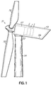
- Fig. 1 is a sideview of parts of a horizontal axis wind turbine comprising a rotor 51, with three blades 52, a nacelle 53 to which the rotor is rotatably mounted and which in turn is mounted on top of a tower 54.
- the nacelle comprises a nacelle structure including a bedframe 55 rotatably mounted on the tower for yawing, and a nacelle frame 56 connected to the bedframe 55.
- the rotor is mounted to a mainshaft (not shown) which is rotatably mounted to a mainshaft housing 57 which in turn is fixed to the bedframe 55.
- the wind turbine further comprises a drivetrain component 1 in the form of an assembly of a gearbox 2 and a generator 3 in the nacelle 53. It should be noted that for this presentation, the generator is considered as a drivetrain component.
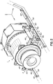
- Fig. 2 shows the component 1 disassembled from other drive components such as a main shaft (not shown), which is in the operational state of the wind turbine connecting the gearbox and a rotor of the wind turbine, which rotor comprises at least one blade.
- the stationary housing of the gearbox 2 is connected to the main shaft housing 57 by means of a flange 201 on the gearbox 2, a cooperating flange on the main shaft housing and bolts connecting the flanges.
- the main shaft housing 57 is mounted on the bedframe 55, the gearbox 2 and the generator 3 are in the mounted state cantilevered from the main shaft housing 57, and connected to the nacelle structure 55,56 via the main shaft housing 57.
- the gearbox 2 and the generator 3 can have respective direct connections to the nacelle structure 55, 56.
- a nacelle fixed coordinate system (see fig. 2 ) is defined as follows:
- the x-axis is parallel to the rotational axis of the wind turbine rotor, the y-axis is horizontal and perpendicular to the x-axis, and the z-axis that is perpendicular to the x-axis and to the y-axis.
- the rotor axis is inclined, e.g. 10 degrees, to a horizontal plane, and in such a turbine, the x-axis as defined above would of course also be inclined.
- a tool 4 for moving the drivetrain component 1 in the nacelle comprises two supporting units 401 mounted to a respective longitudinal member 561 of the nacelle structure.
- the support units 401 are elongated, oriented parallel to the x-axis, and distributed in along the y-axis so as to be located on either side of the component 1 in the mounted state thereof. Further in this embodiment the support units 401 are located at a lower portion of the component in the mounted state thereof, and have the shape of flanges 401 protruding from the respective longitudinal member 5 of the nacelle structure.
- the tool 4 further comprises two transport assemblies 402 each arranged so as to cooperate with a respective of the support units 401 and thus similarly located on either side of the component 1.
- Each transport assembly 402 comprises a carrier in turn comprising a vehicle, here embodied as a sled 403.
- Each carrier also comprises two first position adjustment devices 405, and two second position adjustment devices 406.
- Each transport assembly 402 also comprises an interface portion 404, for connection to the component, and a drive unit 407.
- each sled 403 has on its surface facing the support unit 401 pads 408 in a low friction material, to facilitate a sliding motion of the sled 403 on the support unit 401.
- the interface portion 404 has flanges for its connection to cooperating flanges 202 ( fig. 2 ) on the gearbox 2 by means of pins through holes in the flanges. The connection between the sled 403 and the component is described closer below.
- the drive units 407 are in the form of linear actuators. Here they are hydraulic linear actuators, but alternatively, they could be electric linear actuators or screw type actuators, e.g. provided with screws extending along the x-axis and engaging female threads in the sleds 403, which would move by twisting the screws.
- the linear actuators 407 are adapted to be connected to the nacelle structure and to the sled 403, so as to drive the sled 403 with the component in a direction parallel to the rotational axis of the rotor. More particularly, when the gearbox 2 released from the main shaft housing 57, the gearbox and generator assembly 1 can be moved along the x-axis by means on the sleds 403 and the linear actuators 407.
- each first position adjustment device 405 is a hydraulic linear actuator adapted to act between a first location 4051 on the sled 403 and a second location 4052 on the interface portion 404, the second location being higher than the first location.
- the position adjustment devices 405, 406 can alternatively be provided as some other type of actuators, e.g. electric linear actuators, or screw type linear actuators, (including screws engaging female threads so as to cause movement by twisting the screws).
- the interface portion 404 comprises a first intermediate device 4041 to which the first position adjustment devices 405 are connected at said second location 4052.
- the interface portion 404 also comprises a second intermediate device 4042.
- the first and second intermediate devices 4041, 4042 are separated from each other.
- Two second intermediate devices 4042 are mounted to cooperating flanges of the generator, on respective sides thereof.
- the assembly including the first intermediate device 4041, the first position adjustment devices 405, and the sled 403 is herein referred to as a carrier.
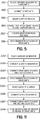
- the method includes placing S101 two carriers 403, 405, 4041 adjacent the generator 3, i.e. on a respective of the elongated support units 401, so as to be placed on respective sides of the generator. Thereby the first and second intermediate devices 4041, 4042 are placed next to each other. Thereafter the drive units 407 are connected S102 between the sled and the nacelle structure. In this embodiment, the direction of the drive units 407 is changed depending on the component that is being handled. When the generator only is to be moved, the drive units 407 are placed on a side of the carriers 403, 405, 4041 towards the rotor, but as can be seen in fig. 2 , when the gearbox 2 and the generator 3 are moved simultaneously, the drive units 407 are placed on a side of the carriers away from the rotor.
- the tool 4 could alternatively comprise only one supporting unit 401 mounted underneath the component 1, and only one transport assembly 402, Thereby the first position adjustment devices 405 can be distributed along the x-axis, so that the attitude of the component can be changed.
- the second position adjustment devices 406 are each adapted to provide a force between the component and the nacelle structure, which force is parallel to the plane defined by the x-axis and the y-axis.
- Each of the second position adjustment devices 406 comprises a hydraulic actuator 4061 and a lever arm 4062 rotatably mounted, at an articulated joint 4063, to the sled 403.
- the hydraulic actuator 4061 is adapted to push an upper end of the lever arm 4062 in the direction of the y-axis so a lower end of the lever arm 4062 below the joint 4063 contacts and pushes against the support unit 401, thereby urging the transport assembly 402 and the component 1 in the direction of the y-axis, i.e. laterally.
- the sleds 403 slide laterally on the support units 401.
- the first position adjustment devices 405 act between two other parts of the transport assembly 402, namely the sled 403 and the interface portion 404, and the second position adjustment devices 406 act between the transport assembly 402 and the support unit 401.
- Alternatives are of course possible for the arrangement of the position adjustment devices 405, 406. For example they could act between the transport arrangement 402 and the component 1, between the transport arrangement 402 and the nacelle structure 56, or even directly between the component 1 and the nacelle structure 56.
- each drive unit 407 is adapted to be connected to the nacelle structure at more than one location, so that the location of the connection between the nacelle structure and the drive units can be selected depending on the component to be handled.
- a variation of this solution has already been described above with reference to fig. 2 , fig. 5 and fig. 6 where the direction of the drive units 407 was changed.
- a sled 403 is placed S201 on each side of a first component, in this case the generator 3, between the generator 3 and the nacelle structure. Thereafter the sleds 403 are connected S202 to the generator 3, for example as described above with reference to fig. 5 and fig. 6 , and the drive units 407 are connected S203 between the sleds 403 and respective first locations L1 which are fixed in relation to the nacelle structure. Subsequently the sleds and the generator are moved S204 by means of the drive units 407.
- the sleds 403 are placed S205 on respective sides of the gearbox 2 ( fig. 10 ), between the gearbox 2 and the nacelle structure. Thereafter the sleds 403 are connected S206 to the gearbox 2, for example as described above with reference to fig. 5 and fig. 6 , and the drive units 407 are connected S207 between the sleds 403 and respective second locations L2 which are fixed in relation to the nacelle structure. Subsequently the sleds 403, the gearbox 2 and the generator 3 are moved S208 by means of the drive units 407.
Landscapes
- Engineering & Computer Science (AREA)
- Mechanical Engineering (AREA)
- Life Sciences & Earth Sciences (AREA)
- Sustainable Development (AREA)
- Sustainable Energy (AREA)
- Chemical & Material Sciences (AREA)
- Combustion & Propulsion (AREA)
- General Engineering & Computer Science (AREA)
- Wind Motors (AREA)
- Types And Forms Of Lifts (AREA)
Applications Claiming Priority (4)
| Application Number | Priority Date | Filing Date | Title |
|---|---|---|---|
| US42328710P | 2010-12-15 | 2010-12-15 | |
| DKPA201001126 | 2010-12-15 | ||
| EP11793649.2A EP2652320B1 (de) | 2010-12-15 | 2011-11-25 | Werkzeug und verfahren zum bewegen eines antriebsstrangelements einer windturbine |
| PCT/DK2011/050451 WO2012079575A1 (en) | 2010-12-15 | 2011-11-25 | A tool and a method for moving a wind turbine drivetrain component |
Related Parent Applications (2)
| Application Number | Title | Priority Date | Filing Date |
|---|---|---|---|
| EP11793649.2A Division EP2652320B1 (de) | 2010-12-15 | 2011-11-25 | Werkzeug und verfahren zum bewegen eines antriebsstrangelements einer windturbine |
| EP11793649.2A Division-Into EP2652320B1 (de) | 2010-12-15 | 2011-11-25 | Werkzeug und verfahren zum bewegen eines antriebsstrangelements einer windturbine |
Publications (2)
| Publication Number | Publication Date |
|---|---|
| EP3081807A1 true EP3081807A1 (de) | 2016-10-19 |
| EP3081807B1 EP3081807B1 (de) | 2019-09-18 |
Family
ID=46244128
Family Applications (3)
| Application Number | Title | Priority Date | Filing Date |
|---|---|---|---|
| EP16165517.0A Not-in-force EP3081807B1 (de) | 2010-12-15 | 2011-11-25 | Werkzeug und verfahren zum bewegen eines antriebsstrangelements einer windturbine |
| EP11793649.2A Not-in-force EP2652320B1 (de) | 2010-12-15 | 2011-11-25 | Werkzeug und verfahren zum bewegen eines antriebsstrangelements einer windturbine |
| EP11801966.0A Active EP2652317B1 (de) | 2010-12-15 | 2011-12-08 | Transport von Antriebsstrangkomponenten in einer Windturbinengondel |
Family Applications After (2)
| Application Number | Title | Priority Date | Filing Date |
|---|---|---|---|
| EP11793649.2A Not-in-force EP2652320B1 (de) | 2010-12-15 | 2011-11-25 | Werkzeug und verfahren zum bewegen eines antriebsstrangelements einer windturbine |
| EP11801966.0A Active EP2652317B1 (de) | 2010-12-15 | 2011-12-08 | Transport von Antriebsstrangkomponenten in einer Windturbinengondel |
Country Status (5)
| Country | Link |
|---|---|
| US (3) | US9709038B2 (de) |
| EP (3) | EP3081807B1 (de) |
| CN (2) | CN103299071B (de) |
| ES (2) | ES2593967T3 (de) |
| WO (2) | WO2012079575A1 (de) |
Families Citing this family (22)
| Publication number | Priority date | Publication date | Assignee | Title |
|---|---|---|---|---|
| EP3052802B1 (de) | 2013-10-04 | 2020-01-08 | Inventus Holdings, LLC | Ersatz einer uptower-windturbinenkomponente |
| JP6242779B2 (ja) * | 2013-10-09 | 2017-12-06 | 三菱重工業株式会社 | 風力発電装置の機器搬送方法及び風力発電装置 |
| DE102014216244A1 (de) * | 2014-08-15 | 2016-03-03 | Siemens Aktiengesellschaft | Verfahren zum Austausch eines Wälzlagers und Verfahren zum axialen Verschieben eines WKA-Getriebes |
| CN104964024B (zh) * | 2015-06-26 | 2017-04-12 | 广东明阳风电产业集团有限公司 | 一种风力发电机组主机运输用的传动系统固定装置 |
| SE539182C2 (en) * | 2015-07-02 | 2017-05-02 | Seatwirl Ab | Floating wind energy harvesting apparatus with replaceable energy converter |
| US11506179B2 (en) | 2016-11-11 | 2022-11-22 | Siemens Gamesa Renewable Energy A/S | Transport assembly |
| US10029719B2 (en) * | 2016-11-21 | 2018-07-24 | Inventus Holdings, Llc | Foldable utility cart |
| US10655609B2 (en) | 2017-02-23 | 2020-05-19 | General Electric Company | System and method for removal of a wind turbine gearbox from a main rotor shaft |
| WO2019042508A1 (en) * | 2017-08-29 | 2019-03-07 | Vestas Wind Systems A/S | TRANSPORT SYSTEM FOR MOVING TRANSMISSION COMPONENTS |
| ES2942154T3 (es) * | 2017-08-29 | 2023-05-30 | Vestas Wind Sys As | Una turbina eólica con un sistema de transporte para mover componentes de tren de transmisión |
| WO2019042507A1 (en) * | 2017-08-29 | 2019-03-07 | Vestas Wind Systems A/S | METHOD FOR MOUNTING OR DISASSEMBLING A WIND ELEMENT |
| US11536361B2 (en) | 2018-03-08 | 2022-12-27 | General Electric Company | Modular gearbox for wind turbine |
| US11231017B2 (en) * | 2019-03-29 | 2022-01-25 | General Electric Company | System and method for the service and exchange of a yaw bearing for a machine head of a wind turbine |
| JP7252857B2 (ja) * | 2019-08-01 | 2023-04-05 | 三菱重工業株式会社 | 浮体構造物設置システム、及び、浮体構造物設置方法 |
| CN112664392B (zh) | 2019-10-15 | 2025-09-05 | 通用电气可再生能源西班牙有限公司 | 用于在延长的维护期间锁定风力涡轮转子的系统和方法 |
| CN115053064B (zh) * | 2020-02-17 | 2025-08-08 | 维斯塔斯风力系统有限公司 | 用于风力涡轮机的机舱及制造风力涡轮机的方法 |
| EP4144986B1 (de) | 2021-09-06 | 2024-11-06 | General Electric Renovables España S.L. | Windturbinengondel mit mindestens einer verschiebbaren dachplatte |
| CN115076043B (zh) * | 2022-05-25 | 2025-12-05 | 国能联合动力技术(赤峰)有限公司 | 一种风机传动链可调转运装置及其工作方法 |
| CN117662406A (zh) * | 2022-08-30 | 2024-03-08 | 江苏金风科技有限公司 | 风力发电机组 |
| EP4488511A1 (de) * | 2023-07-01 | 2025-01-08 | General Electric Renovables España S.L. | Verfahren zur extraktion von transformatoren einer gondel einer windturbine |
| EP4502368A1 (de) * | 2023-08-02 | 2025-02-05 | Siemens Gamesa Renewable Energy A/S | Handhabungsvorrichtung |
| DE102023210658B4 (de) * | 2023-10-27 | 2026-02-19 | Zf Friedrichshafen Ag | Anordnung und Verfahren zur Montage und Demontage von zwei Bauteilen |
Citations (3)
| Publication number | Priority date | Publication date | Assignee | Title |
|---|---|---|---|---|
| WO2009074859A2 (de) * | 2007-12-11 | 2009-06-18 | Innovative Windpower Ag | Wartungsvorrichtung einer windenergieanlage |
| EP2147885A1 (de) * | 2008-07-24 | 2010-01-27 | General Electric Company | Tragbares Kransystem für Windradbauteile |
| US20100275442A1 (en) * | 2009-09-25 | 2010-11-04 | General Electric Company | Method and system for disengaging a shrink coupling on a turbine generator |
Family Cites Families (32)
| Publication number | Priority date | Publication date | Assignee | Title |
|---|---|---|---|---|
| US3665148A (en) * | 1971-04-07 | 1972-05-23 | Gen Motors Corp | Six-axis manipulator |
| SE428042B (sv) | 1981-09-07 | 1983-05-30 | Asea Ab | Vindkraftverk med maskinkabin |
| DE19916453A1 (de) | 1999-04-12 | 2000-10-19 | Flender A F & Co | Windkraftanlage |
| DK173530B2 (da) | 1999-11-17 | 2005-07-18 | Siemens Wind Power As | Fremgangsmåde til montering af hovedkomponenter i kabine på vindmölle og en sådan kabine til vindmölle |
| DE29924115U1 (de) * | 1999-11-18 | 2002-02-14 | Enron Wind GmbH, 48499 Salzbergen | Windkraftanlage |
| DE10117948A1 (de) * | 2001-04-10 | 2002-10-17 | Heller Geb Gmbh Maschf | Antrieb für Maschinenaggregate, wie Schlitten, Greifeinrichtungen u. dgl. |
| EP1291521A1 (de) | 2001-09-06 | 2003-03-12 | Turbowinds N.V./S.A. | Windkraftanlage mit bewegbarem Bordkran |
| EP1336755A1 (de) * | 2002-02-19 | 2003-08-20 | Vestas Wind Systems A/S | Verfahren zum Transport von einer Maschinengondel einer Windturbine |
| ES2316200B1 (es) * | 2004-12-21 | 2010-01-11 | GAMESA INNOVATION & TECHNOLOGY, S.L. | Aerogenerador con grua desmontable y pescante auxiliar y procedimiento de montaje de dicha grua. |
| EP1677032B1 (de) | 2004-12-31 | 2008-11-19 | Eickhoff Maschinenfabrik GmbH | Planeten-Austauschverfahren und Montagebolzen |
| CN101432216B (zh) * | 2005-12-30 | 2012-08-29 | 通用风能有限责任公司 | 用于将风力涡轮机组件起吊到塔顶部的设备 |
| US7704024B2 (en) * | 2006-01-31 | 2010-04-27 | General Electric Company | Methods and systems for transporting wind turbine components |
| AU2006338693B2 (en) | 2006-02-27 | 2011-04-28 | Alstom Wind S.L. | Method and system for hoisting heavy parts onto a wind turbine |
| CN101479471B (zh) * | 2006-06-29 | 2013-03-20 | 维斯塔斯风力系统有限公司 | 用于风轮机机舱的处理系统、用于垂直移置风轮机机舱的方法及风轮机机舱 |
| JP4885071B2 (ja) * | 2007-06-19 | 2012-02-29 | 三菱重工業株式会社 | 風車用設備の交換方法 |
| ES2444790T3 (es) * | 2008-06-27 | 2014-02-26 | Vestas Wind Systems A/S | Puente grúa para góndola |
| DE102008033066B4 (de) * | 2008-07-15 | 2014-03-27 | Repower Systems Se | Demontage eines Getriebes einer Windenergieanlage |
| KR101038641B1 (ko) | 2008-09-01 | 2011-06-03 | 두산중공업 주식회사 | 풍력터빈설비의 유지 보수 시스템 |
| US8075442B2 (en) | 2008-09-05 | 2011-12-13 | General Electric Company | System and assembly for power transmission and generation in a wind turbine |
| DE102008047769B4 (de) | 2008-09-17 | 2013-04-11 | Suzlon Energy Gmbh | Hubvorrichtung für eine Windturbine |
| SE534035C2 (sv) | 2009-04-08 | 2011-04-12 | Ncc Construction Sverige Ab | Förfarande för byggande av vindkraftverk |
| DK2363598T3 (en) * | 2010-02-26 | 2018-12-17 | Siemens Ag | Windmill |
| US7944079B1 (en) * | 2010-04-21 | 2011-05-17 | General Electric Company | Systems and methods for assembling a gearbox handling assembly for use in a wind turbine |
| US9022739B2 (en) * | 2011-02-07 | 2015-05-05 | Vestas Wind Systems A/S | Wind turbine generator with a lifting device |
| EP2505541B1 (de) * | 2011-03-31 | 2016-11-30 | ALSTOM Renewable Technologies | Windturbine |
| ITMI20111606A1 (it) * | 2011-09-07 | 2013-03-08 | Wilic Sarl | Unita' ausiliaria per aerogeneratore |
| US8500400B2 (en) * | 2011-09-20 | 2013-08-06 | General Electric Company | Component handling system for use in wind turbines and methods of positioning a drive train component |
| CN104066973B (zh) * | 2011-11-25 | 2017-04-26 | 维斯塔斯风力系统有限公司 | 用于使风轮机的传动系部件移动的工具及方法 |
| US20140286788A1 (en) * | 2011-11-29 | 2014-09-25 | Daewoo Shipbuilding & Marine Engineering Co., Ltd. | Wind power generator |
| US20130223964A1 (en) * | 2012-02-27 | 2013-08-29 | General Electric Company | Tower-based platform system for lifting components atop a wind turbine tower |
| US9238923B2 (en) * | 2012-12-21 | 2016-01-19 | Acciona Windpower, S.A. | Wind turbine assembly system |
| US9429138B2 (en) * | 2013-08-09 | 2016-08-30 | Gamesa Innovation & Technology, S.L. | Apparatus, system and method for wind turbine component replacement |
-
2011
- 2011-11-25 US US13/994,644 patent/US9709038B2/en not_active Expired - Fee Related
- 2011-11-25 CN CN201180064923.8A patent/CN103299071B/zh not_active Expired - Fee Related
- 2011-11-25 EP EP16165517.0A patent/EP3081807B1/de not_active Not-in-force
- 2011-11-25 ES ES11793649.2T patent/ES2593967T3/es active Active
- 2011-11-25 WO PCT/DK2011/050451 patent/WO2012079575A1/en not_active Ceased
- 2011-11-25 EP EP11793649.2A patent/EP2652320B1/de not_active Not-in-force
- 2011-12-08 EP EP11801966.0A patent/EP2652317B1/de active Active
- 2011-12-08 WO PCT/DK2011/050469 patent/WO2012079579A1/en not_active Ceased
- 2011-12-08 US US13/994,646 patent/US9228567B2/en active Active
- 2011-12-08 ES ES11801966.0T patent/ES2568903T3/es active Active
- 2011-12-08 CN CN201180067360.8A patent/CN103370533B/zh active Active
-
2017
- 2017-06-12 US US15/620,217 patent/US10302069B2/en active Active
Patent Citations (3)
| Publication number | Priority date | Publication date | Assignee | Title |
|---|---|---|---|---|
| WO2009074859A2 (de) * | 2007-12-11 | 2009-06-18 | Innovative Windpower Ag | Wartungsvorrichtung einer windenergieanlage |
| EP2147885A1 (de) * | 2008-07-24 | 2010-01-27 | General Electric Company | Tragbares Kransystem für Windradbauteile |
| US20100275442A1 (en) * | 2009-09-25 | 2010-11-04 | General Electric Company | Method and system for disengaging a shrink coupling on a turbine generator |
Also Published As
| Publication number | Publication date |
|---|---|
| US10302069B2 (en) | 2019-05-28 |
| EP2652317B1 (de) | 2016-03-23 |
| US20140186183A1 (en) | 2014-07-03 |
| CN103370533B (zh) | 2015-11-25 |
| CN103299071B (zh) | 2016-04-20 |
| WO2012079575A1 (en) | 2012-06-21 |
| CN103299071A (zh) | 2013-09-11 |
| EP2652320B1 (de) | 2016-08-24 |
| WO2012079579A1 (en) | 2012-06-21 |
| US9228567B2 (en) | 2016-01-05 |
| ES2593967T3 (es) | 2016-12-14 |
| ES2568903T3 (es) | 2016-05-05 |
| US9709038B2 (en) | 2017-07-18 |
| US20170276121A1 (en) | 2017-09-28 |
| CN103370533A (zh) | 2013-10-23 |
| EP2652320A1 (de) | 2013-10-23 |
| EP3081807B1 (de) | 2019-09-18 |
| EP2652317A1 (de) | 2013-10-23 |
| US20140017047A1 (en) | 2014-01-16 |
Similar Documents
| Publication | Publication Date | Title |
|---|---|---|
| US10302069B2 (en) | Tool and a method for moving a wind turbine drivetrain component | |
| US10508643B2 (en) | Tool and a method for moving a wind turbine drivetrain component | |
| KR101284629B1 (ko) | 배관 착탈용 지그 | |
| EP2068067A1 (de) | Dreibeinständer für Messgeräte mit Gelenkarm | |
| CN203843841U (zh) | 柔性机械助力臂 | |
| EP2971355B1 (de) | Schienensystem für arbeitsturm | |
| CN102079364B (zh) | 风机安装船及其重心调节装置 | |
| CN105270986A (zh) | 风力涡轮机叶片起吊设备及用于起吊风力涡轮机叶片的方法 | |
| CN104318828A (zh) | 一种用于空间多维展开机构的零重力实验系统 | |
| CN203141081U (zh) | 一种车轴与齿轮箱的组装平台 | |
| CN102806460A (zh) | 一种兆瓦级风力发电机组发电机对中调节装置 | |
| EP2495433A1 (de) | Windturbine, Hebewerkzeug und Verfahren zum Anheben eines Getriebedrehmomentarms | |
| CN206988755U (zh) | 一种用于机电工程的设备安装底座 | |
| CN109357857A (zh) | 车钩连挂试验系统 | |
| CN202994453U (zh) | 一种旋翼试验台操纵匹配机构 | |
| CN207246684U (zh) | 一种巡检机器人云台升降系统 | |
| CN104553611B (zh) | 减震系数可调的减震双向制动脚轮 | |
| CN205087808U (zh) | 提升机构及具有该提升机构的运输设备 | |
| CN102211750B (zh) | 自顶升工作平台装置 | |
| ES2719003T3 (es) | Herramienta y método para mover un componente de tren de accionamiento de turbina eólica | |
| CN203171247U (zh) | 电动升降悬臂装置 | |
| CN106134447B (zh) | 一种用于模拟真空环境短路试验的多余物释放装置 | |
| CN108405654A (zh) | 一种用于轻型起吊机轴轮镶嵌的推送压平装置 | |
| CN110077990A (zh) | 一种起落架机轮柔性拆卸装置 |
Legal Events
| Date | Code | Title | Description |
|---|---|---|---|
| PUAI | Public reference made under article 153(3) epc to a published international application that has entered the european phase |
Free format text: ORIGINAL CODE: 0009012 |
|
| AC | Divisional application: reference to earlier application |
Ref document number: 2652320 Country of ref document: EP Kind code of ref document: P |
|
| AK | Designated contracting states |
Kind code of ref document: A1 Designated state(s): AL AT BE BG CH CY CZ DE DK EE ES FI FR GB GR HR HU IE IS IT LI LT LU LV MC MK MT NL NO PL PT RO RS SE SI SK SM TR |
|
| STAA | Information on the status of an ep patent application or granted ep patent |
Free format text: STATUS: REQUEST FOR EXAMINATION WAS MADE |
|
| 17P | Request for examination filed |
Effective date: 20170309 |
|
| RBV | Designated contracting states (corrected) |
Designated state(s): AL AT BE BG CH CY CZ DE DK EE ES FI FR GB GR HR HU IE IS IT LI LT LU LV MC MK MT NL NO PL PT RO RS SE SI SK SM TR |
|
| REG | Reference to a national code |
Ref country code: DE Ref legal event code: R079 Ref document number: 602011062252 Country of ref document: DE Free format text: PREVIOUS MAIN CLASS: F03D0001000000 Ipc: F03D0015000000 |
|
| GRAP | Despatch of communication of intention to grant a patent |
Free format text: ORIGINAL CODE: EPIDOSNIGR1 |
|
| STAA | Information on the status of an ep patent application or granted ep patent |
Free format text: STATUS: GRANT OF PATENT IS INTENDED |
|
| RIC1 | Information provided on ipc code assigned before grant |
Ipc: F03D 13/10 20160101ALI20190321BHEP Ipc: F03D 80/50 20160101ALI20190321BHEP Ipc: F03D 13/40 20160101ALI20190321BHEP Ipc: F03D 15/00 20160101AFI20190321BHEP Ipc: F03D 80/00 20160101ALI20190321BHEP |
|
| INTG | Intention to grant announced |
Effective date: 20190423 |
|
| GRAS | Grant fee paid |
Free format text: ORIGINAL CODE: EPIDOSNIGR3 |
|
| GRAA | (expected) grant |
Free format text: ORIGINAL CODE: 0009210 |
|
| STAA | Information on the status of an ep patent application or granted ep patent |
Free format text: STATUS: THE PATENT HAS BEEN GRANTED |
|
| AC | Divisional application: reference to earlier application |
Ref document number: 2652320 Country of ref document: EP Kind code of ref document: P |
|
| AK | Designated contracting states |
Kind code of ref document: B1 Designated state(s): AL AT BE BG CH CY CZ DE DK EE ES FI FR GB GR HR HU IE IS IT LI LT LU LV MC MK MT NL NO PL PT RO RS SE SI SK SM TR |
|
| REG | Reference to a national code |
Ref country code: GB Ref legal event code: FG4D |
|
| REG | Reference to a national code |
Ref country code: CH Ref legal event code: EP |
|
| REG | Reference to a national code |
Ref country code: DE Ref legal event code: R096 Ref document number: 602011062252 Country of ref document: DE |
|
| REG | Reference to a national code |
Ref country code: AT Ref legal event code: REF Ref document number: 1181614 Country of ref document: AT Kind code of ref document: T Effective date: 20191015 |
|
| REG | Reference to a national code |
Ref country code: IE Ref legal event code: FG4D |
|
| REG | Reference to a national code |
Ref country code: NL Ref legal event code: MP Effective date: 20190918 |
|
| PG25 | Lapsed in a contracting state [announced via postgrant information from national office to epo] |
Ref country code: SE Free format text: LAPSE BECAUSE OF FAILURE TO SUBMIT A TRANSLATION OF THE DESCRIPTION OR TO PAY THE FEE WITHIN THE PRESCRIBED TIME-LIMIT Effective date: 20190918 Ref country code: BG Free format text: LAPSE BECAUSE OF FAILURE TO SUBMIT A TRANSLATION OF THE DESCRIPTION OR TO PAY THE FEE WITHIN THE PRESCRIBED TIME-LIMIT Effective date: 20191218 Ref country code: NO Free format text: LAPSE BECAUSE OF FAILURE TO SUBMIT A TRANSLATION OF THE DESCRIPTION OR TO PAY THE FEE WITHIN THE PRESCRIBED TIME-LIMIT Effective date: 20191218 Ref country code: LT Free format text: LAPSE BECAUSE OF FAILURE TO SUBMIT A TRANSLATION OF THE DESCRIPTION OR TO PAY THE FEE WITHIN THE PRESCRIBED TIME-LIMIT Effective date: 20190918 Ref country code: FI Free format text: LAPSE BECAUSE OF FAILURE TO SUBMIT A TRANSLATION OF THE DESCRIPTION OR TO PAY THE FEE WITHIN THE PRESCRIBED TIME-LIMIT Effective date: 20190918 Ref country code: HR Free format text: LAPSE BECAUSE OF FAILURE TO SUBMIT A TRANSLATION OF THE DESCRIPTION OR TO PAY THE FEE WITHIN THE PRESCRIBED TIME-LIMIT Effective date: 20190918 |
|
| REG | Reference to a national code |
Ref country code: LT Ref legal event code: MG4D |
|
| PG25 | Lapsed in a contracting state [announced via postgrant information from national office to epo] |
Ref country code: LV Free format text: LAPSE BECAUSE OF FAILURE TO SUBMIT A TRANSLATION OF THE DESCRIPTION OR TO PAY THE FEE WITHIN THE PRESCRIBED TIME-LIMIT Effective date: 20190918 Ref country code: AL Free format text: LAPSE BECAUSE OF FAILURE TO SUBMIT A TRANSLATION OF THE DESCRIPTION OR TO PAY THE FEE WITHIN THE PRESCRIBED TIME-LIMIT Effective date: 20190918 Ref country code: GR Free format text: LAPSE BECAUSE OF FAILURE TO SUBMIT A TRANSLATION OF THE DESCRIPTION OR TO PAY THE FEE WITHIN THE PRESCRIBED TIME-LIMIT Effective date: 20191219 Ref country code: RS Free format text: LAPSE BECAUSE OF FAILURE TO SUBMIT A TRANSLATION OF THE DESCRIPTION OR TO PAY THE FEE WITHIN THE PRESCRIBED TIME-LIMIT Effective date: 20190918 |
|
| REG | Reference to a national code |
Ref country code: ES Ref legal event code: FG2A Ref document number: 2750585 Country of ref document: ES Kind code of ref document: T3 Effective date: 20200326 |
|
| REG | Reference to a national code |
Ref country code: AT Ref legal event code: MK05 Ref document number: 1181614 Country of ref document: AT Kind code of ref document: T Effective date: 20190918 |
|
| PG25 | Lapsed in a contracting state [announced via postgrant information from national office to epo] |
Ref country code: AT Free format text: LAPSE BECAUSE OF FAILURE TO SUBMIT A TRANSLATION OF THE DESCRIPTION OR TO PAY THE FEE WITHIN THE PRESCRIBED TIME-LIMIT Effective date: 20190918 Ref country code: PT Free format text: LAPSE BECAUSE OF FAILURE TO SUBMIT A TRANSLATION OF THE DESCRIPTION OR TO PAY THE FEE WITHIN THE PRESCRIBED TIME-LIMIT Effective date: 20200120 Ref country code: IT Free format text: LAPSE BECAUSE OF FAILURE TO SUBMIT A TRANSLATION OF THE DESCRIPTION OR TO PAY THE FEE WITHIN THE PRESCRIBED TIME-LIMIT Effective date: 20190918 Ref country code: EE Free format text: LAPSE BECAUSE OF FAILURE TO SUBMIT A TRANSLATION OF THE DESCRIPTION OR TO PAY THE FEE WITHIN THE PRESCRIBED TIME-LIMIT Effective date: 20190918 Ref country code: PL Free format text: LAPSE BECAUSE OF FAILURE TO SUBMIT A TRANSLATION OF THE DESCRIPTION OR TO PAY THE FEE WITHIN THE PRESCRIBED TIME-LIMIT Effective date: 20190918 Ref country code: NL Free format text: LAPSE BECAUSE OF FAILURE TO SUBMIT A TRANSLATION OF THE DESCRIPTION OR TO PAY THE FEE WITHIN THE PRESCRIBED TIME-LIMIT Effective date: 20190918 Ref country code: RO Free format text: LAPSE BECAUSE OF FAILURE TO SUBMIT A TRANSLATION OF THE DESCRIPTION OR TO PAY THE FEE WITHIN THE PRESCRIBED TIME-LIMIT Effective date: 20190918 |
|
| PG25 | Lapsed in a contracting state [announced via postgrant information from national office to epo] |
Ref country code: CZ Free format text: LAPSE BECAUSE OF FAILURE TO SUBMIT A TRANSLATION OF THE DESCRIPTION OR TO PAY THE FEE WITHIN THE PRESCRIBED TIME-LIMIT Effective date: 20190918 Ref country code: SK Free format text: LAPSE BECAUSE OF FAILURE TO SUBMIT A TRANSLATION OF THE DESCRIPTION OR TO PAY THE FEE WITHIN THE PRESCRIBED TIME-LIMIT Effective date: 20190918 Ref country code: SM Free format text: LAPSE BECAUSE OF FAILURE TO SUBMIT A TRANSLATION OF THE DESCRIPTION OR TO PAY THE FEE WITHIN THE PRESCRIBED TIME-LIMIT Effective date: 20190918 Ref country code: IS Free format text: LAPSE BECAUSE OF FAILURE TO SUBMIT A TRANSLATION OF THE DESCRIPTION OR TO PAY THE FEE WITHIN THE PRESCRIBED TIME-LIMIT Effective date: 20200224 |
|
| REG | Reference to a national code |
Ref country code: DE Ref legal event code: R097 Ref document number: 602011062252 Country of ref document: DE |
|
| REG | Reference to a national code |
Ref country code: CH Ref legal event code: PL |
|
| PLBE | No opposition filed within time limit |
Free format text: ORIGINAL CODE: 0009261 |
|
| STAA | Information on the status of an ep patent application or granted ep patent |
Free format text: STATUS: NO OPPOSITION FILED WITHIN TIME LIMIT |
|
| PG2D | Information on lapse in contracting state deleted |
Ref country code: IS |
|
| PG25 | Lapsed in a contracting state [announced via postgrant information from national office to epo] |
Ref country code: LI Free format text: LAPSE BECAUSE OF NON-PAYMENT OF DUE FEES Effective date: 20191130 Ref country code: CH Free format text: LAPSE BECAUSE OF NON-PAYMENT OF DUE FEES Effective date: 20191130 Ref country code: DK Free format text: LAPSE BECAUSE OF FAILURE TO SUBMIT A TRANSLATION OF THE DESCRIPTION OR TO PAY THE FEE WITHIN THE PRESCRIBED TIME-LIMIT Effective date: 20190918 Ref country code: MC Free format text: LAPSE BECAUSE OF FAILURE TO SUBMIT A TRANSLATION OF THE DESCRIPTION OR TO PAY THE FEE WITHIN THE PRESCRIBED TIME-LIMIT Effective date: 20190918 Ref country code: LU Free format text: LAPSE BECAUSE OF NON-PAYMENT OF DUE FEES Effective date: 20191125 Ref country code: IS Free format text: LAPSE BECAUSE OF FAILURE TO SUBMIT A TRANSLATION OF THE DESCRIPTION OR TO PAY THE FEE WITHIN THE PRESCRIBED TIME-LIMIT Effective date: 20200119 |
|
| REG | Reference to a national code |
Ref country code: BE Ref legal event code: MM Effective date: 20191130 |
|
| 26N | No opposition filed |
Effective date: 20200619 |
|
| PG25 | Lapsed in a contracting state [announced via postgrant information from national office to epo] |
Ref country code: SI Free format text: LAPSE BECAUSE OF FAILURE TO SUBMIT A TRANSLATION OF THE DESCRIPTION OR TO PAY THE FEE WITHIN THE PRESCRIBED TIME-LIMIT Effective date: 20190918 |
|
| PG25 | Lapsed in a contracting state [announced via postgrant information from national office to epo] |
Ref country code: IE Free format text: LAPSE BECAUSE OF NON-PAYMENT OF DUE FEES Effective date: 20191125 |
|
| PG25 | Lapsed in a contracting state [announced via postgrant information from national office to epo] |
Ref country code: BE Free format text: LAPSE BECAUSE OF NON-PAYMENT OF DUE FEES Effective date: 20191130 |
|
| PG25 | Lapsed in a contracting state [announced via postgrant information from national office to epo] |
Ref country code: CY Free format text: LAPSE BECAUSE OF FAILURE TO SUBMIT A TRANSLATION OF THE DESCRIPTION OR TO PAY THE FEE WITHIN THE PRESCRIBED TIME-LIMIT Effective date: 20190918 |
|
| PG25 | Lapsed in a contracting state [announced via postgrant information from national office to epo] |
Ref country code: MT Free format text: LAPSE BECAUSE OF FAILURE TO SUBMIT A TRANSLATION OF THE DESCRIPTION OR TO PAY THE FEE WITHIN THE PRESCRIBED TIME-LIMIT Effective date: 20190918 Ref country code: HU Free format text: LAPSE BECAUSE OF FAILURE TO SUBMIT A TRANSLATION OF THE DESCRIPTION OR TO PAY THE FEE WITHIN THE PRESCRIBED TIME-LIMIT; INVALID AB INITIO Effective date: 20111125 |
|
| PG25 | Lapsed in a contracting state [announced via postgrant information from national office to epo] |
Ref country code: TR Free format text: LAPSE BECAUSE OF FAILURE TO SUBMIT A TRANSLATION OF THE DESCRIPTION OR TO PAY THE FEE WITHIN THE PRESCRIBED TIME-LIMIT Effective date: 20190918 |
|
| PG25 | Lapsed in a contracting state [announced via postgrant information from national office to epo] |
Ref country code: MK Free format text: LAPSE BECAUSE OF FAILURE TO SUBMIT A TRANSLATION OF THE DESCRIPTION OR TO PAY THE FEE WITHIN THE PRESCRIBED TIME-LIMIT Effective date: 20190918 |
|
| PGFP | Annual fee paid to national office [announced via postgrant information from national office to epo] |
Ref country code: GB Payment date: 20221122 Year of fee payment: 12 Ref country code: FR Payment date: 20221122 Year of fee payment: 12 Ref country code: ES Payment date: 20221213 Year of fee payment: 12 Ref country code: DE Payment date: 20221128 Year of fee payment: 12 |
|
| P01 | Opt-out of the competence of the unified patent court (upc) registered |
Effective date: 20230521 |
|
| REG | Reference to a national code |
Ref country code: DE Ref legal event code: R119 Ref document number: 602011062252 Country of ref document: DE |
|
| GBPC | Gb: european patent ceased through non-payment of renewal fee |
Effective date: 20231125 |
|
| PG25 | Lapsed in a contracting state [announced via postgrant information from national office to epo] |
Ref country code: DE Free format text: LAPSE BECAUSE OF NON-PAYMENT OF DUE FEES Effective date: 20240601 |
|
| PG25 | Lapsed in a contracting state [announced via postgrant information from national office to epo] |
Ref country code: GB Free format text: LAPSE BECAUSE OF NON-PAYMENT OF DUE FEES Effective date: 20231125 |
|
| PG25 | Lapsed in a contracting state [announced via postgrant information from national office to epo] |
Ref country code: FR Free format text: LAPSE BECAUSE OF NON-PAYMENT OF DUE FEES Effective date: 20231130 |
|
| PG25 | Lapsed in a contracting state [announced via postgrant information from national office to epo] |
Ref country code: GB Free format text: LAPSE BECAUSE OF NON-PAYMENT OF DUE FEES Effective date: 20231125 Ref country code: FR Free format text: LAPSE BECAUSE OF NON-PAYMENT OF DUE FEES Effective date: 20231130 Ref country code: DE Free format text: LAPSE BECAUSE OF NON-PAYMENT OF DUE FEES Effective date: 20240601 |
|
| REG | Reference to a national code |
Ref country code: ES Ref legal event code: FD2A Effective date: 20250108 |
|
| PG25 | Lapsed in a contracting state [announced via postgrant information from national office to epo] |
Ref country code: ES Free format text: LAPSE BECAUSE OF NON-PAYMENT OF DUE FEES Effective date: 20231126 |
|
| PG25 | Lapsed in a contracting state [announced via postgrant information from national office to epo] |
Ref country code: ES Free format text: LAPSE BECAUSE OF NON-PAYMENT OF DUE FEES Effective date: 20231126 |