EP3081817A1 - Maschine mit einem verdichter oder einer pumpe - Google Patents
Maschine mit einem verdichter oder einer pumpe Download PDFInfo
- Publication number
- EP3081817A1 EP3081817A1 EP15163421.9A EP15163421A EP3081817A1 EP 3081817 A1 EP3081817 A1 EP 3081817A1 EP 15163421 A EP15163421 A EP 15163421A EP 3081817 A1 EP3081817 A1 EP 3081817A1
- Authority
- EP
- European Patent Office
- Prior art keywords
- fluid
- shaft
- frame
- machine according
- housing
- Prior art date
- Legal status (The legal status is an assumption and is not a legal conclusion. Google has not performed a legal analysis and makes no representation as to the accuracy of the status listed.)
- Granted
Links
Images

Classifications
-
- F—MECHANICAL ENGINEERING; LIGHTING; HEATING; WEAPONS; BLASTING
- F04—POSITIVE - DISPLACEMENT MACHINES FOR LIQUIDS; PUMPS FOR LIQUIDS OR ELASTIC FLUIDS
- F04D—NON-POSITIVE-DISPLACEMENT PUMPS
- F04D29/00—Details, component parts, or accessories
- F04D29/04—Shafts or bearings, or assemblies thereof
- F04D29/046—Bearings
- F04D29/0467—Spherical bearings
-
- F—MECHANICAL ENGINEERING; LIGHTING; HEATING; WEAPONS; BLASTING
- F04—POSITIVE - DISPLACEMENT MACHINES FOR LIQUIDS; PUMPS FOR LIQUIDS OR ELASTIC FLUIDS
- F04D—NON-POSITIVE-DISPLACEMENT PUMPS
- F04D1/00—Radial-flow pumps, e.g. centrifugal pumps; Helico-centrifugal pumps
-
- F—MECHANICAL ENGINEERING; LIGHTING; HEATING; WEAPONS; BLASTING
- F04—POSITIVE - DISPLACEMENT MACHINES FOR LIQUIDS; PUMPS FOR LIQUIDS OR ELASTIC FLUIDS
- F04D—NON-POSITIVE-DISPLACEMENT PUMPS
- F04D17/00—Radial-flow pumps, e.g. centrifugal pumps; Helico-centrifugal pumps
- F04D17/08—Centrifugal pumps
- F04D17/10—Centrifugal pumps for compressing or evacuating
-
- F—MECHANICAL ENGINEERING; LIGHTING; HEATING; WEAPONS; BLASTING
- F04—POSITIVE - DISPLACEMENT MACHINES FOR LIQUIDS; PUMPS FOR LIQUIDS OR ELASTIC FLUIDS
- F04D—NON-POSITIVE-DISPLACEMENT PUMPS
- F04D25/00—Pumping installations or systems
-
- F—MECHANICAL ENGINEERING; LIGHTING; HEATING; WEAPONS; BLASTING
- F04—POSITIVE - DISPLACEMENT MACHINES FOR LIQUIDS; PUMPS FOR LIQUIDS OR ELASTIC FLUIDS
- F04D—NON-POSITIVE-DISPLACEMENT PUMPS
- F04D29/00—Details, component parts, or accessories
- F04D29/04—Shafts or bearings, or assemblies thereof
- F04D29/046—Bearings
-
- F—MECHANICAL ENGINEERING; LIGHTING; HEATING; WEAPONS; BLASTING
- F04—POSITIVE - DISPLACEMENT MACHINES FOR LIQUIDS; PUMPS FOR LIQUIDS OR ELASTIC FLUIDS
- F04D—NON-POSITIVE-DISPLACEMENT PUMPS
- F04D29/00—Details, component parts, or accessories
- F04D29/04—Shafts or bearings, or assemblies thereof
- F04D29/046—Bearings
- F04D29/049—Roller bearings
-
- F—MECHANICAL ENGINEERING; LIGHTING; HEATING; WEAPONS; BLASTING
- F04—POSITIVE - DISPLACEMENT MACHINES FOR LIQUIDS; PUMPS FOR LIQUIDS OR ELASTIC FLUIDS
- F04D—NON-POSITIVE-DISPLACEMENT PUMPS
- F04D29/00—Details, component parts, or accessories
- F04D29/05—Shafts or bearings, or assemblies thereof, specially adapted for elastic fluid pumps
- F04D29/051—Axial thrust balancing
-
- F—MECHANICAL ENGINEERING; LIGHTING; HEATING; WEAPONS; BLASTING
- F04—POSITIVE - DISPLACEMENT MACHINES FOR LIQUIDS; PUMPS FOR LIQUIDS OR ELASTIC FLUIDS
- F04D—NON-POSITIVE-DISPLACEMENT PUMPS
- F04D29/00—Details, component parts, or accessories
- F04D29/05—Shafts or bearings, or assemblies thereof, specially adapted for elastic fluid pumps
- F04D29/056—Bearings
-
- F—MECHANICAL ENGINEERING; LIGHTING; HEATING; WEAPONS; BLASTING
- F04—POSITIVE - DISPLACEMENT MACHINES FOR LIQUIDS; PUMPS FOR LIQUIDS OR ELASTIC FLUIDS
- F04D—NON-POSITIVE-DISPLACEMENT PUMPS
- F04D29/00—Details, component parts, or accessories
- F04D29/05—Shafts or bearings, or assemblies thereof, specially adapted for elastic fluid pumps
- F04D29/056—Bearings
- F04D29/059—Roller bearings
-
- F—MECHANICAL ENGINEERING; LIGHTING; HEATING; WEAPONS; BLASTING
- F04—POSITIVE - DISPLACEMENT MACHINES FOR LIQUIDS; PUMPS FOR LIQUIDS OR ELASTIC FLUIDS
- F04D—NON-POSITIVE-DISPLACEMENT PUMPS
- F04D29/00—Details, component parts, or accessories
- F04D29/40—Casings; Connections of working fluid
-
- F—MECHANICAL ENGINEERING; LIGHTING; HEATING; WEAPONS; BLASTING
- F04—POSITIVE - DISPLACEMENT MACHINES FOR LIQUIDS; PUMPS FOR LIQUIDS OR ELASTIC FLUIDS
- F04D—NON-POSITIVE-DISPLACEMENT PUMPS
- F04D13/00—Pumping installations or systems
-
- F—MECHANICAL ENGINEERING; LIGHTING; HEATING; WEAPONS; BLASTING
- F04—POSITIVE - DISPLACEMENT MACHINES FOR LIQUIDS; PUMPS FOR LIQUIDS OR ELASTIC FLUIDS
- F04D—NON-POSITIVE-DISPLACEMENT PUMPS
- F04D13/00—Pumping installations or systems
- F04D13/16—Pumping installations or systems with storage reservoirs
Definitions
- the present invention relates to a machine comprising a chassis enclosing at least one functional element and a control unit, and equipped with a fluid compressor, and more particularly a high-speed fluid compressor.
- the fluid compressors equipping such machines are generally called turbochargers or centrifugal compressors. They are equipped with a stator and a rotor forming a permanent magnet synchronous motor (brushless motor). Compressors of this type can reach very high speeds, for example from 100,000 to 500,000 revolutions / minute. The motor drives the turbine at high speed, the turbine compressing the fluid.
- the fluid can be air, water, a gas, a refrigerant or any other suitable fluid.
- These compressors are used in many industrial, medical, pharmaceutical, food, automotive applications, particularly for the supply of compressed air, or refrigeration, heating or air conditioning applications, for the supply of compressed fluid.
- compressors are generally used in very large installations, the compressor being far from the equipment requiring compressed fluid.
- the compressed fluid is supplied by means of a supply circuit provided in the network.
- this supply circuit is long, which entails risks of leakage of fluid along the circuit. Leaks in a compressed air circuit cause pressure losses, which generates very significant financial losses.
- the network is kept under pressure at all times in order to be able to respond rapidly to the need of the equipment.
- the continuous operation of the compressor represents a significant electrical energy consumption.
- the motor shaft is rotatably mounted on a frame by means of two axial bearings.
- These bearings may include ball bearings.
- ball bearings it is difficult to obtain rotational speeds with such bearings because of the difference in speed between the balls and the rings.
- the balls used are ceramic, the life of such bearings is limited to a hundred hours because of high rotational speeds.
- Other types of bearing may be used, such as aerodynamic bearings.
- this type of bearing has the disadvantage of moving transversely at the time of starting or during a change of speed, which creates friction at the level of the bearing elements.
- the compressors are usually lubricated with a lubricant.
- the disadvantage is that the lubricant may mix with the fluid, so that the compressed fluid is polluted by the lubricant.
- impurities present in the central network may mingle with the compressed fluid. This is particularly dangerous, for example in the case of medical applications, such as dental applications, for which the compressed air arriving in the mouth must be healthy.
- the invention particularly aims to overcome the various disadvantages of machines equipped with known high-speed compressors.
- an object of the invention is to provide a machine comprising equipment requiring compressed fluid and having an independent operation.
- Another object of the invention is to provide a machine comprising equipment requiring compressed fluid and which makes it possible to reduce the consumption of electrical energy and to limit leakage energy losses along the fluid circuit.
- the invention also aims to provide a machine comprising a high-speed fluid compressor that does not require a lubricating agent and does not cause any pollution of the compressed fluid.
- the present invention relates to a machine comprising a frame comprising at least one functional element and a control unit.
- the machine according to the invention is particularly compact, reduces the length of the compressed fluid supply circuit so as to limit losses, and operates autonomously.
- the first housing can be provided in the fluid supply channel.
- said first housing can be provided in a first support element arranged centrally with respect to the axis of the shaft in the fluid supply channel, and held at the walls of said channel fluid supply by means of branches between which the fluid can flow.
- the second housing can be provided in a second support element disposed in the frame centrally with respect to the axis of the shaft and opposite the first support element.
- the second support element can be slidably mounted in the frame and be connected to said frame by elastic means arranged to absorb the play variations between the rotor and the stator.
- the fluid compressor further comprises at least two aerodynamic bearings provided substantially on each side of the rotor shaft.
- a first aerodynamic bearing can be provided upstream of the turbine, said first aerodynamic bearing being carried by a third support element arranged centrally with respect to the axis of the shaft in the channel of fluid supply, and maintained at the walls of said fluid supply channel by means of branches between which the fluid can flow.
- a first aerodynamic bearing may be provided downstream of the turbine.
- a second aerodynamic bearing may be provided at the end of the rotor shaft, on the opposite side to the fluid supply channel.
- At least one of the first and second ends of the rotor shaft may comprise a third housing having the shape of a cap disposed centrally with respect to the axis of the shaft and arranged to receive said free mounted spherical element in said third housing.
- the spherical element may be integral with at least one of the first and second ends of the rotor shaft.
- the fluid supply circuit may comprise a compressed fluid reservoir and optionally a pressure multiplier provided between the fluid compressor and the compressed fluid reservoir.
- control unit may comprise activation means of the fluid compressor arranged to activate said fluid compressor only if necessary by the functional element.
- a high-speed fluid compressor 1 of the turbocharger or centrifugal compressor type.
- the term "fluid compressor” generically refers to both a compressor used to increase the pressure of a gas and a pump used to increase the pressure of a liquid, by a mechanical process.
- the fluid may be air, a gas, water vapor, water, a refrigerant or any other suitable fluid.
- the compressor comprises a frame 2 in which are mounted a stator and a rotor, shown schematically under the references 4 and 5, respectively.
- the stator 4 and the rotor 5 interact to form a permanent magnet synchronous motor (brushless motor).
- the rotor 5 comprises a shaft 6 rotatably mounted on the frame 2 about an axis A by means of a first bearing 7 and a second bearing 8, the first bearing 7 being arranged to support the first axial end 9 of the shaft 6 and the second bearing 8 being arranged to support the second axial end 10 of the shaft 6.
- the first and second bearings 7 and 8 will be described in detail below.
- the shaft 6 carries a turbine 12 disposed on the side of the first axial end 9. It is of course possible to provide several turbines.
- the compressor 1 also comprises a fluid supply channel 14 in the direction of the turbine 12, a body 15, as well as an outlet channel of compressed fluid 16, these elements being integral with the frame 2.
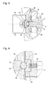
- the first bearing 7 comprises a first spherical element 18 disposed at the first end 9 of the shaft 6, centrally relative to the axis A of the shaft 6 and a first housing 20 provided on the frame 2 having the shape of a cap disposed centrally relative to the axis A of the shaft 6 and arranged to support said first spherical element 18.
- the second bearing 8 comprises a second spherical element 22 disposed at the second end 10 of the shaft 6, centrally with respect to the axis A of the shaft 6 and a second housing 24 provided on the frame 2 having the shape of a cap disposed centrally relative to the axis A of the shaft 6 and arranged to support said second spherical element 22.
- the first housing 20 supporting the first spherical element 18 is provided in the fluid supply channel 14.
- a first support element 26 having a truncated ovoid shape is disposed centrally with respect to the axis A of the shaft 6 in the fluid supply channel 14.
- the first housing 20 has the shape of a cap, solid surface, made at the end of the first support member 26 which is directed inwardly.
- the radius of the cap forming the first housing 20 is greater than the radius of the first spherical element 18.
- the dimensions of the first housing 20 and the first spherical element 18 are such that said first spherical element 18 is in contact with the curved bottom of the first housing 20
- the cap forming the first housing 20 and the first spherical element 18 are perfectly spherical in order to have a tangential contact between said first housing 20 and said first spherical element 18.
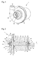
- the first support element 26 is maintained at internal walls of said fluid supply channel 14 by means of three branches 28 (cf. Figure 1 ). These branches 28 are spaced apart from each other so as to allow the fluid to enter the compressor.
- the first axial end 9 of the shaft 6 comprises a third housing 29 having the shape of a cap, with a solid surface, arranged centrally with respect to the axis A of the shaft 6 and arranged to receive the first spherical element 18 mounted free in said third housing 29.
- the radius of the cap forming the third housing 29 is greater than the radius of the first spherical element 18.
- the dimensions of the third housing 29 and the first spherical element 18 are such that said first spherical element 18 is in contact with the curved bottom of the third housing 29.
- the first spherical element 18 is in the form of a ball mounted freely between the two caps forming the first and third housings 20, 29 between which the first spherical element 18 is maintained.
- the cap forming the third housing 29 and the first spherical element 18 are perfectly spherical so as to have a tangential contact between said third housing 29 and said first spherical element 18.
- the radius of the cap forming the third housing 29 can be equal to or different from the radius of the cap forming the first housing 20.
- the second housing 24 supporting the second spherical element 22 is provided in a second support element 30 disposed in the frame 2 centrally with respect to the axis A of the shaft 6, and opposite the first element- 26.
- the second housing 24 is formed in the second support element 30 in the form of a cap, with a solid surface, disposed facing the shaft 6.
- the radius of the cap forming the second housing 24 is greater than the radius of the second spherical element 22.
- the dimensions of the second housing 24 and the second spherical element 22 are such that said second spherical element 22 is in contact with the curved bottom of the second housing 24.
- the cap forming the second housing 24 and the second spherical element 22 are perfectly spherical so as to have tangential contact between said second housing 24 and said second spherical element 22.
- the second support element 30 is mounted so that slidably in the frame 2 to which it is connected by elastic means 32, such as a spring, for absorbing the play variations between the rotor 5 and the stator 4.
- the second axial end 10 of the shaft 6 comprises a fourth housing 34 having the shape of a cap, with a solid surface, arranged centrally with respect to the axis A of the shaft 6 and arranged to receive the second spherical element 22 mounted free in said fourth housing 34.
- the radius of the cap forming the fourth housing 34 is greater than the radius of the second spherical element 22.
- the dimensions of the fourth housing 34 and the second spherical element 22 are such that said second spherical element 22 is in contact with the curved bottom of the fourth housing 34.
- the second spherical element 22 is in the form of a ball mounted freely between the two caps forming the second and fourth housings 24, 34 between which the second spherical element 22 is maintained.
- the cap forming the fourth housing 34 and the second spherical element 22 are perfectly spherical so as to have tangential contact between said fourth housing 34 and said second spherical element 22.
- the radius of the cap forming the fourth housing 34 can be equal to or different from the radius of the cap forming the second housing 24.
- the first spherical element 18 is integral with the first axial end 9 of the shaft 6.
- the second spherical element 22 may be integral with the second axial end 10 of the 6.
- the spherical element 18, 22 can be glued, driven on the end of the shaft 6, or formed in one piece with said shaft 6.
- the spherical element is preferably made of ceramic, or any other suitable material, said material may have a slippery surface treatment (for example a polytetrafluoroethylene coating, such as Teflon®, or any other suitable coating known from those skilled in the art to have an extremely low coefficient of friction).
- a slippery surface treatment for example a polytetrafluoroethylene coating, such as Teflon®, or any other suitable coating known from those skilled in the art to have an extremely low coefficient of friction.
- the fluid compressor 1 further comprises first and second aerodynamic bearings provided substantially on each side of the shaft 6 of the rotor, towards the first and second axial ends 9 and 10, and shown schematically under the references 36 and 38.
- the first aerodynamic bearing 36 is provided upstream of the turbine 12.
- a third support member 40 having a central body 42 arranged centrally with respect to the axis A of the shaft 6 in the fluid supply channel 14, downstream of the first support member 26.
- the first aerodynamic bearing 36 is housed in the central body 42.
- the third support member 40 is held at the inner walls of said fluid supply channel 14 by means of three branches 44. These branches 44 are spaced apart from each other so as to allow the fluid to enter the compressor. These branches 44 comprise channels for supplying air to the first aerodynamic bearing 36.
- the first aerodynamic bearing can be provided downstream of the turbine 12.
- the channels for supplying air to the first aerodynamic bearing 36 can then be provided in the frame 2, which simplifies the construction of the whole.
- the second aerodynamic bearing 38 is provided near the second axial end 10, and can be arranged to maintain axial and radial. According to a variant not shown, it is possible to associate the second support member 30 with an electromagnet system which allows, at low speed or in the event of a change of speed, to position said second support element 30 to support the second spherical element 22 to ensure the central positioning of the shaft 6 to ensure the axial and radial functional play at the second aerodynamic bearing 38. In other cases, the electromagnet system is arranged to move the second support element 30 of the second spherical element 22, and release said second spherical element 22, the aerodynamic bearing 38 then being sufficient to ensure the axial and radial functional play.
- aerodynamic bearings used are known to those skilled in the art and do not require detailed description here. It is obvious that the use of aerodynamic bearings is optional, only the first and second bearings 7 and 8 can be used.
- the machine 50 comprises a frame 52 enclosing at least one functional element 53 making it possible to perform the function of the machine, and a control unit 54.
- the machine comprises a fluid compressor 1 , as described above, said fluid compressor 1 being integrated in the machine, inside the frame 52.
- the frame 52 comprises a fluid inlet arranged to feed the fluid compressor 1 and bring the Fluid 52 also encloses a supply circuit 56 arranged to bring the compressed fluid leaving the fluid compressor 1 to the functional element 53.
- the frame 52 also encloses a compressed fluid reservoir 58 and a pressure multiplier 59 provided between the fluid compressor 1 and the compressed fluid reservoir 58.
- the frame 52 also contains a control unit 60 of the fluid compressor 1 arranged to activate the fluid compressor 1.
- the control unit 54 is arranged to communicate with the control unit 60 in order to activate the fluid compressor 1 only, if necessary, by the functional element 53.
- the fluid compressor 1 is disposed in the machine 50 by positioning the axis A of the shaft 6 of the rotor 5 vertically.
- This vertical position as well as the bearings used according to the invention comprising a single centered spherical element make it possible to keep the weight of the rotor 5 in the center and to minimize the risk of displacement of the shaft 6. This is then self centering. 6, the bearings used according to the invention for axial and radial retention.
- the use of aerodynamic bearings in combination with the bearings used according to the invention makes it possible to maintain a radial and axial functional clearance when starting or changing the speed of the rotor 5.
- the fluid compressor used according to the invention achieves very high speeds of rotation, between 100,000 rpm and 1,000,000 rpm. These very high speeds make it possible to provide a fluid compressor of smaller dimensions for the same power, allowing its integration into the chassis of a machine. Any connection of the machine to a compressor belonging to a central network is deleted. Thus, the circuit for supplying the compressed fluid to the functional element is very short. This reduces on the one hand the risk of leakage, and on the other hand avoids the pollution that may occur during the transport of compressed fluid through a central network. This also allows a very fast reaction time of the compressor, so that the latter can operate only at the request of the functional element.
- the fluid compressor 1 When no compressed fluid is requested by the functional element 53, the fluid compressor 1 is at a standstill so that there is no energy consumption during this rest period, hence a reduction in the overall energy consumption of the machine.
- the fluid compressor used according to the invention operates without agent of lubrication, so that no lubricant will pollute the compressed fluid.
- the machine according to the invention can be used in many applications, such as industrial applications, medical, pharmaceutical, food, automotive, including for the supply of compressed air, or refrigeration applications, heating or air conditioning, for the supply of compressed fluid.
Landscapes
- Engineering & Computer Science (AREA)
- Mechanical Engineering (AREA)
- General Engineering & Computer Science (AREA)
- Structures Of Non-Positive Displacement Pumps (AREA)
- Compressor (AREA)
Priority Applications (12)
| Application Number | Priority Date | Filing Date | Title |
|---|---|---|---|
| PT151634219T PT3081817T (pt) | 2015-04-13 | 2015-04-13 | Máquina equipada com um compressor |
| HUE15163421A HUE053996T2 (hu) | 2015-04-13 | 2015-04-13 | Kompresszort tartalmazó gép |
| ES15163421T ES2856014T3 (es) | 2015-04-13 | 2015-04-13 | Máquina equipada de un compresor |
| PL15163421T PL3081817T3 (pl) | 2015-04-13 | 2015-04-13 | Maszyna wyposażona w sprężarkę |
| SI201531570T SI3081817T1 (sl) | 2015-04-13 | 2015-04-13 | Stroj, ki vsebuje kompresor |
| EP15163421.9A EP3081817B1 (de) | 2015-04-13 | 2015-04-13 | Maschine mit einem verdichter |
| RS20210408A RS61689B1 (sr) | 2015-04-13 | 2015-04-13 | Mašina sa kompresorom |
| PCT/EP2016/055828 WO2016165906A1 (fr) | 2015-04-13 | 2016-03-17 | Machine equipée d'un compresseur d'air ou pompe à eau |
| US15/565,791 US10927844B2 (en) | 2015-04-13 | 2016-03-17 | Machine equipped with an air compressor or water pump |
| CN201680021406.5A CN107454927B (zh) | 2015-04-13 | 2016-03-17 | 配备有空气压缩机或水泵的机器 |
| JP2017553973A JP6694895B2 (ja) | 2015-04-13 | 2016-03-17 | エアコンプレッサーないし液体ポンプを備える機械 |
| HRP20210546TT HRP20210546T1 (hr) | 2015-04-13 | 2021-04-06 | Stroj koji ima kompresor |
Applications Claiming Priority (1)
| Application Number | Priority Date | Filing Date | Title |
|---|---|---|---|
| EP15163421.9A EP3081817B1 (de) | 2015-04-13 | 2015-04-13 | Maschine mit einem verdichter |
Publications (2)
| Publication Number | Publication Date |
|---|---|
| EP3081817A1 true EP3081817A1 (de) | 2016-10-19 |
| EP3081817B1 EP3081817B1 (de) | 2021-01-13 |
Family
ID=52991494
Family Applications (1)
| Application Number | Title | Priority Date | Filing Date |
|---|---|---|---|
| EP15163421.9A Active EP3081817B1 (de) | 2015-04-13 | 2015-04-13 | Maschine mit einem verdichter |
Country Status (12)
| Country | Link |
|---|---|
| US (1) | US10927844B2 (de) |
| EP (1) | EP3081817B1 (de) |
| JP (1) | JP6694895B2 (de) |
| CN (1) | CN107454927B (de) |
| ES (1) | ES2856014T3 (de) |
| HR (1) | HRP20210546T1 (de) |
| HU (1) | HUE053996T2 (de) |
| PL (1) | PL3081817T3 (de) |
| PT (1) | PT3081817T (de) |
| RS (1) | RS61689B1 (de) |
| SI (1) | SI3081817T1 (de) |
| WO (1) | WO2016165906A1 (de) |
Families Citing this family (6)
| Publication number | Priority date | Publication date | Assignee | Title |
|---|---|---|---|---|
| CN111989496B (zh) * | 2018-07-20 | 2021-12-31 | 株式会社Ihi | 电动压缩机 |
| USD902961S1 (en) * | 2019-03-01 | 2020-11-24 | Savant Holdings LLC | Compressor housing |
| US10927702B1 (en) | 2019-03-30 | 2021-02-23 | Savant Holdings LLC | Turbocharger or turbocharger component |
| USD900163S1 (en) * | 2020-02-20 | 2020-10-27 | Savant Holdings LLC | Compressor housing |
| DE102020121332B4 (de) * | 2020-08-13 | 2024-10-24 | Nidec Gpm Gmbh | Axialgleitlageranordnung für eine zu lagernde Welle eines Pumpenrads einer Radialpumpe sowie Radialpumpe aufweisend die Axialgleitlageranordnung |
| WO2022172652A1 (ja) * | 2021-02-09 | 2022-08-18 | 株式会社Ihi | 電動圧縮機 |
Citations (7)
| Publication number | Priority date | Publication date | Assignee | Title |
|---|---|---|---|---|
| EP0318638A2 (de) * | 1987-12-03 | 1989-06-07 | Rockwell International Corporation | Einschlussaufbau |
| EP1469189A1 (de) * | 2003-04-14 | 2004-10-20 | Caterpillar Inc. | Kraftstoffsystem für eine Brennkraftmaschine |
| KR20090126661A (ko) * | 2008-06-05 | 2009-12-09 | 한국기계연구원 | 윤활성 향상을 위한 스러스트 베어링이 설치된 인라인형엘피지 연료펌프 |
| JP2010168904A (ja) * | 2009-01-20 | 2010-08-05 | Jtekt Corp | 燃料電池用空気供給装置 |
| US20110038719A1 (en) * | 2009-08-11 | 2011-02-17 | Gm Global Technology Operations, Inc. | Simplified housing for a fuel cell compressor |
| EP2562298A2 (de) * | 2011-08-26 | 2013-02-27 | Maschinenfabrik Rieter Ag | Spurlager für einen Spinnrotor |
| CN103727043A (zh) * | 2014-01-03 | 2014-04-16 | 顾发华 | 双级离心压缩机和对所述双级离心压缩机的静压气浮轴承供气的方法 |
Family Cites Families (22)
| Publication number | Priority date | Publication date | Assignee | Title |
|---|---|---|---|---|
| FR703325A (fr) * | 1930-10-04 | 1931-04-28 | Perfectionnements aux pompes immergées | |
| US3951573A (en) * | 1946-07-16 | 1976-04-20 | The United States Of America As Represented By The United States Energy Research And Development Administration | Fluid lubricated bearing construction |
| US2839005A (en) * | 1953-10-14 | 1958-06-17 | Herbert E Means | Turbine driven pump |
| US3269117A (en) * | 1965-06-28 | 1966-08-30 | John H Tweet | Air driven turbopump |
| US4865529A (en) * | 1987-12-03 | 1989-09-12 | Rockwell International Corporation | Rotor transient positioning assembly |
| JPH0211918A (ja) * | 1988-06-29 | 1990-01-17 | Matsushita Electric Ind Co Ltd | 動圧型エア軸受装置 |
| JPH04137295U (ja) * | 1991-06-14 | 1992-12-21 | 株式会社イワキ | マグネツトポンプ |
| DE69517071T2 (de) * | 1994-02-23 | 2001-02-01 | Ebara Corp., Tokio/Tokyo | Pumpeneinheit mit Entspannungsturbine |
| JPH10184302A (ja) * | 1996-11-11 | 1998-07-14 | Daikin Ind Ltd | 流体機械 |
| JPH1175340A (ja) * | 1997-06-17 | 1999-03-16 | Nippon Densan Corp | モータ |
| JP2000297787A (ja) * | 1999-04-13 | 2000-10-24 | Matsushita Electric Ind Co Ltd | ポンプ |
| DE102008050314A1 (de) * | 2008-08-18 | 2010-02-25 | Daimler Ag | Verdichter und Verfahren zum Betreiben eines Verdichters sowie Brennstoffzelleneinrichtung mit einem Verdichter |
| CN201377516Y (zh) * | 2009-01-05 | 2010-01-06 | 圣格兰(嘉兴)光机电技术有限公司 | 一种三点接触式球轴承 |
| CN101782112A (zh) * | 2009-01-16 | 2010-07-21 | 上海天创纯滚动轴承有限公司 | 纯滚动轴承 |
| DE102010005409A1 (de) * | 2010-01-22 | 2011-07-28 | Minebea Co., Ltd. | Elektrische Maschine |
| CN201953830U (zh) * | 2010-12-30 | 2011-08-31 | 襄阳汽车轴承股份有限公司 | 椭圆沟道接触式离合器分离轴承 |
| JP5535992B2 (ja) * | 2011-07-15 | 2014-07-02 | 三菱重工業株式会社 | 電動過給圧縮機、その組立方法及び内燃機関 |
| DE102012013048A1 (de) * | 2012-06-29 | 2013-01-17 | Daimler Ag | Strömungsmaschine für einen Energiewandler sowie Brennstoffzelleneinrichtung mit einer solchen Strömungsmaschine |
| JP2014059030A (ja) * | 2012-09-19 | 2014-04-03 | Jtekt Corp | 転がり軸受 |
| CN203404098U (zh) * | 2013-07-05 | 2014-01-22 | 江苏丽天石化码头有限公司 | 逆循环型屏蔽泵的连接结构 |
| KR102130283B1 (ko) * | 2018-07-27 | 2020-08-05 | 주식회사 코아비스 | 임펠러 지지구조를 포함하는 워터 펌프 |
| KR102125868B1 (ko) * | 2018-10-15 | 2020-06-23 | 주식회사 코아비스 | 전동식 워터펌프용 임펠러 |
-
2015
- 2015-04-13 ES ES15163421T patent/ES2856014T3/es active Active
- 2015-04-13 EP EP15163421.9A patent/EP3081817B1/de active Active
- 2015-04-13 HU HUE15163421A patent/HUE053996T2/hu unknown
- 2015-04-13 SI SI201531570T patent/SI3081817T1/sl unknown
- 2015-04-13 PT PT151634219T patent/PT3081817T/pt unknown
- 2015-04-13 RS RS20210408A patent/RS61689B1/sr unknown
- 2015-04-13 PL PL15163421T patent/PL3081817T3/pl unknown
-
2016
- 2016-03-17 CN CN201680021406.5A patent/CN107454927B/zh active Active
- 2016-03-17 WO PCT/EP2016/055828 patent/WO2016165906A1/fr not_active Ceased
- 2016-03-17 US US15/565,791 patent/US10927844B2/en active Active
- 2016-03-17 JP JP2017553973A patent/JP6694895B2/ja active Active
-
2021
- 2021-04-06 HR HRP20210546TT patent/HRP20210546T1/hr unknown
Patent Citations (7)
| Publication number | Priority date | Publication date | Assignee | Title |
|---|---|---|---|---|
| EP0318638A2 (de) * | 1987-12-03 | 1989-06-07 | Rockwell International Corporation | Einschlussaufbau |
| EP1469189A1 (de) * | 2003-04-14 | 2004-10-20 | Caterpillar Inc. | Kraftstoffsystem für eine Brennkraftmaschine |
| KR20090126661A (ko) * | 2008-06-05 | 2009-12-09 | 한국기계연구원 | 윤활성 향상을 위한 스러스트 베어링이 설치된 인라인형엘피지 연료펌프 |
| JP2010168904A (ja) * | 2009-01-20 | 2010-08-05 | Jtekt Corp | 燃料電池用空気供給装置 |
| US20110038719A1 (en) * | 2009-08-11 | 2011-02-17 | Gm Global Technology Operations, Inc. | Simplified housing for a fuel cell compressor |
| EP2562298A2 (de) * | 2011-08-26 | 2013-02-27 | Maschinenfabrik Rieter Ag | Spurlager für einen Spinnrotor |
| CN103727043A (zh) * | 2014-01-03 | 2014-04-16 | 顾发华 | 双级离心压缩机和对所述双级离心压缩机的静压气浮轴承供气的方法 |
Also Published As
| Publication number | Publication date |
|---|---|
| CN107454927B (zh) | 2021-04-06 |
| CN107454927A (zh) | 2017-12-08 |
| PT3081817T (pt) | 2022-06-27 |
| WO2016165906A1 (fr) | 2016-10-20 |
| JP6694895B2 (ja) | 2020-05-20 |
| HUE053996T2 (hu) | 2021-08-30 |
| HRP20210546T1 (hr) | 2021-05-28 |
| RS61689B1 (sr) | 2021-05-31 |
| US10927844B2 (en) | 2021-02-23 |
| EP3081817B1 (de) | 2021-01-13 |
| SI3081817T1 (sl) | 2021-08-31 |
| JP2018514687A (ja) | 2018-06-07 |
| US20180119703A1 (en) | 2018-05-03 |
| PL3081817T3 (pl) | 2021-07-12 |
| ES2856014T3 (es) | 2021-09-27 |
Similar Documents
| Publication | Publication Date | Title |
|---|---|---|
| EP3081817B1 (de) | Maschine mit einem verdichter | |
| CA2938385C (fr) | Turbomachine equipee d'un groupe de lubrification | |
| EP2136073B1 (de) | Lagerung für einen Turbomaschinensatz | |
| FR3066558B1 (fr) | Module de soufflante a pales a calage variable | |
| FR3066559B1 (fr) | Module de soufflante a pales a calage variable | |
| EP3247924B1 (de) | Integration einer pumpe auf einem ritzelschaft | |
| EP2402613B1 (de) | Trockenvakuumpumpe | |
| FR2965858A1 (fr) | Amortisseur a compression de film liquide | |
| CA2874707A1 (fr) | Palier a moyen de lubrification et systeme pour changer le pas des pales d'une helice de turbopropulseur d'aeronef, equipe dudit palier | |
| FR2914384A1 (fr) | Double joint a levre pressurise. | |
| EP3081816B1 (de) | Verdichter mit zwei kugeln zum abstützen der welle | |
| EP3262283B1 (de) | Hydrodynamisches lager | |
| FR3065269A1 (fr) | Train d'engrenages epicycloidal | |
| FR3120661A1 (fr) | Compresseur à spirales ayant une pompe à huile centrifuge | |
| EP4127417B1 (de) | Fluggasturbinenaufbau welcher ein verbessertes schmiersystem eines ein gebläse antreibendes untersetzungsgetriebes umfasst | |
| WO2024115866A1 (fr) | Dispositif à arbre rotatif avec refroidissement et lubrification intégrés. | |
| EP4293203B1 (de) | Schmiermodul einer schmierstation einer strömungsmaschine | |
| FR3001014A1 (fr) | Bague exterieure fixe de roulement avec au moins un orifice de drainage traversant un rebord de guidage d'au moins un element roulant | |
| FR3098258A1 (fr) | Pompe à engrenages basculante pour turbomachine, incorporable à un circuit de lubrification de moteur d’aéronef | |
| FR3153635A1 (fr) | Dispositif pour le centrage et le guidage en rotation d’un arbre de turbomachine à lubrification optimisée d’éléments de roulement par du lubrifiant évacué depuis un palier à amortissement par compression de film d’huile | |
| EP4493799A1 (de) | Schmierung und kühlung von ausrüstung einer flugzeugturbomaschine | |
| FR2906567A1 (fr) | Turbocompresseur comprenant un rouet double pourvu d'un palier a air | |
| BE870198A (fr) | Elements en volute complementaires, notamment pour pompes a liquides | |
| EP4296474A1 (de) | Öltank für eine turbomaschine mit einem negativ kompatiblen zentrifugalrad | |
| FR3167667A1 (fr) | Turbomachine equipee d’une machine electrique et de moyens d’accouplement entre un arbre de la turbomachine et un arbre relie a la machine electrique |
Legal Events
| Date | Code | Title | Description |
|---|---|---|---|
| PUAI | Public reference made under article 153(3) epc to a published international application that has entered the european phase |
Free format text: ORIGINAL CODE: 0009012 |
|
| AK | Designated contracting states |
Kind code of ref document: A1 Designated state(s): AL AT BE BG CH CY CZ DE DK EE ES FI FR GB GR HR HU IE IS IT LI LT LU LV MC MK MT NL NO PL PT RO RS SE SI SK SM TR |
|
| AX | Request for extension of the european patent |
Extension state: BA ME |
|
| STAA | Information on the status of an ep patent application or granted ep patent |
Free format text: STATUS: REQUEST FOR EXAMINATION WAS MADE |
|
| 17P | Request for examination filed |
Effective date: 20170419 |
|
| RBV | Designated contracting states (corrected) |
Designated state(s): AL AT BE BG CH CY CZ DE DK EE ES FI FR GB GR HR HU IE IS IT LI LT LU LV MC MK MT NL NO PL PT RO RS SE SI SK SM TR |
|
| STAA | Information on the status of an ep patent application or granted ep patent |
Free format text: STATUS: EXAMINATION IS IN PROGRESS |
|
| 17Q | First examination report despatched |
Effective date: 20180323 |
|
| GRAP | Despatch of communication of intention to grant a patent |
Free format text: ORIGINAL CODE: EPIDOSNIGR1 |
|
| STAA | Information on the status of an ep patent application or granted ep patent |
Free format text: STATUS: GRANT OF PATENT IS INTENDED |
|
| INTG | Intention to grant announced |
Effective date: 20200810 |
|
| GRAS | Grant fee paid |
Free format text: ORIGINAL CODE: EPIDOSNIGR3 |
|
| GRAA | (expected) grant |
Free format text: ORIGINAL CODE: 0009210 |
|
| STAA | Information on the status of an ep patent application or granted ep patent |
Free format text: STATUS: THE PATENT HAS BEEN GRANTED |
|
| AK | Designated contracting states |
Kind code of ref document: B1 Designated state(s): AL AT BE BG CH CY CZ DE DK EE ES FI FR GB GR HR HU IE IS IT LI LT LU LV MC MK MT NL NO PL PT RO RS SE SI SK SM TR |
|
| REG | Reference to a national code |
Ref country code: GB Ref legal event code: FG4D Free format text: NOT ENGLISH |
|
| REG | Reference to a national code |
Ref country code: CH Ref legal event code: EP |
|
| REG | Reference to a national code |
Ref country code: DE Ref legal event code: R096 Ref document number: 602015064667 Country of ref document: DE |
|
| REG | Reference to a national code |
Ref country code: CH Ref legal event code: NV Representative=s name: ICB INGENIEURS CONSEILS EN BREVETS SA, CH |
|
| REG | Reference to a national code |
Ref country code: IE Ref legal event code: FG4D Free format text: LANGUAGE OF EP DOCUMENT: FRENCH |
|
| REG | Reference to a national code |
Ref country code: AT Ref legal event code: REF Ref document number: 1354781 Country of ref document: AT Kind code of ref document: T Effective date: 20210215 |
|
| REG | Reference to a national code |
Ref country code: HR Ref legal event code: TUEP Ref document number: P20210546T Country of ref document: HR Ref country code: SE Ref legal event code: TRGR |
|
| REG | Reference to a national code |
Ref country code: RO Ref legal event code: EPE |
|
| REG | Reference to a national code |
Ref country code: NL Ref legal event code: FP Ref country code: FI Ref legal event code: FGE |
|
| REG | Reference to a national code |
Ref country code: HR Ref legal event code: ODRP Ref document number: P20210546T Country of ref document: HR Payment date: 20210409 Year of fee payment: 7 |
|
| REG | Reference to a national code |
Ref country code: HR Ref legal event code: T1PR Ref document number: P20210546 Country of ref document: HR |
|
| REG | Reference to a national code |
Ref country code: SK Ref legal event code: T3 Ref document number: E 37031 Country of ref document: SK |
|
| REG | Reference to a national code |
Ref country code: NO Ref legal event code: T2 Effective date: 20210113 |
|
| REG | Reference to a national code |
Ref country code: LT Ref legal event code: MG9D |
|
| PG25 | Lapsed in a contracting state [announced via postgrant information from national office to epo] |
Ref country code: PT Free format text: LAPSE BECAUSE OF FAILURE TO SUBMIT A TRANSLATION OF THE DESCRIPTION OR TO PAY THE FEE WITHIN THE PRESCRIBED TIME-LIMIT Effective date: 20210513 Ref country code: LT Free format text: LAPSE BECAUSE OF FAILURE TO SUBMIT A TRANSLATION OF THE DESCRIPTION OR TO PAY THE FEE WITHIN THE PRESCRIBED TIME-LIMIT Effective date: 20210113 Ref country code: GR Free format text: LAPSE BECAUSE OF FAILURE TO SUBMIT A TRANSLATION OF THE DESCRIPTION OR TO PAY THE FEE WITHIN THE PRESCRIBED TIME-LIMIT Effective date: 20210414 Ref country code: BG Free format text: LAPSE BECAUSE OF FAILURE TO SUBMIT A TRANSLATION OF THE DESCRIPTION OR TO PAY THE FEE WITHIN THE PRESCRIBED TIME-LIMIT Effective date: 20210413 |
|
| REG | Reference to a national code |
Ref country code: HU Ref legal event code: AG4A Ref document number: E053996 Country of ref document: HU |
|
| PG25 | Lapsed in a contracting state [announced via postgrant information from national office to epo] |
Ref country code: LV Free format text: LAPSE BECAUSE OF FAILURE TO SUBMIT A TRANSLATION OF THE DESCRIPTION OR TO PAY THE FEE WITHIN THE PRESCRIBED TIME-LIMIT Effective date: 20210113 |
|
| REG | Reference to a national code |
Ref country code: ES Ref legal event code: FG2A Ref document number: 2856014 Country of ref document: ES Kind code of ref document: T3 Effective date: 20210927 |
|
| PG25 | Lapsed in a contracting state [announced via postgrant information from national office to epo] |
Ref country code: IS Free format text: LAPSE BECAUSE OF FAILURE TO SUBMIT A TRANSLATION OF THE DESCRIPTION OR TO PAY THE FEE WITHIN THE PRESCRIBED TIME-LIMIT Effective date: 20210513 |
|
| REG | Reference to a national code |
Ref country code: DE Ref legal event code: R097 Ref document number: 602015064667 Country of ref document: DE |
|
| PG25 | Lapsed in a contracting state [announced via postgrant information from national office to epo] |
Ref country code: SM Free format text: LAPSE BECAUSE OF FAILURE TO SUBMIT A TRANSLATION OF THE DESCRIPTION OR TO PAY THE FEE WITHIN THE PRESCRIBED TIME-LIMIT Effective date: 20210113 Ref country code: EE Free format text: LAPSE BECAUSE OF FAILURE TO SUBMIT A TRANSLATION OF THE DESCRIPTION OR TO PAY THE FEE WITHIN THE PRESCRIBED TIME-LIMIT Effective date: 20210113 |
|
| PLBE | No opposition filed within time limit |
Free format text: ORIGINAL CODE: 0009261 |
|
| STAA | Information on the status of an ep patent application or granted ep patent |
Free format text: STATUS: NO OPPOSITION FILED WITHIN TIME LIMIT |
|
| PG25 | Lapsed in a contracting state [announced via postgrant information from national office to epo] |
Ref country code: DK Free format text: LAPSE BECAUSE OF FAILURE TO SUBMIT A TRANSLATION OF THE DESCRIPTION OR TO PAY THE FEE WITHIN THE PRESCRIBED TIME-LIMIT Effective date: 20210113 Ref country code: MC Free format text: LAPSE BECAUSE OF FAILURE TO SUBMIT A TRANSLATION OF THE DESCRIPTION OR TO PAY THE FEE WITHIN THE PRESCRIBED TIME-LIMIT Effective date: 20210113 |
|
| 26N | No opposition filed |
Effective date: 20211014 |
|
| PG25 | Lapsed in a contracting state [announced via postgrant information from national office to epo] |
Ref country code: LU Free format text: LAPSE BECAUSE OF NON-PAYMENT OF DUE FEES Effective date: 20210413 |
|
| PG25 | Lapsed in a contracting state [announced via postgrant information from national office to epo] |
Ref country code: AL Free format text: LAPSE BECAUSE OF FAILURE TO SUBMIT A TRANSLATION OF THE DESCRIPTION OR TO PAY THE FEE WITHIN THE PRESCRIBED TIME-LIMIT Effective date: 20210113 |
|
| PG25 | Lapsed in a contracting state [announced via postgrant information from national office to epo] |
Ref country code: IE Free format text: LAPSE BECAUSE OF NON-PAYMENT OF DUE FEES Effective date: 20210413 |
|
| REG | Reference to a national code |
Ref country code: HR Ref legal event code: ODRP Ref document number: P20210546 Country of ref document: HR Payment date: 20220412 Year of fee payment: 8 |
|
| PG25 | Lapsed in a contracting state [announced via postgrant information from national office to epo] |
Ref country code: IS Free format text: LAPSE BECAUSE OF FAILURE TO SUBMIT A TRANSLATION OF THE DESCRIPTION OR TO PAY THE FEE WITHIN THE PRESCRIBED TIME-LIMIT Effective date: 20210513 |
|
| REG | Reference to a national code |
Ref country code: PT Ref legal event code: SC4A Ref document number: 3081817 Country of ref document: PT Date of ref document: 20220627 Kind code of ref document: T Free format text: AVAILABILITY OF NATIONAL TRANSLATION Effective date: 20220422 |
|
| REG | Reference to a national code |
Ref country code: AT Ref legal event code: UEP Ref document number: 1354781 Country of ref document: AT Kind code of ref document: T Effective date: 20210113 |
|
| REG | Reference to a national code |
Ref country code: HR Ref legal event code: ODRP Ref document number: P20210546 Country of ref document: HR Payment date: 20230406 Year of fee payment: 9 |
|
| PG25 | Lapsed in a contracting state [announced via postgrant information from national office to epo] |
Ref country code: CY Free format text: LAPSE BECAUSE OF FAILURE TO SUBMIT A TRANSLATION OF THE DESCRIPTION OR TO PAY THE FEE WITHIN THE PRESCRIBED TIME-LIMIT Effective date: 20210113 |
|
| P01 | Opt-out of the competence of the unified patent court (upc) registered |
Effective date: 20230718 |
|
| REG | Reference to a national code |
Ref country code: HR Ref legal event code: ODRP Ref document number: P20210546 Country of ref document: HR Payment date: 20240403 Year of fee payment: 10 |
|
| PG25 | Lapsed in a contracting state [announced via postgrant information from national office to epo] |
Ref country code: MK Free format text: LAPSE BECAUSE OF FAILURE TO SUBMIT A TRANSLATION OF THE DESCRIPTION OR TO PAY THE FEE WITHIN THE PRESCRIBED TIME-LIMIT Effective date: 20210113 |
|
| PG25 | Lapsed in a contracting state [announced via postgrant information from national office to epo] |
Ref country code: MT Free format text: LAPSE BECAUSE OF FAILURE TO SUBMIT A TRANSLATION OF THE DESCRIPTION OR TO PAY THE FEE WITHIN THE PRESCRIBED TIME-LIMIT Effective date: 20210113 |
|
| REG | Reference to a national code |
Ref country code: DE Ref legal event code: R081 Ref document number: 602015064667 Country of ref document: DE Owner name: THE SWATCH GROUP RESEARCH AND DEVELOPMENT LTD., CH Free format text: FORMER OWNER: BELENOS CLEAN POWER HOLDING AG, BIENNE, CH |
|
| REG | Reference to a national code |
Ref country code: GB Ref legal event code: 732E Free format text: REGISTERED BETWEEN 20250102 AND 20250108 |
|
| REG | Reference to a national code |
Ref country code: FI Ref legal event code: PCE Owner name: THE SWATCH GROUP RESEARCH AND DEVELOPMENT LTD, CH |
|
| REG | Reference to a national code |
Ref country code: NL Ref legal event code: PD Owner name: THE SWATCH GROUP RESEARCH AND DEVELOPMENT LTD; CH Free format text: DETAILS ASSIGNMENT: CHANGE OF OWNER(S), ASSIGNMENT; FORMER OWNER NAME: BELENOS CLEAN POWER HOLDING AG Effective date: 20250417 |
|
| REG | Reference to a national code |
Ref country code: BE Ref legal event code: PD Owner name: THE SWATCH GROUP RESEARCH AND DEVELOPMENT LTD; CH Free format text: DETAILS ASSIGNMENT: CHANGE OF OWNER(S), ASSIGNMENT; FORMER OWNER NAME: BELENOS CLEAN POWER HOLDING AG Effective date: 20250121 |
|
| REG | Reference to a national code |
Ref country code: HR Ref legal event code: ODRP Ref document number: P20210546 Country of ref document: HR Payment date: 20250408 Year of fee payment: 11 |
|
| REG | Reference to a national code |
Ref country code: AT Ref legal event code: PC Ref document number: 1354781 Country of ref document: AT Kind code of ref document: T Owner name: THE SWATCH GROUP RESEARCH AND DEVELOPMENT LTD, CH Effective date: 20250428 |
|
| REG | Reference to a national code |
Ref country code: ES Ref legal event code: PC2A Owner name: THE SWATCH GROUP RESEARCH AND DEVELOPMENT LTD. Effective date: 20250805 |
|
| PG2D | Information on lapse in contracting state deleted |
Ref country code: PT |
|
| REG | Reference to a national code |
Ref country code: HR Ref legal event code: PPPP Ref document number: P20210546 Country of ref document: HR Owner name: THE SWATCH GROUP RESEARCH AND DEVELOPMENT LTD, CH |
|
| PGFP | Annual fee paid to national office [announced via postgrant information from national office to epo] |
Ref country code: SE Payment date: 20260319 Year of fee payment: 12 |
|
| PGFP | Annual fee paid to national office [announced via postgrant information from national office to epo] |
Ref country code: GB Payment date: 20260319 Year of fee payment: 12 |
|
| PGFP | Annual fee paid to national office [announced via postgrant information from national office to epo] |
Ref country code: NO Payment date: 20260320 Year of fee payment: 12 |
|
| PGFP | Annual fee paid to national office [announced via postgrant information from national office to epo] |
Ref country code: FI Payment date: 20260319 Year of fee payment: 12 Ref country code: BE Payment date: 20260319 Year of fee payment: 12 Ref country code: IT Payment date: 20260319 Year of fee payment: 12 |
|
| PGFP | Annual fee paid to national office [announced via postgrant information from national office to epo] |
Ref country code: NL Payment date: 20260319 Year of fee payment: 12 |
|
| PGFP | Annual fee paid to national office [announced via postgrant information from national office to epo] |
Ref country code: RS Payment date: 20260326 Year of fee payment: 12 |
|
| PGFP | Annual fee paid to national office [announced via postgrant information from national office to epo] |
Ref country code: FR Payment date: 20260319 Year of fee payment: 12 |
|
| PGFP | Annual fee paid to national office [announced via postgrant information from national office to epo] |
Ref country code: TR Payment date: 20260326 Year of fee payment: 12 |
|
| PGFP | Annual fee paid to national office [announced via postgrant information from national office to epo] |
Ref country code: PT Payment date: 20260320 Year of fee payment: 12 Ref country code: CZ Payment date: 20260330 Year of fee payment: 12 |
|
| PGFP | Annual fee paid to national office [announced via postgrant information from national office to epo] |
Ref country code: PL Payment date: 20260327 Year of fee payment: 12 |
|
| REG | Reference to a national code |
Ref country code: HR Ref legal event code: ODRP Ref document number: P20210546 Country of ref document: HR Payment date: 20260326 Year of fee payment: 12 |
|
| PGFP | Annual fee paid to national office [announced via postgrant information from national office to epo] |
Ref country code: SK Payment date: 20260325 Year of fee payment: 12 |
|
| PGFP | Annual fee paid to national office [announced via postgrant information from national office to epo] |
Ref country code: SI Payment date: 20260325 Year of fee payment: 12 |
|
| REG | Reference to a national code |
Ref country code: CH Ref legal event code: U11 Free format text: ST27 STATUS EVENT CODE: U-0-0-U10-U11 (AS PROVIDED BY THE NATIONAL OFFICE) Effective date: 20260501 |
|
| REG | Reference to a national code |
Ref country code: SI Ref legal event code: SP73 Owner name: THE SWATCH GROUP RESEARCH AND DEVELOPMENT LTD.; CH Effective date: 20260420 |
|
| PGFP | Annual fee paid to national office [announced via postgrant information from national office to epo] |
Ref country code: HU Payment date: 20260427 Year of fee payment: 12 |
|
| PGFP | Annual fee paid to national office [announced via postgrant information from national office to epo] |
Ref country code: ES Payment date: 20260504 Year of fee payment: 12 |
|
| PGFP | Annual fee paid to national office [announced via postgrant information from national office to epo] |
Ref country code: DE Payment date: 20260319 Year of fee payment: 12 |
|
| PGFP | Annual fee paid to national office [announced via postgrant information from national office to epo] |
Ref country code: AT Payment date: 20260320 Year of fee payment: 12 |
|
| PGFP | Annual fee paid to national office [announced via postgrant information from national office to epo] |
Ref country code: RO Payment date: 20260414 Year of fee payment: 12 Ref country code: CH Payment date: 20260501 Year of fee payment: 12 |
|
| PGFP | Annual fee paid to national office [announced via postgrant information from national office to epo] |
Ref country code: HR Payment date: 20260413 Year of fee payment: 12 |
|
| REG | Reference to a national code |
Ref country code: HU Ref legal event code: FH1C Free format text: FORMER REPRESENTATIVE(S): GOEDOELLE, KEKES, MESZAROS & SZABO SZABADALMI ES VEDJEGY IRODA, HU Representative=s name: GOEDOELLE, KEKES, MESZAROS & SZABO SZABADALMI ES VEDJEGY IRODA, HU Ref country code: HU Ref legal event code: GB9C Owner name: THE SWATCH GROUP RESEARCH AND DEVELOPMENT LTD, CH Free format text: FORMER OWNER(S): BELENOS CLEAN POWER HOLDING AG, CH |