EP3081907B1 - Agencement, systeme et procede pour la surveillance de recipients remplis de gaz - Google Patents
Agencement, systeme et procede pour la surveillance de recipients remplis de gaz Download PDFInfo
- Publication number
- EP3081907B1 EP3081907B1 EP16163969.5A EP16163969A EP3081907B1 EP 3081907 B1 EP3081907 B1 EP 3081907B1 EP 16163969 A EP16163969 A EP 16163969A EP 3081907 B1 EP3081907 B1 EP 3081907B1
- Authority
- EP
- European Patent Office
- Prior art keywords
- gas
- container
- energy
- assembly
- measuring device
- Prior art date
- Legal status (The legal status is an assumption and is not a legal conclusion. Google has not performed a legal analysis and makes no representation as to the accuracy of the status listed.)
- Active
Links
Images

Classifications
-
- G—PHYSICS
- G01—MEASURING; TESTING
- G01N—INVESTIGATING OR ANALYSING MATERIALS BY DETERMINING THEIR CHEMICAL OR PHYSICAL PROPERTIES
- G01N9/00—Investigating density or specific gravity of materials; Analysing materials by determining density or specific gravity
- G01N9/26—Investigating density or specific gravity of materials; Analysing materials by determining density or specific gravity by measuring pressure differences
- G01N9/266—Investigating density or specific gravity of materials; Analysing materials by determining density or specific gravity by measuring pressure differences for determining gas density
-
- G—PHYSICS
- G01—MEASURING; TESTING
- G01D—MEASURING NOT SPECIALLY ADAPTED FOR A SPECIFIC VARIABLE; ARRANGEMENTS FOR MEASURING TWO OR MORE VARIABLES NOT COVERED IN A SINGLE OTHER SUBCLASS; TARIFF METERING APPARATUS; MEASURING OR TESTING NOT OTHERWISE PROVIDED FOR
- G01D21/00—Measuring or testing not otherwise provided for
-
- G—PHYSICS
- G01—MEASURING; TESTING
- G01N—INVESTIGATING OR ANALYSING MATERIALS BY DETERMINING THEIR CHEMICAL OR PHYSICAL PROPERTIES
- G01N23/00—Investigating or analysing materials by the use of wave or particle radiation, e.g. X-rays or neutrons, not covered by groups G01N3/00 – G01N17/00, G01N21/00 or G01N22/00
-
- H—ELECTRICITY
- H04—ELECTRIC COMMUNICATION TECHNIQUE
- H04B—TRANSMISSION
- H04B7/00—Radio transmission systems, i.e. using radiation field
- H04B7/24—Radio transmission systems, i.e. using radiation field for communication between two or more posts
Definitions
- the invention relates to an arrangement according to the preamble of claim 1, a system according to claim 6 and a corresponding method according to claim 10.
- SF 6 sulfur hexafluoride
- SF 6 sulfur hexafluoride
- monitoring of the SF 6 pressure and the SF 6 gas density has been required at least every 6 months since 2015, as well as keeping a log of the time course of the SF 6 pressure and the SF 6 gas density, whereby these rules apply to all systems more than 22 kg of the protective gas apply. This includes almost all high-voltage systems.
- Analog gas pressure or gas density measuring devices are frequently used to monitor the electrical systems, which are attached to the system and have to be read on site by a technician. If the gas pressure or the gas density falls below predefined threshold values, an alarm is triggered and / or the electrical system is switched off directly in order to avoid errors and damage to the system.
- Ambient Backscatter Wireless Communication Out of Thin Air
- SIGCOMM'13, August 12-16, 2013, Hong Kong, China known.
- It describes devices that can communicate with each other and only use ambient electromagnetic radiation ("ambient radio frequency signals”) such as television signals for energy supply.
- ambient radio frequency signals such as television signals for energy supply.
- a technique called “ambient backscatter” is used, in which the surrounding electromagnetic radiation is scattered back by a device in a modified form in order to transmit information such as signals from a touch sensor. Because the devices don't generate their own electromagnetic radiation, they are particularly energy-efficient.
- a prototype achieves data transfer rates of up to 1 kbps at a distance of up to 2.5 feet between devices.
- the invention solves this problem by an arrangement according to claim 1.
- TV signals, radio signals or communication networks such as 3G, 4G, etc. are available as sources of electromagnetic radiation, which are available almost everywhere in many countries. Electromagnetic radiation near high-voltage lines can also be used.
- measuring devices with a comparatively low energy requirement, such as are known, for example, from the RFID sensors from Farsens mentioned at the beginning.
- the information about the gas can include the measured parameters and / or other information, for example if the measured parameters are further processed directly in the arrangement.
- an additional source of electromagnetic radiation is used in order to generate more electrical energy by means of the energy supply device.
- It can be used as an additional source such as a WIFI, TV, radio or light source. This can be a continuous radiation, or it can be short in time Radiation pulses are used. It is an advantage of this wireless additional energy supply that at the place of use, for example a switchgear with several containers, only an additional source of electromagnetic radiation has to be provided with little effort, which in turn can be supplied by solar energy if there is no power supply connection available.
- the evaluation device can also be set up as an additional source, which then not only receives measurement data but also emits energy.
- the measuring device of the arrangement comprises a gas pressure measuring device. This is an advantage because the pressure of the gas in the container allows conclusions to be drawn about the tightness of the container.
- the measuring device comprises a temperature measuring device. This is an advantage because knowing the temperature in connection with the pressure of the gas in the container allows conclusions to be drawn about the density of the gas.
- the communication device is suitable for establishing a radio connection with the evaluation device. This is an advantage because radio connections are simple, inexpensive and flexible to use.
- the communication device is suitable for establishing a radio connection with neighboring arrangements. This is an advantage because, for example, a communication network can be formed for several systems to be monitored. In this case, a single evaluation device can be provided jointly for all or part of the participants in the network.
- the energy supply device is suitable for using electromagnetic radiation in the radio frequency band and / or in the frequency band for TV signals and / or in the frequency band for mobile radio for energy generation. This is an advantage because in the radio frequency band with TV signals and / or radio signals and / or mobile radio such as 3G or 4G, an energy supply is secured almost across the board.
- the energy supply device is suitable for using light by means of solar cells for energy generation. This is an advantage because the generation of energy using solar cells has been tried and tested for a long time and is reliable.
- an energy store is provided for the intermediate storage of the electrical energy generated by the energy supply device.
- the evaluation device is suitable for calculating the density of the gas from the measured parameters of gas pressure and temperature. This is an advantage because further processing and evaluation of the measured parameters can take place centrally at the evaluation device and no separate computing capacity has to be provided in each individual arrangement. This saves energy during operation, as a result of which the energy supply device can be designed to be smaller. Costs are also saved.
- the communication device transmits the measured parameters to the evaluation device.
- a computer device is provided which is suitable to calculate the density of the gas from the measured parameters of gas pressure and temperature. This is an advantage because further processing and evaluation of the measured parameters can take place locally in the arrangement.
- the calculated gas density is transmitted to the evaluation device with the communication device. This is an advantage because all the functionality required for determining the gas density is provided in the arrangement and the evaluation device only requires an interface for receiving the gas density.
- the at least one measuring device is assigned to a connection device which is suitable for connection to a container.
- a connection device which is suitable for connection to a container.
- the object of the invention is to provide a system for monitoring gas-filled containers with which monitoring can be carried out automatically and simply without the need to provide an additional connection to an energy supply network for supplying energy to the arrangement.
- Another object of the invention is to provide a method for monitoring gas-filled containers with which monitoring can be carried out automatically and easily, without the need to provide an additional connection to a power supply network for powering the arrangement.
- the invention solves this problem by a method according to claim 10.
- the method according to the invention has the same advantages as described at the beginning for the arrangement according to the invention.
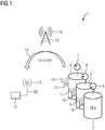
- a switchgear 1 is shown schematically.
- Three SF 6 filled tanks 2, 3, 4 - in this case gas-insulated high-voltage switchgear - each have an analog measuring device 5, 6, 7, which indicates the gas density.
- the arrows in the measuring devices 5, 6, 7 indicate the display of the gas density on an analog scale.
- Each of the containers 2, 3, 4 has an arrangement 8, 10, 12 according to the invention on its gas filling device, which uses the surrounding electromagnetic radiation 19 from a radiation source 18 - a TV transmission mast - for energy generation.
- the arrangements 8, 10, 12 transmit the measured parameters of the gas, in this case the temperature and the gas pressure, via radio connections 9, 11, 13 such as W-LAN to an evaluation device 17.
- the digital transmission of the data is indicated by the arrow 14 and signal 101101001.
- the evaluation device 17 has an antenna 16 for receiving and / or transmitting radio signals 15 and is set up to calculate the density of the gas from the measured parameters gas pressure and temperature. It can be used to determine exactly at what rate gas loss occurs within the container over the course of several measurements over time.
- the evaluation device 17 can use its transmission function to provide electromagnetic radiation for the energy supply of the energy supply devices of the arrangements in addition to the radiation source 18 or instead of the radiation source 18.
- the evaluation device 17 is arranged close to the individual containers, but it could also be arranged anywhere in the world with correspondingly more extensive means of communication, such as an Internet connection.
- an existing container can be retrofitted with the arrangement 8, 10, 12 according to the invention on its usually already existing gas filling device.
- the Figure 2 shows a known closure device 21 for a gas filling device 20 of a container, the gas filling device 20 having a rear side 22 and a front side 23 with a valve. Should the arrangement according to the invention Instead of using the closure device 21 shown to retrofit an existing container, the arrangement according to the invention must be suitable for use with the gas filling device 20.
- FIG. 3 An embodiment of a system 30 according to the invention is shown schematically.
- the area 31 there is a container which is filled with the protective gas SF 6 .
- a conventional gas filling device 20 is attached to the container.
- This has a base 34 with a bulge 35, in which a chamber 37 and a through opening 36 are located. Chamber 37 and through opening 36 form a fluid-conducting connection with the container and therefore contain the gas.
- the chamber is open to the left.
- an arrangement according to the invention is shown, which for better clarity has not yet been pushed fully onto the gas filling device 20 (in the direction of the arrow).
- the arrangement has a jacket 38 and a bushing 39 with sealing means (black dots).
- sealing means black dots
- the jacket 38 encompasses the left part of the base 34 and the bush 39 surrounds the bulge 35, so that the chamber 37 bears against the middle part 40. In this way, the gas SF 6 is present at the middle part of the arrangement during operation of the system.
- the middle part 40 of the arrangement has a gas pressure measuring device and a temperature measuring device with which the gas pressure and temperature of the SF 6 can be determined.
- a computer device for controlling the arrangement and processing of the measured parameters and an energy store can additionally be provided in the middle part.
- An outer part 43 adjoins the middle part 40 and on the one hand has an energy supply device 41 which is suitable for obtaining electrical energy from the surrounding electromagnetic radiation.
- the outer part 43 has a communication device 42, which is suitable for transmitting the measured parameters to an evaluation device.
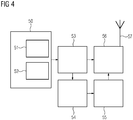
- the Figure 4 shows an embodiment of an arrangement according to the invention with an energy supply device 50 which is suitable for obtaining electrical energy from the surrounding electromagnetic radiation.
- a first energy generation device 51 is used to obtain electrical energy from surrounding radio waves, such as TV signals and / or radio signals, and / or a second energy generation device 52 is used to obtain electrical energy from light.
- the electrical energy obtained is temporarily stored in an energy store 53 and used as required, for example periodically once a day, in order to determine gas pressure and temperature by means of a measuring device 54 and to transmit it to a computer device 55.
- the computer device 55 processes the measured parameters and can calculate the density of the protective gas in the container from the gas pressure and the temperature on the basis of a calculation rule tailored to the protective gas SF 6 .
- the calculated density value and possibly the measured parameters are transmitted via a communication device 56 with antenna 57 for further processing by radio.
- the communication device 56 is also supplied by the energy store 53.
Landscapes
- Physics & Mathematics (AREA)
- General Physics & Mathematics (AREA)
- Health & Medical Sciences (AREA)
- Life Sciences & Earth Sciences (AREA)
- Chemical & Material Sciences (AREA)
- Analytical Chemistry (AREA)
- Biochemistry (AREA)
- General Health & Medical Sciences (AREA)
- Immunology (AREA)
- Pathology (AREA)
- Engineering & Computer Science (AREA)
- Computer Networks & Wireless Communication (AREA)
- Signal Processing (AREA)
- Filling Or Discharging Of Gas Storage Vessels (AREA)
- Arrangements For Transmission Of Measured Signals (AREA)
- Gas-Insulated Switchgears (AREA)
Claims (10)
- Agencement de contrôle de récipients remplis de gaz, comportant :au moins un dispositif de mesure pour la mesure d'au moins un paramètre du gaz dans le récipient,un dispositif (42) de communication, qui est propre à une transmission d'informations sur le gaz à un dispositif d'exploitation,un dispositif (41) d'alimentation en énergie, qui est propre à obtenir de l'énergie électrique à partir du rayonnement électromagnétique ambiant,dans lequel le dispositif (41) d'alimentation en énergie est propre à utiliser du rayonnement électromagnétique dans la bande de fréquence radio et/ou dans la bande de fréquence pour des signaux TV et/ou dans la bande de fréquence pour la téléphonie mobile afin d'obtenir de l'énergie, caractérisé en ce quele au moins un dispositif de mesure comprend un dispositif de mesure de la pression du gaz et un dispositif de mesure de la température, le dispositif d'exploitation étant propre à calculer la masse volumique du gaz à partir des paramètres mesurés, pression du gaz et température, et en ce quel'agencement peut, pour rééquiper un récipient, être mis sur un système de remplissage de récipient par du gaz et en ce que le au moins un dispositif de mesure est prévu dans une partie (40) médiane de l'agencement, qui est voisine du système de remplissage par du gaz avec le récipient rempli de gaz et en ce que l'agencement a une douille (39) qui peut être mise sur le dispositif de remplissage par du gaz, la partie (40) médiane au fond de la douille (39) et une partie (43) extérieure qui est voisine de la partie (40) médiane, eten ce quela partie (43) extérieure a le dispositif (41) d'alimentation en énergie et le dispositif (42) de communication.
- Agencement suivant la revendication 1, caractérisé en ce que le dispositif de communication est propre à la production d'une liaison radio avec le dispositif d'exploitation.
- Agencement suivant la revendication 1 ou 2, caractérisé en ce que le dispositif d'alimentation en énergie est propre à utiliser de la lumière au moyen de cellules solaires pour obtenir de l'énergie.
- Agencement suivant l'une des revendications précédentes, caractérisé en ce qu'un accumulateur d'énergie est prévu pour l'accumulation intermédiaire de l'énergie électrique produite par le dispositif d'alimentation en énergie.
- Agencement suivant l'une des revendications précédentes, caractérisé en ce que le au moins un dispositif de mesure est associé à un système de raccordement propre au raccordement à un récipient.
- Système de contrôle de récipients remplis de gaz, comportant :
un agencement suivant l'une des revendications précédentes et un récipient rempli de gaz. - Système suivant la revendication 6, caractérisé en ce que le récipient est une installation électrique qui est remplie d'un gaz de protection.
- Système suivant la revendication 7, caractérisé en ce que le gaz de protection comprend de l'hexafluorure de soufre.
- Système suivant l'une des revendications 6 à 8, caractérisé en ce que l'agencement est propre à rééquiper un récipient sur son système existant de remplissage par du gaz.
- Procédé de contrôle de récipients remplis de gaz, dans lequel
on obtient, à partir de rayonnement électromagnétique entourant un récipient rempli de gaz, de l'énergie électrique pour l'alimentation en énergie d'au moins un dispositif de mesure et d'un dispositif de communication, et
au moyen du au moins un dispositif de mesure, on mesure au moins un paramètre du gaz dans le récipient, et
on transmet des informations sur le gaz à un dispositif d'exploitation au moyen d'un dispositif (42) de communication,
dans lequel
on mesure les paramètres pression du gaz et température au moyen du au moins un dispositif de mesure, et
à partir des paramètres mesurés, on calcule la masse volumique du gaz, et
on utilise, pour obtenir de l'énergie, pour le rayonnement électromagnétique, la bande de fréquence radio et/ou la bande de fréquence pour des signaux TV et/ou la bande de fréquence pour la téléphonie mobile, et
on met le au moins un dispositif de mesure et le dispositif (42) de communication comme partie d'un agencement de rééquipement d'un récipient sur un dispositif de remplissage de récipient par du gaz, et
l'agencement a une douille (39) qui peut être mise sur le dispositif de remplissage par du gaz, une partie (40) médiane au fond de la douille et une partie (43) extérieure qui est voisine de la partie (40) médiane, et
la partie (43) extérieure a un dispositif (41) d'alimentation en énergie et le dispositif (42) de communication, et
le au moins un dispositif de mesure est prévu dans la partie (40) médiane de l'agencement, la partie (40) médiane étant voisine du système de remplissage par du gaz avec le récipient rempli de gaz.
Applications Claiming Priority (1)
| Application Number | Priority Date | Filing Date | Title |
|---|---|---|---|
| DE102015206873.0A DE102015206873A1 (de) | 2015-04-16 | 2015-04-16 | Anordnung, System und Verfahren für eine Überwachung von gasgefüllten Behältern |
Publications (2)
| Publication Number | Publication Date |
|---|---|
| EP3081907A1 EP3081907A1 (fr) | 2016-10-19 |
| EP3081907B1 true EP3081907B1 (fr) | 2020-07-29 |
Family
ID=56014778
Family Applications (1)
| Application Number | Title | Priority Date | Filing Date |
|---|---|---|---|
| EP16163969.5A Active EP3081907B1 (fr) | 2015-04-16 | 2016-04-06 | Agencement, systeme et procede pour la surveillance de recipients remplis de gaz |
Country Status (4)
| Country | Link |
|---|---|
| US (1) | US10670503B2 (fr) |
| EP (1) | EP3081907B1 (fr) |
| DE (1) | DE102015206873A1 (fr) |
| ES (1) | ES2825717T3 (fr) |
Cited By (1)
| Publication number | Priority date | Publication date | Assignee | Title |
|---|---|---|---|---|
| US12474247B2 (en) | 2021-01-14 | 2025-11-18 | Siemens Energy Global GmbH & Co. KG | Insulating fluid monitoring block and mounting method |
Families Citing this family (4)
| Publication number | Priority date | Publication date | Assignee | Title |
|---|---|---|---|---|
| CN106596329A (zh) * | 2016-12-19 | 2017-04-26 | 华能国际电力股份有限公司玉环电厂 | 基于就地显示仪的gis六氟化硫密度在线监测系统 |
| DE102018209767A1 (de) * | 2018-06-18 | 2019-12-19 | Siemens Aktiengesellschaft | Verfahren, Anordnung und Computerprogrammprodukt zum Überwachen von Verbrauchsmitteln über mehrere Nutzungszyklen |
| CN109725234A (zh) * | 2019-01-24 | 2019-05-07 | 山东欣巽联信息科技有限公司 | 一种基于物联网和审慎原则的开闭所实时健康状态评估方法 |
| CN111189856B (zh) * | 2020-03-15 | 2021-02-26 | 太原理工大学 | 一种采用环境反向散射技术的土壤水分检测方法 |
Citations (1)
| Publication number | Priority date | Publication date | Assignee | Title |
|---|---|---|---|---|
| US6367308B1 (en) * | 1998-12-18 | 2002-04-09 | Alstom | Method of measuring the density of a dielectric gas in a buried metal-clad line |
Family Cites Families (16)
| Publication number | Priority date | Publication date | Assignee | Title |
|---|---|---|---|---|
| DE9316327U1 (de) | 1993-10-26 | 1994-11-03 | Hamburger Gaswerke GmbH, 20097 Hamburg | Druckerfassungs- und Speicherungsmodul für Gasdruckreglerstationen |
| DE19523939C2 (de) | 1995-07-05 | 1999-05-20 | Ernst Dr Med Schaefer | Anlage zur Speicherung und Nutzbarmachung von Solar-, Wind- und/oder Wasserkraftenergie |
| JP2000504553A (ja) * | 1996-01-31 | 2000-04-11 | シーメンス アクチエンゲゼルシヤフト | 閉鎖形設備 |
| DE19703854A1 (de) * | 1997-02-03 | 1998-08-06 | Lange Gmbh Dr Bruno | Multifunktionales Labormeßgerät |
| NL1013884C2 (nl) * | 1999-12-17 | 2001-06-29 | J & M Holding B V | Stelsel voor het meten van een parameter binnen een afgesloten omgeving. |
| JP3579868B2 (ja) * | 2000-05-30 | 2004-10-20 | 株式会社山武 | センサ装置、設定装置、読み出し装置及び物品管理システム |
| US7086593B2 (en) * | 2003-04-30 | 2006-08-08 | The United States Of America As Represented By The Administrator Of The National Aeronautics And Space Administration | Magnetic field response measurement acquisition system |
| US20050008904A1 (en) | 2003-07-11 | 2005-01-13 | Suppes Galen J. | Regenerative fuel cell technology |
| US8437976B2 (en) * | 2004-07-29 | 2013-05-07 | Kulite Semiconductor Products, Inc. | Gas density transducer with a microprocessor executing an algorithm solving Van Der Waal's equation |
| JP2007170555A (ja) | 2005-12-22 | 2007-07-05 | Yazaki Corp | 液化ガス供給装置 |
| JP4957089B2 (ja) * | 2006-06-13 | 2012-06-20 | 富士ゼロックス株式会社 | センサ |
| US8380463B2 (en) * | 2006-11-16 | 2013-02-19 | Endress + Hauser Gmbh + Co. Kg | Apparatus having a modularly constructed, measuring transducer circuit |
| DE102007017632A1 (de) * | 2007-04-13 | 2008-10-16 | Sentec Elektronik Gmbh | Sensoranordnung |
| FR2915821B1 (fr) | 2007-05-03 | 2009-11-20 | Air Liquide | Procede de traitement de donnees relatives a une bouteille de fluide sous pression |
| WO2012140310A1 (fr) * | 2011-04-15 | 2012-10-18 | Upm Rfid Oy | Procédé et appareil permettant de suivre une variable environnementale |
| US9239254B1 (en) * | 2012-04-19 | 2016-01-19 | Maxim Integrated Products, Inc. | Ambient temperature measurement |
-
2015
- 2015-04-16 DE DE102015206873.0A patent/DE102015206873A1/de not_active Withdrawn
-
2016
- 2016-04-06 ES ES16163969T patent/ES2825717T3/es active Active
- 2016-04-06 EP EP16163969.5A patent/EP3081907B1/fr active Active
- 2016-04-18 US US15/131,225 patent/US10670503B2/en active Active
Patent Citations (1)
| Publication number | Priority date | Publication date | Assignee | Title |
|---|---|---|---|---|
| US6367308B1 (en) * | 1998-12-18 | 2002-04-09 | Alstom | Method of measuring the density of a dielectric gas in a buried metal-clad line |
Cited By (1)
| Publication number | Priority date | Publication date | Assignee | Title |
|---|---|---|---|---|
| US12474247B2 (en) | 2021-01-14 | 2025-11-18 | Siemens Energy Global GmbH & Co. KG | Insulating fluid monitoring block and mounting method |
Also Published As
| Publication number | Publication date |
|---|---|
| ES2825717T3 (es) | 2021-05-17 |
| DE102015206873A1 (de) | 2016-10-20 |
| US10670503B2 (en) | 2020-06-02 |
| US20160305862A1 (en) | 2016-10-20 |
| EP3081907A1 (fr) | 2016-10-19 |
Similar Documents
| Publication | Publication Date | Title |
|---|---|---|
| EP3081907B1 (fr) | Agencement, systeme et procede pour la surveillance de recipients remplis de gaz | |
| DE102011079935B4 (de) | Überwachungsvorrichtung für eine Kabelmuffe und Kabelmuffe mit Überwachungsvorrichtung | |
| EP3017342B1 (fr) | Dispositif de transmission pour appareil de mesure et procédé de transmission de données brutes au moyen d'un dispositif de transmission | |
| DE102015105357A1 (de) | Eingebettete drahtlose Sensoren zur Übewachung einer Turbomaschinenkomponente auf einen Defekt | |
| EP2156150B1 (fr) | Procédé pour surveiller l'état d'un dispositif dynamométrique, dispositif dynamométrique et module dynamométrique | |
| DE102015216915A1 (de) | Verfahren und Vorrichtung zur Isolationsfehlersuche mit adaptiver Prüfstrom-Ermittlung | |
| EP2171415A2 (fr) | Ressort pneumatique muni de moyens de mesure, dispositif et procédé de surveillance d'au moins une grandeur de mesure physique observée à l'intérieur d'un ressort pneumatique et/ou sur un ressort pneumatique | |
| DE102016013406A1 (de) | Verfahren zum Betrieb eines Zustandsüberwachungssystems einer Schwingmaschine und Zustandsüberwachungssystem | |
| DE202010016362U1 (de) | Anordnung mit einer übergeordneten Steuereinheit und zumindest einem mit der Steuereinheit verbindbaren intelligenten Feldgerät | |
| EP2947426B1 (fr) | Procédé de fonctionnement d'un point de mesure | |
| DE112008003195T5 (de) | Elektrischer Schaltkreis mit einem physikalischen Übertragungsschicht-Diagnosesystem | |
| EP3928413A1 (fr) | Procédé et système pour surveiller l'état de fonctionnement d'un réseau d'alimentation en énergie | |
| DE112013002386T5 (de) | Einrichtung zum Überprüfen von Datenübertragungen auf zweidrahtigen, kombiniert verbundenen Energie- und Datennetzsystemen für eine Automatisierung | |
| EP4248283B1 (fr) | Module d'affichage et/ou de commande | |
| WO2025228656A1 (fr) | Procédé de fourniture de données de durée de vie | |
| DE102016124796A1 (de) | Sensorkopfmodul zur kontinuierlichen automatisierten Datenerfassung | |
| WO2020193058A1 (fr) | Procédé et système pour surveiller l'état de fonctionnement d'un réseau d'alimentation en énergie | |
| DE102014009354A1 (de) | Verfahren und Vorrichtung zur Fehleranalyse einer Messeinrichtung | |
| DE102014112019B4 (de) | Sensoreinheit zur Temperaturüberwachung sowie zur Temperaturkompensation eines Ultraschallsensors sowie eine Anordnung enthaltend eine Sensoreinheit und einen Ultraschallsensor | |
| DE102008005672B4 (de) | Vorrichtung und Verfahren zum Erfassen von Strukturveränderungen eines Bauteils | |
| WO2018054686A1 (fr) | Dispositif portatif permettant de diagnostiquer un appareil de réglage acheminant un fluide de traitement, et procédé de diagnostic de l'état d'un appareil de réglage acheminant un fluide de traitement | |
| EP3715881B1 (fr) | Procédé d'entretien d'une traversée à haute tension | |
| DE112020006177T5 (de) | Verfahren, Vorrichtung und Anordnung zur Überwachung von elektrischen Wechselstromgeräten | |
| AT528102B1 (de) | System und Verfahren zum Überwachen von Teilentladungsaktivität | |
| EP4182762B1 (fr) | Dispositif de commande de soupapepour une installation de traitement et procédé de diagnostic correspondant |
Legal Events
| Date | Code | Title | Description |
|---|---|---|---|
| PUAI | Public reference made under article 153(3) epc to a published international application that has entered the european phase |
Free format text: ORIGINAL CODE: 0009012 |
|
| AK | Designated contracting states |
Kind code of ref document: A1 Designated state(s): AL AT BE BG CH CY CZ DE DK EE ES FI FR GB GR HR HU IE IS IT LI LT LU LV MC MK MT NL NO PL PT RO RS SE SI SK SM TR |
|
| AX | Request for extension of the european patent |
Extension state: BA ME |
|
| STAA | Information on the status of an ep patent application or granted ep patent |
Free format text: STATUS: REQUEST FOR EXAMINATION WAS MADE |
|
| 17P | Request for examination filed |
Effective date: 20170418 |
|
| RBV | Designated contracting states (corrected) |
Designated state(s): AL AT BE BG CH CY CZ DE DK EE ES FI FR GB GR HR HU IE IS IT LI LT LU LV MC MK MT NL NO PL PT RO RS SE SI SK SM TR |
|
| RAP1 | Party data changed (applicant data changed or rights of an application transferred) |
Owner name: SIEMENS AKTIENGESELLSCHAFT |
|
| STAA | Information on the status of an ep patent application or granted ep patent |
Free format text: STATUS: EXAMINATION IS IN PROGRESS |
|
| 17Q | First examination report despatched |
Effective date: 20180815 |
|
| GRAP | Despatch of communication of intention to grant a patent |
Free format text: ORIGINAL CODE: EPIDOSNIGR1 |
|
| STAA | Information on the status of an ep patent application or granted ep patent |
Free format text: STATUS: GRANT OF PATENT IS INTENDED |
|
| INTG | Intention to grant announced |
Effective date: 20200309 |
|
| GRAS | Grant fee paid |
Free format text: ORIGINAL CODE: EPIDOSNIGR3 |
|
| GRAA | (expected) grant |
Free format text: ORIGINAL CODE: 0009210 |
|
| STAA | Information on the status of an ep patent application or granted ep patent |
Free format text: STATUS: THE PATENT HAS BEEN GRANTED |
|
| AK | Designated contracting states |
Kind code of ref document: B1 Designated state(s): AL AT BE BG CH CY CZ DE DK EE ES FI FR GB GR HR HU IE IS IT LI LT LU LV MC MK MT NL NO PL PT RO RS SE SI SK SM TR |
|
| REG | Reference to a national code |
Ref country code: CH Ref legal event code: EP |
|
| REG | Reference to a national code |
Ref country code: AT Ref legal event code: REF Ref document number: 1296323 Country of ref document: AT Kind code of ref document: T Effective date: 20200815 |
|
| REG | Reference to a national code |
Ref country code: IE Ref legal event code: FG4D Free format text: LANGUAGE OF EP DOCUMENT: GERMAN |
|
| REG | Reference to a national code |
Ref country code: DE Ref legal event code: R096 Ref document number: 502016010621 Country of ref document: DE |
|
| REG | Reference to a national code |
Ref country code: CH Ref legal event code: NV Representative=s name: SIEMENS SCHWEIZ AG, CH |
|
| REG | Reference to a national code |
Ref country code: FI Ref legal event code: FGE |
|
| REG | Reference to a national code |
Ref country code: NL Ref legal event code: FP |
|
| REG | Reference to a national code |
Ref country code: SE Ref legal event code: TRGR |
|
| REG | Reference to a national code |
Ref country code: LT Ref legal event code: MG4D |
|
| REG | Reference to a national code |
Ref country code: DE Ref legal event code: R081 Ref document number: 502016010621 Country of ref document: DE Owner name: SIEMENS ENERGY GLOBAL GMBH & CO. KG, DE Free format text: FORMER OWNER: SIEMENS AKTIENGESELLSCHAFT, 80333 MUENCHEN, DE |
|
| RAP2 | Party data changed (patent owner data changed or rights of a patent transferred) |
Owner name: SIEMENS ENERGY GLOBAL GMBH & CO. KG |
|
| PG25 | Lapsed in a contracting state [announced via postgrant information from national office to epo] |
Ref country code: GR Free format text: LAPSE BECAUSE OF FAILURE TO SUBMIT A TRANSLATION OF THE DESCRIPTION OR TO PAY THE FEE WITHIN THE PRESCRIBED TIME-LIMIT Effective date: 20201030 Ref country code: LT Free format text: LAPSE BECAUSE OF FAILURE TO SUBMIT A TRANSLATION OF THE DESCRIPTION OR TO PAY THE FEE WITHIN THE PRESCRIBED TIME-LIMIT Effective date: 20200729 Ref country code: HR Free format text: LAPSE BECAUSE OF FAILURE TO SUBMIT A TRANSLATION OF THE DESCRIPTION OR TO PAY THE FEE WITHIN THE PRESCRIBED TIME-LIMIT Effective date: 20200729 Ref country code: PT Free format text: LAPSE BECAUSE OF FAILURE TO SUBMIT A TRANSLATION OF THE DESCRIPTION OR TO PAY THE FEE WITHIN THE PRESCRIBED TIME-LIMIT Effective date: 20201130 Ref country code: NO Free format text: LAPSE BECAUSE OF FAILURE TO SUBMIT A TRANSLATION OF THE DESCRIPTION OR TO PAY THE FEE WITHIN THE PRESCRIBED TIME-LIMIT Effective date: 20201029 Ref country code: BG Free format text: LAPSE BECAUSE OF FAILURE TO SUBMIT A TRANSLATION OF THE DESCRIPTION OR TO PAY THE FEE WITHIN THE PRESCRIBED TIME-LIMIT Effective date: 20201029 |
|
| PG25 | Lapsed in a contracting state [announced via postgrant information from national office to epo] |
Ref country code: PL Free format text: LAPSE BECAUSE OF FAILURE TO SUBMIT A TRANSLATION OF THE DESCRIPTION OR TO PAY THE FEE WITHIN THE PRESCRIBED TIME-LIMIT Effective date: 20200729 Ref country code: LV Free format text: LAPSE BECAUSE OF FAILURE TO SUBMIT A TRANSLATION OF THE DESCRIPTION OR TO PAY THE FEE WITHIN THE PRESCRIBED TIME-LIMIT Effective date: 20200729 Ref country code: RS Free format text: LAPSE BECAUSE OF FAILURE TO SUBMIT A TRANSLATION OF THE DESCRIPTION OR TO PAY THE FEE WITHIN THE PRESCRIBED TIME-LIMIT Effective date: 20200729 Ref country code: IS Free format text: LAPSE BECAUSE OF FAILURE TO SUBMIT A TRANSLATION OF THE DESCRIPTION OR TO PAY THE FEE WITHIN THE PRESCRIBED TIME-LIMIT Effective date: 20201129 |
|
| PG25 | Lapsed in a contracting state [announced via postgrant information from national office to epo] |
Ref country code: DK Free format text: LAPSE BECAUSE OF FAILURE TO SUBMIT A TRANSLATION OF THE DESCRIPTION OR TO PAY THE FEE WITHIN THE PRESCRIBED TIME-LIMIT Effective date: 20200729 Ref country code: CZ Free format text: LAPSE BECAUSE OF FAILURE TO SUBMIT A TRANSLATION OF THE DESCRIPTION OR TO PAY THE FEE WITHIN THE PRESCRIBED TIME-LIMIT Effective date: 20200729 Ref country code: RO Free format text: LAPSE BECAUSE OF FAILURE TO SUBMIT A TRANSLATION OF THE DESCRIPTION OR TO PAY THE FEE WITHIN THE PRESCRIBED TIME-LIMIT Effective date: 20200729 Ref country code: SM Free format text: LAPSE BECAUSE OF FAILURE TO SUBMIT A TRANSLATION OF THE DESCRIPTION OR TO PAY THE FEE WITHIN THE PRESCRIBED TIME-LIMIT Effective date: 20200729 Ref country code: EE Free format text: LAPSE BECAUSE OF FAILURE TO SUBMIT A TRANSLATION OF THE DESCRIPTION OR TO PAY THE FEE WITHIN THE PRESCRIBED TIME-LIMIT Effective date: 20200729 |
|
| REG | Reference to a national code |
Ref country code: DE Ref legal event code: R097 Ref document number: 502016010621 Country of ref document: DE |
|
| REG | Reference to a national code |
Ref country code: ES Ref legal event code: FG2A Ref document number: 2825717 Country of ref document: ES Kind code of ref document: T3 Effective date: 20210517 |
|
| PG25 | Lapsed in a contracting state [announced via postgrant information from national office to epo] |
Ref country code: AL Free format text: LAPSE BECAUSE OF FAILURE TO SUBMIT A TRANSLATION OF THE DESCRIPTION OR TO PAY THE FEE WITHIN THE PRESCRIBED TIME-LIMIT Effective date: 20200729 |
|
| PLBE | No opposition filed within time limit |
Free format text: ORIGINAL CODE: 0009261 |
|
| STAA | Information on the status of an ep patent application or granted ep patent |
Free format text: STATUS: NO OPPOSITION FILED WITHIN TIME LIMIT |
|
| PG25 | Lapsed in a contracting state [announced via postgrant information from national office to epo] |
Ref country code: SK Free format text: LAPSE BECAUSE OF FAILURE TO SUBMIT A TRANSLATION OF THE DESCRIPTION OR TO PAY THE FEE WITHIN THE PRESCRIBED TIME-LIMIT Effective date: 20200729 |
|
| 26N | No opposition filed |
Effective date: 20210430 |
|
| PG25 | Lapsed in a contracting state [announced via postgrant information from national office to epo] |
Ref country code: SI Free format text: LAPSE BECAUSE OF FAILURE TO SUBMIT A TRANSLATION OF THE DESCRIPTION OR TO PAY THE FEE WITHIN THE PRESCRIBED TIME-LIMIT Effective date: 20200729 |
|
| PGFP | Annual fee paid to national office [announced via postgrant information from national office to epo] |
Ref country code: BE Payment date: 20210420 Year of fee payment: 6 |
|
| PG25 | Lapsed in a contracting state [announced via postgrant information from national office to epo] |
Ref country code: MC Free format text: LAPSE BECAUSE OF FAILURE TO SUBMIT A TRANSLATION OF THE DESCRIPTION OR TO PAY THE FEE WITHIN THE PRESCRIBED TIME-LIMIT Effective date: 20200729 |
|
| PGFP | Annual fee paid to national office [announced via postgrant information from national office to epo] |
Ref country code: ES Payment date: 20210723 Year of fee payment: 6 |
|
| REG | Reference to a national code |
Ref country code: GB Ref legal event code: 732E Free format text: REGISTERED BETWEEN 20211202 AND 20211209 |
|
| PG25 | Lapsed in a contracting state [announced via postgrant information from national office to epo] |
Ref country code: LU Free format text: LAPSE BECAUSE OF NON-PAYMENT OF DUE FEES Effective date: 20210406 |
|
| PG25 | Lapsed in a contracting state [announced via postgrant information from national office to epo] |
Ref country code: IE Free format text: LAPSE BECAUSE OF NON-PAYMENT OF DUE FEES Effective date: 20210406 |
|
| PG25 | Lapsed in a contracting state [announced via postgrant information from national office to epo] |
Ref country code: IS Free format text: LAPSE BECAUSE OF FAILURE TO SUBMIT A TRANSLATION OF THE DESCRIPTION OR TO PAY THE FEE WITHIN THE PRESCRIBED TIME-LIMIT Effective date: 20201129 |
|
| REG | Reference to a national code |
Ref country code: AT Ref legal event code: PC Ref document number: 1296323 Country of ref document: AT Kind code of ref document: T Owner name: SIEMENS ENERGY GLOBAL GMBH & CO. KG, DE Effective date: 20221018 |
|
| REG | Reference to a national code |
Ref country code: BE Ref legal event code: MM Effective date: 20220430 |
|
| REG | Reference to a national code |
Ref country code: NL Ref legal event code: PD Owner name: SIEMENS ENERGY GLOBAL GMBH & CO. KG; DE Free format text: DETAILS ASSIGNMENT: CHANGE OF OWNER(S), ASSIGNMENT; FORMER OWNER NAME: SIEMENS AKTIENGESELLSCHAFT Effective date: 20230125 |
|
| PG25 | Lapsed in a contracting state [announced via postgrant information from national office to epo] |
Ref country code: BE Free format text: LAPSE BECAUSE OF NON-PAYMENT OF DUE FEES Effective date: 20220430 |
|
| REG | Reference to a national code |
Ref country code: ES Ref legal event code: FD2A Effective date: 20230526 |
|
| PG25 | Lapsed in a contracting state [announced via postgrant information from national office to epo] |
Ref country code: HU Free format text: LAPSE BECAUSE OF FAILURE TO SUBMIT A TRANSLATION OF THE DESCRIPTION OR TO PAY THE FEE WITHIN THE PRESCRIBED TIME-LIMIT; INVALID AB INITIO Effective date: 20160406 |
|
| PG25 | Lapsed in a contracting state [announced via postgrant information from national office to epo] |
Ref country code: CY Free format text: LAPSE BECAUSE OF FAILURE TO SUBMIT A TRANSLATION OF THE DESCRIPTION OR TO PAY THE FEE WITHIN THE PRESCRIBED TIME-LIMIT Effective date: 20200729 |
|
| PG25 | Lapsed in a contracting state [announced via postgrant information from national office to epo] |
Ref country code: ES Free format text: LAPSE BECAUSE OF NON-PAYMENT OF DUE FEES Effective date: 20220407 |
|
| PG25 | Lapsed in a contracting state [announced via postgrant information from national office to epo] |
Ref country code: MK Free format text: LAPSE BECAUSE OF FAILURE TO SUBMIT A TRANSLATION OF THE DESCRIPTION OR TO PAY THE FEE WITHIN THE PRESCRIBED TIME-LIMIT Effective date: 20200729 |
|
| PG25 | Lapsed in a contracting state [announced via postgrant information from national office to epo] |
Ref country code: TR Free format text: LAPSE BECAUSE OF FAILURE TO SUBMIT A TRANSLATION OF THE DESCRIPTION OR TO PAY THE FEE WITHIN THE PRESCRIBED TIME-LIMIT Effective date: 20200729 |
|
| PG25 | Lapsed in a contracting state [announced via postgrant information from national office to epo] |
Ref country code: MT Free format text: LAPSE BECAUSE OF FAILURE TO SUBMIT A TRANSLATION OF THE DESCRIPTION OR TO PAY THE FEE WITHIN THE PRESCRIBED TIME-LIMIT Effective date: 20200729 |
|
| PGFP | Annual fee paid to national office [announced via postgrant information from national office to epo] |
Ref country code: NL Payment date: 20250424 Year of fee payment: 10 |
|
| PGFP | Annual fee paid to national office [announced via postgrant information from national office to epo] |
Ref country code: FI Payment date: 20250424 Year of fee payment: 10 |
|
| PGFP | Annual fee paid to national office [announced via postgrant information from national office to epo] |
Ref country code: DE Payment date: 20250428 Year of fee payment: 10 |
|
| PGFP | Annual fee paid to national office [announced via postgrant information from national office to epo] |
Ref country code: IT Payment date: 20250422 Year of fee payment: 10 |
|
| PGFP | Annual fee paid to national office [announced via postgrant information from national office to epo] |
Ref country code: FR Payment date: 20250424 Year of fee payment: 10 |
|
| PGFP | Annual fee paid to national office [announced via postgrant information from national office to epo] |
Ref country code: CH Payment date: 20250501 Year of fee payment: 10 |
|
| PGFP | Annual fee paid to national office [announced via postgrant information from national office to epo] |
Ref country code: AT Payment date: 20250417 Year of fee payment: 10 |
|
| PGFP | Annual fee paid to national office [announced via postgrant information from national office to epo] |
Ref country code: SE Payment date: 20250424 Year of fee payment: 10 |
|
| PGFP | Annual fee paid to national office [announced via postgrant information from national office to epo] |
Ref country code: GB Payment date: 20260323 Year of fee payment: 11 |