EP3081908A1 - Method and device for detecting the presence of a liquid in a gas flow - Google Patents
Method and device for detecting the presence of a liquid in a gas flow Download PDFInfo
- Publication number
- EP3081908A1 EP3081908A1 EP16159770.3A EP16159770A EP3081908A1 EP 3081908 A1 EP3081908 A1 EP 3081908A1 EP 16159770 A EP16159770 A EP 16159770A EP 3081908 A1 EP3081908 A1 EP 3081908A1
- Authority
- EP
- European Patent Office
- Prior art keywords
- gas
- measuring
- stage
- ultrasonic
- paths
- Prior art date
- Legal status (The legal status is an assumption and is not a legal conclusion. Google has not performed a legal analysis and makes no representation as to the accuracy of the status listed.)
- Granted
Links
Images

Classifications
-
- G—PHYSICS
- G01—MEASURING; TESTING
- G01F—MEASURING VOLUME, VOLUME FLOW, MASS FLOW OR LIQUID LEVEL; METERING BY VOLUME
- G01F1/00—Measuring the volume flow or mass flow of fluid or fluent solid material wherein the fluid passes through a meter in a continuous flow
- G01F1/66—Measuring the volume flow or mass flow of fluid or fluent solid material wherein the fluid passes through a meter in a continuous flow by measuring frequency, phase shift or propagation time of electromagnetic or other waves, e.g. using ultrasonic flowmeters
- G01F1/667—Arrangements of transducers for ultrasonic flowmeters; Circuits for operating ultrasonic flowmeters
-
- G—PHYSICS
- G01—MEASURING; TESTING
- G01F—MEASURING VOLUME, VOLUME FLOW, MASS FLOW OR LIQUID LEVEL; METERING BY VOLUME
- G01F1/00—Measuring the volume flow or mass flow of fluid or fluent solid material wherein the fluid passes through a meter in a continuous flow
- G01F1/66—Measuring the volume flow or mass flow of fluid or fluent solid material wherein the fluid passes through a meter in a continuous flow by measuring frequency, phase shift or propagation time of electromagnetic or other waves, e.g. using ultrasonic flowmeters
- G01F1/662—Constructional details
-
- G—PHYSICS
- G01—MEASURING; TESTING
- G01F—MEASURING VOLUME, VOLUME FLOW, MASS FLOW OR LIQUID LEVEL; METERING BY VOLUME
- G01F1/00—Measuring the volume flow or mass flow of fluid or fluent solid material wherein the fluid passes through a meter in a continuous flow
- G01F1/66—Measuring the volume flow or mass flow of fluid or fluent solid material wherein the fluid passes through a meter in a continuous flow by measuring frequency, phase shift or propagation time of electromagnetic or other waves, e.g. using ultrasonic flowmeters
- G01F1/667—Arrangements of transducers for ultrasonic flowmeters; Circuits for operating ultrasonic flowmeters
- G01F1/668—Compensating or correcting for variations in velocity of sound
-
- G—PHYSICS
- G01—MEASURING; TESTING
- G01F—MEASURING VOLUME, VOLUME FLOW, MASS FLOW OR LIQUID LEVEL; METERING BY VOLUME
- G01F1/00—Measuring the volume flow or mass flow of fluid or fluent solid material wherein the fluid passes through a meter in a continuous flow
- G01F1/002—Measuring the volume flow or mass flow of fluid or fluent solid material wherein the fluid passes through a meter in a continuous flow wherein the flow is in an open channel
-
- G—PHYSICS
- G01—MEASURING; TESTING
- G01F—MEASURING VOLUME, VOLUME FLOW, MASS FLOW OR LIQUID LEVEL; METERING BY VOLUME
- G01F1/00—Measuring the volume flow or mass flow of fluid or fluent solid material wherein the fluid passes through a meter in a continuous flow
- G01F1/66—Measuring the volume flow or mass flow of fluid or fluent solid material wherein the fluid passes through a meter in a continuous flow by measuring frequency, phase shift or propagation time of electromagnetic or other waves, e.g. using ultrasonic flowmeters
-
- G—PHYSICS
- G01—MEASURING; TESTING
- G01F—MEASURING VOLUME, VOLUME FLOW, MASS FLOW OR LIQUID LEVEL; METERING BY VOLUME
- G01F1/00—Measuring the volume flow or mass flow of fluid or fluent solid material wherein the fluid passes through a meter in a continuous flow
- G01F1/74—Devices for measuring flow of a fluid or flow of a fluent solid material in suspension in another fluid
-
- G—PHYSICS
- G01—MEASURING; TESTING
- G01N—INVESTIGATING OR ANALYSING MATERIALS BY DETERMINING THEIR CHEMICAL OR PHYSICAL PROPERTIES
- G01N29/00—Investigating or analysing materials by the use of ultrasonic, sonic or infrasonic waves; Visualisation of the interior of objects by transmitting ultrasonic or sonic waves through the object
- G01N29/02—Analysing fluids
- G01N29/024—Analysing fluids by measuring propagation velocity or propagation time of acoustic waves
Definitions
- the invention relates to a method for detecting the presence of liquid in a gas stream flowing in a pipeline and to an ultrasonic flowmeter with which this method is carried out.
- ultrasonic meters are used for flow measurement.
- Such is from the EP 2 428 776 B1 known and has paired ultrasonic transducers, each pair defining a measuring path which is at a non-perpendicular angle to the longitudinal axis (flow direction), so that the transmitted and received ultrasonic signals propagate along the measuring paths at a certain angle other than 90 ° to the flow direction.
- the measurement principle consists in a determination of a transit time difference between two such ultrasonic signals, which run on a measurement path in the opposite direction and thus once have a component in the flow direction and once a component against the flow direction. From the measured transit time difference, the flow rate can be calculated and with knowledge of the pipe cross-section of the flow.
- z. B. be used on large natural gas pipelines to determine the amount of gas passed, become very high measurement accuracies required, since even the smallest deviations in the flow measurement with the huge amounts of natural gas can make big differences in the monetary equivalent.
- both flow velocities are the same and also have the same degree of turbulence, with turbulence in the EP 2 428 776 B1 is defined as the statistical dispersion of the individual values of flow velocities on one level. If one then forms the ratio of the turbulences from the two planes and the ratio of the flow velocities of the gas on the two planes, these ratios are ideally equal to 1. If deviations of 1 occur, this is regularly an indication of the presence of liquid. because liquid deposits at the bottom of the pipeline and therefore influences the lower measuring path more than the more distant upper measuring path. In this way, two indicators are obtained, on which one can conclude on the presence of liquid.
- a liquid warning signal is then output if an invalid reading is provided in the first stage, or if the ratio in the second stage deviates by more than a predetermined tolerance value of 1, or if in the third stage the ratio of sonic velocities is greater than one given tolerance value of 1 deviates.
- the gradation has the advantage that relatively quickly, z. B. already in the first stage, a fluid accumulation can be detected.
- the recognition principle of the second stage is in principle from the EP 2 428 776 B1 known.
- the third stage is new. It is actually expected that the accumulation of fluid away from a measuring path does not influence the speed of sound in the gas, because the speed of sound in the gas is independent of turbulence because it is only a material property.
- the first level is most insensitive but can be evaluated fastest. If only the lowest measuring path does not provide a measurement of the flow velocity of the gas, it is inside the liquid. A further evaluation on the other two levels is then no longer necessary.
- the second stage in which ratios of turbulence are formed, is more sensitive than the determination from the first stage. If liquid is detected in the second stage because the determined ratio deviates too much from 1, this is an indication of the presence of liquid and the third stage can be omitted.
- the ratio of the sound velocities of a pair of measurement paths is determined. It has been found that the ratio of sound velocities appears to be most sensitive to the presence of liquid in the pipe section. At a minimum, it has been found in practice that this ratio responds to cases that are not detected in the first two stages, so this method can be applied in the last step and smaller quantities of fluid than heretofore possible can be detected.
- a turbulence value is defined as a standard deviation over a plurality of measurements of the flow velocity of the gas on a measurement path, as in principle from US Pat EP 2 428 776 B1 known.
- the method for detecting the presence of liquid actually makes sense only when a gas flow is present, it is provided in a further development of the invention that it is checked before the first step whether the flow velocity of the gas exceeds a minimum value and the Fluid detection steps are not performed until the minimum level is exceeded.
- This minimum value can be determined on any of the measurement paths. Preferably, the minimum value at the upper level could be determined because there the presence of liquid is unlikely. But it should not be the lowest measurement path, because there is the highest probability of liquid.
- the method according to the invention can manage with a pair of measuring paths. But if there are two or more pairs of measurement paths, which then necessarily have to be arranged at different heights, a more accurate sampling of the beam profile can take place. In addition, if one measuring path fails, one or more other pairs of measuring paths can be avoided.
- measurements of different pairs of measuring paths can be used in the second and / or third step.
- a suitable combination of the measurements can result in a higher accuracy.
- a device 10 according to the invention has a measuring sensor 12 which consists of a pipe section 13 arranged between connecting flanges 14 and 16.
- the pipe section 13 is preferably formed in its interior circular with a nominal diameter D, corresponding to a to be connected to the connecting flanges 14 and 16, not shown piping for a gas.
- the device 10 in a tube wall 18 pairs of oppositely arranged ultrasonic transducers 20, 22, 24, 26, of which in the drawing ( FIGS. 2 and 3 ) are shown only a few and are also referred to simply as probes below.
- the ultrasonic transducers define measurement paths 30, 32, 34, 36 as will be described below ( Fig. 4 ).
- the device 10 has an evaluation unit 70, which can be attached to the sensor 12 via a mounting flange. By means of suitable cable connections, which are not shown in the drawing, the probes can be connected to the evaluation unit 70.
- the Device according to the invention for measuring the flow velocity and / or the flow rate of a fluid is preferably used as a gas meter.
- the probes 20, 22, 24, 26 are held in probe receptacles 40, 42, 44, 46 (FIG. FIGS. 2 and 3 ), which are formed as bores in two flat receiving surfaces 56 and 58 of the tube wall 18.
- the receiving surfaces 56 and 58 are parallel to each other and are at an angle not equal to 0 ° to the central axis 60 of the pipe section 13, which also forms the Meßaufillon- and flow axis arranged ( FIGS. 2 and 3 ).
- Respective probe receptacles 40-42, 44-46 are aligned with one another, so that the probes 20, 22, 24, 26 inserted into the probe receptacles are aligned with one another and define the measurement paths 30, 32, 34, 36 ( Fig. 4 ).
- the probes send and receive ultrasound signals in a straight line in their longitudinal direction along the respective measuring path 30, 32, 34, 36.
- all measuring paths of this embodiment run parallel to one another and lie in a common vertical plane S (FIG. Fig. 4 ).
- Each measuring path is at an angle ⁇ to a plane Ev, which extends perpendicular to the central axis 60 and flow direction 72.
- the gas flow flowing through the interior of the measuring transducer 12 is determined in a known manner by first determining the flow velocity of the gas by measuring a transit time difference of ultrasonic signals which run in both directions on a measuring path and thus have a component in and against the flow direction becomes. From the flow velocity can be calculated with knowledge of the pipe cross section of the flow.
- the ultrasonic transducers serve both as a transmitter and as a receiver, so that each measuring path is used by the ultrasonic signals in both directions.
- the speed of sound SoS Speed Of Sound
- the speed of sound SoS is namely the mean of the Speeds of two ultrasound signals running in the opposite direction, ie twice the distance between the two ultrasound transducers divided by the sum of the two transit times back and forth.
- a measuring path In the ideal case of an undisturbed, homogeneous, laminar or turbulent flow, a measuring path would be sufficient to determine the flow velocity and thus the flow.
- a plurality of measuring paths are provided which scan the flow profile at different locations, that is, at different distances from the sensor axis 60. From the individual results for the measuring paths 30, 32, 34, 36 results through suitable integration process the flow.
- the measuring paths 30, 32, 34, 36 are thus arranged one above the other in parallel, horizontal planes Eu1, Eu2, Eo1, Eo2.
- the invention now requires a further special arrangement of the measuring paths.
- Two measuring paths of equal length always form a pair of measuring paths.
- the measuring paths 30 and 36 and 32 and 34 each form a pair.
- the two measurement paths are of equal length, parallel to each other, and extend in separate horizontal planes Eu1 and Eo1, and Eu2 and Eo2, respectively.
- Each horizontal plane of a pair is displaced in the vertical direction by a same, predefined distance d1 or d2 with respect to the central axis 60, so that one of the planes Eo1 and Eo2 is located in an upper region above the central axis 60 and the other plane Eu1 or Eu1 Eu2 is located in a lower region below the central axis 60.
- the method according to the invention now relates to the detection of liquid 50 in the pipe section 13. For this purpose, only the measurements that are available anyway for the flow determination are used.
- the procedure is as described below and as in Fig. 5 shown schematically from:
- step 100 it is first checked in step 100 whether there is sufficient gas flow at all, because if the flow velocity of the gas does not exceed a minimum value, ie if there is no flow or too slow, the method will make no sense. Then it is not important whether a liquid 50 is present.
- This minimum value can theoretically be determined on any of the measurement paths. Preferably, the minimum value should be determined at the highest level, because there the presence of liquid is the least likely. In any case, it should not be taken the lowest measuring path, because there is the highest probability of liquid.
- a following step 102 (first stage), it is checked whether the lowest measuring path 30 delivers a valid measured value for the flow velocity of the gas. If so much liquid 50 exists in the pipe section 13 that the liquid level is above the lowest level Eu1, then the complete measuring path lies in the liquid. It would then for the speed of sound SoS nonsense for gas and thus invalid value measured and invalidate the measurement of a flow velocity. If the presence of liquid has been determined in this step 102, a liquid warning signal is output. The subsequent steps are then no longer necessary.
- a turbulence value is determined for each of the two measurement paths of a pair from a multiple measurement of the flow velocities on a measurement path in one direction and the ratio of the two turbulence values is formed.
- the turbulence value can be z. B. be defined by the standard deviation over several measurements of the flow velocity on a measurement path in one direction. If the flow is highly turbulent, the flow velocity will be more scattered than in a less turbulent flow. It is then checked whether the ratio of the turbulence values deviates by more than a predetermined tolerance value of 1. Without liquid 50 in the pipe section 13, the ratio should be 1 or at least very close to 1.
- the ratio deviates by more than 10%, for example, this may indicate the presence of fluid. How large which should be tolerance values, must be determined empirically. The tolerance values can also be different up and down. For example, they could be such that the ratio should be between 0.9 and 1.15. If the presence of liquid has been determined in this step 104, a liquid warning signal is output. The subsequent step is then no longer necessary.
- a step 106 the respective speed of sound SoS is determined on both measuring paths of a pair and the ratio of the two speeds of sound is formed. It is then tested analogously as in the turbulence values, whether the ratio of the sound velocities differs by more than a predetermined tolerance value of 1. As an example again numbers are called. Limits to the ratio could be, for example, 0.999 and 1.001.
- the method according to the invention is preferably carried out permanently and the three stages are processed cyclically one after the other.
Landscapes
- Physics & Mathematics (AREA)
- General Physics & Mathematics (AREA)
- Electromagnetism (AREA)
- Fluid Mechanics (AREA)
- Measuring Volume Flow (AREA)
- Life Sciences & Earth Sciences (AREA)
- Health & Medical Sciences (AREA)
- Chemical & Material Sciences (AREA)
- Analytical Chemistry (AREA)
- Biochemistry (AREA)
- General Health & Medical Sciences (AREA)
- Immunology (AREA)
- Pathology (AREA)
- Acoustics & Sound (AREA)
Abstract
Die Erfindung betrifft ein Verfahren zum Erkennen des Vorhandenseins von Flüssigkeit (50) in einem in einer Rohrleitung strömenden Gasstrom, unter Verwendung eines Ultraschalldurchflussmessgeräts (10), wobei Messpfade paarweise vorgesehen sind, die vertikal um eine gleiche vordefinierte Distanz bezüglich der Mittelachse verschoben sind, so dass einer in einem oberen Bereich oberhalb der Mittelachse und einer unterhalb der Mittelachse gelegen ist und wobei in einer ersten Stufe (102) geprüft wird, ob der unterste Messpfad (30) einen gültigen Messwert für die Strömungsgeschwindigkeit des Gases liefert, und in einer zweiten Stufe (104) ein Turbulenzwert für jeden Messpfad (30, 36; 32, 34) eines Paares ermittelt wird und das Verhältnis der beiden Turbulenzwerte gebildet wird und in einer dritten Stufe (106) die jeweilige Schallgeschwindigkeit (SoS) auf beiden Messpfaden (30, 36; 32, 34) eines Paares ermittelt wird und das Verhältnis der beiden Schallgeschwindigkeiten (SoS) gebildet wird, und ein Flüssigkeitswarnsignal ausgegeben wird, wenn in der ersten Stufe ein ungültiger Messwert geliefert wird, oder wenn in der zweiten Stufe das Verhältnis der Turbulenzwerte um mehr als einen vorgegebenen Toleranzwert von 1 abweicht, oder wenn in der dritten Stufe das Verhältnis der Schallgeschwindigkeiten um mehr als einen vorgegebenen Toleranzwert von 1 abweicht.The invention relates to a method for detecting the presence of liquid (50) in a gas stream flowing in a pipeline, using an ultrasonic flowmeter (10), wherein measuring paths are provided in pairs, which are vertically displaced by an equal predefined distance with respect to the central axis, so in that one is located in an upper area above the central axis and one below the central axis and in a first stage (102) it is checked whether the lowest measuring path (30) provides a valid measured value for the flow velocity of the gas, and in a second stage (104) a turbulence value for each measuring path (30, 36, 32, 34) of a pair is determined and the ratio of the two turbulence values is formed and in a third stage (106) the respective speed of sound (SoS) on both measuring paths (30, 36 ; 32, 34) of a pair is determined and the ratio of the two sound velocities (SoS) gebil det, and a liquid warning signal is output if an invalid reading is provided in the first stage, or if in the second stage the ratio of turbulence values deviates by more than a predetermined tolerance value of 1, or if in the third stage the ratio of sonic velocities deviates by more than a predetermined tolerance value of 1.
Description
Die Erfindung betrifft ein Verfahren zum Erkennen des Vorhandenseins von Flüssigkeit in einem in einer Rohrleitung strömenden Gasstrom und ein Ultraschalldurchflussmessgerät, mit dem dieses Verfahren durchgeführt wird.The invention relates to a method for detecting the presence of liquid in a gas stream flowing in a pipeline and to an ultrasonic flowmeter with which this method is carried out.
In der Prozessdurchflussmesstechnik sind verschiedene Messverfahren und Messvorrichtungen bekannt. Zunehmend werden für die Durchflussmessung Ultraschallzähler eingesetzt. Ein solcher ist aus der
Bei derartigen Durchflussmessgeräten, die z. B. an großen Erdgasleitungen eingesetzt werden, um die durchgeleitete Gasmenge zu bestimmen, werden sehr hohe Messgenauigkeiten gefordert, da bereits kleinste Abweichungen in der Durchflussmessung bei den gewaltigen Erdgasmengen große Differenzen in dem monetären Gegenwert ausmachen können.In such flow meters, z. B. be used on large natural gas pipelines to determine the amount of gas passed, become very high measurement accuracies required, since even the smallest deviations in the flow measurement with the huge amounts of natural gas can make big differences in the monetary equivalent.
Ein Faktor, der zur Verfälschung einer Messung beiträgt, ist das Vorhandensein von Flüssigkeit in der Rohrleitung. Es sollte somit frühzeitig erkannt werden, wenn Flüssigkeit im Messbereich vorliegt, damit die Messergebnisse entweder richtig bewertet werden können oder sogar entsprechende Gegenmaßnahmen getroffen werden können.One factor that contributes to the falsification of a measurement is the presence of liquid in the pipeline. It should therefore be detected early, if there is liquid in the measuring range, so that the measurement results can either be properly assessed or even appropriate countermeasures can be taken.
Dazu ist es aus der
Obwohl diese Lösung schon gute Ergebnisse liefert, ist es dennoch wünschenswert, noch bessere Indikatoren zu haben, die empfindlicher sind, und/oder auf weitere Strömungen ansprechen.Although this solution already gives good results, it is still desirable to have even better indicators that are more sensitive and / or responsive to other flows.
Ausgehend von diesem Stand der Technik ist es daher Aufgabe der Erfindung, ein Verfahren und Vorrichtung bereitzustellen, mit dem noch besser und empfindlicher Flüssigkeit in der Rohrleitung erkannt werden kann.Based on this prior art, it is therefore an object of the invention to provide a method and apparatus can be recognized with the even better and more sensitive liquid in the pipeline.
Diese Aufgabe wird gelöst durch ein Verfahren mit den Merkmalen des Anspruchs 1 und ein Ultraschalldurchflussmessgerät mit den Merkmalen des Anspruchs 10.This object is achieved by a method having the features of claim 1 and an ultrasonic flowmeter having the features of
Das erfindungsgemäße Verfahren zum Erkennen des Vorhandenseins von Flüssigkeit in einem in einer Rohrleitung strömenden Gasstrom verwendet ein Ultraschalldurchflussmessgerät. Dieses umfasst
- einen horizontalen Rohrleitungsabschnitt, durch den Gas in eine Strömungsrichtung strömen kann und der eine Mittelachse aufweist,
- zumindest ein Paar von Messpfaden gleicher Länge, die voneinander beabstandet sind, sich parallel zueinander in separaten horizontalen Ebenen erstrecken und bezüglich der Strömungsrichtung geneigt sind,
- jede horizontale Ebene eines Paares von Messpfaden ist vertikal um eine gleiche, vordefinierte Distanz bezüglich der Mittelachse verschoben, so dass eine der Ebenen in einem oberen Bereich oberhalb der Mittelachse gelegen ist und die andere Ebene in einem unteren Bereich unterhalb der Mittelachse gelegen ist,
- an jedem Ende eines Messpfades ist ein Ultraschallwandler angeordnet, wobei jeder Ultraschallwandler ausgebildet ist, selektiv als ein Ultraschallsender und als ein Ultraschallempfänger zu wirken, so dass auf einem Messpfad Ultraschallsignale in beide Richtungen gesendet und empfangen werden können und aus der gemessenen Laufzeit der Ultraschallsignale die Strömungsgeschwindigkeit des Gases in der Ebene des Messpfads und die Schallgeschwindigkeit im Gas (SoS) auf dieser Ebene bestimmt werden kann.
- a horizontal pipe section through which gas can flow in a flow direction and which has a central axis,
- at least a pair of equal length measurement paths spaced apart, extending parallel to one another in separate horizontal planes, and inclined with respect to the flow direction,
- each horizontal plane of a pair of measurement paths is displaced vertically by an equal, predefined distance with respect to the central axis, such that one of the planes is located in an upper region above the central axis and the other plane is located in a lower region below the central axis,
- an ultrasound transducer is arranged at each end of a measuring path, each ultrasound transducer being designed to act selectively as an ultrasound transmitter and as an ultrasound receiver, so that ultrasound signals can be sent and received in both directions on a measuring path and the flow velocity can be determined from the measured transit time of the ultrasound signals of the gas in the plane of the measuring path and the speed of sound in the gas (SoS) at this level can be determined.
Erfindungsgemäß ist das Verfahren dreistufig ausgebildet.
- In einer ersten Stufe wird geprüft, ob der unterste Messpfad einen gültigen Messwert für die Strömungsgeschwindigkeit des Gases liefert.
- In einer zweiten Stufe wird ein Turbulenzwert für jeden Messpfad eines Paares aus einer Mehrfachmessung der Strömungsgeschwindigkeiten des Gases auf einer Messpfadebene ermittelt und das Verhältnis der beiden Turbulenzwerte gebildet.
- In einer dritten Stufe wird die jeweilige Schallgeschwindigkeit im Gas auf beiden Messpfaden eines Paares ermittelt und das Verhältnis der beiden Schallgeschwindigkeiten gebildet.
- In a first step, it is checked whether the lowest measuring path provides a valid measured value for the flow velocity of the gas.
- In a second stage, a turbulence value for each measurement path of a pair is determined from a multiple measurement of the flow velocities of the gas on a measurement path plane and the ratio of the two turbulence values is formed.
- In a third stage, the respective speed of sound in the gas is determined on both measuring paths of a pair and the ratio of the two sound velocities is formed.
Es wird dann ein Flüssigkeitswarnsignal ausgegeben, wenn in der ersten Stufe ein ungültiger Messwert geliefert wird, oder wenn in der zweiten Stufe das Verhältnis um mehr als einen vorgegebenen Toleranzwert von 1 abweicht, oder wenn in der dritten Stufe das Verhältnis der Schallgeschwindigkeiten um mehr als einen vorgegebenen Toleranzwert von 1 abweicht.A liquid warning signal is then output if an invalid reading is provided in the first stage, or if the ratio in the second stage deviates by more than a predetermined tolerance value of 1, or if in the third stage the ratio of sonic velocities is greater than one given tolerance value of 1 deviates.
Ein dreistufiges Verfahren hat es bisher nicht gegeben. Die Abstufung hat den Vorteil, dass relativ schnell, z. B. bereits in der ersten Stufe, eine Flüssigkeitsansammlung erkannt werden kann.There has not been a three-stage process so far. The gradation has the advantage that relatively quickly, z. B. already in the first stage, a fluid accumulation can be detected.
Das Erkennungsprinzip der zweiten Stufe ist prinzipiell aus der
Die dritte Stufe ist neu. Man erwartet eigentlich dass die Flüssigkeitsansammlungen abseits eines Messpfades die Schallgeschwindigkeit im Gas nicht beeinflussen, denn die Schallgeschwindigkeit im Gas ist unabhängig von Turbulenzen, weil sie nur eine Materialeigenschaft ist.The third stage is new. It is actually expected that the accumulation of fluid away from a measuring path does not influence the speed of sound in the gas, because the speed of sound in the gas is independent of turbulence because it is only a material property.
Dennoch haben die Erfinder überraschenderweise herausgefunden, dass Flüssigkeitsansammlungen im Rohrabschnitt bereits die Schallgeschwindigkeit so beeinflussen, dass die erfindungsgemäße Auswertung möglich ist, und das, obwohl auf dem Messpfad selbst keine Flüssigkeitsansammlung vorliegt. Vermutlich sind aber Nebeltröpfchen und sonstige Partikel, deren Häufigkeit und/oder Zusammensetzung mit Abstand zur Flüssigkeitsansammlung zu variieren scheint, verantwortlich für unterschiedliche Schallgeschwindigkeiten in Ebenen mit unterschiedlichem Abstand zur Flüssigkeitsansammlung. Dabei hat sich herausgestellt, dass die erfindungsgemäße Auswertung sogar empfindlicher ist und es somit möglich ist, Flüssigkeiten schon in kleineren Mengen erkennen zu können. Das Verfahren ist dreistufig ausgebildet und vorteilhafterweise werden die drei Stufen zyklisch nacheinander abgearbeitet, denn jede Stufe hat eine andere Empfindlichkeit.Nevertheless, the inventors have surprisingly found that fluid collections in the pipe section already affect the speed of sound so that the evaluation according to the invention is possible, and that although there is no fluid accumulation on the measuring path itself. However, mist droplets and other particles, the frequency and / or composition of which seems to vary with distance to the accumulation of liquid, are presumably responsible for different velocities of sound in planes with different distances to the accumulation of liquid. It has been found that the evaluation according to the invention is even more sensitive and it is thus possible to detect liquids even in smaller quantities. The method is designed in three stages and advantageously the three stages are processed cyclically one after the other, because each stage has a different sensitivity.
Die erste Stufe ist am unempfindlichsten aber kann am schnellsten ausgewertet werden. Wenn nämlich nur der unterste Messpfad keinen Messwert für die Strömungsgeschwindigkeit des Gases liefert, befindet er sich innerhalb der Flüssigkeit. Eine weitere Auswertung auf den beiden anderen Stufen ist dann nicht mehr notwendig.The first level is most insensitive but can be evaluated fastest. If only the lowest measuring path does not provide a measurement of the flow velocity of the gas, it is inside the liquid. A further evaluation on the other two levels is then no longer necessary.
Die zweite Stufe, in der Verhältnisse von Turbulenzen gebildet werden, ist empfindlicher als die Ermittlung aus der ersten Stufe. Wird in der zweiten Stufe Flüssigkeit ermittelt, weil das ermittelte Verhältnis zu stark von 1 abweicht, ist das ein Zeichen für das Vorhandensein von Flüssigkeit und die dritte Stufe kann entfallen.The second stage, in which ratios of turbulence are formed, is more sensitive than the determination from the first stage. If liquid is detected in the second stage because the determined ratio deviates too much from 1, this is an indication of the presence of liquid and the third stage can be omitted.
In der dritten Stufe wird schließlich das Verhältnis der Schallgeschwindigkeiten eines Paares von Messpfaden ermittelt. Es hat sich herausgestellt, dass das Verhältnis der Schallgeschwindigkeiten anscheinend am empfindlichsten auf das Vorhandensein von Flüssigkeit im Rohrabschnitt reagiert. Zumindest hat sich in der Praxis herausgestellt, dass dieses Verhältnis auf Fälle anspricht, die in den ersten beiden Stufen nicht detektiert werden, so dass dieses Verfahren in dem letzten Schritt angewendet wird und kleinere Mengen Flüssigkeit als bisher möglich, erkannt werden können.Finally, in the third stage, the ratio of the sound velocities of a pair of measurement paths is determined. It has been found that the ratio of sound velocities appears to be most sensitive to the presence of liquid in the pipe section. At a minimum, it has been found in practice that this ratio responds to cases that are not detected in the first two stages, so this method can be applied in the last step and smaller quantities of fluid than heretofore possible can be detected.
Vorteilhafterweise wird ein Turbulenzwert als Standardabweichung über mehrere Messungen der Strömungsgeschwindigkeit des Gases auf einem Messpfad definiert, wie prinzipiell aus der
Da das Verfahren zur Erkennung des Vorhandenseins von Flüssigkeit eigentlich erst dann Sinn macht, wenn eine Gasströmung vorliegt, ist in Weiterbildung der Erfindung vorgesehen, dass vor dem ersten Schritt geprüft wird, ob die Strömungsgeschwindigkeit des Gases einen Mindestwert überschreitet und die Schritte zur Erkennung von Flüssigkeit erst durchgeführt werden, wenn der Mindestwert überschritten ist. Dieser Mindestwert kann auf irgendeinem der Messpfade ermittelt werden. Vorzugsweise könnte der Mindestwert auf der oberen Ebene ermittelt werden, denn dort ist das Vorhandensein von Flüssigkeit unwahrscheinlich. Es sollte aber nicht der unterste Messpfad sein, denn dort ist die Wahrscheinlichkeit von Flüssigkeit am höchsten.Since the method for detecting the presence of liquid actually makes sense only when a gas flow is present, it is provided in a further development of the invention that it is checked before the first step whether the flow velocity of the gas exceeds a minimum value and the Fluid detection steps are not performed until the minimum level is exceeded. This minimum value can be determined on any of the measurement paths. Preferably, the minimum value at the upper level could be determined because there the presence of liquid is unlikely. But it should not be the lowest measurement path, because there is the highest probability of liquid.
Das erfindungsgemäße Verfahren kann mit einem Paar von Messpfaden auskommen. Wenn aber zwei oder mehr Paare von Messpfaden vorhanden sind, die dann notwendigerweise auf unterschiedlichen Höhen angeordnet sein müssen, kann eine genauere Abtastung des Strahlprofils erfolgen. Außerdem kann bei Ausfall eines Messpfads auf eines oder mehrere andere Paare von Messpfaden ausgewichen werden.The method according to the invention can manage with a pair of measuring paths. But if there are two or more pairs of measurement paths, which then necessarily have to be arranged at different heights, a more accurate sampling of the beam profile can take place. In addition, if one measuring path fails, one or more other pairs of measuring paths can be avoided.
Wenn mehrere Paare von Messpfaden vorhanden sind, können im zweiten und/oder dritten Schritt Messungen von verschiedenen Paaren von Messpfaden herangezogen werden. Bei geeigneter Verknüpfung der Messungen kann sich eine höhere Genauigkeit ergeben.If several pairs of measuring paths are present, measurements of different pairs of measuring paths can be used in the second and / or third step. A suitable combination of the measurements can result in a higher accuracy.
Vorrichtungsgemäß wird die Aufgabe gelöst durch ein Ultraschalldurchflussmessgerät zum Messen des Durchflusses eines Gasstroms durch eine Rohrleitung. Das Ultraschalldurchflussmessgerät umfasst:
- einen horizontalen Rohrleitungsabschnitt, durch den das Gas in eine Strömungsrichtung strömen kann und der eine Mittelachse aufweist,
- zumindest ein Paar von Messpfaden gleicher Länge, die voneinander beabstandet sind, sich parallel zueinander in separaten horizontalen Ebenen erstrecken und bezüglich der Strömungsrichtung geneigt sind,
- jede horizontale Ebene eines Paares von Messpfaden ist vertikal um eine gleiche vordefinierte Distanz bezüglich der Mittelachse verschoben, so dass eine der Ebenen in einem oberen Bereich oberhalb der Mittelachse gelegen ist und die andere Ebene in einem unteren Bereich unterhalb der Mitteachse gelegen ist,
- ein Ultraschallwandler ist an jedem Ende des Messpfades angeordnet, wobei jeder Ultraschallwandler ausgebildet ist, um selektiv als ein Ultraschallsender und als ein Ultraschallempfänger zu wirken, so dass auf einem Messpfad Ultraschallsignale in beide Richtungen gesendet und empfangen werden können und aus der gemessenen Laufzeit der Ultraschallsignale einerseits die Strömungsgeschwindigkeit des Gases in der Ebene des Messpfads und andererseits die Schallgeschwindigkeit im Gas auf der Messpfadebene bestimmt werden können,
- eine Steuer- und Auswerteeinheit, die ausgebildet ist, das erfindungsgemäße Verfahren durchzuführen und das Vorhandensein von Flüssigkeit in dem Rohrleitungsabschnitt zu erkennen.
- a horizontal pipe section through which the gas can flow in a flow direction and which has a central axis,
- at least a pair of equal length measurement paths spaced apart, extending parallel to one another in separate horizontal planes, and inclined with respect to the flow direction,
- each horizontal plane of a pair of measurement paths is displaced vertically by an equal predefined distance with respect to the central axis, such that one of the planes is located in an upper region above the central axis and the other plane is located in a lower region below the central axis,
- an ultrasonic transducer is disposed at each end of the measurement path, each ultrasonic transducer being configured to be selectively used as an ultrasonic transmitter and acting as an ultrasound receiver so that ultrasound signals can be sent and received in both directions on a measurement path and from the measured transit time of the ultrasound signals on the one hand the flow velocity of the gas in the plane of the measurement path and on the other hand the speed of sound in the gas can be determined on the measurement path plane,
- a control and evaluation unit, which is designed to carry out the method according to the invention and to detect the presence of liquid in the pipeline section.
Im Folgenden wird die Erfindung anhand eines Ausführungsbeispiels unter Bezugnahme auf die Zeichnung im Einzelnen erläutert. In der Zeichnung zeigen:
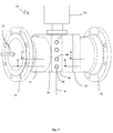
- Fig.1 1
- eine perspektivische Ansicht eines erfindungsgemäßen Ultraschalldurchflussmessgeräts;
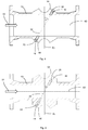
- Fig. 2 und 3
- Querschnitte entlang der Linien II-II und III-III aus
Fig. 1 ; - Fig. 4
- eine Ansicht des Ultraschalldurchflussmessgeräts in Längsrichtung;
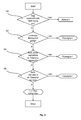
- Fig. 5
- ein Flussdiagramm des erfindungsgemäßen Verfahrens.
- Fig.1 1
- a perspective view of an ultrasonic flowmeter according to the invention;
- FIGS. 2 and 3
- Cross sections along the lines II-II and III-III
Fig. 1 ; - Fig. 4
- a view of the ultrasonic flowmeter in the longitudinal direction;
- Fig. 5
- a flow chart of the method according to the invention.
Eine erfindungsgemäße Vorrichtung 10 weist einen Messaufnehmer 12 auf, der aus einem zwischen Anschlussflanschen 14 und 16 angeordnetem Rohrleitungsabschnitt 13 besteht. Das Rohrleitungsabschnitt 13 ist in seinem Inneren vorzugsweise kreisrund mit einer Nennweite D ausgebildet, entsprechend einer an die Anschlussflansche 14 und 16 anzuschließenden, nicht näher dargestellten Rohrleitung für ein Gas. Des Weiteren weist die Vorrichtung 10 in einer Rohrwandung 18 jeweils paarweise gegenüberliegend angeordnete Ultraschallwandler 20, 22, 24, 26 auf, von denen in der Zeichnung (
Die Sonden 20, 22, 24, 26 sind gehalten in Sondenaufnahmen 40, 42, 44, 46 (
Jeweils gegenüberliegende Sondenaufnahmen 40-42, 44-46 fluchten miteinander, so dass die in die Sondenaufnahmen eingesetzten Sonden 20, 22, 24, 26 zueinander ausgerichtet sind und die Messpfade 30, 32, 34, 36 definieren (
Der durch das Innere des Messaufnehmers 12 strömende Gasdurchfluss wird in bekannter Weise bestimmt, indem zunächst die Strömungsgeschwindigkeit des Gases bestimmt wird, indem eine Laufzeitdifferenz von Ultraschallsignalen, die auf einem Messpfad in beide Richtungen laufen und damit eine Komponente in und entgegen der Strömungsrichtung besitzen, gemessen wird. Aus der Strömungsgeschwindigkeit kann mit Kenntnis des Rohrquerschnitts der Durchfluss ausgerechnet werden. Die Ultraschallwandler dienen dabei sowohl als Sender wie auch als Empfänger, so dass jeder Messpfad von den Ultraschallsignalen in beiden Richtungen genutzt wird.The gas flow flowing through the interior of the measuring
Aus der Laufzeit der Ultraschallsignale auf einem Messpfad kann die Schallgeschwindigkeit SoS (Speed Of Sound) im Gas auf dem Messpfad berechnet werden. Die Schallgeschwindigkeit SoS ist nämlich der Mittelwert der Geschwindigkeiten zweier in entgegengesetzter Richtung laufender Ultraschallsignale, also der zweifache Abtand zwischen den beiden Ultraschallwandlern dividiert durch die Summe der beiden Laufzeiten hin und zurück.From the transit time of the ultrasonic signals on a measuring path, the speed of sound SoS (Speed Of Sound) in the gas can be calculated on the measuring path. The speed of sound SoS is namely the mean of the Speeds of two ultrasound signals running in the opposite direction, ie twice the distance between the two ultrasound transducers divided by the sum of the two transit times back and forth.
Im Idealfall einer ungestörten, homogenen, laminaren oder turbulenten Strömung würde ein Messpfad ausreichen, um die Strömungsgeschwindigkeit und damit den Durchfluss zu bestimmen. Damit Inhomogenitäten im Strömungsprofil über den Querschnitt nicht das Ergebnis verfälschen, sind mehrere Messpfade vorgesehen, die das Strömungsprofil an unterschiedlichen Stellen, also mit unterschiedlichem Abstand zur Messaufnehmerachse 60 abtasten. Aus den Einzelergebnissen für die Messpfade 30, 32, 34, 36 ergibt sich durch geeignete Integrationsverfahren der Durchfluss. Die Messpfade 30, 32, 34, 36 sind so in parallelen, horizontalen Ebenen Eu1, Eu2, Eo1, Eo2 übereinander angeordnet.In the ideal case of an undisturbed, homogeneous, laminar or turbulent flow, a measuring path would be sufficient to determine the flow velocity and thus the flow. In order to prevent inhomogeneities in the flow profile over the cross section from falsifying the result, a plurality of measuring paths are provided which scan the flow profile at different locations, that is, at different distances from the
Die Erfindung fordert jetzt eine weitere spezielle Anordnung der Messpfade. Zwei Messpfade gleicher Länger bilden immer ein Paar von Messpfaden. In dem Ausführungsbeispiel nach der Zeichnung bilden die Messpfade 30 und 36 sowie 32 und 34 je ein Paar. In einem Paar haben die beiden Messpfade gleiche Länge, verlaufen parallel zueinander und erstrecken sich in separaten horizontalen Ebenen Eu1 und Eo1 bzw. Eu2 und Eo2.The invention now requires a further special arrangement of the measuring paths. Two measuring paths of equal length always form a pair of measuring paths. In the embodiment according to the drawing, the measuring
Jede horizontale Ebene eines Paares ist in vertikaler Richtung um eine gleiche, vordefinierte Distanz d1 bzw. d2 bezüglich der Mittelachse 60 verschoben, so dass eine der Ebenen Eo1 bzw. Eo2 in einem oberen Bereich oberhalb der Mittelachse 60 gelegen ist und die andere Ebene Eu1 bzw. Eu2 in einem unteren Bereich unterhalb der Mittelachse 60 gelegen ist.Each horizontal plane of a pair is displaced in the vertical direction by a same, predefined distance d1 or d2 with respect to the
Das erfindungsgemäße Verfahren betrifft jetzt die Erkennung von Flüssigkeit 50 in dem Rohrabschnitt 13. Dazu werden lediglich die sowieso für die Durchflussbestimmung vorhandenen Messungen herangezogen. Das Verfahren läuft wie nachfolgend beschrieben und wie in
Nach dem Start wird zunächst in Schritt 100 geprüft, ob überhaupt eine ausreichende Gasströmung vorliegt, denn wenn die Strömungsgeschwindigkeit des Gases nicht einen Mindestwert überschreitet, also gar keine oder eine zu langsame Strömung vorliegt, wird das Verfahren keinen Sinn machen. Dann ist es auch nicht wichtig, ob eine Flüssigkeit 50 vorliegt. Dieser Mindestwert kann theoretisch auf irgendeinem der Messpfade ermittelt werden. Vorzugsweise sollte der Mindestwert auf der obersten Ebene ermittelt werden, denn dort ist das Vorhandensein von Flüssigkeit am unwahrscheinlichsten. Es sollte jedenfalls nicht der unterste Messpfad genommen werden, denn dort ist die Wahrscheinlichkeit von Flüssigkeit am höchsten.After the start, it is first checked in
In einem folgenden Schritt 102 (erste Stufe) wird geprüft, ob der unterste Messpfad 30 einen gültigen Messwert für die Strömungsgeschwindigkeit des Gases liefert. Liegt nämlich derart viel Flüssigkeit 50 in dem Rohrabschnitt 13 vor, dass der Flüssigkeitsspiegel sich oberhalb der untersten Ebene Eu1 befindet, dann liegt der komplette Messpfad in der Flüssigkeit. Es würde dann für die Schallgeschwindigkeit SoS ein für Gas unsinniger und damit ungültiger Wert gemessen und die Messung einer Strömungsgeschwindigkeit ungültig machen. Wurde das Vorhandensein von Flüssigkeit in diesem Schritt 102 ermittelt, wird ein Flüssigkeitswarnsignal ausgegeben. Die nachfolgenden Schritte sind dann nicht mehr notwendig.In a following step 102 (first stage), it is checked whether the
In einem Schritt 104 (zweite Stufe) wird ein Turbulenzwert für jeden der beiden Messpfade eines Paares aus einer Mehrfachmessung der Strömungsgeschwindigkeiten auf einem Messpfad in einer Richtung ermittelt und das Verhältnis der beiden Turbulenzwerte gebildet. Der Turbulenzwert kann z. B. durch die Standardabweichung über mehrere Messungen der Strömungsgeschwindigkeit auf einem Messpfad in eine Richtung definiert sein. Ist die Strömung nämlich stark turbulent, wird die Strömungsgeschwindigkeit stärker streuen als in einer nicht so turbulenten Strömung. Es wird dann geprüft, ob das Verhältnis der Turbulenzwerte um mehr als einen vorgegebenen Toleranzwert von 1 abweicht. Ohne Flüssigkeit 50 im Rohrabschnitt 13 sollte das Verhältnis 1 sein oder zumindest sehr nahe an 1 liegen. Weicht das Verhältnis aber beispielsweise um mehr als 10% ab, kann das das Vorhandensein von Flüssigkeit anzeigen. Wie groß die Toleranzwerte sein sollten, muss empirisch ermittelt werden. Die Toleranzwerte können nach oben und unten auch unterschiedlich sein. Beispielsweise könnten diese so liegen, dass das Verhältnis zwischen 0,9 und 1,15 liegen sollte. Wurde das Vorhandensein von Flüssigkeit in diesem Schritt 104 ermittelt, wird ein Flüssigkeitswarnsignal ausgegeben. Der nachfolgende Schritt ist dann nicht mehr notwendig.In a step 104 (second stage), a turbulence value is determined for each of the two measurement paths of a pair from a multiple measurement of the flow velocities on a measurement path in one direction and the ratio of the two turbulence values is formed. The turbulence value can be z. B. be defined by the standard deviation over several measurements of the flow velocity on a measurement path in one direction. If the flow is highly turbulent, the flow velocity will be more scattered than in a less turbulent flow. It is then checked whether the ratio of the turbulence values deviates by more than a predetermined tolerance value of 1. Without
In einem Schritt 106 (dritte Stufe) schließlich wird die jeweilige Schallgeschwindigkeit SoS auf beiden Messpfaden eines Paares ermittelt und das Verhältnis der beiden Schallgeschwindigkeiten gebildet. Es wird dann analog wie bei den Turbulenzwerten geprüft, ob das Verhältnis der Schallgeschwindigkeiten um mehr als einen vorgegebenen Toleranzwert von 1 abweicht. Als Beispiel seien wieder Zahlen genannt. Grenzen für das Verhältnis könnten beispielsweise liegen bei 0,999 und 1,001.Finally, in a step 106 (third stage), the respective speed of sound SoS is determined on both measuring paths of a pair and the ratio of the two speeds of sound is formed. It is then tested analogously as in the turbulence values, whether the ratio of the sound velocities differs by more than a predetermined tolerance value of 1. As an example again numbers are called. Limits to the ratio could be, for example, 0.999 and 1.001.
Während des Betriebes des Ultraschalldurchflussmessgeräts wird das erfindungsgemäße Verfahren vorzugsweise permanent durchgeführt und die drei Stufen zyklisch nacheinander abgearbeitet.During operation of the ultrasonic flowmeter, the method according to the invention is preferably carried out permanently and the three stages are processed cyclically one after the other.
Claims (11)
Applications Claiming Priority (1)
| Application Number | Priority Date | Filing Date | Title |
|---|---|---|---|
| DE102015105685.2A DE102015105685B3 (en) | 2015-04-14 | 2015-04-14 | Method and apparatus for detecting the presence of liquid in a gas stream |
Publications (2)
| Publication Number | Publication Date |
|---|---|
| EP3081908A1 true EP3081908A1 (en) | 2016-10-19 |
| EP3081908B1 EP3081908B1 (en) | 2017-09-20 |
Family
ID=55312522
Family Applications (1)
| Application Number | Title | Priority Date | Filing Date |
|---|---|---|---|
| EP16159770.3A Active EP3081908B1 (en) | 2015-04-14 | 2016-03-11 | Method and device for detecting the presence of a liquid in a gas flow |
Country Status (6)
| Country | Link |
|---|---|
| US (1) | US10082486B2 (en) |
| EP (1) | EP3081908B1 (en) |
| CN (1) | CN106052780B (en) |
| DE (1) | DE102015105685B3 (en) |
| NO (1) | NO2744977T3 (en) |
| RU (1) | RU2616760C1 (en) |
Families Citing this family (8)
| Publication number | Priority date | Publication date | Assignee | Title |
|---|---|---|---|---|
| US20170212082A1 (en) * | 2016-01-21 | 2017-07-27 | Introtek International | Ultrasonic fittings |
| CN107478716B (en) * | 2017-07-06 | 2020-07-28 | 中国船舶重工集团公司第七一九研究所 | Detection device and detection method for gas-liquid two-phase distribution field in boiler |
| CH714430B1 (en) * | 2017-12-14 | 2021-10-15 | Stebatec Ag | Ultrasonic flow measuring device with flow-optimized measuring tube. |
| DK3715688T3 (en) * | 2019-03-27 | 2021-07-05 | Siemens Schweiz Ag | Integrated valve |
| ES2878335T3 (en) * | 2019-06-25 | 2021-11-18 | Sick Engineering Gmbh | Ultrasonic flowmeter |
| CN211452465U (en) * | 2019-09-30 | 2020-09-08 | 霍尼韦尔(天津)有限公司 | Ultrasonic flowmeter and fluid pipeline |
| CN111121927B (en) * | 2019-12-16 | 2022-07-15 | 金卡智能集团股份有限公司 | Water inlet detection method of electronic gas meter |
| CN112729488A (en) * | 2020-12-30 | 2021-04-30 | 浙江威星智能仪表股份有限公司 | Water inlet detection method for ultrasonic gas meter |
Citations (3)
| Publication number | Priority date | Publication date | Assignee | Title |
|---|---|---|---|---|
| EP1186868A2 (en) * | 2000-09-11 | 2002-03-13 | Daniel Industries, Inc., | Technique for measurement of gas liquid flow velocities, and liquid level in a pipe with stratified flow |
| US20100010756A1 (en) * | 2008-07-08 | 2010-01-14 | Daniel Measurement And Control, Inc. | Method and System of Detecting Liquid in an Acoustic Flow Meter |
| EP2428776B1 (en) | 2010-09-09 | 2013-08-14 | SICK Engineering GmbH | A method and apparatus for measuring a gas flow velocity |
Family Cites Families (9)
| Publication number | Priority date | Publication date | Assignee | Title |
|---|---|---|---|---|
| DE19717940C2 (en) * | 1997-04-29 | 1999-04-15 | Krohne Ag | Ultrasonic flow measurement method |
| US6732595B2 (en) * | 2002-07-18 | 2004-05-11 | Panametrics, Inc. | Method of and system for determining the mass flow rate of a fluid flowing in a conduit |
| DE102005045485A1 (en) * | 2005-09-22 | 2007-04-12 | Endress + Hauser Flowtec Ag | Method for system and / or process monitoring in an ultrasonic flowmeter |
| DE102007004936B4 (en) * | 2006-12-19 | 2011-01-13 | Krohne Ag | ultrasonic flowmeter |
| US8170812B2 (en) | 2007-10-16 | 2012-05-01 | Daniel Measurement And Control, Inc. | Method and system for detecting deposit buildup within an ultrasonic flow meter |
| EP2386835B1 (en) * | 2010-05-12 | 2015-11-25 | SICK Engineering GmbH | Ultrasound measurement of the flow speed of a fluid in a tubular conduit |
| DE102010040396A1 (en) * | 2010-09-08 | 2012-03-08 | Robert Bosch Gmbh | Flow meter for detecting a property of a fluid medium |
| WO2013177626A1 (en) * | 2012-05-30 | 2013-12-05 | Rubicon Research Pty Ltd | Silt control in fluid networks |
| US9581479B2 (en) * | 2013-04-08 | 2017-02-28 | Western Energy Support And Technology, Inc. | Ultrasonic meter flow measurement monitoring system |
-
2012
- 2012-06-19 NO NO12823708A patent/NO2744977T3/no unknown
-
2015
- 2015-04-14 DE DE102015105685.2A patent/DE102015105685B3/en not_active Expired - Fee Related
-
2016
- 2016-03-11 EP EP16159770.3A patent/EP3081908B1/en active Active
- 2016-04-06 US US15/091,893 patent/US10082486B2/en active Active
- 2016-04-12 RU RU2016113799A patent/RU2616760C1/en active
- 2016-04-14 CN CN201610235847.7A patent/CN106052780B/en active Active
Patent Citations (3)
| Publication number | Priority date | Publication date | Assignee | Title |
|---|---|---|---|---|
| EP1186868A2 (en) * | 2000-09-11 | 2002-03-13 | Daniel Industries, Inc., | Technique for measurement of gas liquid flow velocities, and liquid level in a pipe with stratified flow |
| US20100010756A1 (en) * | 2008-07-08 | 2010-01-14 | Daniel Measurement And Control, Inc. | Method and System of Detecting Liquid in an Acoustic Flow Meter |
| EP2428776B1 (en) | 2010-09-09 | 2013-08-14 | SICK Engineering GmbH | A method and apparatus for measuring a gas flow velocity |
Also Published As
| Publication number | Publication date |
|---|---|
| US10082486B2 (en) | 2018-09-25 |
| US20160305911A1 (en) | 2016-10-20 |
| NO2744977T3 (en) | 2018-07-21 |
| DE102015105685B3 (en) | 2016-03-03 |
| EP3081908B1 (en) | 2017-09-20 |
| CN106052780B (en) | 2019-01-29 |
| RU2616760C1 (en) | 2017-04-18 |
| CN106052780A (en) | 2016-10-26 |
Similar Documents
| Publication | Publication Date | Title |
|---|---|---|
| EP3081908B1 (en) | Method and device for detecting the presence of a liquid in a gas flow | |
| EP3489634A1 (en) | Ultrasonic measuring device and method for the ultrasonic measurement of a flowing fluid | |
| EP0046965A1 (en) | Method and device for determining mass flow dynamically and independent of fluid density | |
| DE10254053B4 (en) | Method and device for determining and / or monitoring a volume and / or mass flow | |
| DE102014115203B3 (en) | Method and arrangement for ultrasonic clamp-on flow measurement and circuit arrangement for controlling an ultrasonic clamp-on flow measurement | |
| EP3388794B2 (en) | Measuring device for measuring a flow speed of a fluid | |
| EP2072972B1 (en) | Device for measuring the movement of a fluid in a pipe | |
| EP1554548B1 (en) | Ultrasonic measurement of the running time and quantity for detecting the concentration of particles in a flowing fluid | |
| DE112013005279T5 (en) | Ultrasonic signal coupler | |
| DE102016116072B4 (en) | Method for detecting foreign bodies in a magneto-inductive flowmeter, a magneto-inductive flowmeter, an arrangement with a magneto-inductive flowmeter and a filling system with an arrangement | |
| DE102015111642A1 (en) | Flowmeter according to the vortex meter principle | |
| WO2018015218A1 (en) | Method and assembly for ultrasonic clamp-on flow measurement, and bodies for implementing the measurement | |
| DE102008055032B4 (en) | Arrangement and method for multiphase flow measurement | |
| DE102007053105B4 (en) | Method and device for volume flow measurement of fluids in pipelines | |
| EP3066479A1 (en) | Method and device for determining the velocity of a medium | |
| DE102017005207A1 (en) | Method for determining the pressure of a fluid | |
| WO2023227652A1 (en) | Ultrasonic through-flow measurement device for determining a through-flow of a fluidic medium through a pipeline | |
| EP3748308A1 (en) | Ultrasound flow measuring device, blocking device and use in a blocking device | |
| DE112011102854T5 (en) | Method and apparatus for calibrating a flowmeter | |
| EP3715797B1 (en) | Ultrasonic flow meter, method for operating an ultrasonic flow meter, measuring assembly and method for operating a measuring assembly | |
| EP3748309B1 (en) | Ultrasound flow measuring device, blocking device and use in a blocking device | |
| DE102009035983A1 (en) | Method and device for determining a flow rate of a fluid | |
| DE102013008437B4 (en) | Method and device for detecting flowing particles | |
| EP3642570B1 (en) | Device and methods for ultrasonic flow metering | |
| DE102016119468A1 (en) | Measurement of the density of a fluid |
Legal Events
| Date | Code | Title | Description |
|---|---|---|---|
| PUAI | Public reference made under article 153(3) epc to a published international application that has entered the european phase |
Free format text: ORIGINAL CODE: 0009012 |
|
| AK | Designated contracting states |
Kind code of ref document: A1 Designated state(s): AL AT BE BG CH CY CZ DE DK EE ES FI FR GB GR HR HU IE IS IT LI LT LU LV MC MK MT NL NO PL PT RO RS SE SI SK SM TR |
|
| AX | Request for extension of the european patent |
Extension state: BA ME |
|
| 17P | Request for examination filed |
Effective date: 20170119 |
|
| RBV | Designated contracting states (corrected) |
Designated state(s): AL AT BE BG CH CY CZ DE DK EE ES FI FR GB GR HR HU IE IS IT LI LT LU LV MC MK MT NL NO PL PT RO RS SE SI SK SM TR |
|
| 17Q | First examination report despatched |
Effective date: 20170222 |
|
| GRAP | Despatch of communication of intention to grant a patent |
Free format text: ORIGINAL CODE: EPIDOSNIGR1 |
|
| RIC1 | Information provided on ipc code assigned before grant |
Ipc: G01F 1/00 20060101ALI20170518BHEP Ipc: G01N 29/024 20060101ALI20170518BHEP Ipc: G01F 1/74 20060101ALN20170518BHEP Ipc: G01F 1/66 20060101AFI20170518BHEP |
|
| RIC1 | Information provided on ipc code assigned before grant |
Ipc: G01F 1/00 20060101ALI20170523BHEP Ipc: G01F 1/66 20060101AFI20170523BHEP Ipc: G01F 1/74 20060101ALN20170523BHEP Ipc: G01N 29/024 20060101ALI20170523BHEP |
|
| INTG | Intention to grant announced |
Effective date: 20170614 |
|
| GRAS | Grant fee paid |
Free format text: ORIGINAL CODE: EPIDOSNIGR3 |
|
| GRAA | (expected) grant |
Free format text: ORIGINAL CODE: 0009210 |
|
| AK | Designated contracting states |
Kind code of ref document: B1 Designated state(s): AL AT BE BG CH CY CZ DE DK EE ES FI FR GB GR HR HU IE IS IT LI LT LU LV MC MK MT NL NO PL PT RO RS SE SI SK SM TR |
|
| REG | Reference to a national code |
Ref country code: GB Ref legal event code: FG4D Free format text: NOT ENGLISH |
|
| REG | Reference to a national code |
Ref country code: CH Ref legal event code: EP |
|
| REG | Reference to a national code |
Ref country code: AT Ref legal event code: REF Ref document number: 930530 Country of ref document: AT Kind code of ref document: T Effective date: 20171015 |
|
| REG | Reference to a national code |
Ref country code: IE Ref legal event code: FG4D Free format text: LANGUAGE OF EP DOCUMENT: GERMAN |
|
| REG | Reference to a national code |
Ref country code: DE Ref legal event code: R096 Ref document number: 502016000147 Country of ref document: DE |
|
| REG | Reference to a national code |
Ref country code: NO Ref legal event code: T2 Effective date: 20170920 |
|
| REG | Reference to a national code |
Ref country code: NL Ref legal event code: MP Effective date: 20170920 |
|
| PG25 | Lapsed in a contracting state [announced via postgrant information from national office to epo] |
Ref country code: FI Free format text: LAPSE BECAUSE OF FAILURE TO SUBMIT A TRANSLATION OF THE DESCRIPTION OR TO PAY THE FEE WITHIN THE PRESCRIBED TIME-LIMIT Effective date: 20170920 Ref country code: SE Free format text: LAPSE BECAUSE OF FAILURE TO SUBMIT A TRANSLATION OF THE DESCRIPTION OR TO PAY THE FEE WITHIN THE PRESCRIBED TIME-LIMIT Effective date: 20170920 Ref country code: HR Free format text: LAPSE BECAUSE OF FAILURE TO SUBMIT A TRANSLATION OF THE DESCRIPTION OR TO PAY THE FEE WITHIN THE PRESCRIBED TIME-LIMIT Effective date: 20170920 Ref country code: LT Free format text: LAPSE BECAUSE OF FAILURE TO SUBMIT A TRANSLATION OF THE DESCRIPTION OR TO PAY THE FEE WITHIN THE PRESCRIBED TIME-LIMIT Effective date: 20170920 |
|
| REG | Reference to a national code |
Ref country code: LT Ref legal event code: MG4D |
|
| PG25 | Lapsed in a contracting state [announced via postgrant information from national office to epo] |
Ref country code: GR Free format text: LAPSE BECAUSE OF FAILURE TO SUBMIT A TRANSLATION OF THE DESCRIPTION OR TO PAY THE FEE WITHIN THE PRESCRIBED TIME-LIMIT Effective date: 20171221 Ref country code: RS Free format text: LAPSE BECAUSE OF FAILURE TO SUBMIT A TRANSLATION OF THE DESCRIPTION OR TO PAY THE FEE WITHIN THE PRESCRIBED TIME-LIMIT Effective date: 20170920 Ref country code: BG Free format text: LAPSE BECAUSE OF FAILURE TO SUBMIT A TRANSLATION OF THE DESCRIPTION OR TO PAY THE FEE WITHIN THE PRESCRIBED TIME-LIMIT Effective date: 20171220 Ref country code: LV Free format text: LAPSE BECAUSE OF FAILURE TO SUBMIT A TRANSLATION OF THE DESCRIPTION OR TO PAY THE FEE WITHIN THE PRESCRIBED TIME-LIMIT Effective date: 20170920 |
|
| PG25 | Lapsed in a contracting state [announced via postgrant information from national office to epo] |
Ref country code: NL Free format text: LAPSE BECAUSE OF FAILURE TO SUBMIT A TRANSLATION OF THE DESCRIPTION OR TO PAY THE FEE WITHIN THE PRESCRIBED TIME-LIMIT Effective date: 20170920 |
|
| PG25 | Lapsed in a contracting state [announced via postgrant information from national office to epo] |
Ref country code: CZ Free format text: LAPSE BECAUSE OF FAILURE TO SUBMIT A TRANSLATION OF THE DESCRIPTION OR TO PAY THE FEE WITHIN THE PRESCRIBED TIME-LIMIT Effective date: 20170920 Ref country code: ES Free format text: LAPSE BECAUSE OF FAILURE TO SUBMIT A TRANSLATION OF THE DESCRIPTION OR TO PAY THE FEE WITHIN THE PRESCRIBED TIME-LIMIT Effective date: 20170920 Ref country code: PL Free format text: LAPSE BECAUSE OF FAILURE TO SUBMIT A TRANSLATION OF THE DESCRIPTION OR TO PAY THE FEE WITHIN THE PRESCRIBED TIME-LIMIT Effective date: 20170920 |
|
| PG25 | Lapsed in a contracting state [announced via postgrant information from national office to epo] |
Ref country code: IS Free format text: LAPSE BECAUSE OF FAILURE TO SUBMIT A TRANSLATION OF THE DESCRIPTION OR TO PAY THE FEE WITHIN THE PRESCRIBED TIME-LIMIT Effective date: 20180120 Ref country code: SM Free format text: LAPSE BECAUSE OF FAILURE TO SUBMIT A TRANSLATION OF THE DESCRIPTION OR TO PAY THE FEE WITHIN THE PRESCRIBED TIME-LIMIT Effective date: 20170920 Ref country code: SK Free format text: LAPSE BECAUSE OF FAILURE TO SUBMIT A TRANSLATION OF THE DESCRIPTION OR TO PAY THE FEE WITHIN THE PRESCRIBED TIME-LIMIT Effective date: 20170920 Ref country code: EE Free format text: LAPSE BECAUSE OF FAILURE TO SUBMIT A TRANSLATION OF THE DESCRIPTION OR TO PAY THE FEE WITHIN THE PRESCRIBED TIME-LIMIT Effective date: 20170920 |
|
| REG | Reference to a national code |
Ref country code: DE Ref legal event code: R097 Ref document number: 502016000147 Country of ref document: DE |
|
| PLBE | No opposition filed within time limit |
Free format text: ORIGINAL CODE: 0009261 |
|
| STAA | Information on the status of an ep patent application or granted ep patent |
Free format text: STATUS: NO OPPOSITION FILED WITHIN TIME LIMIT |
|
| PG25 | Lapsed in a contracting state [announced via postgrant information from national office to epo] |
Ref country code: DK Free format text: LAPSE BECAUSE OF FAILURE TO SUBMIT A TRANSLATION OF THE DESCRIPTION OR TO PAY THE FEE WITHIN THE PRESCRIBED TIME-LIMIT Effective date: 20170920 |
|
| 26N | No opposition filed |
Effective date: 20180621 |
|
| PG25 | Lapsed in a contracting state [announced via postgrant information from national office to epo] |
Ref country code: MT Free format text: LAPSE BECAUSE OF FAILURE TO SUBMIT A TRANSLATION OF THE DESCRIPTION OR TO PAY THE FEE WITHIN THE PRESCRIBED TIME-LIMIT Effective date: 20170920 |
|
| PG25 | Lapsed in a contracting state [announced via postgrant information from national office to epo] |
Ref country code: SI Free format text: LAPSE BECAUSE OF FAILURE TO SUBMIT A TRANSLATION OF THE DESCRIPTION OR TO PAY THE FEE WITHIN THE PRESCRIBED TIME-LIMIT Effective date: 20170920 Ref country code: MC Free format text: LAPSE BECAUSE OF FAILURE TO SUBMIT A TRANSLATION OF THE DESCRIPTION OR TO PAY THE FEE WITHIN THE PRESCRIBED TIME-LIMIT Effective date: 20170920 |
|
| REG | Reference to a national code |
Ref country code: BE Ref legal event code: MM Effective date: 20180331 |
|
| REG | Reference to a national code |
Ref country code: IE Ref legal event code: MM4A |
|
| PG25 | Lapsed in a contracting state [announced via postgrant information from national office to epo] |
Ref country code: LU Free format text: LAPSE BECAUSE OF NON-PAYMENT OF DUE FEES Effective date: 20180311 |
|
| PG25 | Lapsed in a contracting state [announced via postgrant information from national office to epo] |
Ref country code: IE Free format text: LAPSE BECAUSE OF NON-PAYMENT OF DUE FEES Effective date: 20180311 |
|
| PG25 | Lapsed in a contracting state [announced via postgrant information from national office to epo] |
Ref country code: BE Free format text: LAPSE BECAUSE OF NON-PAYMENT OF DUE FEES Effective date: 20180331 |
|
| PG25 | Lapsed in a contracting state [announced via postgrant information from national office to epo] |
Ref country code: FR Free format text: LAPSE BECAUSE OF NON-PAYMENT OF DUE FEES Effective date: 20180331 |
|
| REG | Reference to a national code |
Ref country code: CH Ref legal event code: PL |
|
| PG25 | Lapsed in a contracting state [announced via postgrant information from national office to epo] |
Ref country code: CH Free format text: LAPSE BECAUSE OF NON-PAYMENT OF DUE FEES Effective date: 20190331 Ref country code: LI Free format text: LAPSE BECAUSE OF NON-PAYMENT OF DUE FEES Effective date: 20190331 |
|
| PG25 | Lapsed in a contracting state [announced via postgrant information from national office to epo] |
Ref country code: TR Free format text: LAPSE BECAUSE OF FAILURE TO SUBMIT A TRANSLATION OF THE DESCRIPTION OR TO PAY THE FEE WITHIN THE PRESCRIBED TIME-LIMIT Effective date: 20170920 |
|
| PG25 | Lapsed in a contracting state [announced via postgrant information from national office to epo] |
Ref country code: PT Free format text: LAPSE BECAUSE OF FAILURE TO SUBMIT A TRANSLATION OF THE DESCRIPTION OR TO PAY THE FEE WITHIN THE PRESCRIBED TIME-LIMIT Effective date: 20170920 |
|
| PG25 | Lapsed in a contracting state [announced via postgrant information from national office to epo] |
Ref country code: MK Free format text: LAPSE BECAUSE OF NON-PAYMENT OF DUE FEES Effective date: 20170920 Ref country code: RO Free format text: LAPSE BECAUSE OF FAILURE TO SUBMIT A TRANSLATION OF THE DESCRIPTION OR TO PAY THE FEE WITHIN THE PRESCRIBED TIME-LIMIT Effective date: 20170920 Ref country code: HU Free format text: LAPSE BECAUSE OF FAILURE TO SUBMIT A TRANSLATION OF THE DESCRIPTION OR TO PAY THE FEE WITHIN THE PRESCRIBED TIME-LIMIT; INVALID AB INITIO Effective date: 20160311 Ref country code: CY Free format text: LAPSE BECAUSE OF FAILURE TO SUBMIT A TRANSLATION OF THE DESCRIPTION OR TO PAY THE FEE WITHIN THE PRESCRIBED TIME-LIMIT Effective date: 20170920 |
|
| PG25 | Lapsed in a contracting state [announced via postgrant information from national office to epo] |
Ref country code: AL Free format text: LAPSE BECAUSE OF FAILURE TO SUBMIT A TRANSLATION OF THE DESCRIPTION OR TO PAY THE FEE WITHIN THE PRESCRIBED TIME-LIMIT Effective date: 20170920 |
|
| REG | Reference to a national code |
Ref country code: AT Ref legal event code: MM01 Ref document number: 930530 Country of ref document: AT Kind code of ref document: T Effective date: 20210311 |
|
| PG25 | Lapsed in a contracting state [announced via postgrant information from national office to epo] |
Ref country code: AT Free format text: LAPSE BECAUSE OF NON-PAYMENT OF DUE FEES Effective date: 20210311 |
|
| PGFP | Annual fee paid to national office [announced via postgrant information from national office to epo] |
Ref country code: IT Payment date: 20250331 Year of fee payment: 10 |
|
| REG | Reference to a national code |
Ref country code: DE Ref legal event code: R081 Ref document number: 502016000147 Country of ref document: DE Owner name: ENDRESS+HAUSER SICK GMBH+CO. KG, DE Free format text: FORMER OWNER: SICK ENGINEERING GMBH, 01458 OTTENDORF-OKRILLA, DE Ref country code: DE Ref legal event code: R082 Ref document number: 502016000147 Country of ref document: DE |
|
| PGFP | Annual fee paid to national office [announced via postgrant information from national office to epo] |
Ref country code: GB Payment date: 20260324 Year of fee payment: 11 |
|
| PGFP | Annual fee paid to national office [announced via postgrant information from national office to epo] |
Ref country code: NO Payment date: 20260320 Year of fee payment: 11 Ref country code: DE Payment date: 20260320 Year of fee payment: 11 |