EP3082003A1 - Procédé et dispositif d'exécution du test automatique d'une solution d'automatisation - Google Patents
Procédé et dispositif d'exécution du test automatique d'une solution d'automatisation Download PDFInfo
- Publication number
- EP3082003A1 EP3082003A1 EP15164108.1A EP15164108A EP3082003A1 EP 3082003 A1 EP3082003 A1 EP 3082003A1 EP 15164108 A EP15164108 A EP 15164108A EP 3082003 A1 EP3082003 A1 EP 3082003A1
- Authority
- EP
- European Patent Office
- Prior art keywords
- test
- automation
- test case
- transactional
- simulator
- Prior art date
- Legal status (The legal status is an assumption and is not a legal conclusion. Google has not performed a legal analysis and makes no representation as to the accuracy of the status listed.)
- Withdrawn
Links
Images


Classifications
-
- G—PHYSICS
- G05—CONTROLLING; REGULATING
- G05B—CONTROL OR REGULATING SYSTEMS IN GENERAL; FUNCTIONAL ELEMENTS OF SUCH SYSTEMS; MONITORING OR TESTING ARRANGEMENTS FOR SUCH SYSTEMS OR ELEMENTS
- G05B23/00—Testing or monitoring of control systems or parts thereof
- G05B23/02—Electric testing or monitoring
- G05B23/0205—Electric testing or monitoring by means of a monitoring system capable of detecting and responding to faults
- G05B23/0218—Electric testing or monitoring by means of a monitoring system capable of detecting and responding to faults characterised by the fault detection method dealing with either existing or incipient faults
- G05B23/0256—Electric testing or monitoring by means of a monitoring system capable of detecting and responding to faults characterised by the fault detection method dealing with either existing or incipient faults injecting test signals and analyzing monitored process response, e.g. injecting the test signal while interrupting the normal operation of the monitored system; superimposing the test signal onto a control signal during normal operation of the monitored system
-
- G—PHYSICS
- G05—CONTROLLING; REGULATING
- G05B—CONTROL OR REGULATING SYSTEMS IN GENERAL; FUNCTIONAL ELEMENTS OF SUCH SYSTEMS; MONITORING OR TESTING ARRANGEMENTS FOR SUCH SYSTEMS OR ELEMENTS
- G05B23/00—Testing or monitoring of control systems or parts thereof
- G05B23/02—Electric testing or monitoring
- G05B23/0205—Electric testing or monitoring by means of a monitoring system capable of detecting and responding to faults
- G05B23/0218—Electric testing or monitoring by means of a monitoring system capable of detecting and responding to faults characterised by the fault detection method dealing with either existing or incipient faults
- G05B23/0243—Electric testing or monitoring by means of a monitoring system capable of detecting and responding to faults characterised by the fault detection method dealing with either existing or incipient faults model based detection method, e.g. first-principles knowledge model
- G05B23/0245—Electric testing or monitoring by means of a monitoring system capable of detecting and responding to faults characterised by the fault detection method dealing with either existing or incipient faults model based detection method, e.g. first-principles knowledge model based on a qualitative model, e.g. rule based; if-then decisions
Definitions
- the invention relates to a method for the automatic testing of an automation solution loaded into an automation system as well as to a system designed for carrying out the method and designed to execute the method.
- the test refers to at least one control program of the automation solution.
- the respective process peripherals and, on the other hand, an interface for operator actions of a human operator are necessary.
- an interface for operations of an operator HMI interface, peripherals and software for so-called operator control and monitoring
- HMI interface, peripherals and software for so-called operator control and monitoring is often only available when the development of the control program is completed to a large extent. For this reason, tests of an automation solution are only possible in a relatively late development stage of the automation solution.
- An object of the invention is to provide a way by which the testing of an automation solution can begin even at a relatively early stage of development.
- the system simulator comprises a test controller or the system simulator is assigned such a function.
- the test controller controls to simulate interactions of an operator transactional HMI model determined with the automation solution.
- the transactional HMI model uses a given description of a test case. This description will be referred to below as a test case and this will be processed by means of the test controller and the transactional HMI model.
- a control program of the respective automation solution to be tested comprises instrumented function blocks.
- the instrumented function modules comprise as instrumentation means for detecting a test coverage during the execution of the test case, for example an interface that allows the test controller to query the coverage of the program code included in the function module after a test. At the end of the test, a test coverage report is automatically generated from the detected test coverage by the equipment simulator.
- the advantage of the invention is that the test can be carried out automatically and on account of the transactional HMI model already at a very early point in time, that is to say at a point in time at which system images configured for interaction with the automation solution for the so-called operating and monitoring of the automation usually not or not yet sufficiently available.
- test method proposed here By means of the test method proposed here, continuous quality assurance can be achieved during the creation (engineering) of the respective automation solution. Another possibility for cost reduction results from the fact that the test method proposed here can run automatically and unattended, for example "overnight”.
- the ability to continually test the automation solution results in significant time savings in the final automation test associated with handing over to the actual operator, thus saving time on tests called FAT (Factory Acceptance Test) or SAT (Site Acceptance Test).
- test cases used and test cases adapted or supplemented in the course of the test procedure can be used again, for example for later testing of the same automation solution, if, for example, reengineering is necessary for this, or for testing another automation solution based on the same function blocks. which is very often the case.
- a report on the achieved test coverage is automatically generated after completion of the processing of the respective test case.
- the automatic generation of a report or - in the case of a successive execution of several test cases - several reports ensures a complete documentation of the results of the test procedure.
- the report for the achieved test coverage is generated on the basis of data read from the automation system.
- data read from the automation system For example, it is provided that as instrumentation of a Function blocks as well as a means for determining a test cover a counter and an instruction to increment the counter function and that the counter is incremented at each of the statement enclosing flow of the instrumented function block.
- Such counter readings can be automatically read out by means of the system simulator or the test controller of the system simulator in a manner known per se and also processed automatically for a report for test coverage.
- the or each counter provided within the scope of instrumentation of a function block is created in a respective instance data block of the respective instrumented function block. This facilitates an assignment of the counter provided for detecting the respective code coverage of a function module to exactly one respective function module.
- an instruction for incrementing the counter is executed only during the execution of a test case.
- the value of a variable acting as a flag can be queried in the context of the instruction.
- this variable is set to a first predetermined or predefinable value and set to a different value during execution of the control program during normal operation, ie outside the test method, so that a test situation and normal operation are automatically and unambiguously distinguishable.
- a test case and in particular by means of an associated test case script, comprises and / or enables a variation of test values defined therein.
- the test can be carried out by means of a test case on the basis of a plurality of test values.
- test modules allow archiving of used test cases or test cases and associated test case scripts in a particularly simple manner.
- test modules allow a later re-implementation of already applied tests and / or their use for other automation solutions.
- test cases are automatically generated by means of a test case generator from existing data sources, in particular so-called audit trails.
- the automatic generation of test cases leads to a significantly reduced effort in connection with the testing of an automation solution.
- the automatic generation of test cases based on, for example, audit trails allows the use of real values as test values and thus the use of plausible and realistic test values.
- the plant simulator, the test controller and the transactional HMI model are implemented in software, so that the invention is also a computer program comprising the functionality of the plant simulator, the test controller and the transactional HMI model, possibly in the form of a distributed computer program namely, a computer program with program code means for carrying out all the steps of the method described here and possibly the method in the form of individual embodiments or in the form of a combination of several embodiments, when the computer program is loaded on a self-machine simulator for automatic testing of a computer loaded into an automation system Automation solution is executed.
- the invention is also a system with an automation system and a communicatively associated system simulator, wherein in a memory of the automation system as an automation solution, a control program is loaded, the system simulator using at least one predetermined test case and using a plant model, a test controller and a transactional HMI model designed to emulate interactions of an operator with the automation solution executes the test case, wherein the control program comprises instrumented function modules, wherein means for detecting a test coverage during the processing of the test case act as instrumentation and wherein by means of the system simulator and the test controller resulting test coverage can be determined.
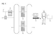
- FIG. 1 shows in schematically simplified form an arrangement for testing control programs.
- An automation system 10 in whose memory the control program to be tested or at least one control program to be tested is loaded, is communicatively connected via a field bus 12 to other automation systems 10 and the like.
- a fieldbus 12 is communicatively connected to the automation system 10.
- the automation system 10 and the simulation interface 14 can be reached via a system bus 16, for example an Industrial Ethernet bus, for other communication users, namely a system simulator 18 and a server 20.
- a device 22 acting as a client, for example a programming device or the like, is over a local bus 24 communicatively connected to the plant simulator 18 and the server 20.
- a tester for testing the automation system 10 and the at least one control program can execute test cases 26 with respect to the automation system 10 and its control program (s).
- Such a test is referred to below as testing an automation solution or in short as testing the automation, since the automation system 10 and the at least one control program running on it are provided for automation of a technical process, not shown here.
- test coverage is usually only small, since the number of available test cases 26 and the time frame for their application are limited.
- test coverage is usually only small, since the number of available test cases 26 and the time frame for their application are limited.
- test coverage is often only partially reproducible, since they are dependent on the reactivity of the tester and / or the respective initial states of the automation system 10, for example.
- FAT Factory Acceptance Test
- SAT Site Acceptance Test
- the test is only carried out at a very late stage in engineering. For example, plant images or the like for the operator control and monitoring must be configured for the test and provided by means of a server 20.
- a possibility for an efficient test of one or more control programs is often only given when also large parts of the control system are completed.
- a comprehensive test in early project phases is only possible to a limited extent.
- FIG. 2 shows in the form of a schematically simplified object model proposed here for the test of an automation solution and at least one of them included control program approach.
- the automation system 10 is shown on the left.
- at least one control program to be tested is loaded in a manner known per se.
- the automation system 10 and its control program (e) can be regarded as one and the same functional unit for the further description.
- an automation solution often comprises a plurality of control programs.
- an automation solution often comprises a plurality of control programs.
- the possibility of a plurality of control programs must always be read. This also applies accordingly to other expressions used in the singular, for example test case 26, system model 30 and so on.
- a system simulator 18 is also used for a test of an automation solution according to the approach proposed here. Again, as in the automation system 10 and its control program, an identical name for the respective hardware and running on this software used. This also applies below without corresponding Note for further functional units.
- the system simulator 18 uses the components described below or is extended by these.
- the system simulator 18 uses at least one system model 30 of processes or sub-processes of the technical process to be automated with the control program to be tested.
- the plant model 30 simulates the behavior of the technical process to be automated and / or a plant part.
- a coupling 32 AS coupling
- the system simulator 18 can interact with the automation, namely the automation system 10 and its control program. This includes an exchange of process values or the making of HMI-relevant inputs, such as setting a control value and the like.
- the plant simulator 18 is assigned a test controller 34 or the plant simulator 18 includes such a test controller 34. This controls the processing of the test cases 26 and loads a transactional HMI model 36.
- the transactional HMI model 36 serves as an abstract test interface for HMI -relevant interactions with the automation system 10.
- the test controller 34 manages all test cases 26 and controls, monitors and coordinates their execution. On the part of the automation system 10, when executing a test case 26, the control program consisting of one or more function blocks 38 is executed.
- a test case 26 is executed by the test controller 34 managing the test cases 26 and assigning a test case 26 to the transactional HMI model 36, respectively.
- the transactional HMI model 36 then processes the test case 26. If a test case 26 has been processed, it is provided in accordance with the approach proposed here that a test coverage (code coverage) of the function modules 38 instrumented for this purpose can be read out of the automation system 10 via the coupling 32 and by the test controller 34 for statistical evaluations the test controller 34 reads out corresponding data from the automation system 10 as part of the test and for its documentation. Based The data obtained thereby is generated by the test controller 34, a report. In connection with or subsequently, the next test case 26 is selected for execution, in particular automatically selected, and subsequently executed.
- a description of a test case 26 may be made by a variety of means, for example, using a formal description language such as UML (Unified Modeling Language).
- function block 38 As instrumentation for the detection of the test coverage (instrumented function blocks 38) have an interface that allows the test controller 34 to cover the cover of the test cover after a test interrogated by the function block 38 included program codes.
- instrumentation is known in software development enriching a source code with additional information, which allow an investigation of the behavior of the respective computer program.
- FIG. 3 shows by way of example the instrumentation of the program code instructions of a function module 38, here in the form of an SCL code 40, for determining the code coverage by a test case 26.
- the program code instructions here the SCL code 40
- functions in particular function calls, supplemented with their Help, for example, a counter in an associated instance data block 42 is incremented at each pass.
- the instrumentation function is implemented so that it is executed only during a test or simulation, but not during productive operation.
- the test controller 34 can determine the entire code coverage of the control program by reading out the or each affected counter, in particular by reading the instance data blocks 42, via the coupling 32 and process it for a report.
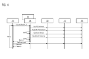
- FIG. 4 shows this process by way of example in the form of a sequence diagram.
- the projected and instrumented function modules 38 of the automation to be tested (model under test) are loaded for the test into the real or virtual automation system 10 coupled to the system simulator 18 and stimulated by the system model 30 and by the transactional HMI model 36 for the test.
- test case 26 includes, for example, the specification of a control value of a PID algorithm.
- This specification is made by means of the transactional HMI model 36 or by means of the plant model 30 and the transactional HMI model 36: "Set (PID control value)”.
- the coupling 32 the simulated operating action reaches the automation system 10 and there causes the call of the instrumented function module 38.
- a process value of the PID control is read: "Read (PID process value").
- a check can be provided, for example, whether the preset control value has been set or whether the read process value is within the range of an expected value: "Verify”.
- an operator action is simulated by means of the transactional HMI model 36, which is intended to open a valve: “Set (valve open)”. Then the resulting position of the valve is determined: “Read (valve position)”. Based on the resulting valve position, it can be determined whether the previous command to open the valve has been executed correctly: “Verify”.
- the test case 26 is finished with this: "Done ()”.
- the code coverage is determined: "GetCoverage ()”. Again after that - or at another appropriate time - a report on the determined code coverage is generated: "Generate Report ()". Again, afterwards or even independently of the generation of the report, the processing of the next test case 26 can take place: "Next ()”.
- the extension of the system simulator 18 to a transactional HMI model 36 is the automated and reproducible simulation of operator interaction with the automation, so the automation system 10 and the control program executed therewith and the plant model 30 or possibly the respective automated technical process, namely interactions , as they belong to the so-called operating and observing.
- the interactions automated by means of the transactional HMI model 36 are carried out without the use of plant images or the like, which are often not available in an early projecting phase in which a test is already possible according to the approach proposed here.
- the transactional HMI model 36 allows repeated and automated testing.
- the transactional HMI model 36 generates HMI-relevant operator inputs to stimulate automation. Examples of this are already given in connection with the explanation of the representation in FIG FIG.
- Test cases 26 may be in the form of manually programmed test scripts 44 generated from other description sources will be realized.
- the representation in FIG. 5 shows a test case script 44 to a test case 26 in the form of a UML sequence diagram.
- UML Unified Modeling Language
- UML is known to be a formal specification language, which can be mapped by appropriate generators in different implementation languages and thus also as a basis for scripts, here test case scripts 44, comes into consideration.
- the sequence diagram shows how the manipulative HMI model 36 first of all changes a manipulated variable x of a controller module in an automation system 10 to a respective instance data module 42: "Write (PID_1_stable, x)". After waiting a defined period of time (“Wait (ty)") is checked by reading back from the relevant instance data block 42, whether the control value has actually been set in the automation system 10: "Read (PID_1_Stellwert)". The value x 'is returned to the read command. If the value read back x 'does not match the previously set value x, an error message will appear in the report otherwise covering the test coverage: "Output (Error ...)".
- the test cases 26 include the stimulation of the control program from the HMI point of view, including the expected responses (functional and temporal) from the automation system 10.
- a test case script 44 belonging to a test case 26 a variation of test values defined therein is also possible, so that a flock of Parameter tupling can be used and the resulting reactions tested can be.
- expiration of a respective test case 26 it can be checked via the mentioned instrumented function modules 38 which degree of code coverage has been achieved in the respective automation function.
- test modules 38 can be reused in new instances of the function block 38. This procedure ensures a successively improved test coverage of the code.
- test modules can also be used in new instances of the function module 38 of a later other automation and are there then directly, so without additional development effort, available.
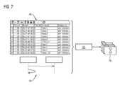
- FIG. 6 Another approach to generating test cases 26 is to include existing data sources from already configured assets.
- Today's control systems have, for example, the possibility of generating a so-called audit trail 46 (FIG. FIG. 6 ).
- audit trails are particularly important where production-relevant data is generated, changed or deleted during normal operation by user intervention.
- These operator actions are automatically logged in message archives, with all events (old value, new value, user ID, date and time stamp, operation and / or batch name etc.) recorded.
- the representation in FIG. 6 shows an exemplary extract of an audit trail 46 from a message archive.
- such an audit trail 46 or comparable data can be used to derive, for example, HMI-relevant test case scripts 44 therefrom.
- test cases 26 and test case scripts 44 can be generated automatically by means of a transactional HMI model 36 (FIG. FIG. 2 ) can be processed.
- Due to the execution of a test case 26 and / or on the basis of a generated report can be generated automatically reports that based on the result of the execution of the test cases 26 analog and dynamic signals not only a "okay” - / "not in order” Characteristics, but also include such variables as dead time, variance, mean, moving average, sample variance and the like. Due to a variance of the input parameters via corresponding test case scripts 44, such a distribution evaluation is possible.
- test setup in the form of a system, as schematically simplified in the illustration in FIG. 8 is shown.
- Significantly more profound and reproducible tests can be run.
- the engineering of a system ie the automation system 10 and the control program executed therefrom, can be checked continuously.
- a complete and automated audit is possible.
- test cases 26, test case scripts 44 and / or test modules can of course be used for other systems or in case of a later change in the tested system for the modified system (reengineering), as well as in other systems, but at least in the modified system, the respective control programs are based on similar automation functions and function blocks 38.
- a hardware component namely a computer or the like, also functions as a system simulator (18) in that the system simulator (18) executed in software is executed there.
- the plant simulator (18) comprises a test controller (34).
- the test controller (34) controls a transactional HMI model (36) to emulate interactions of an operator with the automation solution. This uses a given test case (26) and this is processed by means of the test controller (34) and the transactional HMI model (36).
- On the part of the automation system (10) comprises a control program as part of the respective automation solution instrumented function blocks (38) and the instrumented function blocks (38) have as instrumentation means for detecting a test coverage during the execution of the test case (26).
Landscapes
- Physics & Mathematics (AREA)
- General Physics & Mathematics (AREA)
- Engineering & Computer Science (AREA)
- Automation & Control Theory (AREA)
- Testing And Monitoring For Control Systems (AREA)
Priority Applications (1)
| Application Number | Priority Date | Filing Date | Title |
|---|---|---|---|
| EP15164108.1A EP3082003A1 (fr) | 2015-04-17 | 2015-04-17 | Procédé et dispositif d'exécution du test automatique d'une solution d'automatisation |
Applications Claiming Priority (1)
| Application Number | Priority Date | Filing Date | Title |
|---|---|---|---|
| EP15164108.1A EP3082003A1 (fr) | 2015-04-17 | 2015-04-17 | Procédé et dispositif d'exécution du test automatique d'une solution d'automatisation |
Publications (1)
| Publication Number | Publication Date |
|---|---|
| EP3082003A1 true EP3082003A1 (fr) | 2016-10-19 |
Family
ID=53039221
Family Applications (1)
| Application Number | Title | Priority Date | Filing Date |
|---|---|---|---|
| EP15164108.1A Withdrawn EP3082003A1 (fr) | 2015-04-17 | 2015-04-17 | Procédé et dispositif d'exécution du test automatique d'une solution d'automatisation |
Country Status (1)
| Country | Link |
|---|---|
| EP (1) | EP3082003A1 (fr) |
Cited By (1)
| Publication number | Priority date | Publication date | Assignee | Title |
|---|---|---|---|---|
| CN120631793A (zh) * | 2025-08-13 | 2025-09-12 | 北京忆恒创源科技股份有限公司 | 一种提升自动化测试有效性的测试用例调度方法、装置及存储设备 |
-
2015
- 2015-04-17 EP EP15164108.1A patent/EP3082003A1/fr not_active Withdrawn
Non-Patent Citations (2)
| Title |
|---|
| ASEM ELTAHER ET AL: "A generic architecture for hybrid intelligent test systems", CYBERNETIC INTELLIGENT SYSTEMS, 2008. CIS 2008. 7TH IEEE INTERNATIONAL CONFERENCE ON, IEEE, PISCATAWAY, NJ, USA, 9 September 2008 (2008-09-09), pages 1 - 8, XP031435971, ISBN: 978-1-4244-2914-1 * |
| STEPHAN SCHULZ ET AL: "Towards Model-Based Testing with Architecture Models", ENGINEERING OF COMPUTER-BASED SYSTEMS, 2007. ECBS '07. 14TH ANNUA L IEEE INTERNATIONAL CONFERENCE AND WORKSHOPS ON THE, IEEE, PI, 1 March 2007 (2007-03-01), pages 495 - 502, XP031073982, ISBN: 978-0-7695-2772-7 * |
Cited By (1)
| Publication number | Priority date | Publication date | Assignee | Title |
|---|---|---|---|---|
| CN120631793A (zh) * | 2025-08-13 | 2025-09-12 | 北京忆恒创源科技股份有限公司 | 一种提升自动化测试有效性的测试用例调度方法、装置及存储设备 |
Similar Documents
| Publication | Publication Date | Title |
|---|---|---|
| DE19781804B4 (de) | Vorrichtung zur Simulation einer Echtzeit-Prozesssteuerung | |
| EP2685382B1 (fr) | Procédé et dispositif de création et de test d'un programme d'appareil de commande | |
| WO1997012301A1 (fr) | Procede de conception pour systemes industriels et systemes de construction, et systeme de planification assiste par ordinateur a utiliser dans le cadre dudit procede | |
| EP3306295B1 (fr) | Procédé et dispositif d'essai de commandes électroniques, en particulier d'essai de commandes automobiles | |
| DE20321699U1 (de) | Rechner zum Durchführen eines Simulationsverfahrens für eine Bearbeitung eines Werkstücks durch eine Werkzeugmaschine | |
| WO2003027850A2 (fr) | Procede pour verifier le logiciel d'unites de commande et systeme de verification | |
| EP3379351B1 (fr) | Procédé de fonctionnement d'un dispositif d'automatisation et dispositif d'automatisation | |
| EP1906377A1 (fr) | Système et procédé d'intégration d'un système de contrôle de processus industriel dans un simulateur d'entraînement | |
| EP2897011A1 (fr) | Procédé et système de simulation pour la simulation d'une installation industrielle automatisée | |
| DE102009059865A1 (de) | Integriertes Testsystem und Verfahren zur Bewertung eines Fertigungsautomatisierungssystems | |
| EP2330469B1 (fr) | Procédé et environnement de développement destinés à produire un programme de commande complet exécutable | |
| DE102017120016A1 (de) | Verfahren zur Konfiguration eines zum Testen eines elektronischen Steuergeräts eingerichteten Testgeräts sowie Konfigurationssystem | |
| EP4314962A1 (fr) | Procédé et système de gestion d'alarmes dans des installations de production modulaires | |
| EP3082003A1 (fr) | Procédé et dispositif d'exécution du test automatique d'une solution d'automatisation | |
| WO2017029087A1 (fr) | Procédé de création automatique d'un modèle de processus et dispositif pour mettre en œuvre le procédé | |
| WO2020099524A1 (fr) | Procédé et systèmes pour fournir des données de puissance d'un appareil de commande en mode de conduite | |
| EP4123396A1 (fr) | Technique destinée à la réalisation d'une visualisation pour une installation technique d'automatisation dotée d'une commande à mémoire programmable | |
| DE10325513B4 (de) | Verfahren und Vorrichtung zum Erstellen eines Verhaltensaspekts einer Schaltung zur formalen Verifikation | |
| DE102020205980A1 (de) | Verfahren und Vorrichtung zum Simulieren eines technischen Systems | |
| DE102006060322A1 (de) | Verfahren und Vorrichtung zum automatischen Testen von modellbasierten Funktionen | |
| DE102020213809A1 (de) | Verfahren zum Betreiben eines Steuergeräts beim Testen einer Software des Steuergeräts und Verfahren zum Betreiben eines Testcomputers beim Testen einer Software eines Steuergeräts | |
| DE102011079429A1 (de) | Performancesimulation von medizintechnischen Prozeduren in einer Client-Server-Umgebung | |
| WO2025242401A1 (fr) | Procédé mis en œuvre par ordinateur pour analyser et/ou adapter le fonctionnement d'un système technique | |
| WO1999038024A1 (fr) | Procede d'optimisation de specifications de controle et de minimisation de logiciels de controle assistees par ordinateur | |
| DE102010014720A1 (de) | Verfahren zum Verifizieren eines aus einem Quellmodell generierten Zielprogramms |
Legal Events
| Date | Code | Title | Description |
|---|---|---|---|
| PUAI | Public reference made under article 153(3) epc to a published international application that has entered the european phase |
Free format text: ORIGINAL CODE: 0009012 |
|
| AK | Designated contracting states |
Kind code of ref document: A1 Designated state(s): AL AT BE BG CH CY CZ DE DK EE ES FI FR GB GR HR HU IE IS IT LI LT LU LV MC MK MT NL NO PL PT RO RS SE SI SK SM TR |
|
| AX | Request for extension of the european patent |
Extension state: BA ME |
|
| RAP1 | Party data changed (applicant data changed or rights of an application transferred) |
Owner name: SIEMENS AKTIENGESELLSCHAFT |
|
| STAA | Information on the status of an ep patent application or granted ep patent |
Free format text: STATUS: THE APPLICATION IS DEEMED TO BE WITHDRAWN |
|
| 18D | Application deemed to be withdrawn |
Effective date: 20170420 |