EP3082055A1 - Simulation de composant de giravion utilisant une géométrie à balayage - Google Patents
Simulation de composant de giravion utilisant une géométrie à balayage Download PDFInfo
- Publication number
- EP3082055A1 EP3082055A1 EP16164943.9A EP16164943A EP3082055A1 EP 3082055 A1 EP3082055 A1 EP 3082055A1 EP 16164943 A EP16164943 A EP 16164943A EP 3082055 A1 EP3082055 A1 EP 3082055A1
- Authority
- EP
- European Patent Office
- Prior art keywords
- geometry
- scan
- component
- cad
- fea
- Prior art date
- Legal status (The legal status is an assumption and is not a legal conclusion. Google has not performed a legal analysis and makes no representation as to the accuracy of the status listed.)
- Granted
Links
Images


Classifications
-
- G—PHYSICS
- G06—COMPUTING OR CALCULATING; COUNTING
- G06F—ELECTRIC DIGITAL DATA PROCESSING
- G06F30/00—Computer-aided design [CAD]
- G06F30/20—Design optimisation, verification or simulation
- G06F30/23—Design optimisation, verification or simulation using finite element methods [FEM] or finite difference methods [FDM]
-
- G—PHYSICS
- G06—COMPUTING OR CALCULATING; COUNTING
- G06F—ELECTRIC DIGITAL DATA PROCESSING
- G06F30/00—Computer-aided design [CAD]
- G06F30/10—Geometric CAD
- G06F30/17—Mechanical parametric or variational design
Definitions
- the present disclosure relates, in general, to rotorcraft component simulation based upon finite element analysis of three dimensional scan data and, in particular, to structural analysis of as-produced rotorcraft components using three dimensional scan-based finite element analysis.
- Computer-aided design is the use of computer systems to aid in the creation, modification, analysis and/or optimization of a design.
- CAD Computer-aided design
- CAD has become an important tool used for design and analysis of mechanical components and mechanical systems in many industries including automotive, shipbuilding and aerospace, to name a few.
- CAD software is used to create CAD geometry that is a digital representation of the intended physical component. Use of the CAD geometry then allows for rapid modification of the component to support the design process.
- FEA finite element analysis
- FEA provides a mathematical estimation of dependent variables such as deflections, stresses, temperatures and the like by subdividing the larger boundary value problem into simpler parts, known as finite elements, then solving a resulting system of equations.
- finite elements are typically made up of a complex system of points and grids known as nodes and elements.
- the resulting CAD geometry may be transferred to the production environment through 2D drawings or 3D solids including all details of the component in its nominal condition.
- CAD output in the form of electronic files may be used to control machining tools or other operations during the manufacturing of the actual component.
- the present disclosure is directed to a method of performing structural analysis relating to a component having CAD-based geometry, refined CAD-based geometry and CAD-based FEA data associated therewith.
- the method includes scanning the component to obtain scan-based point cloud geometry of the component; aligning the scan-based point cloud geometry with the CAD-based geometry of the component; generating scan-based geometry of the component by refining the scan-based point cloud geometry; comparing the scan-based geometry with the refined CAD-based geometry of the component to quantify geometric differences therebetween; generating scan-based FEA geometry of the component by meshing the scan-based geometry; performing finite element analysis on the scan-based FEA geometry to obtain scan-based FEA data; and comparing the scan-based FEA data with the CAD-based FEA data of the component to quantify the effect of geometric difference therebetween.
- the method may also include using a scanning system selected from the group consisting of laser scanning systems and structured light scanning systems; using at least one of fully parametric geometry, fully non-parametric geometry and hybrid geometry; comparing the scan-based geometry with the scan-based point cloud geometry and determining whether any deviations therebetween are within an acceptable level to validate the refining process, wherein the acceptable level for deviations may be deviations within a noise level of the scanning process; comparing the scan-based FEA geometry with the scan-based point cloud geometry and determining whether any deviations therebetween are within an acceptable level to validate the meshing process, wherein the acceptable level for deviations may be deviations within a noise level of the scanning process; and/or selecting the component from the group consisting of a rotorcraft component, a forged component, a cast component, a test part component, a component having a weldment, a repaired component and a damaged component.
- the present disclosure is directed to a method of qualifying a component having a defect.
- the method includes scanning the component having the defect to obtain scan-based point cloud geometry of the component having the defect; generating scan-based geometry of the component having the defect by refining the scan-based point cloud geometry; generating scan-based FEA geometry of the component having the defect by meshing the scan-based geometry; performing finite element analysis on the scan-based FEA geometry of the component having the defect; determining whether the defect is critical to the operation of the component having the defect based upon the finite element analysis; and qualifying the component having the defect if the defect is not critical to the operation of the component having the defect.
- the present disclosure is directed to a method of performing structural analysis relating to a component having CAD-based geometry, refined CAD-based geometry and CAD-based FEA data associated therewith.
- the method includes scanning the component to obtain scan-based point cloud geometry of the component; aligning the scan-based point cloud geometry with the CAD-based geometry of the component; generating scan-based geometry of the component by refining the scan-based point cloud geometry; comparing the scan-based geometry with the scan-based point cloud geometry and determining whether any deviations therebetween are within an acceptable level to validate the refining process; comparing the scan-based geometry with the refined CAD-based geometry of the component to quantify geometric differences therebetween; generating scan-based FEA geometry of the component by meshing the scan-based geometry; comparing the scan-based FEA geometry with the scan-based point cloud geometry and determining whether any deviations therebetween are within an acceptable level to validate the meshing process; performing finite element analysis on the scan-based FEA geometry to obtain scan-based FEA data
- CAD geometry is commonly used for design and analysis of mechanical components including rotorcraft components.
- This CAD-based geometry is a digital representation of the intended physical component that enables rapid modification of the component to support the design process.
- Finite element analysis (FEA) is a software tool that further enhances the design process by providing a mathematical estimation of dependent variables by subdividing the larger boundary value problem into simpler parts and solving a resulting system of equations. These finite elements are made up of a complex system of points and grids known as nodes and elements.
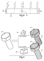
- a workflow diagram for FEA of CAD-based geometric data is generally designated 10.
- the illustrated workflow process 10 has three phases; namely, the acquisition phase 12, the refinement phase 14 and the evaluation phase 16.
- the acquisition phase 12 involves using a CAD software tool to draw the desired component, such as a rotorcraft component 18 of figure 2 .
- the CAD-based geometry of component 18 can later be used in a production environment and thus, typically includes all the geometric details of component 18 in its nominal condition. Alternatively or additionally, the CAD-based geometry could be based upon minimum and/or maximum material tolerance conditions or other desired criteria.
- the geometric refinement phase 14 of workflow process 10 includes the operations needed to prepare the CAD-based geometry for later FEA analysis. For example, this includes modifying surfaces for load application, slicing, adding/modifying mating parts or fasteners and defeaturing. Since CAD-based geometry is created to guide production processes, it may be unnecessarily complex for FEA. To simplify the CAD-based geometry, defeaturing not only removes small features and details that do not influence the areas of interest to the FEA analysis, but also aids in meshing operations and overall solution time.
- a rotorcraft component illustrated as fastener 20 has a head 22, a shaft 24 and a coupling assembly 26 used to secure fastener 20 to a mating component (not illustrated).
- coupling assembly 26 includes an opening 28 through shaft 24, a pin assembly 30 extending through opening 28 and a support assembly 32.
- the illustrated coupling assembly 26 is just one of many ways to secure fastener 20 within a mechanical system. The forces applied to shaft 24 of fastener 20 during operation, however, may not be dictated by the precise design of coupling assembly 26.
- fastener 20 could be represented as fastener 34, which is a defeatured version of fastener 20.
- fastener 34 is a defeatured version of fastener 20.
- hexagonal head 22 and its interface with shaft 24 are now represented by cylindrical head 36 having parametric surfaces.
- coupling assembly 26 is now represented by cylindrical head 38 having parametric surfaces.
- hole 42 produces a local stress concentration which influences the nearby stress distribution but farther away it has no effect. It should be noted, however, that care must be taken to avoid defeaturing geometry in a high stress location. For example, hole 42 in figure 4 should not be defeatured because it causes the highest stress in cylindrical bar 40. Accordingly, load application or boundary condition effects should also be considered in preparing CAD-based geometry for analysis. If an entire component, including attachment surfaces, is to be analyzed, then attention must be given to accurately model the load distribution into and out of the component. Realistic load application is difficult to simulate directly so mating parts are typically added to provide the proper underlying stiffness of the joint for more accurate load distribution.
- the CAD-based geometry is modified during the refinement phase 14 and may now be referred to as refined CAD-based geometry, which is ready for the evaluation phase 16 of the workflow process 10, as seen in figure 1 .
- the evaluation phase 16 determines whether the design of a component fulfills the requirements for its function, such as supporting the expected loads, while remaining within the limits of static and fatigue stresses and strains allowed for the material.
- the evaluation phase 16 may include assignment of material properties, defining part interactions, meshing, application of boundary conditions/loads, solution computation and interpretation of results. Key choices must be made at each one of these steps which will influence to varying degrees the results of the analysis.
- the most influential step, in terms of geometry, is meshing.
- Meshing is the conversion of the modified CAD-based geometry into CAD-based FEA geometry in the form of representative finite elements, as shown in figure 5 .
- a rotorcraft component 50 is meshed with tetrahedron shaped elements to form a CAD-based FEA geometry component 52 and with hexahedron shaped elements to form a CAD-based FEA geometry component 54.
- each tetrahedron 56 has four triangular sides with a node at each corner and between each corner node.
- each hexahedron element 58 includes 12 nodes between the corners and/or 8 nodes at the corners.
- FEA is an iterative process where a coarse mesh is initially generated to allow for quicker debugging of the model and identification of the critical locations. Refinement of the mesh can be done in a localized region where better approximation of the geometry is required to capture a peak stress.
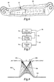
- a workflow diagram for FEA of scan-based geometry is generally designated 70. Similar to the CAD-based FEA workflow 10 in figure 1 , the scan-based workflow process 70 has three phases; namely, the acquisition phase 72, the refinement phase 74 and the evaluation phase 76. More specifically, the acquisition phase 72 consists of scanning a physical component to generate scan-based point cloud geometry, the refinement phase 74 consists of processing the scan-based point cloud geometry to generate scan-based geometry including scan-based surface geometry and/or scan-based solid geometry and the evaluation phase 76 consist of meshing the scan-based geometry to create scan-based FEA geometry which is suitable for execution of the FEA analysis.
- the acquisition phase 72 consists of scanning a physical component to generate scan-based point cloud geometry
- the refinement phase 74 consists of processing the scan-based point cloud geometry to generate scan-based geometry including scan-based surface geometry and/or scan-based solid geometry
- the evaluation phase 76 consist of meshing the scan-based geometry to create scan-based FEA geometry which is suitable for
- deviation checks are included in workflow process 70 which compare the scan-based geometry with the scan-based point cloud geometry in deviation check 78 and the scan-based FEA geometry with the scan-based point cloud geometry in deviation check 80 to ensure integrity of workflow process 70 through validation of the refinement phase 74 and the geometric portions of the evaluation phase 76.
- Three dimensional scanning system 100 for use during acquisition phase 72 of workflow process 70 is schematically illustrated.
- Three dimensional scanning system 100 utilizes a non-contact imaging system to capture the geometry of a component 102.
- three dimensional scanning system 100 is depicted as a laser scanning system that is operable to capture external component surfaces or line-of-sight component surfaces.
- laser scanning system 100 illuminates component 102 with a laser light source 104 and then receives the reflected light 106 with a camera sensor 108 at a fixed position relative to laser light source 104.
- Triangle ABC is formed by laser light source 104, camera sensor 108 and component 102. Angles 'a' and 'b' as well as distance 'C' are known. By the law of sines, the position of each point along the laser path may be computed.
- Some of the desired characteristics of three dimensional scan data are quality, accuracy and resolution.
- Data quality is measured by the amount of inherent noise in the collected data when compared against a true surface.
- Data accuracy is the measure of the trueness of the captured three dimensional features of the component geometry.
- Resolution is a measure of the smallest detail that can be reliably captured.
- One of the primary goals of three dimensional scanning is to generate three dimensional coordinates in a quantity sufficient to define the physical surface and reproduce the scanned component. Even though figure 8 depicts a particular type of three dimensional scanning system, it should be understood by those skilled in the art that other types of three dimensional scanning system are equally well suited for use with workflow process 70 such as structured light scanners, white/blue structured light scanners, computed tomography scanners or other suitable optical scanners.
- structured light three dimensional scanners compute positions by projecting a light pattern of lines or a grid on the component.
- the camera typically employs a two dimensional sensor while the emitted light pattern consists of lines.
- the camera imaging sensor detects the emitted light pattern, but the pattern is distorted where it intersects the three dimensional surface.
- the system compares the distortion to a nominal image (with no distortion) to derive the three dimensional surface geometry.
- the calculated result produces a three dimensional point cloud formed from the two dimensional grid projection on the component.
- three dimensional scanning systems can be automated for rapid data collection and are capable of achieving high resolution and accuracy.
- current three dimensional scanning systems are able to generate a high density point cloud representation of a scanned component with millions of data points wherein geometric details less than 0.002 in (0.051 mm) can be resolved.
- a rotorcraft component 112 is depicted as scan-based point cloud geometry in the form of three dimensional point cloud 110.
- Point cloud 110 is the raw data obtained in acquisition phase 72 of workflow process 70.
- Point cloud 110 may include millions of data points representing the geometry of component 112.
- the scan-based point cloud geometry is then used in the refinement phase 74 as the basis for creating scan-based geometry in the form of scan-based surface geometry and/or scan-based solid geometry.
- the scan-based point cloud geometry is used in validation steps by comparing the scan-based point cloud geometry with the scan-based geometry the in deviation check 78 and the scan-based FEA geometry in deviation check 80.
- the scan-based point cloud geometry may be filtered to remove any outliers and erroneous data, then point cloud 110 is preferably aligned with related CAD-based geometry to establish a coordinate system used during the finite element modeling. Once this is performed, all subsequent objects created will retain this coordinate system.
- the alignment may be accomplished, for example, by manual transformation, by a least-squares fit to a duplicate part or by feature alignment to datums or targets.
- a deviation plot 120 depicts a comparison between point cloud 110 and the CAD-based geometry of component 112 after a least-squares fit alignment. In the illustrated deviation plot, the density of the shading represents the level of deviation between point cloud 110 and the CAD-based geometry of component 112.
- This particular plot indicates there are significant differences between the nominal geometry and the geometry of the as-produced component that was scanned, for example, at locations 122, 124 where the shading has high density but little or no difference at location 126 where the shading has low density. It should be noted that if the alignment process used a different element or datum as the initial reference for matching the models, then the deviation between point cloud 110 and the CAD-based geometry of component 112 would be in different areas.
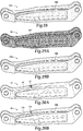
- points within point cloud 110 are connected using, for example, a polygon surface generation technique, as depicted in figure 11A .
- points of point cloud 110 are connected by a polygon surface consisting of a large plurality of triangles to form a polygon surface 130 representing a scan-based geometry of component 112.
- various automated software routines may be employed to correct defects such as holes, polygon mesh twists, sharp angles, sharp corners or disconnected components, such as those depicted at location 132, 134, 136 that may cause subsequent FEA operations to fail.
- triangle patches 138, 140, 142 have been added to correct discontinuities 132, 134, 136.
- Other operations to correct flaws or missing data include mirroring, offsetting, or growing/shrinking to compensate for paint or coating thicknesses.
- Features such as polygon cylinders may also be constructed and merged with the existing dataset.
- one or more deviation checks 78 may be conducted to ensure the original scan-based point cloud geometry is not altered in an unacceptable way and to validate the scan-based surface geometry.
- Additional processing of the scan-based surface geometry of component 112 may be accomplished by using, for example, fully parametric geometry, fully non-parametric geometry or hybrid geometry which utilizes a combination of parametric and non-parametric features.
- Parametric modeling describes surfaces with features such as an extruded circle and constraints such as a parallel relationship between two surfaces. The benefits to utilizing parametric modeling tools allows for quick modification of the geometry. Design integrity and assembly conflicts are more effectively managed through parametric models. Parametric modeling requires numerous steps to build and appropriately constrain features and, as a result, can require significantly long geometry build time as compared to non-parametric and hybrid modeling.
- Non-parametric modeling utilizes NURBS (Non-uniform rational basis spline) to create a mathematical surface which approximates the scan-based surface geometry.
- NURBS surfaces allow for complex geometry representations, however, features cannot be constrained to one another or resized as with parametric modeling.
- Software tools allow for creating automated non-parametric geometry which can result in extremely rapid build times.
- Hybrid modeling utilizes the best attributes of both parametric and non-parametric methods.
- geometry with non-parametric surfaces can be generated quickly, while parametric features are created only where needed, such as contacting surfaces and features which will be varied as part of subsequent FEA.
- Hybrid modeling is particularly attractive for large or complex shaped components in which fully parametric modeling is not feasible due to model build durations or where scan data may not be fully defined due to access limitations. For the latter, if enough of the feature has been captured then the missing portion may be approximated by a projection of the known data.
- component 112 is depicted in scan-based geometry 150 that has been further refined.
- additional processing steps may including creating contour lines on the surface of the component to form a skeleton that guides the construction of NURBS patches. Contour lines should be placed where there are changes in curvature to improve the accuracy in those areas.
- Software tools allow for manipulation of contour lines so that an acceptable result can be obtained. Patches are created to divide each contour region into a smaller subset of areas to match the polygon surface. During this operation, software tools allow modification of the created patches to ensure that patch boundaries and surface detail is adequately captured. Grids are created next which divide the patch boundary into many smaller segments that define the completed model surface resolution.
- the NURBS surface geometry is created over the patch and grid network. Throughout these refinement steps, one or more deviation checks 78 may be conducted to ensure the original scan-based point cloud geometry is not altered in an unacceptable way and to validate the various refinements of the scan-based geometry.
- the refinement phase 74 may include processing the scan-based surface geometry to form scan-based solid geometry.
- component 112 is depicted in scan-based geometry 160 as scan-based solid geometry with the detailed network of NURBS patches displayed thereon.
- it is preferable to verify the geometric integrity by performing another deviation comparison 78 of the scan-based geometry 160 with the original scan-based point cloud geometry.
- Evaluation phase 76 in process 70 is similar to that described herein with reference to the evaluation phase 16 of the CAD-based workflow process 10.
- the scan-based FEA includes numerous steps such as assignment of material properties, defining part interactions, meshing, application of boundary conditions/loads, solution computation and interpretation of results. There are some key differences, however, regarding meshing, part interactions, boundary conditions and load application for scan-based geometry.
- One of the objectives for evaluation phase 76 is to efficiently obtain accurate results. To support this goal, each step of the process should not consume more time than is needed for an appropriate level of accuracy for the model.
- Adjusting the pinch tolerance is a similar type of defeaturing method where a small line, for instance, is 'pinched' so that the line defined by two vertices becomes just one vertex and no line.
- the tolerance values must be chosen carefully so that detail is not lost in critical areas.
- Patch independent meshing is another effective way to manage unnecessary complexity in the scan-based geometry.
- This meshing algorithm is less sensitive to small surface features and flaws because the mesh is generated first from the volume and the geometric boundary data is used to define the surface mesh. Similar defeaturing tolerances are available for patch independent meshes and the same care must be employed to avoid losing detail in critical areas.
- Another advanced mesh control suitable for scan-based geometry is curvature priority meshing which automatically concentrates mesh density at areas of high curvature.
- the curvature priority method can save some meshing time but comes with the cost of added computation time because elements are added everywhere high curvature exists. For smaller models the added computational cost is minimal but for larger models a more careful control of element count may be needed.
- tetrahedron meshes generally have larger node/element counts but are easier to generate than hexahedron meshes so a choice must be made between savings in mesh time or solve time.
- deviation check 80 should be performed comparing the final scan-based FEA geometry and the original scan-based point cloud geometry to validate the scan-based FEA geometry.
- a rotorcraft component 18 displaying thereon scan-based FEA data in the form of a stress map 170 is depicted.
- rotorcraft component 18 has a manufacturing defect 204 in the form of missing material that occurred as a result of a forging process.
- Rotorcraft component 18 was subjected to workflow process 70 including the acquisition phase 72 wherein an as-produced rotorcraft component with a defect was scanned to obtain scan-based point cloud geometry, the refinement phase 74 wherein the scan-based point cloud geometry was processed to obtain scan-based geometry and the evaluation phase 76 wherein the scan-based geometry was analyzed to obtain scan-based FEA geometry and stress related FEA data.
- component 18 includes a stress concentration 176.
- a rotorcraft component having a particular defect has been depicted and described, it should be understood by those skilled in the art that any type of component, with or without a defect, whether new or used, could alternatively be subject to workflow process 70 including, but not limited to, OEM components, aftermarket components, cast components, machined components, test part components, components having weldments, components having irregular geometries, components having batch defects, repaired components, damaged components or other mechanical components.
- FIG. 13 illustrates how CAD-based and scan-based FEA may be combined into a single interrelated workflow process 180.
- CAD-based workflow process 10 includes the acquisition phase 12, the refinement phase 14 and the evaluation phase 16.
- the scan-based workflow process 70 includes the acquisition phase 72, the refinement phase 74 and the evaluation phase 76.
- the scan-based workflow process 70 includes deviation checks 78 which compare the scan-based point cloud geometry with the scan-based geometry and deviation check 80 which compares the scan-based point cloud geometry with scan-based FEA geometry to ensure integrity of the scan-based workflow process.
- One of the strengths of the combined workflow process 180 is the addition of further steps that establish a relationship between the CAD-based and scan-based geometries; namely, the alignment phase 182, the deviation phase 184 and result comparison phase 186.
- CAD-based geometry 200 of component 18 and an as-produced unit 202 of component 18 are depicted, respectively.
- CAD-based geometry 200 represents the nominal condition of component 18 as designed.
- As-produced unit 202 is an actual component 18 manufactured using a forging process that includes a defect 204 in the form of missing material along an upper corner surface of component 18. It should be noted that one or more lots of dozens or hundreds of as-produced units 202 with defect 204 could have been manufactured due to a deviation in the manufacturing process or processes.
- defect 204 may have little or no effect on the stress concentrations experienced by component 18 during operation such as when defect 204 is sufficiently remote from such stress concentrations in accordance with Saint Venant's Principle.
- CAD-based geometry, refined CAD-based geometry, CAD-based FEA geometry and CAD-based FEA data were previously developed during the design process associated with component 18.
- the CAD-based geometry was used in the production process, however, as-produced unit 202 nonetheless has defect 204.
- the actual surface geometry of as-produced unit 202 is reproduced using a scanning system, such as three dimensional scanning system 100, as discussed herein.
- the scanning process yields scan-based point cloud geometry of as-produced unit 202 with defect 204, as discussed herein.
- the next step in combined workflow process 180 is the alignment phase 182 in which the scan-based point cloud geometry of as-produced unit 202 with defect 204 is align with CAD-based geometry 200 of component 18.
- alignment can be achieved by various methods.
- the alignment phase 182 includes an important deviation check wherein the scan-based point cloud geometry is viewed together with the CAD-based geometry in a deviation plot 210. As illustrated, this particular plot indicates there is a significant difference between the nominal geometry and the geometry of the as-produced component along the defect 204 as indicated by high density shading but little or no difference throughout the reminder of component 18 as indicated by low density shading.
- the alignment phase 182 not only establishes a coordinate system upon which to base the FEA analysis, it also establishes a relationship whereby the difference between the CAD-based and scan-based geometries may be quantified.
- the scan-based point cloud geometry of as-produced unit 202 with defect 204 may then be imported directly into the duplicate CAD-based model and prepared for analysis in place of the CAD-based geometry. This aligned position also allows for easy modification of the surfaces for part interactions, boundary conditions, and load application by using the corresponding CAD surfaces as guides.
- the refinement phase 74 may include a variety of processes such as performing a polygon surface generation technique, correcting discontinuities and other flaws, incorporating parametric data, manipulating non-parametric geometry and using hybrid modeling to create the scan-based geometry of as-produced unit 202 with defect 204.
- the refinement phase 74 may include one or more deviation checks 78 (see figure 13 ) wherein the scan-based geometry is compared to the scan-based point cloud geometry in a deviation plot. As illustrated in figure 16A , the detailed network of NURBS patches is shown on the scan-based geometry 220 of component 18.
- a deviation plot 222 in figure 16B includes high density shading along defect 204 indicating a deviation of, for example, more than 0.01 inches.
- the acceptable level of deviation has been determined to be less than 0.002 inches, which represents the noise level of the scanning process or the smallest geometric detail that the scanning system is capable of resolving.
- additional or alternative processing in the refinement phase 74 should be performed.
- the deviation plot 232 in figure 17B includes low density shading along defect 204, as well as on the entire component, indicating a deviation of, for example, less than 0.002 inches which is within the predetermined acceptable level of deviation.
- Deviation plot 240 forms the basis for rationalizing the differences in FEA results observed following the evaluation phase 76. As illustrated, this particular plot indicates there is a significant difference between the CAD-based geometry and the scan-based geometry, as excepted, along the defect 204 as indicated by high density shading but little or no difference throughout the reminder of component 18, as indicated by low density shading. It should be noted that information obtained from deviation plot 240 may serve as a guide to further modification of the scan data to explore the component's geometric sensitivities.
- the evaluation phase 76 may include numerous steps such as assignment of material properties, defining part interactions, meshing, application of boundary conditions/loads, solution computation and interpretation of results.
- the evaluation phase 76 includes an important deviation check 80 (see figure 13 ) wherein the scan-based FEA geometry 250 is compared to the scan-based point cloud geometry in a deviation plot 252.
- the detailed mesh network is shown on the scan-based FEA geometry 250 of component 18.
- the deviation plot 252 in figure 19B includes low density shading along defect 204, as well as on the entire component, indicating a deviation of, for example, less than 0.002 inches which is within the predetermined acceptable level of deviation.
- the evaluation phase 76 also includes, in this example, generation of FEA data relating to stress on component 18 during a certain operation.
- the FEA software generates a stress map that is visible on component 18.
- CAD-based FEA data 60 is mapped on component 18 in figure 20A and scan-based FEA data 170 is mapped on component 18 with defect 204 in figure 20B .
- the CAD-based FEA data 60 reveals stress concentration 62.
- the magnitude of stress at stress concentration 62 is below the acceptable design stress level thus, the CAD-based geometry for the design of component 18 was approved.
- as-produced component 202 included the defect 204 which was outside of the design criteria, as-produced component 202 was subjected to combined workflow process 180 which resulted in the generation of scan-based FEA data 170. As previously discussed with reference to figure 12 , the scan-based FEA data 170 reveals stress concentration 176.
- the result comparison phase 186 the CAD-based FEA data 60 and scan-based FEA data 170 should be compared to identify the effect of the geometric difference between the CAD-based and scan-based geometries. Any unexplained difference between the two may indicate a problem with the analysis which would require further investigation.
- the result comparison phase 186 serves to validate the scan-based FEA data when similar results exist for similar geometric features.
- the magnitude of stress at stress concentration 176 is lower than the magnitude of stress at stress concentration 62. This difference is the key information and serves to indicate the stress in as-produced component 202 including the defect 204 is below the acceptable design stress level and thus, as-produced component 202 including the defect 204 may be qualified for use.
- defect 204 in as-produced units 202 does not affect critical design performance criteria of component 18.
- similar as-produced units with defect 204 could be qualified for use instead of scrapped.
- as-produced component 202 does not conform exactly to the design criteria exemplified by the CAD-based geometry, through use of the combined workflow process 180, it has nonetheless been found to be suitable for its intended purpose and may be qualified for use.
- workflow process 70 includes the acquisition phase 72, the refinement phase 74 and the evaluation phase 76, such data may be used as a baseline during a combined workflow process relating to a similar component.
- the previous scan-based data could take the place of the CAD-based data in combined workflow process 180 described herein providing many of the same benefits.
- Use of the previous scan-based FEA with subsequent scan-based FEA may be particularly useful in scenarios involving damaged components, repaired components and components having batch defects.
Landscapes
- Engineering & Computer Science (AREA)
- Physics & Mathematics (AREA)
- Theoretical Computer Science (AREA)
- Geometry (AREA)
- General Physics & Mathematics (AREA)
- Evolutionary Computation (AREA)
- General Engineering & Computer Science (AREA)
- Computer Hardware Design (AREA)
- Computational Mathematics (AREA)
- Mathematical Analysis (AREA)
- Mathematical Optimization (AREA)
- Pure & Applied Mathematics (AREA)
- Testing Of Devices, Machine Parts, Or Other Structures Thereof (AREA)
Applications Claiming Priority (2)
| Application Number | Priority Date | Filing Date | Title |
|---|---|---|---|
| US201562146840P | 2015-04-13 | 2015-04-13 | |
| US15/092,969 US10289770B2 (en) | 2015-04-13 | 2016-04-07 | Rotorcraft component simulation using scan-based geometry |
Publications (2)
| Publication Number | Publication Date |
|---|---|
| EP3082055A1 true EP3082055A1 (fr) | 2016-10-19 |
| EP3082055B1 EP3082055B1 (fr) | 2018-07-18 |
Family
ID=55745674
Family Applications (1)
| Application Number | Title | Priority Date | Filing Date |
|---|---|---|---|
| EP16164943.9A Active EP3082055B1 (fr) | 2015-04-13 | 2016-04-12 | Simulation de composant de giravion utilisant une géométrie à balayage |
Country Status (2)
| Country | Link |
|---|---|
| US (1) | US10289770B2 (fr) |
| EP (1) | EP3082055B1 (fr) |
Cited By (2)
| Publication number | Priority date | Publication date | Assignee | Title |
|---|---|---|---|---|
| CN108664689A (zh) * | 2017-03-28 | 2018-10-16 | 赫克斯冈技术中心 | 用于生成模拟模型的方法 |
| CN109918755A (zh) * | 2019-02-28 | 2019-06-21 | 大连理工大学 | 一种基于点云数据的低刚度制件装配变形预测方法 |
Families Citing this family (18)
| Publication number | Priority date | Publication date | Assignee | Title |
|---|---|---|---|---|
| US9002719B2 (en) | 2012-10-08 | 2015-04-07 | State Farm Mutual Automobile Insurance Company | Device and method for building claim assessment |
| US8872818B2 (en) * | 2013-03-15 | 2014-10-28 | State Farm Mutual Automobile Insurance Company | Methods and systems for capturing the condition of a physical structure |
| US10471651B2 (en) * | 2014-06-04 | 2019-11-12 | Mitsubishi Hitachi Power Systems, Ltd. | Repair system, repair-data providing apparatus and repair-data generation method |
| US10176527B1 (en) | 2016-04-27 | 2019-01-08 | State Farm Mutual Automobile Insurance Company | Providing shade for optical detection of structural features |
| US10747917B1 (en) | 2016-11-08 | 2020-08-18 | Bell Helicopter Textron Inc. | Method for generating a simulation model to evaluate aircraft flight systems |
| TWI659205B (zh) * | 2017-09-19 | 2019-05-11 | 財團法人工業技術研究院 | 即位量測系統、基準校準方法、誤差量測方法與電腦可讀取記錄媒體 |
| CN108090962B (zh) * | 2017-11-14 | 2022-11-18 | 中国核电工程有限公司 | 基于ansys数据文件的plaxis几何模型快速生成方法 |
| US11049236B2 (en) * | 2017-11-17 | 2021-06-29 | Kodak Alaris Inc. | Automated in-line object inspection |
| US11042146B2 (en) | 2017-11-17 | 2021-06-22 | Kodak Alaris Inc. | Automated 360-degree dense point object inspection |
| CN109783854B (zh) * | 2018-12-11 | 2023-07-21 | 浙江深康汽车车身模具有限公司 | 扫描点云与数字cad曲面位移偏差提取方法 |
| KR102791536B1 (ko) * | 2019-03-21 | 2025-04-03 | 현대자동차주식회사 | 자동차용 시트 정합성 자동 평가 시스템 및 방법, 이를 실행하기 위한 프로그램이 기록된 기록매체 |
| CN112297435B (zh) * | 2019-07-26 | 2024-06-18 | 哈米尔顿森德斯特兰德公司 | 空间差异测量 |
| CN111209639B (zh) * | 2020-02-17 | 2024-05-03 | 合肥工业大学 | 一种叶轮-轴承-转子系统的高效定量建模方法 |
| CN112161566B (zh) * | 2020-09-27 | 2021-11-12 | 西安电子科技大学 | 一种基于模型的零件制造质量智能检测方法 |
| EP4352634A4 (fr) | 2021-05-31 | 2025-04-16 | Abyss Solutions Pty Ltd | Procédé et système de détection de déformation de surface |
| JP2024024510A (ja) * | 2022-08-09 | 2024-02-22 | 株式会社キーエンス | リバースエンジニアリング支援装置 |
| JP2024063579A (ja) * | 2022-10-26 | 2024-05-13 | 株式会社日立製作所 | 製造設備の設計支援装置並びに設計支援方法 |
| CN116000453B (zh) * | 2023-03-06 | 2023-09-26 | 深圳精科视觉科技有限公司 | 一种激光焊接质量实时监控方法及系统 |
Citations (3)
| Publication number | Priority date | Publication date | Assignee | Title |
|---|---|---|---|---|
| EP0875751A1 (fr) * | 1997-05-02 | 1998-11-04 | General Electric Company | Tomographie assistée par ordinateur et métrologie |
| US20040254758A1 (en) * | 2003-05-28 | 2004-12-16 | Chih-Kuang Chang | System and method for detecting defects of objects based on a CAD platform |
| CN104282040A (zh) * | 2014-09-29 | 2015-01-14 | 北京航空航天大学 | 一种用于三维实体模型重建的有限元前处理方法 |
Family Cites Families (3)
| Publication number | Priority date | Publication date | Assignee | Title |
|---|---|---|---|---|
| GB201408925D0 (en) * | 2014-05-20 | 2014-07-02 | Rolls Royce Plc | Finite element mesh customisation |
| US10409932B2 (en) * | 2014-09-19 | 2019-09-10 | Siemens Product Lifecyle Management Software Inc. | Computer-aided simulation of multi-layer selective laser sintering and melting additive manufacturing processes |
| WO2016087915A2 (fr) * | 2014-12-05 | 2016-06-09 | Mantisvision Ltd. | Repères pour la capture de données 3d |
-
2016
- 2016-04-07 US US15/092,969 patent/US10289770B2/en active Active
- 2016-04-12 EP EP16164943.9A patent/EP3082055B1/fr active Active
Patent Citations (3)
| Publication number | Priority date | Publication date | Assignee | Title |
|---|---|---|---|---|
| EP0875751A1 (fr) * | 1997-05-02 | 1998-11-04 | General Electric Company | Tomographie assistée par ordinateur et métrologie |
| US20040254758A1 (en) * | 2003-05-28 | 2004-12-16 | Chih-Kuang Chang | System and method for detecting defects of objects based on a CAD platform |
| CN104282040A (zh) * | 2014-09-29 | 2015-01-14 | 北京航空航天大学 | 一种用于三维实体模型重建的有限元前处理方法 |
Non-Patent Citations (2)
| Title |
|---|
| L. BARAZZETTI ET AL: "BIM FROM LASER CLOUDS AND FINITE ELEMENT ANALYSIS: COMBINING STRUCTURAL ANALYSIS AND GEOMETRIC COMPLEXITY", ISPRS - INTERNATIONAL ARCHIVES OF THE PHOTOGRAMMETRY, REMOTE SENSING AND SPATIAL INFORMATION SCIENCES, vol. XL-5/W4, 19 February 2015 (2015-02-19), pages 345 - 350, XP055289478, DOI: 10.5194/isprsarchives-XL-5-W4-345-2015 * |
| MOBLEY A V ET AL: "An object oriented approach to geometry defeaturing for finite element meshing", 26 October 1998, 7TH INTERNATIONAL MESHING ROUNDTABLE, SANDIA NATIONAL LABORATORIES, PAGES 547-563, XP002378996 * |
Cited By (3)
| Publication number | Priority date | Publication date | Assignee | Title |
|---|---|---|---|---|
| CN108664689A (zh) * | 2017-03-28 | 2018-10-16 | 赫克斯冈技术中心 | 用于生成模拟模型的方法 |
| EP3382582B1 (fr) * | 2017-03-28 | 2022-09-28 | Hexagon Technology Center GmbH | Procédé de génération d'un modèle de simulation |
| CN109918755A (zh) * | 2019-02-28 | 2019-06-21 | 大连理工大学 | 一种基于点云数据的低刚度制件装配变形预测方法 |
Also Published As
| Publication number | Publication date |
|---|---|
| EP3082055B1 (fr) | 2018-07-18 |
| US20160300003A1 (en) | 2016-10-13 |
| US10289770B2 (en) | 2019-05-14 |
Similar Documents
| Publication | Publication Date | Title |
|---|---|---|
| US10289770B2 (en) | Rotorcraft component simulation using scan-based geometry | |
| EP3877887B1 (fr) | Conversion de géométrie de conception générative en représentation de limite modifiable et étanche dans une conception assistée par ordinateur | |
| CN111145236B (zh) | 一种基于数字孪生的产品拟实物装配模型生成方法及实现框架 | |
| Pathak et al. | Framework for automated GD&T inspection using 3D scanner | |
| US20090136114A1 (en) | Multi-modality inspection method with data validation and data fusion | |
| Su et al. | Accurate model construction of deformed aero-engine blades for remanufacturing | |
| Heinze et al. | A parametric model for probabilistic analysis of turbine blades considering real geometric effects | |
| US12135923B2 (en) | Morphing of watertight spline models using manufacturing data, inspection data, and product manufacturing information | |
| Korbi et al. | CAD/tolerancing integration: a new approach for tolerance analysis of non-rigid parts assemblies | |
| Moroni et al. | Geometric inspection planning as a key element in industry 4.0 | |
| CN118098447A (zh) | 一种预测弱刚性复合材料结构装配变形规律的方法 | |
| Ghorbani et al. | Accurate registration of point clouds of damaged aeroengine blades | |
| US20120303333A1 (en) | System and method for non-destructive testing | |
| Wu et al. | A model reconstruction method of blade repair based on linear combination | |
| EP4016073B1 (fr) | Détection d'incohérence structurelle à l'aide de données de distance | |
| JP2003196326A (ja) | 形状モデル作成装置及び方法 | |
| US11410383B2 (en) | Automated component design extraction | |
| US10818085B1 (en) | Systems and methods for 3D tolerance analysis | |
| Sánchez et al. | Fast and accurate mesh registration applied to in-line dimensional inspection processes | |
| EP3734219B1 (fr) | Système et méthode de détermination de la viabilité et de la durée de vie restante d'une structure en service à l'aide de données de balayage tridimensionnel | |
| Chen et al. | Idealization of scanning-derived triangle mesh models of prismatic engineering parts | |
| CN113405494B (zh) | 用于自动产生测试计划的计算机实施的方法 | |
| CN116258667A (zh) | 用于交通工具的无损检测的分析数字孪生体 | |
| Maiorova et al. | IMPLEMENTATION OF REENGINEERING TECHNOLOGY IN THE TECHNOLOGICAL PREPARATION FOR GENERAL AVIATION AIRPLANE WING TIP MANUFACTURING BASED ON THE CONSTRUCTION OF A DIGITAL MOCK-UP. | |
| Ko et al. | Accommodating Casting and Fixturing Errors by Adjusting the Machining Coordinate Frame |
Legal Events
| Date | Code | Title | Description |
|---|---|---|---|
| PUAI | Public reference made under article 153(3) epc to a published international application that has entered the european phase |
Free format text: ORIGINAL CODE: 0009012 |
|
| 17P | Request for examination filed |
Effective date: 20160412 |
|
| AK | Designated contracting states |
Kind code of ref document: A1 Designated state(s): AL AT BE BG CH CY CZ DE DK EE ES FI FR GB GR HR HU IE IS IT LI LT LU LV MC MK MT NL NO PL PT RO RS SE SI SK SM TR |
|
| AX | Request for extension of the european patent |
Extension state: BA ME |
|
| STAA | Information on the status of an ep patent application or granted ep patent |
Free format text: STATUS: EXAMINATION IS IN PROGRESS |
|
| GRAP | Despatch of communication of intention to grant a patent |
Free format text: ORIGINAL CODE: EPIDOSNIGR1 |
|
| STAA | Information on the status of an ep patent application or granted ep patent |
Free format text: STATUS: GRANT OF PATENT IS INTENDED |
|
| GRAS | Grant fee paid |
Free format text: ORIGINAL CODE: EPIDOSNIGR3 |
|
| INTG | Intention to grant announced |
Effective date: 20180508 |
|
| GRAA | (expected) grant |
Free format text: ORIGINAL CODE: 0009210 |
|
| STAA | Information on the status of an ep patent application or granted ep patent |
Free format text: STATUS: THE PATENT HAS BEEN GRANTED |
|
| AK | Designated contracting states |
Kind code of ref document: B1 Designated state(s): AL AT BE BG CH CY CZ DE DK EE ES FI FR GB GR HR HU IE IS IT LI LT LU LV MC MK MT NL NO PL PT RO RS SE SI SK SM TR |
|
| REG | Reference to a national code |
Ref country code: GB Ref legal event code: FG4D |
|
| REG | Reference to a national code |
Ref country code: CH Ref legal event code: EP |
|
| REG | Reference to a national code |
Ref country code: IE Ref legal event code: FG4D |
|
| REG | Reference to a national code |
Ref country code: AT Ref legal event code: REF Ref document number: 1020108 Country of ref document: AT Kind code of ref document: T Effective date: 20180815 |
|
| REG | Reference to a national code |
Ref country code: DE Ref legal event code: R096 Ref document number: 602016004052 Country of ref document: DE |
|
| REG | Reference to a national code |
Ref country code: NL Ref legal event code: MP Effective date: 20180718 |
|
| REG | Reference to a national code |
Ref country code: LT Ref legal event code: MG4D |
|
| REG | Reference to a national code |
Ref country code: AT Ref legal event code: MK05 Ref document number: 1020108 Country of ref document: AT Kind code of ref document: T Effective date: 20180718 |
|
| PG25 | Lapsed in a contracting state [announced via postgrant information from national office to epo] |
Ref country code: NL Free format text: LAPSE BECAUSE OF FAILURE TO SUBMIT A TRANSLATION OF THE DESCRIPTION OR TO PAY THE FEE WITHIN THE PRESCRIBED TIME-LIMIT Effective date: 20180718 |
|
| PG25 | Lapsed in a contracting state [announced via postgrant information from national office to epo] |
Ref country code: GR Free format text: LAPSE BECAUSE OF FAILURE TO SUBMIT A TRANSLATION OF THE DESCRIPTION OR TO PAY THE FEE WITHIN THE PRESCRIBED TIME-LIMIT Effective date: 20181019 Ref country code: NO Free format text: LAPSE BECAUSE OF FAILURE TO SUBMIT A TRANSLATION OF THE DESCRIPTION OR TO PAY THE FEE WITHIN THE PRESCRIBED TIME-LIMIT Effective date: 20181018 Ref country code: FI Free format text: LAPSE BECAUSE OF FAILURE TO SUBMIT A TRANSLATION OF THE DESCRIPTION OR TO PAY THE FEE WITHIN THE PRESCRIBED TIME-LIMIT Effective date: 20180718 Ref country code: SE Free format text: LAPSE BECAUSE OF FAILURE TO SUBMIT A TRANSLATION OF THE DESCRIPTION OR TO PAY THE FEE WITHIN THE PRESCRIBED TIME-LIMIT Effective date: 20180718 Ref country code: LT Free format text: LAPSE BECAUSE OF FAILURE TO SUBMIT A TRANSLATION OF THE DESCRIPTION OR TO PAY THE FEE WITHIN THE PRESCRIBED TIME-LIMIT Effective date: 20180718 Ref country code: IS Free format text: LAPSE BECAUSE OF FAILURE TO SUBMIT A TRANSLATION OF THE DESCRIPTION OR TO PAY THE FEE WITHIN THE PRESCRIBED TIME-LIMIT Effective date: 20181118 Ref country code: RS Free format text: LAPSE BECAUSE OF FAILURE TO SUBMIT A TRANSLATION OF THE DESCRIPTION OR TO PAY THE FEE WITHIN THE PRESCRIBED TIME-LIMIT Effective date: 20180718 Ref country code: PL Free format text: LAPSE BECAUSE OF FAILURE TO SUBMIT A TRANSLATION OF THE DESCRIPTION OR TO PAY THE FEE WITHIN THE PRESCRIBED TIME-LIMIT Effective date: 20180718 Ref country code: BG Free format text: LAPSE BECAUSE OF FAILURE TO SUBMIT A TRANSLATION OF THE DESCRIPTION OR TO PAY THE FEE WITHIN THE PRESCRIBED TIME-LIMIT Effective date: 20181018 Ref country code: AT Free format text: LAPSE BECAUSE OF FAILURE TO SUBMIT A TRANSLATION OF THE DESCRIPTION OR TO PAY THE FEE WITHIN THE PRESCRIBED TIME-LIMIT Effective date: 20180718 |
|
| PG25 | Lapsed in a contracting state [announced via postgrant information from national office to epo] |
Ref country code: AL Free format text: LAPSE BECAUSE OF FAILURE TO SUBMIT A TRANSLATION OF THE DESCRIPTION OR TO PAY THE FEE WITHIN THE PRESCRIBED TIME-LIMIT Effective date: 20180718 Ref country code: LV Free format text: LAPSE BECAUSE OF FAILURE TO SUBMIT A TRANSLATION OF THE DESCRIPTION OR TO PAY THE FEE WITHIN THE PRESCRIBED TIME-LIMIT Effective date: 20180718 Ref country code: HR Free format text: LAPSE BECAUSE OF FAILURE TO SUBMIT A TRANSLATION OF THE DESCRIPTION OR TO PAY THE FEE WITHIN THE PRESCRIBED TIME-LIMIT Effective date: 20180718 |
|
| REG | Reference to a national code |
Ref country code: DE Ref legal event code: R097 Ref document number: 602016004052 Country of ref document: DE |
|
| PG25 | Lapsed in a contracting state [announced via postgrant information from national office to epo] |
Ref country code: EE Free format text: LAPSE BECAUSE OF FAILURE TO SUBMIT A TRANSLATION OF THE DESCRIPTION OR TO PAY THE FEE WITHIN THE PRESCRIBED TIME-LIMIT Effective date: 20180718 Ref country code: ES Free format text: LAPSE BECAUSE OF FAILURE TO SUBMIT A TRANSLATION OF THE DESCRIPTION OR TO PAY THE FEE WITHIN THE PRESCRIBED TIME-LIMIT Effective date: 20180718 Ref country code: RO Free format text: LAPSE BECAUSE OF FAILURE TO SUBMIT A TRANSLATION OF THE DESCRIPTION OR TO PAY THE FEE WITHIN THE PRESCRIBED TIME-LIMIT Effective date: 20180718 Ref country code: CZ Free format text: LAPSE BECAUSE OF FAILURE TO SUBMIT A TRANSLATION OF THE DESCRIPTION OR TO PAY THE FEE WITHIN THE PRESCRIBED TIME-LIMIT Effective date: 20180718 |
|
| PLBE | No opposition filed within time limit |
Free format text: ORIGINAL CODE: 0009261 |
|
| STAA | Information on the status of an ep patent application or granted ep patent |
Free format text: STATUS: NO OPPOSITION FILED WITHIN TIME LIMIT |
|
| PG25 | Lapsed in a contracting state [announced via postgrant information from national office to epo] |
Ref country code: SM Free format text: LAPSE BECAUSE OF FAILURE TO SUBMIT A TRANSLATION OF THE DESCRIPTION OR TO PAY THE FEE WITHIN THE PRESCRIBED TIME-LIMIT Effective date: 20180718 Ref country code: DK Free format text: LAPSE BECAUSE OF FAILURE TO SUBMIT A TRANSLATION OF THE DESCRIPTION OR TO PAY THE FEE WITHIN THE PRESCRIBED TIME-LIMIT Effective date: 20180718 Ref country code: SK Free format text: LAPSE BECAUSE OF FAILURE TO SUBMIT A TRANSLATION OF THE DESCRIPTION OR TO PAY THE FEE WITHIN THE PRESCRIBED TIME-LIMIT Effective date: 20180718 |
|
| 26N | No opposition filed |
Effective date: 20190423 |
|
| PG25 | Lapsed in a contracting state [announced via postgrant information from national office to epo] |
Ref country code: SI Free format text: LAPSE BECAUSE OF FAILURE TO SUBMIT A TRANSLATION OF THE DESCRIPTION OR TO PAY THE FEE WITHIN THE PRESCRIBED TIME-LIMIT Effective date: 20180718 |
|
| REG | Reference to a national code |
Ref country code: DE Ref legal event code: R079 Ref document number: 602016004052 Country of ref document: DE Free format text: PREVIOUS MAIN CLASS: G06F0017500000 Ipc: G06F0030000000 |
|
| REG | Reference to a national code |
Ref country code: CH Ref legal event code: PL |
|
| REG | Reference to a national code |
Ref country code: BE Ref legal event code: MM Effective date: 20190430 |
|
| PG25 | Lapsed in a contracting state [announced via postgrant information from national office to epo] |
Ref country code: LU Free format text: LAPSE BECAUSE OF NON-PAYMENT OF DUE FEES Effective date: 20190412 Ref country code: MC Free format text: LAPSE BECAUSE OF FAILURE TO SUBMIT A TRANSLATION OF THE DESCRIPTION OR TO PAY THE FEE WITHIN THE PRESCRIBED TIME-LIMIT Effective date: 20180718 |
|
| PG25 | Lapsed in a contracting state [announced via postgrant information from national office to epo] |
Ref country code: LI Free format text: LAPSE BECAUSE OF NON-PAYMENT OF DUE FEES Effective date: 20190430 Ref country code: CH Free format text: LAPSE BECAUSE OF NON-PAYMENT OF DUE FEES Effective date: 20190430 |
|
| PG25 | Lapsed in a contracting state [announced via postgrant information from national office to epo] |
Ref country code: BE Free format text: LAPSE BECAUSE OF NON-PAYMENT OF DUE FEES Effective date: 20190430 |
|
| PG25 | Lapsed in a contracting state [announced via postgrant information from national office to epo] |
Ref country code: TR Free format text: LAPSE BECAUSE OF FAILURE TO SUBMIT A TRANSLATION OF THE DESCRIPTION OR TO PAY THE FEE WITHIN THE PRESCRIBED TIME-LIMIT Effective date: 20180718 |
|
| PG25 | Lapsed in a contracting state [announced via postgrant information from national office to epo] |
Ref country code: IE Free format text: LAPSE BECAUSE OF NON-PAYMENT OF DUE FEES Effective date: 20190412 |
|
| PG25 | Lapsed in a contracting state [announced via postgrant information from national office to epo] |
Ref country code: PT Free format text: LAPSE BECAUSE OF FAILURE TO SUBMIT A TRANSLATION OF THE DESCRIPTION OR TO PAY THE FEE WITHIN THE PRESCRIBED TIME-LIMIT Effective date: 20181118 |
|
| PG25 | Lapsed in a contracting state [announced via postgrant information from national office to epo] |
Ref country code: CY Free format text: LAPSE BECAUSE OF FAILURE TO SUBMIT A TRANSLATION OF THE DESCRIPTION OR TO PAY THE FEE WITHIN THE PRESCRIBED TIME-LIMIT Effective date: 20180718 |
|
| PG25 | Lapsed in a contracting state [announced via postgrant information from national office to epo] |
Ref country code: MT Free format text: LAPSE BECAUSE OF FAILURE TO SUBMIT A TRANSLATION OF THE DESCRIPTION OR TO PAY THE FEE WITHIN THE PRESCRIBED TIME-LIMIT Effective date: 20180718 Ref country code: HU Free format text: LAPSE BECAUSE OF FAILURE TO SUBMIT A TRANSLATION OF THE DESCRIPTION OR TO PAY THE FEE WITHIN THE PRESCRIBED TIME-LIMIT; INVALID AB INITIO Effective date: 20160412 |
|
| PG25 | Lapsed in a contracting state [announced via postgrant information from national office to epo] |
Ref country code: MK Free format text: LAPSE BECAUSE OF FAILURE TO SUBMIT A TRANSLATION OF THE DESCRIPTION OR TO PAY THE FEE WITHIN THE PRESCRIBED TIME-LIMIT Effective date: 20180718 |
|
| P01 | Opt-out of the competence of the unified patent court (upc) registered |
Effective date: 20230602 |
|
| PGFP | Annual fee paid to national office [announced via postgrant information from national office to epo] |
Ref country code: DE Payment date: 20250429 Year of fee payment: 10 |
|
| PGFP | Annual fee paid to national office [announced via postgrant information from national office to epo] |
Ref country code: GB Payment date: 20250428 Year of fee payment: 10 |
|
| PGFP | Annual fee paid to national office [announced via postgrant information from national office to epo] |
Ref country code: IT Payment date: 20250422 Year of fee payment: 10 |
|
| PGFP | Annual fee paid to national office [announced via postgrant information from national office to epo] |
Ref country code: FR Payment date: 20250425 Year of fee payment: 10 |