EP3082131A1 - Haltevorrichtung eines absorbierenden stabs zur kontrolle eines kernreaktors - Google Patents
Haltevorrichtung eines absorbierenden stabs zur kontrolle eines kernreaktors Download PDFInfo
- Publication number
- EP3082131A1 EP3082131A1 EP16164791.2A EP16164791A EP3082131A1 EP 3082131 A1 EP3082131 A1 EP 3082131A1 EP 16164791 A EP16164791 A EP 16164791A EP 3082131 A1 EP3082131 A1 EP 3082131A1
- Authority
- EP
- European Patent Office
- Prior art keywords
- control rod
- bar
- magnetic
- external component
- rod
- Prior art date
- Legal status (The legal status is an assumption and is not a legal conclusion. Google has not performed a legal analysis and makes no representation as to the accuracy of the status listed.)
- Granted
Links
Images




Classifications
-
- G—PHYSICS
- G21—NUCLEAR PHYSICS; NUCLEAR ENGINEERING
- G21C—NUCLEAR REACTORS
- G21C19/00—Arrangements for treating, for handling, or for facilitating the handling of, fuel or other materials which are used within the reactor, e.g. within its pressure vessel
- G21C19/02—Details of handling arrangements
- G21C19/06—Magazines for holding fuel elements or control elements
-
- G—PHYSICS
- G21—NUCLEAR PHYSICS; NUCLEAR ENGINEERING
- G21C—NUCLEAR REACTORS
- G21C7/00—Control of nuclear reaction
- G21C7/06—Control of nuclear reaction by application of neutron-absorbing material, i.e. material with absorption cross-section very much in excess of reflection cross-section
- G21C7/08—Control of nuclear reaction by application of neutron-absorbing material, i.e. material with absorption cross-section very much in excess of reflection cross-section by displacement of solid control elements, e.g. control rods
- G21C7/10—Construction of control elements
-
- G—PHYSICS
- G21—NUCLEAR PHYSICS; NUCLEAR ENGINEERING
- G21C—NUCLEAR REACTORS
- G21C7/00—Control of nuclear reaction
- G21C7/06—Control of nuclear reaction by application of neutron-absorbing material, i.e. material with absorption cross-section very much in excess of reflection cross-section
- G21C7/08—Control of nuclear reaction by application of neutron-absorbing material, i.e. material with absorption cross-section very much in excess of reflection cross-section by displacement of solid control elements, e.g. control rods
- G21C7/12—Means for moving control elements to desired position
-
- G—PHYSICS
- G21—NUCLEAR PHYSICS; NUCLEAR ENGINEERING
- G21C—NUCLEAR REACTORS
- G21C7/00—Control of nuclear reaction
- G21C7/06—Control of nuclear reaction by application of neutron-absorbing material, i.e. material with absorption cross-section very much in excess of reflection cross-section
- G21C7/08—Control of nuclear reaction by application of neutron-absorbing material, i.e. material with absorption cross-section very much in excess of reflection cross-section by displacement of solid control elements, e.g. control rods
- G21C7/12—Means for moving control elements to desired position
- G21C7/14—Mechanical drive arrangements
-
- G—PHYSICS
- G21—NUCLEAR PHYSICS; NUCLEAR ENGINEERING
- G21C—NUCLEAR REACTORS
- G21C7/00—Control of nuclear reaction
- G21C7/06—Control of nuclear reaction by application of neutron-absorbing material, i.e. material with absorption cross-section very much in excess of reflection cross-section
- G21C7/08—Control of nuclear reaction by application of neutron-absorbing material, i.e. material with absorption cross-section very much in excess of reflection cross-section by displacement of solid control elements, e.g. control rods
- G21C7/20—Disposition of shock-absorbing devices ; Braking arrangements
-
- G—PHYSICS
- G21—NUCLEAR PHYSICS; NUCLEAR ENGINEERING
- G21C—NUCLEAR REACTORS
- G21C1/00—Reactor types
- G21C1/02—Fast fission reactors, i.e. reactors not using a moderator ; Metal cooled reactors; Fast breeders
- G21C1/03—Fast fission reactors, i.e. reactors not using a moderator ; Metal cooled reactors; Fast breeders cooled by a coolant not essentially pressurised, e.g. pool-type reactors
-
- G—PHYSICS
- G21—NUCLEAR PHYSICS; NUCLEAR ENGINEERING
- G21C—NUCLEAR REACTORS
- G21C7/00—Control of nuclear reaction
- G21C7/06—Control of nuclear reaction by application of neutron-absorbing material, i.e. material with absorption cross-section very much in excess of reflection cross-section
- G21C7/08—Control of nuclear reaction by application of neutron-absorbing material, i.e. material with absorption cross-section very much in excess of reflection cross-section by displacement of solid control elements, e.g. control rods
-
- Y—GENERAL TAGGING OF NEW TECHNOLOGICAL DEVELOPMENTS; GENERAL TAGGING OF CROSS-SECTIONAL TECHNOLOGIES SPANNING OVER SEVERAL SECTIONS OF THE IPC; TECHNICAL SUBJECTS COVERED BY FORMER USPC CROSS-REFERENCE ART COLLECTIONS [XRACs] AND DIGESTS
- Y02—TECHNOLOGIES OR APPLICATIONS FOR MITIGATION OR ADAPTATION AGAINST CLIMATE CHANGE
- Y02E—REDUCTION OF GREENHOUSE GAS [GHG] EMISSIONS, RELATED TO ENERGY GENERATION, TRANSMISSION OR DISTRIBUTION
- Y02E30/00—Energy generation of nuclear origin
- Y02E30/30—Nuclear fission reactors
Definitions
- the present invention relates to an absorbent bar handling device for controlling the power of a nuclear reactor, preferably of fast neutron type ("RNR"), specifically cooled with sodium.
- RNR fast neutron type
- absorbent bars made of neutron-absorbing materials which make it possible to control the neutron power of the reactor, for example a boron-based material.
- These absorbent bars are also called “control rods” or “control rods”.
- These absorbent bars are arranged vertically able to be displaced in vertical translation in sleeves between the fuel rods. These absorbent bars can be raised (extracted) or lowered depending on the desired neutron flux. They thus make it possible to control the reactor.
- the absorbent bars are housed in ducts with a geometrical section identical to the fuel assemblies (in particular of hexagonal shape) so as to constitute, together, a dense beam constituting the reactor core.
- the power of the fuel assemblies is zero when the absorbent bars are in their housings; and, it is regulated, from zero power to maximum power, depending on the extraction height of the absorbent bars, positioned outside their housing.
- NRRs Fast neutron reactors
- the coolant may be a liquid metal, such as sodium or a gas such as helium.
- the present invention relates more particularly to an absorbent bar handling method for controlling the neutron flux emitted by the fuel assemblies of a sodium-cooled fast neutron reactor ("RNR-Na”) nuclear reactor, by relative translation of a so-called bar absorbent relative to its sleeve, itself disposed within the fuel rods.
- RNR-Na sodium-cooled fast neutron reactor
- the second gripper control rod moves up to the engine compartment 2.
- the metal bellows 7a, 7b protect against the sodium aerosols resulting from the evaporation of the high temperature liquid sodium contained in the reactor vessel, the motorization means and other mechanical elements cooperating in relative movements of the handling device that constitute the moving part. the bar handling device within the tank and within the engine compartment above the tank.
- the bar handling device In a situation requiring a rapid stop of the reactivity of the core, the bar handling device must have a function to insert in a very short time the absorbent bar in its housing within the tank, thus causing anti-reactivity necessary to shut down the reactor.
- the insertion of the absorbent bar in the folded position is caused by the gravity drop of the moving part of the handling device. This gravity fall is triggered by the release of a locking component 8b allowing the fall of the mechanical elements of the mobile part of the device with gripping of an absorbent bar at its lower end. This action is supported by the damping device 9a for damping at the end of the race the energy of the gravity drop of the movable mechanism to preserve the integrity of the absorbent bar.
- the use of existing bar handling devices for several decades has shown a number of mechanical malfunctions.
- the present invention is particularly concerned with the treatment of mechanical defects resulting from the wear or rupture of the metal sealing bellows having caused rise of sodium along the rods. These leaks are responsible for the accumulation of sodium aerosol deposits on moving mechanical parts causing friction or seizure and blocking mechanisms requiring maintenance operations.
- the present invention aims more generally to simplify the general design of the device to reduce the time of maintenance operations.
- the main purpose of the invention is therefore to enhance the reliability of these existing bar handling devices, the failures of which are the consequence of the corrosive effects of sodium aerosols infiltrating the moving mechanical elements and creating mechanical blockages, caused essentially by the rupture of metal bellows.
- the inventors have sought solutions for improving metal bellows sealing on waveforms more tolerant to the phenomenon of mechanical fatigue, or on the establishment of double jacket for the detection of the piercing of the first envelope before rupture sealing. But these improvements ultimately allow only to delay the onset of leakage.
- This transmission of movement involves the implementation of a magnetic coupling system acting through a confinement barrier of non-magnetic material, in the form of a non-magnetic sealing bell.
- said first external and internal components are arranged facing each other on either side of the side wall of the sealed containment enclosure with a reduced air gap enabling their magnetic connection. .
- soft ferromagnetic element with magnetic properties, namely that the main property of this material is that it is easily magnetized and rapidly loses its magnetization capacity once it is no longer subjected to a magnetic field, unlike hard magnetic materials that do not demagnetize, especially those based on rare earths, such as neodymium.
- the two said first internal component and said first external component each comprise an alternation of permanent magnets separated by soft ferromagnetic elements. This configuration makes it possible to increase the coupling power and reduce the dimensions of the coupling.
- the said upper motor compartment contains a first motor, preferably of the geared motor type, cooperating with first mechanical means of contact displacement transmission comprising a first gear and at least one satellite roller screw or a screw ball.
- the so-called static enclosure for the sealed confinement of the device according to the invention makes it possible to confine the mechanically aggressive environment of the sodium aerosols coming from the tank inside said enclosure and to isolate the moving mechanical parts without risk of leakage. relative by contact of the chain of transmission of the movements, outside said enclosure. This is made possible by implementing a said magnetic motion transmission coupling to the rod control rod acting through the wall of the sealed enclosure.
- the advantage of the invention lies in the ability to protect the mechanical transmission chain of contact by positioning it out of the aggressive environment of sodium aerosols, while ensuring the transmission of a mechanical movement to a single component (here the bar control bar) located in the aggressive environment.
- the invention makes it possible to eliminate failures due to sodium aerosols recorded on existing devices. The fact of no longer having moving parts relative to each other by weak mechanical games in the presence of sodium aerosols eliminates the risk of wear and friction lock.
- the confinement enclosure makes it difficult to activate the gripper by a control rod of the gripper controlled in translation through the wall of the confinement chamber differentially with respect to the bar control rod. Moreover, the maintenance of a gripper control rod would cause a risk of presence of sodium aerosols in the inter-rod sets.
- said gripper at the lower end of said control rod forms a grapple comprising a plurality of fingers arranged in the direction of the axis of the bar control rod in the retracted position and able to pivot or bend for s'. angularly away from the axis of the control rod and / or radially expand, reversibly, under the axial rotation action of the bar control rod, to cooperate with the upper portion of the absorbent bar and lock in to grab the absorbent bar.
- the device comprises a second rod called guide shaft, inserted in a central cavity of the upper part of said rod control rod, preferably in the longitudinal axis of the sidewall of revolution of said enclosure.
- said control rod being able to slide relative to said guide shaft when it is actuated in translation by said first magnetic coupling system, said guide shaft being blocked in vertical translation and capable of being driven in rotation around its longitudinal axis (XX '), said guide shaft being able to cooperate with said central cavity so that the rotation of the guide shaft about its longitudinal axis (XX') causes the rotation of the rod of bar control about its longitudinal axis (XX ').
- the section of the guide shaft which cooperates with that of the central cavity of the upper part of said rod control rod and which ensures both a sliding connection (movement along of the axis of the guide shaft) and a pivot connection (rotation about the axis of the guide shaft), allowing movements in relative linear displacement of the control rod relative to the guide shaft and in simultaneous rotation of the control rod with the guide shaft, or a sliding pivot connection, and this independently of the relative position of the magnetic coupling in translation vis-à-vis the guide shaft.
- the two said second internal and external components are fixed in translation.
- said second external and internal components are arranged facing each other on either side of the wall of the sealed containment enclosure with a reduced air gap and coaxially with respect to the longitudinal axis of said side wall of revolution of the containment enclosure sealed.
- Synchronous magnetic coupling systems are known to those skilled in the art.
- This technology implements the principle of magnetic attraction, that is to say the existence of a holding force related to the intensity of the magnetic induction of a magnetic field developed by a permanent magnet.
- the inductive portion consisting of a permanent magnet on one side of the nonmagnetic wall is generator of field lines coming to close on the induced part consisting of a metal part of the soft ferromagnetic element on the other side of the wall nonmagnetic.
- the technology of magnetic couplings makes it possible to transmit non-contact movements through a nonmagnetic wall when the gap between the permanent magnet and the ferromagnetic element remains low.
- Magnetic couplings can be used for drives in linear translation or rotational drives.
- the two elements separated by the nonmagnetic sealed bell are also called “leading" or “inductive” part for the piece embedding the permanent magnets and "driven part” or “induced” for the magnetically bonded part.
- Crowns of permanent magnets and soft iron elements can be alternately distributed on both the internal and external components. This arrangement makes it possible to increase the coupling power and to reduce the dimensions of the coupling.
- soft iron refers to both iron and mild steel.
- the magnetic suction cup has the particularity of integrating an electromagnetic coil, not to achieve the magnetic bonding force as in the prior art, but to change the orientation of the magnetic flux generated by a permanent magnet.
- the magnetic sucker has 2 states -ON and OFF - which are the consequence of the power supply or not of the electromagnetic coil.
- the electromagnetic coil is active, the field generated by the inductor permanent magnet closes on a metal part of the movable support element consisting of all the components driven in axial displacement for the handling of the absorbent bar. including the rod control rod, the gripper and the absorbent control bar.
- the magnetic field of the inductor goes to another part of the mechanism to cancel the maintenance and cause the release of bar.
- This magnetic sucker makes it possible to implement a less powerful electromagnetic coil than in the prior art in which only an electromagnetic coil (not coupled to a magnet) provided the automatic shutdown device for the reactor.
- This assembly also makes it possible for the moving part in gravity to fall during the deactivation of the electromagnetic coil to be relatively lightened since the transmission means controlling displacements in translation of said suction pad support are not dragged into the chute but remain fixed.
- Absorption of the falling energy of the moving part of the mechanism in case of urgent reactor shutdown demand is carried out in the present invention by an eddy current magnetic damper.
- the bar handling device comprises a fall-damping device constituting a magnetic damper comprising a first damper element consisting of a permanent magnet capable of sliding in relative displacement vis-à-vis a second element of damping material of low electrical resistance preferably copper, disposed below the first damper element, the relative movement of said first damper element relative to said second damper element occurring when the automatic reactor shutdown device authorizes the gravity drop of absorbent bar.
- a fall-damping device constituting a magnetic damper comprising a first damper element consisting of a permanent magnet capable of sliding in relative displacement vis-à-vis a second element of damping material of low electrical resistance preferably copper, disposed below the first damper element, the relative movement of said first damper element relative to said second damper element occurring when the automatic reactor shutdown device authorizes the gravity drop of absorbent bar.
- the magnetic field of the first damper element in relative displacement with respect to the second damper element is thus able to induce an eddy current, the latter generating a Laplace force opposing said relative displacement of the first damper element relative to to the second damper element.
- the principle of operation of the magnetic braking is known to those skilled in the art as resulting from the variation of a magnetic flux, at the constant origin, modified by the relative displacement of a magnetic mass and a mass of low electrical resistance, the magnetic field of the magnetic mass (first damper element) in relative displacement with respect to the mass of low electrical resistance (second damper element) being able to induce an electromotive force in the low resistance mass electrical (second damper element) generating in turn an eddy current the latter generating a magnetic field and a Laplace force opposing said relative displacement of the magnetic mass (first damper element) relative to the mass of low electrical resistance (second damper element).
- the conductive mass in the form of a copper ferrule, is fixed in the lower part of the upper compartment to the outside of the containment bell and constitutes the armature of the damper.
- the magnetic mass preferably a rare earth alloy (neodymium-iron-boron) permanent magnet is the inductive piece that creates the constant magnetic field and moves in front of the armature.
- the inductor is positioned on the mobile equipment.
- it can be dissociated and positioned in solidarity and near the armature to form together a single piece.
- the moving element strikes the inductor during its fall and causes its relative displacement relative to the armature.
- This magnetic damping device advantageously replaces gas damping devices operating on the principle of a piston compressing a volume of gas pushed to a calibrated output.
- the magnetic eddy current damper according to the present invention has the advantage of a significant simplification of the number of mechanical parts involved.
- the damper remains permanently operational, without resorting to activation. It is the falling speed of the inductor present on the moving equipment in gravity which generates the braking force. This braking force is intrinsic to the displacement of the inductor.
- Such a device can be qualified passive operation device because it does not depend on any external condition which is highly appreciated in light of nuclear safety rules.
- the present invention therefore also provides an absorbent bar handling method for controlling the neutron flux emitted by the assemblies fuel of a nuclear reactor, preferably of the sodium-cooled fast neutron reactor type ("RNR-Na”), by relative translation of an absorbent bar relative to its sheath disposed between fuel rods by means of a handling device according to the invention.
- RNR-Na sodium-cooled fast neutron reactor type
- the reactor is automatically stopped by free gravity drop of the bar control rod and the absorbent bar fixed to it by said gripper, by cutting off the power supply of a magnetic sucker and preferably a magnetic damping device. as defined below.
- FIG. 1A schematically shows a control bar handling device 1 according to the present invention, arranged on the slab closure of a reactor vessel 13 in which only two fuel assemblies 14 are shown with a control absorber bar 11 in its cylindrical housing 12 at the bottom of the vessel.
- the bar control handling device 1, according to the present invention has a vertical longitudinal axis XX 'disposed in the longitudinal axis of the bar housing or sleeve 12.
- the handling device and bar control 1 comprises a bar control rod 3 disposed in the vertical longitudinal axis XX 'within a guide sleeve 3a comprising cylindrical portions with circular sections extending within said bowl above the housing 12 of the absorbent bar 11.
- the bar control rod 3 comprises a grasping device 4 in the form of a grapple at the lower end of the control rod 3 capable of grasping the upper end 11a of the absorbent bar 11.
- the handling device 1 comprises displacement means in vertical translation of the rod control rod 3 described below.
- the vertical translation of the control rod 3 is intended to allow the insertion and extraction of the control bar 11 relative to its housing 12 when the upper end 11a of the control bar 11 is grasped by the device. grasping 4.
- the guiding sheath 3a is surmounted by a fastening flange 3a-1 around its open upper end, said flange 3a-1 allowing it to be fastened to the upper flange 10b-1 of a fastening sleeve 10b resting on the slab 10 around a cavity 10a of the closure slab 10 of the vessel 13 of the reactor, said cavity 10a being traversed by the guide sleeve 3a.
- An upper compartment 2 is disposed on the slab 10 by covering said cavity 10a and the guiding sheath 3a, this upper compartment 2 encloses a static containment enclosure 5 made of a non-magnetic material such as a stainless steel of the 316L type, shaped of bell comprising a surface of revolution with cylindrical walls 5a and 5b of the same axis of revolution as the longitudinal axis XX 'of the upper compartment 2 and the guide sleeve 3a.
- the sealed containment bell 5 is open at its base 5c at the upper opening of the guide sleeve and opposite the opening 10a of the cavity within the closure slab 10.
- the bell 5 comprises a peripheral flange 5d at its lower end, around its open base 5c, for sealingly fastening to the upper fixing flange 3a-1 of the guide sleeve 3a.
- the upper compartment 2 is delimited by a wall forming a housing 2c, closed at its lower end by the upper fixing flange 3a-1 of said guide sleeve 3a and / or the lower flange 5d of the bell 5 and / or the flange.
- upper fixing 10b-1 of the sleeve 10b The sealing of the fixing of the bell over the closure slab 10 is done with O-rings. It makes it possible to isolate the environment of the zone of the compartment 2 outside the bell 5 vis-à-vis the internal atmosphere of the bell 5.
- the upper part of the rod control rod 3 contained in the bell 5 comprises a central cavity 3-1 within which a rod called guide shaft 7 extends.
- the upper part 7-1 of the guide shaft 7 is integral with the inner component of the second magnetic coupling 6-b2 (described hereinafter) within an upper part of the smaller-diameter cylindrical wall bell 5b above the bar control rod 3.
- the guide shaft 7 comprises in its upper portion 7-1 above the cavity 3-1 a protruding portion or bulge 7a ( Figure 4A ) cooperating with a guide bearing 5e of the cylindrical wall of the bell 5 so as to maintain the guide shaft at constant height and only allowing a rotation of the guide shaft 7 about its longitudinal axis XX '.
- Said central cavity 3-1 of the upper part of the control rod 3 extends over a height sufficient to allow the sliding of the control rod 3 along the guide shaft 7 allowing the insertion or extraction of the control bar 11 of its housing 12 to control the reactivity of the reactor.
- this travel distance of the control bar 11 between the shutdown of the reactor when the bar 11 is fully inserted within the housing 12 and the partial extraction of the bar 11 outside the housing 12 and above of this corresponds, in the absorbent bar, to the height of the part containing the radioactive material (called fissile zone).
- the actuation opening and respectively closing of the gripping device 4 for gripping and releasing respectively the upper end 11a of the bar 11 is by rotation of the rod control rod 3 along its vertical longitudinal axis XX 'in one direction and respectively in the opposite direction.
- the guide shaft 7 has a square cross section as well as the cross section of the central cavity of the upper portion of the control rod 3 within which the guide shaft 7 is inserted from in such a way that the rotation of the guide shaft 7 along its vertical longitudinal axis XX 'causes the rotation of the rod control rod 3.
- the upper compartment 2 encloses two synchronous magnetic coupling systems 6a and 6b.
- the first synchronous magnetic coupling system 6a is able to transmit a vertical linear translation movement to the rod control rod 3.
- the second synchronous magnetic coupling system 6b is able to transmit an axial rotational movement along the axis vertical longitudinal XX 'of the device to the guide shaft 7.
- the first magnetic coupling system 6a comprises a first external component 6a-1 comprising a first block of permanent magnets constituting the "inductor” part or the “driving" part of the first magnetic coupling system.
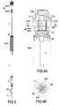
- This block of permanent magnets consists of a coaxial stack of 6c-1 rings ( figure 2 ) comprising neodymium-iron-boron permanent magnet rings, separated by soft iron plate crowns forming an axially perforated permanent magnet block as shown in FIG. figure 2 .
- Said rings 6c-1 are traversed by, and surround coaxially, the main cylindrical wall 5a of the sealed bell 5 and are able to be displaced in vertical translation along and around said cylindrical wall 5a.
- the first synchronous magnetic coupling system 6a comprises a first internal component 6a-2 constituting the "driven” or “induced” part also constituted by a stack of soft iron rings 6c-2 constituting an axially fixed perforated block 6a-2 to and around the upper portion of the bar control rod 3 disposed coaxially in and passing through the axial perforation of said soft iron crown stack block 6a-2.
- the first external component 6a-1 and the first internal component 6a-2 are arranged coaxially at the same height opposite one another on both sides of the cylindrical wall 5a of the sealed bell 5 with a reduced gap and are connected magnetically, so that when the driving portion 6a-1 moves in vertical translation, the driven portion 6a-2 follows this translational movement.
- the first inner component 6a-2 supports the load of the bar control rod 3 and, if appropriate, the control absorber bar 11, an axial shift can be observed in relation to the mass of the load supported according to the stiffness of the coupling.
- the dimensioning of the magnetic coupling is such that this offset remains minimal and in the linear part of the shift curve with respect to the load, and does not modify the rigidity of the coupling, in a manner known in the art. skilled in the art.
- the load is of the order of 300 to 400 kg for the mobile equipment consisting of all the components driven in axial displacement for the handling of the absorbent bar including the rod control rod 3, the gripper 4 and the absorbent control bar 11.All these elements of the mobile equipment are translated to a height of about 1 meter corresponding to the elevation height of the absorbent bar 11 for driving the reactor core.
- the magnet and soft iron ring stacks of the block 6a-1 make it possible to achieve magnetic coupling at a coupling height of about 600 mm sufficient to obtain an offset rigidity of +/- 0.5 mm to +/- 1 mm with a gap of 6 to 7 mm for a non-magnetic wall from 4 to 5 mm and thus from the distances between the wall 5a and the first external component 6a-1 and the first internal component 6a-2 respectively, less than 1 mm.
- first motorized means 2a comprising a first motor 2a-1 cooperating with mechanical transmission elements by contact comprising a gear train 2a-2 comprising two satellite roller screws 2a-3 controlling the displacement in vertical translation of a nut 2a-4 integral with a metal support 8a.
- the two nuts 2a-4 systems of two roller screws 2a-3 are secured to the plate 8a sucker support 8.
- a "satellite roller screw” is a mechanism known to those skilled in the art ensuring the conversion a rotational movement of a screw resulting from the first gear in a translation movement of a nut by threaded helical connection of said screw and said nut.
- the element referred to as the magnetic suction cup 8 generates an attractive force which magnetically links it to the first external component 6a-1, in particular to the upper closure plate 6c ( figures 2 ) of the crown stack 6c-1 of the permanent magnet block of the first external component 6a-1.
- the magnetic suction cup 8 comprises a permanent magnet 8-1 which generates a magnetic flux which guarantees its magnetic bonding with the steel part 6c of the upper end of the first external component 6a-1.
- the magnetic suction cup 8 has the same annular shape with an axial perforation 8c arranged coaxially with said first external component 6a-1 to be arranged around the cylindrical wall 5a of the bell 5 vis-à-vis the upper part 6c in the form of a ring of the first external component 6a-1.
- the magnetic suction cup 8 is a device that allows the automatic emergency shutdown of the reactor by triggering the electrical activation of an electromagnetic coil 8-2 coupled to said permanent magnet 8-1.
- the electromagnetic coil 8-2 associated with the permanent magnet 8-1 has the function of modifying the orientation of the magnetic field produced by the permanent magnet 8-1 as follows.
- the magnetic flux 8-2 'of the electromagnetic coil 8-2 thus generated serves to modify the magnetic flux 8-1' which holds the permanent magnet 8-1 stuck to the metal plate 6c of the upper end of the first outer component 6a-1 which piece 6c is thus subjected to the significant attraction force of the magnet 8-1.
- the magnetic flux generated by the permanent magnet 8-1 adopts a direction 8-1 "which no longer passes through the plate 6c which causes the release of the first external component 6a-1
- spring ejectors can be added between the suction cup 8 and the closure plate 6c. reasons for avoiding sticking by magnetic remanence effect, it is important to position a gap of millimeter between the magnet 8-1 and the plate 6c.
- the magnetic suction cup 8 is therefore in compliance with the requirements of nuclear safety which requires that the automatic shutdown mechanism of the reactor is triggered in case of breakage of the power supply.
- the magnetic block 9-1 of the magnetic damper placed under the first external component 6a-1 of the first system linear coupling is found in coaxial relative displacement with respect to and inside the fixed lower element induced 9-2.
- the relative displacement of the magnetic mass 9-1 with respect to the mass of low electrical resistance 9-2 gives rise, due to the variation of the magnetic flux, in known manner, to Laplace forces which oppose said relative displacement. , the braking efficiency of deceleration of the falling magnetic portion 9-1 being proportional to its coaxial displacement speed relative to the metal part induced 9-2.
- the penetration of the permanent magnet element 9-1 of the magnetic damper in the area of influence of the conductive element 9-2 generates sufficient braking to minimize the impact of the mechanical stop of the lower end of the block; 9-1 magnet against the bottom 5d peripheral flange at the base of the bell 5 and inside the ferrule 9-2.
- the copper ferrule 9-2 extends over a height h3 of about 600 mm.
- the final speed of the mobile equipment before stopping on mechanical stop is about 0.2 m / s.
- the maximum outer diameter of the cylindrical wall 5a of the bell 5 is about 150mm.
- the inner diameter of the 9-2 copper ferrule is about 200-250mm.
- the lower end 6c 'of the first external component 6a-1 arrives just above the upper end of the copper ferrule 9-2 after insertion of the magnetic inductor portion 9-1 into the annular space between the cylindrical wall 5a and the copper ferrule 9-2.
- the second synchronous magnetic coupling system 6b controls the rotation of the guide bar 7 along its longitudinal axis XX 'causing the rotation simultaneous of the rod control rod 3 relative to its longitudinal axis XX 'due to their relative anti-rotation slide connection described above.
- Said second external component 6b-1 is mounted so as to be mechanically drivable in rotation along its axis XX 'because it is integral with a pinion 6-1 driven in rotation by the pinion gear of second gear train 2b-2 powered by a second motor 2b-1.
- the set of second motorized rotation means 2b, 2b-1, 2b-2 are located in the upper compartment 2 outside the sealing bell 5.
- the second rotating coupling system 6b is not part of the mobile equipment in gravity fall during the automatic shutdown of the reactor by deactivation of the magnetic suction cup 8.
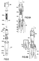
- the gripping device 4 attached to the lower end of the bar control rod 3 is operable in opening and closing for gripping and releasing the upper end 11a of the absorbent control bar 11, by rotation of the control rod 3. This results from the actuation of the second rotating coupling system 6b. More precisely, as shown figure 6 the gripping device 4 comprises a first element 4-1 attached to the lower end of the rod control rod 3 having a male threaded portion 4-1a and a non-threaded lower portion disposed under the thread 4-1a, having a larger diameter portion 4-1b and a lower end portion of smaller diameter 4-1c. The first part 4-1 of the gripper 4 is adapted to cooperate by screwing with a second portion 4-2 having a tapping 4-2a.
- the second part 4-2 supports a plurality of longitudinal fingers 4a regularly distributed around the longitudinal axis XX 'of the rod control rod 3 when the gripper is mounted at its lower end, by screwing the second part 4-2 to thread level 4-1a of the first part 4-1.
- the actuation of the rotation of the rod control rod 3 causes the rotation of the first portion 4-1 of the gripper 4 which allows, in the direction of rotation, to lower or raise the female portion 4-2 whose tapping 4-2a cooperates with the thread 4-1a of the first part 4-1.
- the fingers 4a each comprise a lower end of the lug type formed by an outwardly directed shoulder 4b.
- the flexible fingers 4a are held in the retracted position as close as possible to the region of reduced diameter 4-1c by a lower abutment surface of a lower portion 4c of a third piece 4-3 covering the second piece 4-2 coaxially.
- This part 4-3 comprises a tubular upper part 4-3a, a conical lower part 4c and intermediate longitudinal connecting elements ensuring the connection between parts 4-3a and 4c. Openwork zones 4-3c between the longitudinal elements 4-3b allow the radial expansion of the fingers 4a.
- Two flats positioned, one 4-2b on the part 4-2, the other 4-3d on the part 4-3 serve to block rotation of the 4-2 during translation and thus transform the helical link in slide connection.
- the flexible fingers 4a are held in the retracted position by said abutment surface of the part 4c when the female part 4-2 is positioned in its lowest position relative to the first part 4-1 at the thread 4-1a .
- the relative rotation of the part 4-1 with respect to the part 4-2 in one direction causes the ascent of the part 4-2 towards the upper end of the thread 4-1a, which makes it possible to disengage the lugs 4b retained by the abutment surface 4c and spread in radial expansion relative to each other, the fingers 4a when the lugs 4b meet the enlarged diameter surface 4-1b of the first part 4-1.
- An upper portion 4-4 of the gripping device is integral with the upper end of the upper part of the part 4-3.
- This portion 4-4 has a shape adapted to cooperate with notches at the lower end of the guide sleeve 3a so as to prevent the relative rotation of the part 4-3 with respect to the rod 3.
- a rotation in the opposite direction is effected which has the effect of lowering the piece 4-2 and releasing the lugs 4b of the bearing surface 11b of the control rod 11.
- the rotation of the control rod 3 causing the descent of the part 4-2 is operated until the lugs 4b cooperate again with the surfaces stop 4c of the lower part 4-3 and are held in the retracted position, thus making it possible to disengage the gripper 4 from the upper housing 11a of the control bar 11 by vertical upward translation thereof by means of the first system of synchronous coupling by translation 6a.
- the fingers 4a of the gripper 4 are flexible at the upper part on the outer part 4-2 and the set of lugs 4b at the lower ends of the fingers 4a have an outer surface of conical shape cooperating with a conical complementary surface 4c of the room 4-3.
- the guide sleeve 3a comprises a guide bearing 3c adapted to cooperate with a locking device 3b of the bayonet type device for locking the bar control rod 3 when the latter is in the high position.
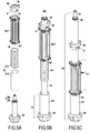
- a translation and rotation of the bar control rod 3 makes it possible to unlock the bar control rod 3 in the up position as shown in FIG. figure 8A then to allow its downward vertical translation to grip an absorbent control bar 11 within its housing 12 shown on the Figure 8B and performing upwardly variable translation of said control absorbent bar 11 to enable and control reactor activity as shown in FIG. Figure 8C .
- the mechanical locking device 3b in the high position by a bayonet system makes it possible to prevent the fall of the bar control rod 3 even in the event of a power failure of the magnetic suction cup 8 and thus makes it possible to dismantle the upper compartment 2 by leaving the bar control rod 3 within the guide sleeve 3a.
- the mechanical locking device in the upper position of the bar control rod comprises, in known manner, locking lugs cooperating with notches in a groove of the bearing 3c inside the guide sleeve when the rod 3 is positioned in rotation from so that the lugs coincide with the said notches.
- a safety ring makes it possible to keep said locked lugs in their notches, said ring cooperating with holding springs and being able to be disengaged by upper translation of the assembly when the device is unlocked.
- a frame 2d constitutes a mechanical structure of the compartment 2 which supports and guides all the elements of the mobile equipment above the closure slab 10 and on which are fixed the sheets forming the wall of the housing 2c of the compartment 2.
- the upper bearing 3c is in an argon atmosphere and supports the locking device in the upper position of the bar control rod 3.
- Attaching the lower flange 5d of the bell 5 to an upper flange of the sleeve 10b or the guide tube 3a is via two O-ring seals.
- the synchronous geared motors 2a-1 and 2b-1 associated with their respective gear train 2a-2 and 2b-2 cooperate with position sensors (not shown) which ensure the control of the translation of the mobile equipment in the area. upper compartment 2 outside the bell 5 and the rotation of the rod control rod.
- position sensors not shown
- These sensors in particular control the positions of the outer part 6a-1 of the first magnetic coupling system 6a in translation between translational travel limit positions as well as the rotational position of the rod rod between limit positions of the clamps 4b of the gripper 4 in retracted position and position of expansion and locking on abutment surfaces 11b of the upper housing 11a of the control absorbent bar 11.
Landscapes
- Physics & Mathematics (AREA)
- Engineering & Computer Science (AREA)
- Plasma & Fusion (AREA)
- General Engineering & Computer Science (AREA)
- High Energy & Nuclear Physics (AREA)
- Chemical & Material Sciences (AREA)
- Chemical Kinetics & Catalysis (AREA)
- Monitoring And Testing Of Nuclear Reactors (AREA)
- Physical Or Chemical Processes And Apparatus (AREA)
- Vibration Prevention Devices (AREA)
- Organic Low-Molecular-Weight Compounds And Preparation Thereof (AREA)
Applications Claiming Priority (1)
| Application Number | Priority Date | Filing Date | Title |
|---|---|---|---|
| FR1553250A FR3035259B1 (fr) | 2015-04-14 | 2015-04-14 | Dispositif de manutention de barre absorbante de controle d'un reacteur nucleaire. |
Publications (2)
| Publication Number | Publication Date |
|---|---|
| EP3082131A1 true EP3082131A1 (de) | 2016-10-19 |
| EP3082131B1 EP3082131B1 (de) | 2017-08-23 |
Family
ID=54329596
Family Applications (1)
| Application Number | Title | Priority Date | Filing Date |
|---|---|---|---|
| EP16164791.2A Active EP3082131B1 (de) | 2015-04-14 | 2016-04-12 | Vorrichtung zur handhabung eines kontrollstabes eines kernreaktors |
Country Status (7)
| Country | Link |
|---|---|
| US (1) | US20160307652A1 (de) |
| EP (1) | EP3082131B1 (de) |
| JP (1) | JP2016206180A (de) |
| KR (1) | KR20160122665A (de) |
| CN (1) | CN106057254B (de) |
| FR (2) | FR3035259B1 (de) |
| RU (1) | RU2016113141A (de) |
Cited By (1)
| Publication number | Priority date | Publication date | Assignee | Title |
|---|---|---|---|---|
| CN119414731A (zh) * | 2024-10-31 | 2025-02-11 | 四川大学 | 控制棒驱动机构多学科仿真调整系统及方法 |
Families Citing this family (13)
| Publication number | Priority date | Publication date | Assignee | Title |
|---|---|---|---|---|
| US10872702B2 (en) * | 2016-07-13 | 2020-12-22 | Ge-Hitachi Nuclear Energy Americas Llc | Stationary isolated rod couplings for use in a nuclear reactor control rod drive |
| RU2637490C1 (ru) * | 2016-10-28 | 2017-12-05 | Акционерное общество "Ордена Трудового Красного Знамени и ордена труда ЧССР опытное конструкторское бюро "ГИДРОПРЕСС" | Устройство электрообогрева ванны для дезактивации |
| CN109378092B (zh) * | 2018-11-12 | 2025-01-10 | 中国原子能科学研究院 | 一种池式低温堆控制棒驱动机构用电磁铁装置 |
| KR20250030525A (ko) * | 2019-02-25 | 2025-03-05 | 웨스팅하우스 일렉트릭 컴퍼니 엘엘씨 | 열 슬리브용 회전 방지 장치 |
| WO2020205106A2 (en) * | 2019-02-28 | 2020-10-08 | Westinghouse Electric Company Llc | Control rod drive mechanism diagnostic tool using voltage and current recordings |
| CN110253480B (zh) * | 2019-06-26 | 2020-12-04 | 中国核动力研究设计院 | 一种控制棒驱动机构焊缝密封装置用安装工具 |
| KR102284601B1 (ko) * | 2019-11-26 | 2021-08-03 | 한국원자력연구원 | 핵연료 고정 장치의 안전 잠금 장치 및 이를 구비하는 핵연료 고정 장치 |
| US20220059247A1 (en) * | 2020-08-18 | 2022-02-24 | Battelle Energy Alliance, Llc | Control rod system for reactor applications |
| GB2593791A (en) * | 2020-12-03 | 2021-10-06 | Rolls Royce Plc | Integrated head package |
| CN115132386B (zh) * | 2022-06-27 | 2025-08-01 | 中国科学院力学研究所 | 一种反应堆控制棒偏心落棒实验装置及模拟方法 |
| CN115274145B (zh) * | 2022-07-29 | 2025-12-26 | 中科超安科技有限公司 | 用于反应堆的并行传动控制棒驱动机构 |
| KR102830651B1 (ko) * | 2023-01-04 | 2025-07-08 | 한국수력원자력 주식회사 | 원자로의 수직 반응도 제어기구의 해체방법 및 장치 |
| CN118098650A (zh) * | 2024-01-16 | 2024-05-28 | 中国核电工程有限公司 | 一种核反应堆控制棒驱动系统 |
Citations (7)
| Publication number | Priority date | Publication date | Assignee | Title |
|---|---|---|---|---|
| US2837477A (en) * | 1945-02-16 | 1958-06-03 | Fermi Enrico | Chain reacting system |
| FR2455336A1 (fr) * | 1979-04-27 | 1980-11-21 | Jeumont Schneider | Dispositif electromagnetique de commande de barre dans un reacteur nucleaire |
| US4487739A (en) * | 1979-11-21 | 1984-12-11 | United Kingdom Atomic Energy Authority | Hydraulic shock absorbers |
| US4618471A (en) * | 1980-01-24 | 1986-10-21 | Jeumont-Schneider | Electromagnetic safety device of a screw/nut type |
| JP2006145233A (ja) * | 2004-11-16 | 2006-06-08 | Toshiba Corp | 上部設置型制御棒駆動装置 |
| WO2007055645A1 (en) * | 2005-11-09 | 2007-05-18 | Westinghouse Electric Sweden Ab | A control device and a nuclear reactor plant |
| FR2995437A1 (fr) * | 2012-09-07 | 2014-03-14 | Commissariat Energie Atomique | Dispositif de controle nucleaire pour reacteur refroidi au metal liquide de type rnr. |
Family Cites Families (11)
| Publication number | Priority date | Publication date | Assignee | Title |
|---|---|---|---|---|
| JPS51116393A (en) * | 1975-04-04 | 1976-10-13 | Hitachi Ltd | A control rod driving mechanism |
| JPS5371791A (en) * | 1976-12-06 | 1978-06-26 | Nippon Kokan Kk <Nkk> | Control rod driving device for movalbe magnet coil type |
| JPS5948689A (ja) * | 1982-09-14 | 1984-03-19 | 財団法人電力中央研究所 | 原子炉制御装置 |
| JPS5968295U (ja) * | 1982-10-30 | 1984-05-09 | 三井造船株式会社 | 制御棒駆動装置 |
| JPS6176985A (ja) * | 1984-09-21 | 1986-04-19 | 株式会社東芝 | 制御棒駆動機構 |
| JPH04370796A (ja) * | 1991-06-19 | 1992-12-24 | Nkk Corp | 可動コイル式磁気駆動装置 |
| JPH06235786A (ja) * | 1993-02-10 | 1994-08-23 | Toshiba Corp | 原子炉停止装置 |
| US5517536A (en) * | 1994-08-24 | 1996-05-14 | General Electric Company | Magnetic coupling device for control rod drive |
| US9877139B2 (en) * | 2011-10-03 | 2018-01-23 | Intel Corporation | Device to device (D2D) communication mechanisms |
| CN104183280B (zh) * | 2014-08-25 | 2017-07-14 | 中广核研究院有限公司 | 控制棒驱动机构及其与控制棒的连接方式 |
| US9849480B2 (en) * | 2014-11-26 | 2017-12-26 | Illinois Tool Works Inc. | Laminated nozzle with thick plate |
-
2015
- 2015-04-14 FR FR1553250A patent/FR3035259B1/fr not_active Expired - Fee Related
- 2015-06-03 FR FR1555062A patent/FR3035260B1/fr active Active
-
2016
- 2016-04-07 RU RU2016113141A patent/RU2016113141A/ru not_active Application Discontinuation
- 2016-04-12 CN CN201610224859.XA patent/CN106057254B/zh not_active Expired - Fee Related
- 2016-04-12 EP EP16164791.2A patent/EP3082131B1/de active Active
- 2016-04-12 JP JP2016079817A patent/JP2016206180A/ja active Pending
- 2016-04-14 KR KR1020160045647A patent/KR20160122665A/ko not_active Withdrawn
- 2016-04-14 US US15/098,333 patent/US20160307652A1/en not_active Abandoned
Patent Citations (7)
| Publication number | Priority date | Publication date | Assignee | Title |
|---|---|---|---|---|
| US2837477A (en) * | 1945-02-16 | 1958-06-03 | Fermi Enrico | Chain reacting system |
| FR2455336A1 (fr) * | 1979-04-27 | 1980-11-21 | Jeumont Schneider | Dispositif electromagnetique de commande de barre dans un reacteur nucleaire |
| US4487739A (en) * | 1979-11-21 | 1984-12-11 | United Kingdom Atomic Energy Authority | Hydraulic shock absorbers |
| US4618471A (en) * | 1980-01-24 | 1986-10-21 | Jeumont-Schneider | Electromagnetic safety device of a screw/nut type |
| JP2006145233A (ja) * | 2004-11-16 | 2006-06-08 | Toshiba Corp | 上部設置型制御棒駆動装置 |
| WO2007055645A1 (en) * | 2005-11-09 | 2007-05-18 | Westinghouse Electric Sweden Ab | A control device and a nuclear reactor plant |
| FR2995437A1 (fr) * | 2012-09-07 | 2014-03-14 | Commissariat Energie Atomique | Dispositif de controle nucleaire pour reacteur refroidi au metal liquide de type rnr. |
Cited By (1)
| Publication number | Priority date | Publication date | Assignee | Title |
|---|---|---|---|---|
| CN119414731A (zh) * | 2024-10-31 | 2025-02-11 | 四川大学 | 控制棒驱动机构多学科仿真调整系统及方法 |
Also Published As
| Publication number | Publication date |
|---|---|
| JP2016206180A (ja) | 2016-12-08 |
| FR3035260B1 (fr) | 2017-05-05 |
| KR20160122665A (ko) | 2016-10-24 |
| CN106057254B (zh) | 2018-05-01 |
| FR3035260A1 (fr) | 2016-10-21 |
| RU2016113141A (ru) | 2017-10-10 |
| RU2016113141A3 (de) | 2019-09-09 |
| EP3082131B1 (de) | 2017-08-23 |
| FR3035259B1 (fr) | 2017-04-28 |
| FR3035259A1 (fr) | 2016-10-21 |
| CN106057254A (zh) | 2016-10-26 |
| US20160307652A1 (en) | 2016-10-20 |
Similar Documents
| Publication | Publication Date | Title |
|---|---|---|
| EP3082131B1 (de) | Vorrichtung zur handhabung eines kontrollstabes eines kernreaktors | |
| JP6023042B2 (ja) | 原子炉用制御棒駆動機構及び装置 | |
| EP0111435B1 (de) | Steuervorrichtung zweier Regelstabbündel die im gleichen Brennelementbündel des Kernes eines Kernreaktors senkrecht verschiebbar sind | |
| CA2729320C (fr) | Dispositif de mesure de grandeurs physiques de matieres nucleaires et procede de mise en oeuvre d'un tel dispositif | |
| FR2983625A1 (fr) | Dispositif de declenchement et d'insertion d'elements absorbants et/ou mitigateurs dans une zone fissile d'un reacteur nucleaire et assemblage de combustible nucleaire comportant un tel dispositif | |
| EP2887358A1 (de) | Ventilklappe für Flüssigkeitskreislauf | |
| CA2993491A1 (fr) | Reacteur nucleaire avec entrainement des organes de controle de la reactivite du coeur de type vis-ecrou | |
| FR2682803A1 (fr) | Procede et dispositif pour prelever une eprouvette dans la cuve d'un reacteur nucleaire en arret definitif. | |
| WO2011033220A1 (fr) | Dispositif d'aide sous eau à l'extraction ou à l'insertion d'un élément de forme allongée disposé dans un conduit et procédé d'aide à l'extraction ou à l'insertion d'un tel élément | |
| FR2848717A1 (fr) | Procede et dispositif de manutention d'un tube-guide des equipements internes superieurs d'un reacteur nucleaire | |
| FR2461334A1 (fr) | Mecanisme a pignon et cremaillere pour le deplacement d'un ensemble absorbant les neutrons dans un reacteur nucleaire | |
| EP0026142B1 (de) | Ferngesteuerte Kupplungs- und Entkupplungsvorrichtung für zwei Elemente grosser Länge, die koaxial zueinander ausgerichtet sind und sich mit ihren Stirnflächen berühren | |
| EP2789550B1 (de) | Handhabungs- und Begrenzungshaube, Anwendung zur Handhabung von Probengefäßen für nukleares Material, insbesondere Kernbrennstoffe | |
| FR2459535A1 (fr) | Mecanisme a doigts a mouvement cyclique pour la commande d'un reacteur nucleaire | |
| FR3070020B1 (fr) | Outil de soudage de goujon sous eau | |
| EP3750170B1 (de) | Integrierte kernreaktorarchitektur zur begrenzung der belastung der integrierten mechanismen | |
| EP0312418A1 (de) | Fernbedienbares Werkzeug zum Setzen und Entfernen eines Pfropfens in einem Dampferzeugerrohr | |
| FR3044155A1 (fr) | Dispositif de surete a declenchement passif pour reacteur nucleaire sur une baisse anormale du debit primaire | |
| CA1160366A (fr) | Mecanisme a vis et ecrou pour la commande d'un reacteur nucleaire | |
| FR2728098A1 (fr) | Dispositif de liaison anti-ejection entre un ensemble absorbant de reacteur nucleaire et une tige de commande de cet ensemble | |
| WO2020020641A1 (fr) | Dispositif de manutention pour assemblage combustible et ensemble de manutention comprenant un tel dispositif | |
| FR2583205A1 (fr) | Machine pour demonter des reacteurs nucleaires declasses ou leurs composants | |
| FR2734638A1 (fr) | Dispositif de neutronographie | |
| FR2472248A1 (fr) | Dispositif de commande d'un reacteur nucleaire par deplacement vertical d'un ensemble absorbant les neutrons | |
| FR3053517A1 (fr) | Systeme de verrouillage mecanique du mecanisme hydraulique de deplacement des barres de controle d'un reacteur nucleaire, de type smr |
Legal Events
| Date | Code | Title | Description |
|---|---|---|---|
| PUAI | Public reference made under article 153(3) epc to a published international application that has entered the european phase |
Free format text: ORIGINAL CODE: 0009012 |
|
| AK | Designated contracting states |
Kind code of ref document: A1 Designated state(s): AL AT BE BG CH CY CZ DE DK EE ES FI FR GB GR HR HU IE IS IT LI LT LU LV MC MK MT NL NO PL PT RO RS SE SI SK SM TR |
|
| AX | Request for extension of the european patent |
Extension state: BA ME |
|
| STAA | Information on the status of an ep patent application or granted ep patent |
Free format text: STATUS: REQUEST FOR EXAMINATION WAS MADE |
|
| 17P | Request for examination filed |
Effective date: 20170125 |
|
| RBV | Designated contracting states (corrected) |
Designated state(s): AL AT BE BG CH CY CZ DE DK EE ES FI FR GB GR HR HU IE IS IT LI LT LU LV MC MK MT NL NO PL PT RO RS SE SI SK SM TR |
|
| GRAP | Despatch of communication of intention to grant a patent |
Free format text: ORIGINAL CODE: EPIDOSNIGR1 |
|
| STAA | Information on the status of an ep patent application or granted ep patent |
Free format text: STATUS: GRANT OF PATENT IS INTENDED |
|
| RIC1 | Information provided on ipc code assigned before grant |
Ipc: G21C 7/14 20060101AFI20170404BHEP Ipc: G21C 1/03 20060101ALN20170404BHEP Ipc: G21C 7/08 20060101ALN20170404BHEP Ipc: G21C 7/20 20060101ALI20170404BHEP |
|
| INTG | Intention to grant announced |
Effective date: 20170502 |
|
| GRAS | Grant fee paid |
Free format text: ORIGINAL CODE: EPIDOSNIGR3 |
|
| GRAA | (expected) grant |
Free format text: ORIGINAL CODE: 0009210 |
|
| STAA | Information on the status of an ep patent application or granted ep patent |
Free format text: STATUS: THE PATENT HAS BEEN GRANTED |
|
| AK | Designated contracting states |
Kind code of ref document: B1 Designated state(s): AL AT BE BG CH CY CZ DE DK EE ES FI FR GB GR HR HU IE IS IT LI LT LU LV MC MK MT NL NO PL PT RO RS SE SI SK SM TR |
|
| REG | Reference to a national code |
Ref country code: GB Ref legal event code: FG4D Free format text: NOT ENGLISH |
|
| REG | Reference to a national code |
Ref country code: CH Ref legal event code: EP |
|
| REG | Reference to a national code |
Ref country code: AT Ref legal event code: REF Ref document number: 922147 Country of ref document: AT Kind code of ref document: T Effective date: 20170915 |
|
| REG | Reference to a national code |
Ref country code: IE Ref legal event code: FG4D Free format text: LANGUAGE OF EP DOCUMENT: FRENCH |
|
| REG | Reference to a national code |
Ref country code: DE Ref legal event code: R096 Ref document number: 602016000274 Country of ref document: DE |
|
| REG | Reference to a national code |
Ref country code: DE Ref legal event code: R081 Ref document number: 602016000274 Country of ref document: DE Owner name: COMMISSARIAT A L'ENERGIE ATOMIQUE ET AUX ENERG, FR Free format text: FORMER OWNERS: COMEX NUCLEAIRE, MARSEILLE, FR; COMMISSARIAT A L'ENERGIE ATOMIQUE ET AUX ENERGIES ALTERNATIVES, PARIS, FR Ref country code: DE Ref legal event code: R081 Ref document number: 602016000274 Country of ref document: DE Owner name: ONET TECHNOLOGIES CN, FR Free format text: FORMER OWNERS: COMEX NUCLEAIRE, MARSEILLE, FR; COMMISSARIAT A L'ENERGIE ATOMIQUE ET AUX ENERGIES ALTERNATIVES, PARIS, FR |
|
| RAP2 | Party data changed (patent owner data changed or rights of a patent transferred) |
Owner name: ONET TECHNOLOGIES CN Owner name: COMMISSARIAT A L'ENERGIE ATOMIQUE ET AUX ENERGIES |
|
| REG | Reference to a national code |
Ref country code: NL Ref legal event code: MP Effective date: 20170823 |
|
| REG | Reference to a national code |
Ref country code: LT Ref legal event code: MG4D |
|
| REG | Reference to a national code |
Ref country code: AT Ref legal event code: MK05 Ref document number: 922147 Country of ref document: AT Kind code of ref document: T Effective date: 20170823 |
|
| PG25 | Lapsed in a contracting state [announced via postgrant information from national office to epo] |
Ref country code: AT Free format text: LAPSE BECAUSE OF FAILURE TO SUBMIT A TRANSLATION OF THE DESCRIPTION OR TO PAY THE FEE WITHIN THE PRESCRIBED TIME-LIMIT Effective date: 20170823 Ref country code: NL Free format text: LAPSE BECAUSE OF FAILURE TO SUBMIT A TRANSLATION OF THE DESCRIPTION OR TO PAY THE FEE WITHIN THE PRESCRIBED TIME-LIMIT Effective date: 20170823 Ref country code: LT Free format text: LAPSE BECAUSE OF FAILURE TO SUBMIT A TRANSLATION OF THE DESCRIPTION OR TO PAY THE FEE WITHIN THE PRESCRIBED TIME-LIMIT Effective date: 20170823 Ref country code: SE Free format text: LAPSE BECAUSE OF FAILURE TO SUBMIT A TRANSLATION OF THE DESCRIPTION OR TO PAY THE FEE WITHIN THE PRESCRIBED TIME-LIMIT Effective date: 20170823 Ref country code: FI Free format text: LAPSE BECAUSE OF FAILURE TO SUBMIT A TRANSLATION OF THE DESCRIPTION OR TO PAY THE FEE WITHIN THE PRESCRIBED TIME-LIMIT Effective date: 20170823 Ref country code: NO Free format text: LAPSE BECAUSE OF FAILURE TO SUBMIT A TRANSLATION OF THE DESCRIPTION OR TO PAY THE FEE WITHIN THE PRESCRIBED TIME-LIMIT Effective date: 20171123 Ref country code: HR Free format text: LAPSE BECAUSE OF FAILURE TO SUBMIT A TRANSLATION OF THE DESCRIPTION OR TO PAY THE FEE WITHIN THE PRESCRIBED TIME-LIMIT Effective date: 20170823 |
|
| PG25 | Lapsed in a contracting state [announced via postgrant information from national office to epo] |
Ref country code: IS Free format text: LAPSE BECAUSE OF FAILURE TO SUBMIT A TRANSLATION OF THE DESCRIPTION OR TO PAY THE FEE WITHIN THE PRESCRIBED TIME-LIMIT Effective date: 20171223 Ref country code: LV Free format text: LAPSE BECAUSE OF FAILURE TO SUBMIT A TRANSLATION OF THE DESCRIPTION OR TO PAY THE FEE WITHIN THE PRESCRIBED TIME-LIMIT Effective date: 20170823 Ref country code: GR Free format text: LAPSE BECAUSE OF FAILURE TO SUBMIT A TRANSLATION OF THE DESCRIPTION OR TO PAY THE FEE WITHIN THE PRESCRIBED TIME-LIMIT Effective date: 20171124 Ref country code: ES Free format text: LAPSE BECAUSE OF FAILURE TO SUBMIT A TRANSLATION OF THE DESCRIPTION OR TO PAY THE FEE WITHIN THE PRESCRIBED TIME-LIMIT Effective date: 20170823 Ref country code: RS Free format text: LAPSE BECAUSE OF FAILURE TO SUBMIT A TRANSLATION OF THE DESCRIPTION OR TO PAY THE FEE WITHIN THE PRESCRIBED TIME-LIMIT Effective date: 20170823 Ref country code: PL Free format text: LAPSE BECAUSE OF FAILURE TO SUBMIT A TRANSLATION OF THE DESCRIPTION OR TO PAY THE FEE WITHIN THE PRESCRIBED TIME-LIMIT Effective date: 20170823 Ref country code: BG Free format text: LAPSE BECAUSE OF FAILURE TO SUBMIT A TRANSLATION OF THE DESCRIPTION OR TO PAY THE FEE WITHIN THE PRESCRIBED TIME-LIMIT Effective date: 20171123 |
|
| REG | Reference to a national code |
Ref country code: FR Ref legal event code: PLFP Year of fee payment: 3 |
|
| PG25 | Lapsed in a contracting state [announced via postgrant information from national office to epo] |
Ref country code: DK Free format text: LAPSE BECAUSE OF FAILURE TO SUBMIT A TRANSLATION OF THE DESCRIPTION OR TO PAY THE FEE WITHIN THE PRESCRIBED TIME-LIMIT Effective date: 20170823 Ref country code: CZ Free format text: LAPSE BECAUSE OF FAILURE TO SUBMIT A TRANSLATION OF THE DESCRIPTION OR TO PAY THE FEE WITHIN THE PRESCRIBED TIME-LIMIT Effective date: 20170823 |
|
| REG | Reference to a national code |
Ref country code: DE Ref legal event code: R097 Ref document number: 602016000274 Country of ref document: DE |
|
| PG25 | Lapsed in a contracting state [announced via postgrant information from national office to epo] |
Ref country code: SK Free format text: LAPSE BECAUSE OF FAILURE TO SUBMIT A TRANSLATION OF THE DESCRIPTION OR TO PAY THE FEE WITHIN THE PRESCRIBED TIME-LIMIT Effective date: 20170823 Ref country code: IT Free format text: LAPSE BECAUSE OF FAILURE TO SUBMIT A TRANSLATION OF THE DESCRIPTION OR TO PAY THE FEE WITHIN THE PRESCRIBED TIME-LIMIT Effective date: 20170823 Ref country code: SM Free format text: LAPSE BECAUSE OF FAILURE TO SUBMIT A TRANSLATION OF THE DESCRIPTION OR TO PAY THE FEE WITHIN THE PRESCRIBED TIME-LIMIT Effective date: 20170823 Ref country code: EE Free format text: LAPSE BECAUSE OF FAILURE TO SUBMIT A TRANSLATION OF THE DESCRIPTION OR TO PAY THE FEE WITHIN THE PRESCRIBED TIME-LIMIT Effective date: 20170823 |
|
| PLBE | No opposition filed within time limit |
Free format text: ORIGINAL CODE: 0009261 |
|
| STAA | Information on the status of an ep patent application or granted ep patent |
Free format text: STATUS: NO OPPOSITION FILED WITHIN TIME LIMIT |
|
| 26N | No opposition filed |
Effective date: 20180524 |
|
| PG25 | Lapsed in a contracting state [announced via postgrant information from national office to epo] |
Ref country code: SI Free format text: LAPSE BECAUSE OF FAILURE TO SUBMIT A TRANSLATION OF THE DESCRIPTION OR TO PAY THE FEE WITHIN THE PRESCRIBED TIME-LIMIT Effective date: 20170823 |
|
| PG25 | Lapsed in a contracting state [announced via postgrant information from national office to epo] |
Ref country code: MT Free format text: LAPSE BECAUSE OF FAILURE TO SUBMIT A TRANSLATION OF THE DESCRIPTION OR TO PAY THE FEE WITHIN THE PRESCRIBED TIME-LIMIT Effective date: 20170823 |
|
| PG25 | Lapsed in a contracting state [announced via postgrant information from national office to epo] |
Ref country code: MC Free format text: LAPSE BECAUSE OF FAILURE TO SUBMIT A TRANSLATION OF THE DESCRIPTION OR TO PAY THE FEE WITHIN THE PRESCRIBED TIME-LIMIT Effective date: 20170823 |
|
| REG | Reference to a national code |
Ref country code: BE Ref legal event code: MM Effective date: 20180430 |
|
| REG | Reference to a national code |
Ref country code: IE Ref legal event code: MM4A |
|
| PG25 | Lapsed in a contracting state [announced via postgrant information from national office to epo] |
Ref country code: LU Free format text: LAPSE BECAUSE OF NON-PAYMENT OF DUE FEES Effective date: 20180412 |
|
| PG25 | Lapsed in a contracting state [announced via postgrant information from national office to epo] |
Ref country code: BE Free format text: LAPSE BECAUSE OF NON-PAYMENT OF DUE FEES Effective date: 20180430 |
|
| PG25 | Lapsed in a contracting state [announced via postgrant information from national office to epo] |
Ref country code: IE Free format text: LAPSE BECAUSE OF NON-PAYMENT OF DUE FEES Effective date: 20180412 |
|
| PGFP | Annual fee paid to national office [announced via postgrant information from national office to epo] |
Ref country code: DE Payment date: 20190415 Year of fee payment: 4 |
|
| REG | Reference to a national code |
Ref country code: CH Ref legal event code: PL |
|
| PG25 | Lapsed in a contracting state [announced via postgrant information from national office to epo] |
Ref country code: CH Free format text: LAPSE BECAUSE OF NON-PAYMENT OF DUE FEES Effective date: 20190430 Ref country code: LI Free format text: LAPSE BECAUSE OF NON-PAYMENT OF DUE FEES Effective date: 20190430 |
|
| PG25 | Lapsed in a contracting state [announced via postgrant information from national office to epo] |
Ref country code: TR Free format text: LAPSE BECAUSE OF FAILURE TO SUBMIT A TRANSLATION OF THE DESCRIPTION OR TO PAY THE FEE WITHIN THE PRESCRIBED TIME-LIMIT Effective date: 20170823 |
|
| PG25 | Lapsed in a contracting state [announced via postgrant information from national office to epo] |
Ref country code: PT Free format text: LAPSE BECAUSE OF FAILURE TO SUBMIT A TRANSLATION OF THE DESCRIPTION OR TO PAY THE FEE WITHIN THE PRESCRIBED TIME-LIMIT Effective date: 20170823 |
|
| PG25 | Lapsed in a contracting state [announced via postgrant information from national office to epo] |
Ref country code: HU Free format text: LAPSE BECAUSE OF FAILURE TO SUBMIT A TRANSLATION OF THE DESCRIPTION OR TO PAY THE FEE WITHIN THE PRESCRIBED TIME-LIMIT; INVALID AB INITIO Effective date: 20160412 Ref country code: CY Free format text: LAPSE BECAUSE OF FAILURE TO SUBMIT A TRANSLATION OF THE DESCRIPTION OR TO PAY THE FEE WITHIN THE PRESCRIBED TIME-LIMIT Effective date: 20170823 Ref country code: RO Free format text: LAPSE BECAUSE OF FAILURE TO SUBMIT A TRANSLATION OF THE DESCRIPTION OR TO PAY THE FEE WITHIN THE PRESCRIBED TIME-LIMIT Effective date: 20170823 Ref country code: MK Free format text: LAPSE BECAUSE OF NON-PAYMENT OF DUE FEES Effective date: 20170823 |
|
| PG25 | Lapsed in a contracting state [announced via postgrant information from national office to epo] |
Ref country code: AL Free format text: LAPSE BECAUSE OF FAILURE TO SUBMIT A TRANSLATION OF THE DESCRIPTION OR TO PAY THE FEE WITHIN THE PRESCRIBED TIME-LIMIT Effective date: 20170823 |
|
| REG | Reference to a national code |
Ref country code: DE Ref legal event code: R119 Ref document number: 602016000274 Country of ref document: DE |
|
| PG25 | Lapsed in a contracting state [announced via postgrant information from national office to epo] |
Ref country code: DE Free format text: LAPSE BECAUSE OF NON-PAYMENT OF DUE FEES Effective date: 20201103 |
|
| GBPC | Gb: european patent ceased through non-payment of renewal fee |
Effective date: 20200412 |
|
| PG25 | Lapsed in a contracting state [announced via postgrant information from national office to epo] |
Ref country code: GB Free format text: LAPSE BECAUSE OF NON-PAYMENT OF DUE FEES Effective date: 20200412 |
|
| PGFP | Annual fee paid to national office [announced via postgrant information from national office to epo] |
Ref country code: FR Payment date: 20250422 Year of fee payment: 10 |