EP3082210B1 - Stromerzeugungssystem und verfahren mit energiemanagement - Google Patents
Stromerzeugungssystem und verfahren mit energiemanagement Download PDFInfo
- Publication number
- EP3082210B1 EP3082210B1 EP16163936.4A EP16163936A EP3082210B1 EP 3082210 B1 EP3082210 B1 EP 3082210B1 EP 16163936 A EP16163936 A EP 16163936A EP 3082210 B1 EP3082210 B1 EP 3082210B1
- Authority
- EP
- European Patent Office
- Prior art keywords
- power
- bus
- voltage
- controller
- threshold
- Prior art date
- Legal status (The legal status is an assumption and is not a legal conclusion. Google has not performed a legal analysis and makes no representation as to the accuracy of the status listed.)
- Not-in-force
Links
Images





Classifications
-
- H—ELECTRICITY
- H02—GENERATION; CONVERSION OR DISTRIBUTION OF ELECTRIC POWER
- H02J—ELECTRIC POWER NETWORKS; CIRCUIT ARRANGEMENTS OR SYSTEMS FOR SUPPLYING OR DISTRIBUTING ELECTRIC POWER; SYSTEMS FOR STORING ELECTRIC ENERGY
- H02J3/00—Circuit arrangements for AC mains or AC distribution networks
- H02J3/38—Arrangements for feeding a single network from two or more generators or sources in parallel; Arrangements for feeding already energised networks from additional generators or sources in parallel
- H02J3/381—Dispersed generators
-
- H—ELECTRICITY
- H02—GENERATION; CONVERSION OR DISTRIBUTION OF ELECTRIC POWER
- H02J—ELECTRIC POWER NETWORKS; CIRCUIT ARRANGEMENTS OR SYSTEMS FOR SUPPLYING OR DISTRIBUTING ELECTRIC POWER; SYSTEMS FOR STORING ELECTRIC ENERGY
- H02J1/00—Circuit arrangements for DC mains or DC distribution networks
- H02J1/10—Parallel operation of DC sources
- H02J1/12—Parallel operation of DC sources having power converters with further DC sources without power converters
-
- H—ELECTRICITY
- H02—GENERATION; CONVERSION OR DISTRIBUTION OF ELECTRIC POWER
- H02J—ELECTRIC POWER NETWORKS; CIRCUIT ARRANGEMENTS OR SYSTEMS FOR SUPPLYING OR DISTRIBUTING ELECTRIC POWER; SYSTEMS FOR STORING ELECTRIC ENERGY
- H02J7/00—Circuit arrangements for charging or discharging batteries or for supplying loads from batteries
- H02J7/34—Parallel operation in networks using both storage and other DC sources, e.g. providing buffering
- H02J7/345—Parallel operation in networks using both storage and other DC sources, e.g. providing buffering using capacitors as storage or buffering devices
-
- H—ELECTRICITY
- H02—GENERATION; CONVERSION OR DISTRIBUTION OF ELECTRIC POWER
- H02J—ELECTRIC POWER NETWORKS; CIRCUIT ARRANGEMENTS OR SYSTEMS FOR SUPPLYING OR DISTRIBUTING ELECTRIC POWER; SYSTEMS FOR STORING ELECTRIC ENERGY
- H02J7/00—Circuit arrangements for charging or discharging batteries or for supplying loads from batteries
- H02J7/865—Battery or charger load switching, e.g. concurrent charging and load supply
-
- H—ELECTRICITY
- H02—GENERATION; CONVERSION OR DISTRIBUTION OF ELECTRIC POWER
- H02M—APPARATUS FOR CONVERSION BETWEEN AC AND AC, BETWEEN AC AND DC, OR BETWEEN DC AND DC, AND FOR USE WITH MAINS OR SIMILAR POWER SUPPLY SYSTEMS; CONVERSION OF DC OR AC INPUT POWER INTO SURGE OUTPUT POWER; CONTROL OR REGULATION THEREOF
- H02M3/00—Conversion of DC power input into DC power output
- H02M3/02—Conversion of DC power input into DC power output without intermediate conversion into AC
- H02M3/04—Conversion of DC power input into DC power output without intermediate conversion into AC by static converters
-
- H—ELECTRICITY
- H02—GENERATION; CONVERSION OR DISTRIBUTION OF ELECTRIC POWER
- H02M—APPARATUS FOR CONVERSION BETWEEN AC AND AC, BETWEEN AC AND DC, OR BETWEEN DC AND DC, AND FOR USE WITH MAINS OR SIMILAR POWER SUPPLY SYSTEMS; CONVERSION OF DC OR AC INPUT POWER INTO SURGE OUTPUT POWER; CONTROL OR REGULATION THEREOF
- H02M7/00—Conversion of AC power input into DC power output; Conversion of DC power input into AC power output
- H02M7/02—Conversion of AC power input into DC power output without possibility of reversal
- H02M7/04—Conversion of AC power input into DC power output without possibility of reversal by static converters
-
- H—ELECTRICITY
- H02—GENERATION; CONVERSION OR DISTRIBUTION OF ELECTRIC POWER
- H02M—APPARATUS FOR CONVERSION BETWEEN AC AND AC, BETWEEN AC AND DC, OR BETWEEN DC AND DC, AND FOR USE WITH MAINS OR SIMILAR POWER SUPPLY SYSTEMS; CONVERSION OF DC OR AC INPUT POWER INTO SURGE OUTPUT POWER; CONTROL OR REGULATION THEREOF
- H02M7/00—Conversion of AC power input into DC power output; Conversion of DC power input into AC power output
- H02M7/42—Conversion of DC power input into AC power output without possibility of reversal
- H02M7/44—Conversion of DC power input into AC power output without possibility of reversal by static converters
-
- H—ELECTRICITY
- H02—GENERATION; CONVERSION OR DISTRIBUTION OF ELECTRIC POWER
- H02J—ELECTRIC POWER NETWORKS; CIRCUIT ARRANGEMENTS OR SYSTEMS FOR SUPPLYING OR DISTRIBUTING ELECTRIC POWER; SYSTEMS FOR STORING ELECTRIC ENERGY
- H02J2101/00—Supply or distribution of decentralised, dispersed or local electric power generation
- H02J2101/20—Dispersed power generation using renewable energy sources
- H02J2101/28—Wind energy
-
- Y—GENERAL TAGGING OF NEW TECHNOLOGICAL DEVELOPMENTS; GENERAL TAGGING OF CROSS-SECTIONAL TECHNOLOGIES SPANNING OVER SEVERAL SECTIONS OF THE IPC; TECHNICAL SUBJECTS COVERED BY FORMER USPC CROSS-REFERENCE ART COLLECTIONS [XRACs] AND DIGESTS
- Y02—TECHNOLOGIES OR APPLICATIONS FOR MITIGATION OR ADAPTATION AGAINST CLIMATE CHANGE
- Y02E—REDUCTION OF GREENHOUSE GAS [GHG] EMISSIONS, RELATED TO ENERGY GENERATION, TRANSMISSION OR DISTRIBUTION
- Y02E10/00—Energy generation through renewable energy sources
- Y02E10/70—Wind energy
- Y02E10/76—Power conversion electric or electronic aspects
Definitions
- the wind turbine housing 21 is configured to enclose the AC generator 22, the power converter 24, the ES 26, PS 27, and the wind turbine controller 28 therein.
- the wind turbine 20 is rotatably coupled to the wind turbine housing 21.
- the power converter 24 is configured to receive the AC voltage from the AC generator 22 and to supply an AC voltage to the AC electrical grid 12.
- the power converter 24 is further configured to supply a DC voltage to the ES 26 and/or the PS 27 for storing excess electrical energy generated by the AC generator 22, or configured to obtain the DC voltage from the ES 26 and/or the PS 27.
- the power converter 24 includes a housing 39, a rectifier 40, an inverter 42, a first DC-DC converter 44, a second DC-DC converter 45, a power converter controller 46, and a discharge-charge controller 48.
- the housing 39 is configured to hold the rectifier 40, the inverter 42, the first DC-DC converter 44, the second DC-DC converter 45, the controller 46, the discharge-charge controller 48 therein.
- the inverter 42 is configured to receive the DC voltage from the DC voltage bus 41 and to convert the DC voltage to an AC voltage that is output from the inverter 42 to the AC electrical grid 12.
- the inverter 42 outputs the AC voltage to the AC electrical grid 12 in response to the inverter 42 receiving a control signal from the power converter controller 46.
- the power converter controller 46 generates the control signal that is received by the inverter 42, in response to the power converter controller 46 receiving a control signal from the wind farm controller 30.
- the first DC-DC converter 44 is configured to receive the DC voltage from the DC voltage bus 41.
- the first DC-DC converter 44 adjusts the voltage level of the DC voltage and outputs a DC voltage to the ES 26 in response to a control signal from the discharge-charge controller 48.
- the ES 26 receives the DC voltage output from the first DC-DC converter 44 and stores electrical energy therein.
- the first DC-DC converter 44 is further configured to output a DC voltage on the DC voltage bus 41 utilizing electrical energy from the ES 26 in response to another control signal from the discharge-charge controller 48.
- the second DC-DC converter 45 is configured to receive the DC voltage from the DC voltage bus 41.
- V PS V max • f V forecast
- the net power is supplied to both the ES 26 and the PS 27.
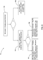
- the part of the net power supplied to the ES 26 is substantially equal to the charging power threshold and the rest of the net power is supplied to the PS 27 when the power supplied to the PS 27 is less than a maximum PS charging power thereof.
- the maximum PS charging power represents a maximum power which the PS 27 can be charged, which is determined according to the capacity of the PS 27.
- the power supplied to the ES 26 rises slightly with the net power rising, and the rest of the net power is supplied to the PS 27. Accordingly, the PS 27 handles the quick increment of the net power since the PS 27 is charged fast.
- the charging power threshold and the discharging power threshold are determined according to lifetime of the ES 26 and abilities of the PS 27 on charging and discharging, in order to protect the ES 26, extend life of the ES 26, and rational use the capacity of the PS 27.
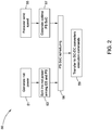
- the ES 26 provides or receives a smooth power and the PS 27 can handle the fast changing power.
- the ES 26 in the condition that the net power is not less than the discharging power threshold, the ES 26 provides the power being equal to the absolute value of the net power.
- the ES initial power command is equal to the net power and the PS initial power command is zero.
- the ES 26 provides extra power to charge the PS 27 when the voltage of the PS 27 is lower than the lower limit.
- the ES initial power command and the PS initial power command are adjusted based on the extra power from the ES 26 to the PS 27 to generate the ES power command and the PS power command.
Landscapes
- Engineering & Computer Science (AREA)
- Power Engineering (AREA)
- Supply And Distribution Of Alternating Current (AREA)
- Charge And Discharge Circuits For Batteries Or The Like (AREA)
Claims (15)
- System (10), umfassend:einen Bus (41);zumindest zwei Wandler (44,45);eine Energietyp-Energiespeichereinheit (ES) (26);eine Stromtyp-Energiespeichereinheit (PS) (27), wobei die ES (26) und die PS (27) durch entsprechende Wandler der zumindest zwei Wandler (44,45) parallel zum Bus gekoppelt sind; undeine Steuerung (48), die konfiguriert ist, die ES (26) und die PS (27) durch die entsprechenden Wandler in zumindest zwei Bedingungen während eines Lademodus und eines Entlademodus zu steuern:wenn ein vom Bus benötigter Strom für die ES (26) und PS (27) unter einem Stromschwellenwert ist, Steuern des vom Bus benötigten Stroms, um zwischen der ES und dem Bus zu fließen; undwenn der vom Bus benötigte Strom über dem Stromschwellenwert ist, Steuern eines Teils des vom Bus benötigten Stroms, um zwischen der ES (26) und dem Bus zu fließen, und eines anderen Teils des vom Bus benötigten Stroms, um zwischen der PS (27) und dem Bus zu fließen; dadurch gekennzeichnet, dass:die Steuerung (48) weiter konfiguriert ist, einen optimalen Ladezustand (SoC) für die PS (27) gemäß einer vorhergesagten Windgeschwindigkeit zu bestimmen.
- System (10) nach Anspruch 1, wobei die Steuerung (48) konfiguriert ist, einen Strom zu steuern, zwischen der ES (26) und der PS (27) zu fließen, wenn eine Spannung der PS außerhalb einer Spannungsanforderungsspanne ist, um die Spannung der PS (27) in der Spannungsanforderungsspanne zu halten.
- System (10) nach einem der vorstehenden Ansprüche, wobei die Steuerung (48) konfiguriert ist, eine Windgeschwindigkeit vorherzusagen und eine Spannungsanforderung für die PS (27) gemäß der Windgeschwindigkeit zu generieren, und wobei die Spannungsanforderungsspanne um die Spannungsanforderung herum liegt.
- System (10) nach einem der vorstehenden Ansprüche, wobei die Steuerung (48) konfiguriert ist, die Spannungsanforderung für die PS (27) gemäß einer Nennspannung der PS zu generieren.
- System (10) nach einem der vorstehenden Ansprüche, wobei die Steuerung (48) konfiguriert ist, den Teil des vom Bus benötigten Stroms, der zwischen der ES (26) und dem Bus fließt, so zu steuern, dass er gleich dem Stromschwellenwert ist, wenn der Strom, der durch die PS (27) fließt, weniger ist als ein maximaler PS-Strom davon, unter der Bedingung, dass der vom Bus benötigte Strom für die ES und die PS über dem Stromschwellenwert ist.
- System (10) nach einem der vorstehenden Ansprüche, wobei die Steuerung (48) konfiguriert ist, den Teil des vom Bus benötigten Stroms, der zwischen der PS (27) und dem Bus fließt, so zu steuern, dass er gleich dem Stromschwellenwert ist, wenn der vom Bus benötigte Strom für die ES (26) und die PS höher ist als eine Summe eines maximalen PS-Stroms und des Stromschwellenwerts, unter der Bedingung, dass der vom Bus benötigte Strom für die ES und die PS über dem Stromschwellenwert ist.
- System (10) nach einem der vorstehenden Ansprüche, wobei die Steuerung (48) einen Anstiegsratenbegrenzer umfasst, der konfiguriert ist, eine dynamische Änderungsrate des Stroms, der zwischen der ES (26) und dem Bus fließt, zu begrenzen.
- System (10) nach einem der vorstehenden Ansprüche, wobei die Steuerung (48) einen Tiefpassfilter umfasst, um den Strom zu filtern, der zwischen der ES (26) und dem Bus fließt.
- System (10) nach einem der vorstehenden Ansprüche, weiter umfassend eine Stromgenerierungsvorrichtung, die konfiguriert ist, Wechselstrom zu generieren.
- System (10) nach Anspruch 9, wobei die Steuerung (48) konfiguriert ist, den vom Bus benötigten Strom für die ES (26) und die PS (27) basierend auf einem Unterschied zwischen dem Wechselstrom, der durch die Stromgenerierungsvorrichtung generiert ist, und einem benötigten Strom eines Netzes zu generieren.
- Verfahren (76), umfassend:Bereitstellen einer Energietyp-Energiespeichereinheit (ES) (26) und einer Stromtyp-Energiespeichereinheit (PS) (27), die parallel zu einem Bus (41) durch entsprechende Wandler (44,45) gekoppelt sind;Steuern der ES (26) und der PS (27) durch die entsprechenden Wandler unter zumindest zwei Bedingungen, während eines Lademodus und eines Entlademodus:wenn ein vom Bus benötigter Strom für die ES und PS unter einem Stromschwellenwert ist, Steuern des Stroms, um zwischen der ES und dem Bus zu fließen; undwenn ein vom Bus benötigter Strom über dem Stromschwellenwert ist, Steuern eines Teils des Stroms, um zwischen der ES (26) und dem Bus zu fließen, und eines anderen Teils des Stroms, um zwischen der PS (27) und dem Bus zu fließen;gekennzeichnet durch:Bestimmen eines optimalen Ladezustands (SoC) für die PS (27) gemäß einer vorhergesagten Windgeschwindigkeit.
- Verfahren (76) nach Anspruch 11, weiter umfassend ein Steuern eines Stroms, um zwischen der ES (26) und der PS (27) zu fließen, wenn eine Spannung der PS außerhalb einer Spannungsanforderungsspanne ist, um eine Spannung der PS (27) in der Spannungsanforderungsspanne zu halten.
- Verfahren (76) nach Anspruch 11 oder Anspruch 12, weiter umfassend Vorhersagen einer Windgeschwindigkeit und Generieren einer Spannungsanforderung für die PS (27) gemäß der Windgeschwindigkeit, und wobei die Spannungsanforderungsspanne um die Spannungsanforderung herum liegt.
- Verfahren (76) nach einem der Ansprüche 11 bis 13, wobei die Spannungsanforderung für die PS (27) gemäß einer Nennspannung der PS (27) generiert wird.
- Verfahren (76) nach einem der Ansprüche 11 bis 14, wobei der Teil des vom Bus benötigten Stroms, der zwischen der ES (26) und dem Bus fließt, gleich dem Stromschwellenwert ist, wenn Strom, der durch die PS (27) fließt, weniger ist als ein maximaler PS-Strom davon, unter der Bedingung, dass der vom Bus benötigte Strom für die ES (26) und die PS (27) über dem Stromschwellenwert ist.
Applications Claiming Priority (1)
| Application Number | Priority Date | Filing Date | Title |
|---|---|---|---|
| CN201510176635.1A CN106159980B (zh) | 2015-04-14 | 2015-04-14 | 发电系统和能量管理方法 |
Publications (2)
| Publication Number | Publication Date |
|---|---|
| EP3082210A1 EP3082210A1 (de) | 2016-10-19 |
| EP3082210B1 true EP3082210B1 (de) | 2019-01-23 |
Family
ID=55697081
Family Applications (1)
| Application Number | Title | Priority Date | Filing Date |
|---|---|---|---|
| EP16163936.4A Not-in-force EP3082210B1 (de) | 2015-04-14 | 2016-04-05 | Stromerzeugungssystem und verfahren mit energiemanagement |
Country Status (3)
| Country | Link |
|---|---|
| US (1) | US10069303B2 (de) |
| EP (1) | EP3082210B1 (de) |
| CN (1) | CN106159980B (de) |
Families Citing this family (8)
| Publication number | Priority date | Publication date | Assignee | Title |
|---|---|---|---|---|
| US10819269B2 (en) * | 2016-09-09 | 2020-10-27 | Inventus Holdings, Llc | DC integration of photovoltaic and DFIG wind turbine generation with electric storage |
| CN108242819B (zh) * | 2016-12-26 | 2021-01-22 | 北京金风科创风电设备有限公司 | 用于风力发电场的测控装置、系统和方法 |
| US11685276B2 (en) * | 2019-06-07 | 2023-06-27 | Anthony Macaluso | Methods and apparatus for powering a vehicle |
| CN113942489B (zh) | 2020-07-15 | 2025-10-10 | 厦门雅迅智联科技股份有限公司 | 一种电动车能量管理方法、终端设备及存储介质 |
| CN113263920B (zh) * | 2021-04-27 | 2022-05-17 | 西南交通大学 | 电气化铁路车载混合式储能系统及其能量管理方法 |
| US12040622B2 (en) * | 2021-09-17 | 2024-07-16 | Generac Power Systems, Inc. | Generator system with automatic power control |
| JP7695904B2 (ja) * | 2022-01-28 | 2025-06-19 | 株式会社日立パワーソリューションズ | 電力供給設備 |
| CA3246948A1 (de) * | 2022-04-12 | 2023-10-19 | Jonathan Forbes |
Family Cites Families (29)
| Publication number | Priority date | Publication date | Assignee | Title |
|---|---|---|---|---|
| US6858953B2 (en) * | 2002-12-20 | 2005-02-22 | Hawaiian Electric Company, Inc. | Power control interface between a wind farm and a power transmission system |
| US7859202B2 (en) * | 2007-03-09 | 2010-12-28 | Illinois Institute Of Technology | Power management for multi-module energy storage systems in electric, hybrid electric, and fuel cell vehicles |
| US7786620B2 (en) * | 2008-02-15 | 2010-08-31 | Honeywell International Inc. | Battery supplementing super capacitor energy storage charge and discharge converter |
| US8138720B2 (en) * | 2008-02-26 | 2012-03-20 | Afs Trinity Power Corporation | System and method for dual energy storage management |
| US7952232B2 (en) | 2008-03-13 | 2011-05-31 | General Electric Company | Wind turbine energy storage and frequency control |
| JP4759587B2 (ja) | 2008-04-15 | 2011-08-31 | 株式会社日立エンジニアリング・アンド・サービス | 風力発電所 |
| US7608937B1 (en) | 2008-09-30 | 2009-10-27 | General Electric Company | Power generation system and method for storing electrical energy |
| US8178986B2 (en) * | 2009-03-18 | 2012-05-15 | General Electric Company | Wind turbine operation system and method |
| RU2506679C2 (ru) | 2009-04-01 | 2014-02-10 | Иглпичер Текнолоджис, Ллс | Способ и система стабилизации мощности (варианты) |
| US8227929B2 (en) | 2009-09-25 | 2012-07-24 | General Electric Company | Multi-use energy storage for renewable sources |
| US8860359B2 (en) | 2009-10-09 | 2014-10-14 | Illinois Institute Of Technology | Hybrid energy storage system |
| US8860236B2 (en) | 2009-10-19 | 2014-10-14 | Uwm Research Foundation, Inc. | Wind energy power conversion system reducing gearbox stress and improving power stability |
| SG186432A1 (en) * | 2010-06-21 | 2013-01-30 | Univ Singapore | Energy storage system |
| US8688281B2 (en) | 2010-08-31 | 2014-04-01 | Vestas Wind Systems A/S | Optimization of energy storage device usage in wind energy applications |
| US8754547B2 (en) | 2010-11-17 | 2014-06-17 | Battelle Memorial Institute | Controller for hybrid energy storage |
| CN103827482B (zh) * | 2011-06-14 | 2017-09-12 | 维斯塔斯风力系统集团公司 | 风力涡轮机发电厂的选择性下垂响应控制 |
| KR20130026788A (ko) | 2011-09-06 | 2013-03-14 | 삼성전기주식회사 | 풍력 발전 시스템 및 그 제어방법 |
| WO2013106906A1 (en) * | 2012-01-17 | 2013-07-25 | Ecamion Inc. | A control, protection and power management system for an energy storage system |
| EP2850712B1 (de) * | 2012-05-16 | 2016-04-27 | ABB Research Ltd. | Batteriestromspeicher, batteriestromspeichersystem, verfahren, computerprogramm und computerprogrammprodukt |
| US20140181540A1 (en) * | 2012-12-26 | 2014-06-26 | Nvidia Corporation | Hybrid battery pack |
| US9536205B2 (en) * | 2013-01-24 | 2017-01-03 | Nec Corporation | Adaptive control of hybrid ultracapacitor-battery storage system for photovoltaic output smoothing |
| CN103208810B (zh) | 2013-02-26 | 2015-04-15 | 南通河海大学海洋与近海工程研究院 | 一种变滤波系数的混合储能平滑风功率控制系统 |
| CN103178538B (zh) | 2013-04-11 | 2014-12-03 | 华北电力大学 | 混合储能型风力发电系统的风电功率波动抑制方法 |
| CN103236708B (zh) | 2013-04-28 | 2014-12-10 | 电子科技大学 | 一种基于混合储能的风电功率平抑方法 |
| CN103441539B (zh) | 2013-08-06 | 2015-12-23 | 江苏科技大学 | 一种风电变桨系统辅助混合电池和充放电方法 |
| CN103401262B (zh) | 2013-08-20 | 2014-12-10 | 南通大学 | 风储混合电站及储能系统定容、离线仿真与在线运行方法 |
| CN104553838B (zh) * | 2013-10-11 | 2017-03-01 | 通用电气公司 | 推进系统 |
| WO2016033214A1 (en) * | 2014-08-26 | 2016-03-03 | Innovus Power, Inc. | Power system and method |
| US9812864B2 (en) * | 2015-01-15 | 2017-11-07 | The Johns Hopkins University | Adaptive power system |
-
2015
- 2015-04-14 CN CN201510176635.1A patent/CN106159980B/zh not_active Expired - Fee Related
-
2016
- 2016-04-05 EP EP16163936.4A patent/EP3082210B1/de not_active Not-in-force
- 2016-04-08 US US15/094,162 patent/US10069303B2/en active Active
Non-Patent Citations (1)
| Title |
|---|
| None * |
Also Published As
| Publication number | Publication date |
|---|---|
| CN106159980B (zh) | 2020-08-04 |
| EP3082210A1 (de) | 2016-10-19 |
| US20160308361A1 (en) | 2016-10-20 |
| CN106159980A (zh) | 2016-11-23 |
| US10069303B2 (en) | 2018-09-04 |
Similar Documents
| Publication | Publication Date | Title |
|---|---|---|
| US10069303B2 (en) | Power generation system and method with energy management | |
| EP3292018B1 (de) | Hybrides energiespeichersystem | |
| EP3206276B1 (de) | Energiespeichersystem und verwaltungsverfahren davon | |
| JP5100132B2 (ja) | 周波数調整システムおよび周波数調整方法 | |
| US9787119B2 (en) | Electric storage device and method for charging same | |
| JP5244923B2 (ja) | 風力発電装置及び出力制御方法 | |
| US20120265356A1 (en) | Power output leveling method and apparatus for wind turbine generating facility | |
| Bao et al. | Battery charge and discharge control for energy management in EV and utility integration | |
| JP6430775B2 (ja) | 蓄電池装置 | |
| CN112751376B (zh) | 一种混合电源系统的能量管理方法 | |
| CN104779645A (zh) | 一种光伏发电系统及其控制方法 | |
| CN102265477B (zh) | 并设蓄电池式的风力发电系统和蓄电池的充放电控制装置 | |
| CN110867873A (zh) | 一种远洋孤岛微电网频率控制方法 | |
| CN105262127A (zh) | 一种光伏发电混合储能系统的功率自适应控制方法 | |
| WO2014118903A1 (ja) | 電池複合システム | |
| WO2015133136A1 (ja) | 電源システム | |
| EP2330677B1 (de) | Verfahren zur steuerung einer natrium-schwefel-batterie | |
| KR102273044B1 (ko) | 직류 공통 방식을 이용한 하이브리드 신재생 에너지 시스템 | |
| CN106208117B (zh) | 一种孤立微网中储能电池的控制方法 | |
| CN103746403B (zh) | 基于电池储能的近海可再生能源综合发电协调控制方法 | |
| JP2014230366A (ja) | 発電装置 | |
| US11611218B2 (en) | Methods and systems for power control in a non-exporting mode of operation | |
| Punna et al. | HESS-based bi-directional DC-DC converter with adaptive control strategy | |
| JP6865651B2 (ja) | 分散型電源システム | |
| WO2020161766A1 (ja) | 直流給電システム |
Legal Events
| Date | Code | Title | Description |
|---|---|---|---|
| PUAI | Public reference made under article 153(3) epc to a published international application that has entered the european phase |
Free format text: ORIGINAL CODE: 0009012 |
|
| AK | Designated contracting states |
Kind code of ref document: A1 Designated state(s): AL AT BE BG CH CY CZ DE DK EE ES FI FR GB GR HR HU IE IS IT LI LT LU LV MC MK MT NL NO PL PT RO RS SE SI SK SM TR |
|
| AX | Request for extension of the european patent |
Extension state: BA ME |
|
| STAA | Information on the status of an ep patent application or granted ep patent |
Free format text: STATUS: REQUEST FOR EXAMINATION WAS MADE |
|
| RIN1 | Information on inventor provided before grant (corrected) |
Inventor name: LANDA, BERNARD Inventor name: ZHAO, TONG Inventor name: FU, XU Inventor name: LI, RONG |
|
| 17P | Request for examination filed |
Effective date: 20170419 |
|
| RBV | Designated contracting states (corrected) |
Designated state(s): AL AT BE BG CH CY CZ DE DK EE ES FI FR GB GR HR HU IE IS IT LI LT LU LV MC MK MT NL NO PL PT RO RS SE SI SK SM TR |
|
| GRAP | Despatch of communication of intention to grant a patent |
Free format text: ORIGINAL CODE: EPIDOSNIGR1 |
|
| STAA | Information on the status of an ep patent application or granted ep patent |
Free format text: STATUS: GRANT OF PATENT IS INTENDED |
|
| RIC1 | Information provided on ipc code assigned before grant |
Ipc: H02J 1/12 20060101AFI20180820BHEP Ipc: H02J 3/38 20060101ALI20180820BHEP Ipc: H02J 7/34 20060101ALI20180820BHEP |
|
| INTG | Intention to grant announced |
Effective date: 20180921 |
|
| GRAS | Grant fee paid |
Free format text: ORIGINAL CODE: EPIDOSNIGR3 |
|
| GRAA | (expected) grant |
Free format text: ORIGINAL CODE: 0009210 |
|
| STAA | Information on the status of an ep patent application or granted ep patent |
Free format text: STATUS: THE PATENT HAS BEEN GRANTED |
|
| AK | Designated contracting states |
Kind code of ref document: B1 Designated state(s): AL AT BE BG CH CY CZ DE DK EE ES FI FR GB GR HR HU IE IS IT LI LT LU LV MC MK MT NL NO PL PT RO RS SE SI SK SM TR |
|
| REG | Reference to a national code |
Ref country code: GB Ref legal event code: FG4D |
|
| REG | Reference to a national code |
Ref country code: CH Ref legal event code: EP |
|
| REG | Reference to a national code |
Ref country code: AT Ref legal event code: REF Ref document number: 1092204 Country of ref document: AT Kind code of ref document: T Effective date: 20190215 |
|
| REG | Reference to a national code |
Ref country code: IE Ref legal event code: FG4D |
|
| REG | Reference to a national code |
Ref country code: DE Ref legal event code: R096 Ref document number: 602016009341 Country of ref document: DE |
|
| REG | Reference to a national code |
Ref country code: NL Ref legal event code: MP Effective date: 20190123 |
|
| PG25 | Lapsed in a contracting state [announced via postgrant information from national office to epo] |
Ref country code: NL Free format text: LAPSE BECAUSE OF FAILURE TO SUBMIT A TRANSLATION OF THE DESCRIPTION OR TO PAY THE FEE WITHIN THE PRESCRIBED TIME-LIMIT Effective date: 20190123 |
|
| PG25 | Lapsed in a contracting state [announced via postgrant information from national office to epo] |
Ref country code: ES Free format text: LAPSE BECAUSE OF FAILURE TO SUBMIT A TRANSLATION OF THE DESCRIPTION OR TO PAY THE FEE WITHIN THE PRESCRIBED TIME-LIMIT Effective date: 20190123 Ref country code: PL Free format text: LAPSE BECAUSE OF FAILURE TO SUBMIT A TRANSLATION OF THE DESCRIPTION OR TO PAY THE FEE WITHIN THE PRESCRIBED TIME-LIMIT Effective date: 20190123 Ref country code: LT Free format text: LAPSE BECAUSE OF FAILURE TO SUBMIT A TRANSLATION OF THE DESCRIPTION OR TO PAY THE FEE WITHIN THE PRESCRIBED TIME-LIMIT Effective date: 20190123 Ref country code: NO Free format text: LAPSE BECAUSE OF FAILURE TO SUBMIT A TRANSLATION OF THE DESCRIPTION OR TO PAY THE FEE WITHIN THE PRESCRIBED TIME-LIMIT Effective date: 20190423 Ref country code: FI Free format text: LAPSE BECAUSE OF FAILURE TO SUBMIT A TRANSLATION OF THE DESCRIPTION OR TO PAY THE FEE WITHIN THE PRESCRIBED TIME-LIMIT Effective date: 20190123 Ref country code: PT Free format text: LAPSE BECAUSE OF FAILURE TO SUBMIT A TRANSLATION OF THE DESCRIPTION OR TO PAY THE FEE WITHIN THE PRESCRIBED TIME-LIMIT Effective date: 20190523 Ref country code: SE Free format text: LAPSE BECAUSE OF FAILURE TO SUBMIT A TRANSLATION OF THE DESCRIPTION OR TO PAY THE FEE WITHIN THE PRESCRIBED TIME-LIMIT Effective date: 20190123 |
|
| REG | Reference to a national code |
Ref country code: AT Ref legal event code: MK05 Ref document number: 1092204 Country of ref document: AT Kind code of ref document: T Effective date: 20190123 |
|
| PG25 | Lapsed in a contracting state [announced via postgrant information from national office to epo] |
Ref country code: RS Free format text: LAPSE BECAUSE OF FAILURE TO SUBMIT A TRANSLATION OF THE DESCRIPTION OR TO PAY THE FEE WITHIN THE PRESCRIBED TIME-LIMIT Effective date: 20190123 Ref country code: GR Free format text: LAPSE BECAUSE OF FAILURE TO SUBMIT A TRANSLATION OF THE DESCRIPTION OR TO PAY THE FEE WITHIN THE PRESCRIBED TIME-LIMIT Effective date: 20190424 Ref country code: HR Free format text: LAPSE BECAUSE OF FAILURE TO SUBMIT A TRANSLATION OF THE DESCRIPTION OR TO PAY THE FEE WITHIN THE PRESCRIBED TIME-LIMIT Effective date: 20190123 Ref country code: LV Free format text: LAPSE BECAUSE OF FAILURE TO SUBMIT A TRANSLATION OF THE DESCRIPTION OR TO PAY THE FEE WITHIN THE PRESCRIBED TIME-LIMIT Effective date: 20190123 Ref country code: BG Free format text: LAPSE BECAUSE OF FAILURE TO SUBMIT A TRANSLATION OF THE DESCRIPTION OR TO PAY THE FEE WITHIN THE PRESCRIBED TIME-LIMIT Effective date: 20190423 Ref country code: IS Free format text: LAPSE BECAUSE OF FAILURE TO SUBMIT A TRANSLATION OF THE DESCRIPTION OR TO PAY THE FEE WITHIN THE PRESCRIBED TIME-LIMIT Effective date: 20190523 |
|
| REG | Reference to a national code |
Ref country code: DE Ref legal event code: R097 Ref document number: 602016009341 Country of ref document: DE |
|
| PG25 | Lapsed in a contracting state [announced via postgrant information from national office to epo] |
Ref country code: SK Free format text: LAPSE BECAUSE OF FAILURE TO SUBMIT A TRANSLATION OF THE DESCRIPTION OR TO PAY THE FEE WITHIN THE PRESCRIBED TIME-LIMIT Effective date: 20190123 Ref country code: RO Free format text: LAPSE BECAUSE OF FAILURE TO SUBMIT A TRANSLATION OF THE DESCRIPTION OR TO PAY THE FEE WITHIN THE PRESCRIBED TIME-LIMIT Effective date: 20190123 Ref country code: CZ Free format text: LAPSE BECAUSE OF FAILURE TO SUBMIT A TRANSLATION OF THE DESCRIPTION OR TO PAY THE FEE WITHIN THE PRESCRIBED TIME-LIMIT Effective date: 20190123 Ref country code: AL Free format text: LAPSE BECAUSE OF FAILURE TO SUBMIT A TRANSLATION OF THE DESCRIPTION OR TO PAY THE FEE WITHIN THE PRESCRIBED TIME-LIMIT Effective date: 20190123 Ref country code: DK Free format text: LAPSE BECAUSE OF FAILURE TO SUBMIT A TRANSLATION OF THE DESCRIPTION OR TO PAY THE FEE WITHIN THE PRESCRIBED TIME-LIMIT Effective date: 20190123 Ref country code: EE Free format text: LAPSE BECAUSE OF FAILURE TO SUBMIT A TRANSLATION OF THE DESCRIPTION OR TO PAY THE FEE WITHIN THE PRESCRIBED TIME-LIMIT Effective date: 20190123 Ref country code: IT Free format text: LAPSE BECAUSE OF FAILURE TO SUBMIT A TRANSLATION OF THE DESCRIPTION OR TO PAY THE FEE WITHIN THE PRESCRIBED TIME-LIMIT Effective date: 20190123 |
|
| PG25 | Lapsed in a contracting state [announced via postgrant information from national office to epo] |
Ref country code: SM Free format text: LAPSE BECAUSE OF FAILURE TO SUBMIT A TRANSLATION OF THE DESCRIPTION OR TO PAY THE FEE WITHIN THE PRESCRIBED TIME-LIMIT Effective date: 20190123 |
|
| REG | Reference to a national code |
Ref country code: CH Ref legal event code: PL |
|
| PLBE | No opposition filed within time limit |
Free format text: ORIGINAL CODE: 0009261 |
|
| STAA | Information on the status of an ep patent application or granted ep patent |
Free format text: STATUS: NO OPPOSITION FILED WITHIN TIME LIMIT |
|
| REG | Reference to a national code |
Ref country code: BE Ref legal event code: MM Effective date: 20190430 |
|
| PG25 | Lapsed in a contracting state [announced via postgrant information from national office to epo] |
Ref country code: MC Free format text: LAPSE BECAUSE OF FAILURE TO SUBMIT A TRANSLATION OF THE DESCRIPTION OR TO PAY THE FEE WITHIN THE PRESCRIBED TIME-LIMIT Effective date: 20190123 Ref country code: LU Free format text: LAPSE BECAUSE OF NON-PAYMENT OF DUE FEES Effective date: 20190405 Ref country code: AT Free format text: LAPSE BECAUSE OF FAILURE TO SUBMIT A TRANSLATION OF THE DESCRIPTION OR TO PAY THE FEE WITHIN THE PRESCRIBED TIME-LIMIT Effective date: 20190123 |
|
| 26N | No opposition filed |
Effective date: 20191024 |
|
| PG25 | Lapsed in a contracting state [announced via postgrant information from national office to epo] |
Ref country code: LI Free format text: LAPSE BECAUSE OF NON-PAYMENT OF DUE FEES Effective date: 20190430 Ref country code: CH Free format text: LAPSE BECAUSE OF NON-PAYMENT OF DUE FEES Effective date: 20190430 |
|
| PG25 | Lapsed in a contracting state [announced via postgrant information from national office to epo] |
Ref country code: SI Free format text: LAPSE BECAUSE OF FAILURE TO SUBMIT A TRANSLATION OF THE DESCRIPTION OR TO PAY THE FEE WITHIN THE PRESCRIBED TIME-LIMIT Effective date: 20190123 Ref country code: FR Free format text: LAPSE BECAUSE OF NON-PAYMENT OF DUE FEES Effective date: 20190430 Ref country code: BE Free format text: LAPSE BECAUSE OF NON-PAYMENT OF DUE FEES Effective date: 20190430 |
|
| PG25 | Lapsed in a contracting state [announced via postgrant information from national office to epo] |
Ref country code: TR Free format text: LAPSE BECAUSE OF FAILURE TO SUBMIT A TRANSLATION OF THE DESCRIPTION OR TO PAY THE FEE WITHIN THE PRESCRIBED TIME-LIMIT Effective date: 20190123 |
|
| PG25 | Lapsed in a contracting state [announced via postgrant information from national office to epo] |
Ref country code: IE Free format text: LAPSE BECAUSE OF NON-PAYMENT OF DUE FEES Effective date: 20190405 |
|
| GBPC | Gb: european patent ceased through non-payment of renewal fee |
Effective date: 20200405 |
|
| PG25 | Lapsed in a contracting state [announced via postgrant information from national office to epo] |
Ref country code: GB Free format text: LAPSE BECAUSE OF NON-PAYMENT OF DUE FEES Effective date: 20200405 |
|
| PG25 | Lapsed in a contracting state [announced via postgrant information from national office to epo] |
Ref country code: CY Free format text: LAPSE BECAUSE OF FAILURE TO SUBMIT A TRANSLATION OF THE DESCRIPTION OR TO PAY THE FEE WITHIN THE PRESCRIBED TIME-LIMIT Effective date: 20190123 |
|
| PG25 | Lapsed in a contracting state [announced via postgrant information from national office to epo] |
Ref country code: MT Free format text: LAPSE BECAUSE OF FAILURE TO SUBMIT A TRANSLATION OF THE DESCRIPTION OR TO PAY THE FEE WITHIN THE PRESCRIBED TIME-LIMIT Effective date: 20190123 Ref country code: HU Free format text: LAPSE BECAUSE OF FAILURE TO SUBMIT A TRANSLATION OF THE DESCRIPTION OR TO PAY THE FEE WITHIN THE PRESCRIBED TIME-LIMIT; INVALID AB INITIO Effective date: 20160405 |
|
| PG25 | Lapsed in a contracting state [announced via postgrant information from national office to epo] |
Ref country code: MK Free format text: LAPSE BECAUSE OF FAILURE TO SUBMIT A TRANSLATION OF THE DESCRIPTION OR TO PAY THE FEE WITHIN THE PRESCRIBED TIME-LIMIT Effective date: 20190123 |
|
| PGFP | Annual fee paid to national office [announced via postgrant information from national office to epo] |
Ref country code: DE Payment date: 20220322 Year of fee payment: 7 |
|
| REG | Reference to a national code |
Ref country code: DE Ref legal event code: R119 Ref document number: 602016009341 Country of ref document: DE |
|
| PG25 | Lapsed in a contracting state [announced via postgrant information from national office to epo] |
Ref country code: DE Free format text: LAPSE BECAUSE OF NON-PAYMENT OF DUE FEES Effective date: 20231103 |