EP3082223B1 - Système de transmission d'énergie sans contact et dispositif de transmission électrique - Google Patents
Système de transmission d'énergie sans contact et dispositif de transmission électrique Download PDFInfo
- Publication number
- EP3082223B1 EP3082223B1 EP14867255.3A EP14867255A EP3082223B1 EP 3082223 B1 EP3082223 B1 EP 3082223B1 EP 14867255 A EP14867255 A EP 14867255A EP 3082223 B1 EP3082223 B1 EP 3082223B1
- Authority
- EP
- European Patent Office
- Prior art keywords
- power
- power transmission
- vehicle
- configuration
- resonance circuit
- Prior art date
- Legal status (The legal status is an assumption and is not a legal conclusion. Google has not performed a legal analysis and makes no representation as to the accuracy of the status listed.)
- Active
Links
Images




Classifications
-
- B—PERFORMING OPERATIONS; TRANSPORTING
- B60—VEHICLES IN GENERAL
- B60L—PROPULSION OF ELECTRICALLY-PROPELLED VEHICLES; SUPPLYING ELECTRIC POWER FOR AUXILIARY EQUIPMENT OF ELECTRICALLY-PROPELLED VEHICLES; ELECTRODYNAMIC BRAKE SYSTEMS FOR VEHICLES IN GENERAL; MAGNETIC SUSPENSION OR LEVITATION FOR VEHICLES; MONITORING OPERATING VARIABLES OF ELECTRICALLY-PROPELLED VEHICLES; ELECTRIC SAFETY DEVICES FOR ELECTRICALLY-PROPELLED VEHICLES
- B60L50/00—Electric propulsion with power supplied within the vehicle
- B60L50/50—Electric propulsion with power supplied within the vehicle using propulsion power supplied by batteries or fuel cells
-
- B—PERFORMING OPERATIONS; TRANSPORTING
- B60—VEHICLES IN GENERAL
- B60L—PROPULSION OF ELECTRICALLY-PROPELLED VEHICLES; SUPPLYING ELECTRIC POWER FOR AUXILIARY EQUIPMENT OF ELECTRICALLY-PROPELLED VEHICLES; ELECTRODYNAMIC BRAKE SYSTEMS FOR VEHICLES IN GENERAL; MAGNETIC SUSPENSION OR LEVITATION FOR VEHICLES; MONITORING OPERATING VARIABLES OF ELECTRICALLY-PROPELLED VEHICLES; ELECTRIC SAFETY DEVICES FOR ELECTRICALLY-PROPELLED VEHICLES
- B60L53/00—Methods of charging batteries, specially adapted for electric vehicles; Charging stations or on-board charging equipment therefor; Exchange of energy storage elements in electric vehicles
- B60L53/10—Methods of charging batteries, specially adapted for electric vehicles; Charging stations or on-board charging equipment therefor; Exchange of energy storage elements in electric vehicles characterised by the energy transfer between the charging station and the vehicle
- B60L53/12—Inductive energy transfer
- B60L53/122—Circuits or methods for driving the primary coil, e.g. supplying electric power to the coil
-
- B—PERFORMING OPERATIONS; TRANSPORTING
- B60—VEHICLES IN GENERAL
- B60L—PROPULSION OF ELECTRICALLY-PROPELLED VEHICLES; SUPPLYING ELECTRIC POWER FOR AUXILIARY EQUIPMENT OF ELECTRICALLY-PROPELLED VEHICLES; ELECTRODYNAMIC BRAKE SYSTEMS FOR VEHICLES IN GENERAL; MAGNETIC SUSPENSION OR LEVITATION FOR VEHICLES; MONITORING OPERATING VARIABLES OF ELECTRICALLY-PROPELLED VEHICLES; ELECTRIC SAFETY DEVICES FOR ELECTRICALLY-PROPELLED VEHICLES
- B60L53/00—Methods of charging batteries, specially adapted for electric vehicles; Charging stations or on-board charging equipment therefor; Exchange of energy storage elements in electric vehicles
- B60L53/10—Methods of charging batteries, specially adapted for electric vehicles; Charging stations or on-board charging equipment therefor; Exchange of energy storage elements in electric vehicles characterised by the energy transfer between the charging station and the vehicle
- B60L53/12—Inductive energy transfer
- B60L53/126—Methods for pairing a vehicle and a charging station, e.g. establishing a one-to-one relation between a wireless power transmitter and a wireless power receiver
-
- B—PERFORMING OPERATIONS; TRANSPORTING
- B60—VEHICLES IN GENERAL
- B60L—PROPULSION OF ELECTRICALLY-PROPELLED VEHICLES; SUPPLYING ELECTRIC POWER FOR AUXILIARY EQUIPMENT OF ELECTRICALLY-PROPELLED VEHICLES; ELECTRODYNAMIC BRAKE SYSTEMS FOR VEHICLES IN GENERAL; MAGNETIC SUSPENSION OR LEVITATION FOR VEHICLES; MONITORING OPERATING VARIABLES OF ELECTRICALLY-PROPELLED VEHICLES; ELECTRIC SAFETY DEVICES FOR ELECTRICALLY-PROPELLED VEHICLES
- B60L53/00—Methods of charging batteries, specially adapted for electric vehicles; Charging stations or on-board charging equipment therefor; Exchange of energy storage elements in electric vehicles
- B60L53/30—Constructional details of charging stations
- B60L53/305—Communication interfaces
-
- B—PERFORMING OPERATIONS; TRANSPORTING
- B60—VEHICLES IN GENERAL
- B60L—PROPULSION OF ELECTRICALLY-PROPELLED VEHICLES; SUPPLYING ELECTRIC POWER FOR AUXILIARY EQUIPMENT OF ELECTRICALLY-PROPELLED VEHICLES; ELECTRODYNAMIC BRAKE SYSTEMS FOR VEHICLES IN GENERAL; MAGNETIC SUSPENSION OR LEVITATION FOR VEHICLES; MONITORING OPERATING VARIABLES OF ELECTRICALLY-PROPELLED VEHICLES; ELECTRIC SAFETY DEVICES FOR ELECTRICALLY-PROPELLED VEHICLES
- B60L53/00—Methods of charging batteries, specially adapted for electric vehicles; Charging stations or on-board charging equipment therefor; Exchange of energy storage elements in electric vehicles
- B60L53/30—Constructional details of charging stations
- B60L53/35—Means for automatic or assisted adjustment of the relative position of charging devices and vehicles
- B60L53/38—Means for automatic or assisted adjustment of the relative position of charging devices and vehicles specially adapted for charging by inductive energy transfer
-
- H—ELECTRICITY
- H02—GENERATION; CONVERSION OR DISTRIBUTION OF ELECTRIC POWER
- H02J—ELECTRIC POWER NETWORKS; CIRCUIT ARRANGEMENTS OR SYSTEMS FOR SUPPLYING OR DISTRIBUTING ELECTRIC POWER; SYSTEMS FOR STORING ELECTRIC ENERGY
- H02J50/00—Circuit arrangements or systems for wireless supply or distribution of electric power
- H02J50/10—Circuit arrangements or systems for wireless supply or distribution of electric power using inductive coupling
- H02J50/12—Circuit arrangements or systems for wireless supply or distribution of electric power using inductive coupling of the resonant type
-
- H—ELECTRICITY
- H02—GENERATION; CONVERSION OR DISTRIBUTION OF ELECTRIC POWER
- H02J—ELECTRIC POWER NETWORKS; CIRCUIT ARRANGEMENTS OR SYSTEMS FOR SUPPLYING OR DISTRIBUTING ELECTRIC POWER; SYSTEMS FOR STORING ELECTRIC ENERGY
- H02J50/00—Circuit arrangements or systems for wireless supply or distribution of electric power
- H02J50/80—Circuit arrangements or systems for wireless supply or distribution of electric power involving the exchange of data, concerning supply or distribution of electric power, between transmitting devices and receiving devices
-
- H—ELECTRICITY
- H02—GENERATION; CONVERSION OR DISTRIBUTION OF ELECTRIC POWER
- H02J—ELECTRIC POWER NETWORKS; CIRCUIT ARRANGEMENTS OR SYSTEMS FOR SUPPLYING OR DISTRIBUTING ELECTRIC POWER; SYSTEMS FOR STORING ELECTRIC ENERGY
- H02J50/00—Circuit arrangements or systems for wireless supply or distribution of electric power
- H02J50/90—Circuit arrangements or systems for wireless supply or distribution of electric power involving detection or optimisation of position, e.g. alignment
-
- H—ELECTRICITY
- H02—GENERATION; CONVERSION OR DISTRIBUTION OF ELECTRIC POWER
- H02J—ELECTRIC POWER NETWORKS; CIRCUIT ARRANGEMENTS OR SYSTEMS FOR SUPPLYING OR DISTRIBUTING ELECTRIC POWER; SYSTEMS FOR STORING ELECTRIC ENERGY
- H02J7/00—Circuit arrangements for charging or discharging batteries or for supplying loads from batteries
- H02J7/40—Circuit arrangements for charging or discharging batteries or for supplying loads from batteries characterised by the exchange of charge or discharge related data
- H02J7/42—Circuit arrangements for charging or discharging batteries or for supplying loads from batteries characterised by the exchange of charge or discharge related data with electronic devices having internal batteries, e.g. mobile phones
-
- B—PERFORMING OPERATIONS; TRANSPORTING
- B60—VEHICLES IN GENERAL
- B60L—PROPULSION OF ELECTRICALLY-PROPELLED VEHICLES; SUPPLYING ELECTRIC POWER FOR AUXILIARY EQUIPMENT OF ELECTRICALLY-PROPELLED VEHICLES; ELECTRODYNAMIC BRAKE SYSTEMS FOR VEHICLES IN GENERAL; MAGNETIC SUSPENSION OR LEVITATION FOR VEHICLES; MONITORING OPERATING VARIABLES OF ELECTRICALLY-PROPELLED VEHICLES; ELECTRIC SAFETY DEVICES FOR ELECTRICALLY-PROPELLED VEHICLES
- B60L2250/00—Driver interactions
- B60L2250/16—Driver interactions by display
-
- H—ELECTRICITY
- H02—GENERATION; CONVERSION OR DISTRIBUTION OF ELECTRIC POWER
- H02J—ELECTRIC POWER NETWORKS; CIRCUIT ARRANGEMENTS OR SYSTEMS FOR SUPPLYING OR DISTRIBUTING ELECTRIC POWER; SYSTEMS FOR STORING ELECTRIC ENERGY
- H02J2105/00—Networks for supplying or distributing electric power characterised by their spatial reach or by the load
- H02J2105/30—Networks for supplying or distributing electric power characterised by their spatial reach or by the load the load networks being external to vehicles, i.e. exchanging power with vehicles
- H02J2105/33—Networks for supplying or distributing electric power characterised by their spatial reach or by the load the load networks being external to vehicles, i.e. exchanging power with vehicles exchanging power with road vehicles
- H02J2105/37—Networks for supplying or distributing electric power characterised by their spatial reach or by the load the load networks being external to vehicles, i.e. exchanging power with vehicles exchanging power with road vehicles exchanging power with electric vehicles [EV] or with hybrid electric vehicles [HEV]
-
- Y—GENERAL TAGGING OF NEW TECHNOLOGICAL DEVELOPMENTS; GENERAL TAGGING OF CROSS-SECTIONAL TECHNOLOGIES SPANNING OVER SEVERAL SECTIONS OF THE IPC; TECHNICAL SUBJECTS COVERED BY FORMER USPC CROSS-REFERENCE ART COLLECTIONS [XRACs] AND DIGESTS
- Y02—TECHNOLOGIES OR APPLICATIONS FOR MITIGATION OR ADAPTATION AGAINST CLIMATE CHANGE
- Y02T—CLIMATE CHANGE MITIGATION TECHNOLOGIES RELATED TO TRANSPORTATION
- Y02T10/00—Road transport of goods or passengers
- Y02T10/60—Other road transportation technologies with climate change mitigation effect
- Y02T10/70—Energy storage systems for electromobility, e.g. batteries
-
- Y—GENERAL TAGGING OF NEW TECHNOLOGICAL DEVELOPMENTS; GENERAL TAGGING OF CROSS-SECTIONAL TECHNOLOGIES SPANNING OVER SEVERAL SECTIONS OF THE IPC; TECHNICAL SUBJECTS COVERED BY FORMER USPC CROSS-REFERENCE ART COLLECTIONS [XRACs] AND DIGESTS
- Y02—TECHNOLOGIES OR APPLICATIONS FOR MITIGATION OR ADAPTATION AGAINST CLIMATE CHANGE
- Y02T—CLIMATE CHANGE MITIGATION TECHNOLOGIES RELATED TO TRANSPORTATION
- Y02T10/00—Road transport of goods or passengers
- Y02T10/60—Other road transportation technologies with climate change mitigation effect
- Y02T10/7072—Electromobility specific charging systems or methods for batteries, ultracapacitors, supercapacitors or double-layer capacitors
-
- Y—GENERAL TAGGING OF NEW TECHNOLOGICAL DEVELOPMENTS; GENERAL TAGGING OF CROSS-SECTIONAL TECHNOLOGIES SPANNING OVER SEVERAL SECTIONS OF THE IPC; TECHNICAL SUBJECTS COVERED BY FORMER USPC CROSS-REFERENCE ART COLLECTIONS [XRACs] AND DIGESTS
- Y02—TECHNOLOGIES OR APPLICATIONS FOR MITIGATION OR ADAPTATION AGAINST CLIMATE CHANGE
- Y02T—CLIMATE CHANGE MITIGATION TECHNOLOGIES RELATED TO TRANSPORTATION
- Y02T90/00—Enabling technologies or technologies with a potential or indirect contribution to GHG emissions mitigation
- Y02T90/10—Technologies relating to charging of electric vehicles
- Y02T90/12—Electric charging stations
-
- Y—GENERAL TAGGING OF NEW TECHNOLOGICAL DEVELOPMENTS; GENERAL TAGGING OF CROSS-SECTIONAL TECHNOLOGIES SPANNING OVER SEVERAL SECTIONS OF THE IPC; TECHNICAL SUBJECTS COVERED BY FORMER USPC CROSS-REFERENCE ART COLLECTIONS [XRACs] AND DIGESTS
- Y02—TECHNOLOGIES OR APPLICATIONS FOR MITIGATION OR ADAPTATION AGAINST CLIMATE CHANGE
- Y02T—CLIMATE CHANGE MITIGATION TECHNOLOGIES RELATED TO TRANSPORTATION
- Y02T90/00—Enabling technologies or technologies with a potential or indirect contribution to GHG emissions mitigation
- Y02T90/10—Technologies relating to charging of electric vehicles
- Y02T90/14—Plug-in electric vehicles
-
- Y—GENERAL TAGGING OF NEW TECHNOLOGICAL DEVELOPMENTS; GENERAL TAGGING OF CROSS-SECTIONAL TECHNOLOGIES SPANNING OVER SEVERAL SECTIONS OF THE IPC; TECHNICAL SUBJECTS COVERED BY FORMER USPC CROSS-REFERENCE ART COLLECTIONS [XRACs] AND DIGESTS
- Y02—TECHNOLOGIES OR APPLICATIONS FOR MITIGATION OR ADAPTATION AGAINST CLIMATE CHANGE
- Y02T—CLIMATE CHANGE MITIGATION TECHNOLOGIES RELATED TO TRANSPORTATION
- Y02T90/00—Enabling technologies or technologies with a potential or indirect contribution to GHG emissions mitigation
- Y02T90/10—Technologies relating to charging of electric vehicles
- Y02T90/16—Information or communication technologies improving the operation of electric vehicles
Definitions
- the present invention relates to a contactless power transfer system.
- the present invention relates to a contactless power transfer system configured to contactlessly transfer electric power from a charging station to a vehicle, and a power transmission device used therefor.
- Japanese Patent Laying-Open No. 2011-223739 discloses a wireless power feeding system configured to contactlessly transfer electric power from a power feeding device to a power reception device.
- the power feeding device includes a power transmission element to which electric power generated by a power generation unit is supplied, and a first variable matching unit which includes an impedance matching function at a power feeding point of the power transmission element.
- the power reception device includes a power reception element which receives electric power transmitted through a magnetic field resonance relation, and a second variable matching unit which includes an impedance matching function at a connection portion with a load of the power transmission element.
- impedance adjustment on both the power transmission side and the power reception side can be performed by the first and second variable matching units (see PTD 1).
- document US 2012/293118 A1 refers to a wireless power transmitter comprising a source resonator configured to transmit generated power through magnetic coupling to a plurality of target devices, and an impedance adjusting unit configured to adjust an impedance of the source resonator based on one or more of a reflected wave of the charging power, an amount of power received by each of the plurality of target devices, an amount of the charging power, and a transmission efficiency of the charging power.
- a resonance circuit may be used to improve power transfer efficiency.
- a plurality of types have been proposed, including a type in which a capacitor is connected in series with a coil (hereinafter referred to as an "S" (Series) configuration), a type in which a capacitor is connected in parallel with a coil (hereinafter referred to as a "P" (Parallel) configuration), a type in which a capacitor is further connected in series with a circuit having the P configuration (hereinafter referred to as an "SP" configuration), a type in which a capacitor is further connected in parallel with a circuit having the S configuration (hereinafter referred to as a "PS" configuration), and the like.
- variable matching units as described in PTD 1
- impedance adjustment by the variable matching units may become complicated.
- the variable matching units are not provided, for example, when LC filters which may serve as fixed matching devices are provided, power transfer efficiency may be significantly reduced due to impedance mismatching between the power transmission side and the power reception side.
- the present invention has been made to solve such a problem, and an object of the present invention is to suppress, in a contactless power transfer system configured to contactlessly transfer electric power from a charging station to a vehicle, impedance mismatching between the charging station and the vehicle.
- a power transmission device comprises a power transmission unit, including a coil and three capacitors and configured to contactlessly transmit electric power to a vehicle, a first communication device configured to communicate with the vehicle.
- the vehicle including a resonance circuit for power reception configured to contactlessly receive the electric power output from the power transmission unit, the power transmission unit being configured to be able to form a plurality of resonance circuits for power transmission having circuit configurations different from each other, the first communication device being configured to receive information about the resonance circuit for power reception from the vehicle.
- the resonance circuit for power reception from the vehicle includes a coil and at least a capacitor connected in any of an S configuration, a P configuration, an SP configuration and a PS configuration, wherein in the S configuration, the capacitor is connected in series with the coil, in the P configuration, the capacitor is connected in parallel with the coil, in the SP configuration, another capacitor is further connected in series with a circuit having the P configuration, and in the PS configuration, another capacitor is further connected in parallel with a circuit having the S configuration.
- the power transmission device comprises a control device configured to control the power transmission unit to form a resonance circuit in the power transmission unit based on the information from the vehicle received by the first communication device, wherein the information being information indicating which of the S, P, SP or PS configurations is the configuration of the resonance circuit for power reception, and wherein the control device controlling the power transmission unit to form a resonance circuit of the plurality of resonance circuits for power transmission in the power transmission unit based on the information from the vehicle received by the first communication device, the resonance circuit for power transmission having a circuit configuration identical to that of the resonance circuit for power reception.
- the power transmission unit includes a switching circuit for selectively forming the resonance circuit for power transmission. Therefore, impedance mismatching between the charging station and the vehicle can be suppressed.
- a contactless power transfer system includes an above-described power transmission device (charging station), and a vehicle configured to contactlessly receive electric power from the charging station.
- the charging station includes a power transmission unit for contactlessly transmitting the electric power to the vehicle, a first communication device configured to communicate with the vehicle, and a control device.
- the vehicle includes a resonance circuit for power reception configured to contactlessly receive the electric power output from the power transmission unit, and a second communication device configured to communicate with the charging station.
- the power transmission unit is configured to be able to form a plurality of resonance circuits for power transmission having circuit configurations different from each other.
- the second communication device transmits information about a configuration of the resonance circuit for power reception to the first communication device.
- the control device controls the power transmission unit, when the information is received by the first communication device, to form a resonance circuit of the plurality of resonance circuits for power transmission in the power transmission unit, the resonance circuit having a circuit configuration identical to that of the resonance circuit for power reception.
- the power transmission unit of the charging station and the power reception unit of the vehicle have resonance circuits having an identical circuit configuration. Therefore, according to the contactless power transfer system, impedance mismatching between the charging station and the vehicle due to the difference in the circuit configuration of the resonance circuit between the power transmission unit and the power reception unit can be suppressed.
- the power transmission unit includes a switching circuit for selectively forming a resonance circuit for power transmission having any of an S configuration, a P configuration, an SP configuration, and a PS configuration.
- a contactless power transfer system configured to contactlessly transfer electric power from a charging station to a vehicle
- impedance mismatching between the charging station and the vehicle can be suppressed.
- Fig. 1 is an overall configuration diagram of a contactless power transfer system in accordance with an embodiment of the present invention.
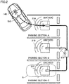
- Fig. 2 is a view for illustrating a manner in which a vehicle is being parked at a parking position within a charging station. First, an outline of the present embodiment will be described with reference to Figs. 1 and 2 .
- the contactless power transfer system of the present embodiment includes a vehicle 10 and a charging station 90.
- Charging station 90 includes a communication unit 810, parking sections A to C, and power transmission units 700A to 700C provided within respective parking sections A to C, respectively.
- a "vehicle stop region R" in Fig. 2 indicates a region where vehicle 10 is located when vehicle 10 stops such that a power reception unit 100 of vehicle 10 faces any of power transmission units 700A to 700C of charging station 90.
- FIG. 2 shows the vehicle stop region related to power transmission unit 700C of a power transmission device 20C, as a matter of course, each of power transmission units 700A, 700B of power transmission devices 20A, 20B also has a vehicle stop region.
- Communication unit 810 is configured to send a signal to reach inside vehicle stop region R and outside vehicle stop region R.
- the signal sending area of communication unit 810 is in a range with a radius of, for example, 5 to 10 meters centered at communication unit 810.
- communication unit 810 sends a signal to reach not only inside parking sections A to C but also a position several meters away from parking sections A to C. If vehicle 10 is located inside parking sections A to C or within a range of several meters from parking sections A to C, vehicle 10 can receive the signal from charging station 90.
- Vehicle 10 includes a communication unit 510 configured to transmit a signal from not only inside the parking sections but also outside parking sections A to C (for example, a position about 5 to 10 meters away from parking sections A to C) to charging station 90 to be received by charging station 90, power reception unit 100 configured to contactlessly receive electric power from power transmission units 700A to 700C, a display unit 520 for informing a user of a relative positional relation between power reception unit 100 and power transmission units 700A to 700C, and a control unit (vehicle ECU 500) configured to control communication unit 510, power reception unit 100, and display unit 520.
- a communication unit 510 configured to transmit a signal from not only inside the parking sections but also outside parking sections A to C (for example, a position about 5 to 10 meters away from parking sections A to C) to charging station 90 to be received by charging station 90
- power reception unit 100 configured to contactlessly receive electric power from power transmission units 700A to 700C
- a display unit 520 for informing a user of a relative positional relation between
- charging station 90 includes sensors 21A to 21C provided in respective parking sections A to C, respectively. Sensors 21A to 21C detect whether or not there is a vehicle stopping inside parking sections A to C, respectively.
- charging station 90 determines that no vehicle stops in at least one of parking sections A to C based on outputs from sensors 21A to 21C, charging station 90 sends a broadcast signal informing that charging station 90 can transmit electric power, to the surroundings.
- charging station 90 determines that vehicles stop in all parking sections A to C based on outputs from sensors 21A to 21C, charging station 90 does not send the broadcast signal to the surroundings. Thereby, vehicle 10 is guided into charging station 90 when there is a vacant parking section.
- each of power reception unit 100 and power transmission units 700A to 700C is constituted by a resonance circuit including a coil and a capacitor. Further, each of power transmission units 700A to 700C is configured to be able to form a plurality of resonance circuits having circuit configurations different from each other.
- charging station 90 receives the information about the resonance circuit of power reception unit 100
- a resonance circuit of the plurality of resonance circuits which has a circuit configuration identical to that of the resonance circuit of power reception unit 100 is formed in a power transmission unit corresponding to a parking section where no vehicle stops. Thereby, the power transmission unit of the parking section into which vehicle 10 is guided and power reception unit 100 of vehicle 10 can have resonance circuits having an identical configuration.
- vehicle 10 sends a signal for requesting to output electric power for position check for performing alignment of vehicle 10 relative to the parking section, to the surroundings.
- the electric power for position check is electric power output from charging station 90 when the alignment of vehicle 10 relative to the parking section is performed, and the alignment of vehicle 10 is performed based on a received voltage obtained when the electric power for position check is received by vehicle 10.
- the above request signal is sent to reach a range of about 5 to 10 meters centered at vehicle 10. Thereby, even when vehicle 10 is located outside parking sections A to C, charging station 90 can receive the request signal.
- charging station 90 When charging station 90 receives the request signal, charging station 90 supplies the electric power for position check to power transmission units 700A to 700C provided inside at least vacant parking sections A to C. Then, vehicle ECU 500 causes display unit 520 to display a positional relation between power reception unit 100 and any of power transmission units 700A to 700C, based on a received voltage VR generated by the electric power received by power reception unit 100. With such a configuration, vehicle 10 can be reliably charged, because power transfer is actually performed between a power transmission unit and the power reception unit and alignment can be performed in accordance with a result thereof.
- vehicle 10 includes a contactless charging switch 530 to be operated by the user, and, in a case where vehicle 10 receives the broadcast signal when contactless charging switch 530 is ON, vehicle 10 sends the request signal for requesting to output the electric power for position check, to the surroundings.
- the user may turn contactless charging switch 530 ON, and thereby alignment between the power reception unit and a power transmission unit can be performed based on the received voltage.
- vehicle ECU 500 performs pairing processing for causing charging station 90 to identify with which of power transmission units 700A to 700C power reception unit 100 is aligned, between vehicle ECU 500 and charging station 90.
- pairing processing the power transmission unit with which power reception unit 100 is aligned can be identified, even when the charging station is charging station 90 having the plurality of power transmission units 700A to 700C.
- the above pairing processing includes processing in which a plurality of patterns of power transmission different from each other are transmitted from power transmission units 700A to 700C, respectively, and power reception unit 100 transmits a signal corresponding to a received pattern of power transmission, from communication unit 510 to communication unit 810.
- the plurality of patterns of power transmission are power transmission in which electric power is transmitted for power transmission times different from each other within a predetermined period ( Fig. 9 ).
- the plurality of patterns of power transmission may be power transmission in which electric power is transmitted to repeat ON and OFF in patterns different from each other within a predetermined period ( Fig. 12 ).
- the contactless power transfer system of the present embodiment includes vehicle 10 equipped with a power reception device 140 configured to be able to contactlessly receive electric power, and charging station 90 including power transmission devices 20A, 20B, 20C configured to transmit electric power from outside the vehicle to power reception unit 100.
- Vehicle 10 includes power reception device 140, a power storage device 300, a motive power generation device 400, vehicle ECU 500, communication unit 510, display unit 520, and contactless charging switch 530.
- Power reception device 140 includes power reception unit 100, a filter circuit 150, and a rectification unit 200.
- Charging station 90 includes an external power source 900, power transmission devices 20A, 20B, 20C, a power supply ECU 800, and communication unit 810.
- Power transmission devices 20A, 20B, 20C include power supply units 600A, 600B, 600C, filter circuits 610A, 610B, 610C, and power transmission units 700A, 700B, 700C, respectively.
- power transmission devices 20A, 20B, 20C are provided on or in the ground of parking positions A, B, C, respectively, and power reception device 140 is arranged at a lower part of the body of the vehicle. It should be noted that the location of arranging power reception device 140 is not limited thereto. For example, if power transmission devices 20A, 20B, 20C are provided above vehicle 10, power reception device 140 may be provided at an upper part of the body of the vehicle.
- Power reception unit 100 includes a resonance circuit for contactlessly receiving (alternating current: AC) power output from any of power transmission units 700A, 700B, 700C of power transmission devices 20A, 20B, 20C.
- the resonance circuit is constituted by a coil and a capacitor. The configuration of the resonance circuit will be described later.
- Power reception unit 100 outputs the received power to rectification unit 200.
- Rectification unit 200 rectifies the AC power received by power reception unit 100, and outputs the rectified AC power to power storage device 300.
- Filter circuit 150 is provided between power reception unit 100 and rectification unit 200 to suppress harmonic noise generated during power reception.
- Filter circuit 150 is constituted by an LC filter including an inductor and a capacitor, for example.
- Power storage device 300 is a rechargeable direct current (DC) power source, and is constituted by a secondary battery such as a lithium ion battery or a nickel-hydrogen battery, for example. Power storage device 300 has a voltage of about 200 V, for example. Power storage device 300 stores the electric power output from rectification unit 200, and also stores electric power generated by motive power generation device 400. Power storage device 300 supplies the stored electric power to motive power generation device 400. It should be noted that a large-capacity capacitor can also be adopted as power storage device 300. Although not shown in particular, a DC-DC converter for adjusting an output voltage of rectification unit 200 may be provided between rectification unit 200 and power storage device 300.
- DC-DC converter for adjusting an output voltage of rectification unit 200 may be provided between rectification unit 200 and power storage device 300.
- Motive power generation device 400 generates a traveling drive force for vehicle 10 using the electric power stored in power storage device 300.
- motive power generation device 400 includes, for example, an inverter which receives the electric power from power storage device 300, a motor driven by the inverter, drive wheels driven by the motor, and the like.
- motive power generation device 400 may include a power generator for charging power storage device 300, and an engine which can drive the power generator.
- Vehicle ECU 500 includes a CPU (Central Processing Unit), a storage device, an input/output buffer, and the like (which are not shown), performs input of signals from various sensors and output of control signals to apparatuses, as well as performs control of apparatuses in vehicle 10. As an example, vehicle ECU 500 performs control of traveling of vehicle 10, and control of charging of power storage device 300. Further, vehicle ECU 500 transmits the information about the resonance circuit of power reception unit 100 to charging station 90, through communication unit 510. These controls can be processed not only by software but also by dedicated hardware (electronic circuitry).
- a relay 210 is provided between rectification unit 200 and power storage device 300. Relay 210 is turned ON by vehicle ECU 500 when power storage device 300 is charged by power transmission devices 20A, 20B, 20C. Further, a system main relay (SMR) 310 is provided between power storage device 300 and motive power generation device 400. SMR 310 is turned ON by vehicle ECU 500 when activation of motive power generation device 400 is requested. Furthermore, a resistor 201 is provided between a pair of the power lines between rectification unit 200 and relay 210, and a relay 202 is connected in series with resistor 201. Voltage VR across resistor 201 is detected by a voltage sensor 203, and is transmitted to vehicle ECU 500.
- SMR system main relay
- vehicle ECU 500 communicates with communication unit 810 of charging station 90 using communication unit 510, to transmit the information about the resonance circuit constituting power reception unit 100 to charging station 90, and to exchange information about start/stop of power transfer, a power reception condition of vehicle 10, and the like with power supply ECU 800.
- vehicle 10 or charging station 90 determines whether power reception unit 100 of vehicle 10 is aligned with power transmission unit 700A of power transmission device 20A, based on a vehicle-mounted camera not shown, the intensity of the electric power for position check output from power transmission unit 700A and received in vehicle 10, and the like, and informs the user of the determination through display unit 520. Based on the information obtained through display unit 520, the user moves vehicle 10 such that the positional relation between power reception device 140 and power transmission device 20A is suitable for power reception and transmission. It should be noted that the user does not necessarily have to operate a steering wheel or an accelerator, and vehicle 10 may move automatically for alignment and the user may watch movement of vehicle 10 through display unit 520. It should be noted that, instead of being informed through display unit 520 which visually informs the user of the information, the user may be audibly informed of the information.
- power supply units 600A, 600B, 600C receive electric power from external power source 900 such as a commercial system power source, to generate AC power having a predetermined transfer frequency.
- Each of power transmission units 700A, 700B, 700C is configured to be able to form the plurality of resonance circuits having circuit configurations different from each other.
- Each power transmission unit includes a coil and a capacitor, and switching means for switching the circuit configurations of the resonance circuits by switching connection configurations between the coil and the capacitor. The configuration of each power transmission unit will be described later.
- Power transmission units 700A, 700B, 700C receive the AC power having the transfer frequency from power supply units 600A, 600B, 600C, respectively, and contactlessly transmit the AC power to power reception unit 100 of vehicle 10, via electromagnetic fields generated around power transmission units 700A, 700B, 700C.
- Filter circuits 610A, 610B, 610C are provided between power supply units 600A, 600B, 600C and power transmission units 700A, 700B, 700C to suppress harmonic noise generated from power supply units 600A, 600B, 600C.
- Filter circuits 610A, 610B, 610C are each constituted by an LC filter including an inductor and a capacitor.
- Power supply ECU 800 includes a CPU, a storage device, an input/output buffer, and the like (which are not shown), performs input of signals from various sensors and output of control signals to apparatuses, as well as performs control of apparatuses in charging station 90. As an example, power supply ECU 800 performs control of switching of power supply units 600A, 600B, 600C such that power supply units 600A, 600B, 600C generate the AC power having the transfer frequency.
- power supply ECU 800 controls power transmission units 700A to 700C such that a resonance circuit of the plurality of resonance circuits which has a circuit configuration identical to that of the resonance circuit of power reception unit 100 is formed in a power transmission unit corresponding to a parking section where no vehicle stops. It should be noted that these controls can be processed not only by software but also by dedicated hardware (electronic circuitry).
- power supply ECU 800 communicates with communication unit 510 of vehicle 10 using communication unit 810, to receive the information about the resonance circuit constituting power reception unit 100 from vehicle 10, and to exchange information about start/stop of power transmission, the power reception condition of vehicle 10, and the like with vehicle 10.
- the AC power having the predetermined transfer frequency is supplied from power supply units 600A, 600B, 600C to power transmission units 700A, 700B, 700C via filter circuits 610A, 610B, 610C.
- Each of power transmission units 700A, 700B, 700C and power reception unit 100 of vehicle 10 includes a coil and a capacitor, and is designed to resonate at the transfer frequency.
- a Q factor indicating the intensity of resonance between power transmission units 700A, 700B, 700C and power reception unit 100 is more than or equal to 100.
- insulating transformers may be provided between power transmission units 700A, 700B, 700C and power supply units 600A, 600B, 600C (for example, between power transmission units 700A, 700B, 700C and filter circuits 610A, 610B, 610C) in power transmission devices 20A, 20B, 20C.
- an insulating transformer may be provided between power reception unit 100 and rectification unit 200 (for example, between power reception unit 100 and filter circuit 150).
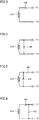
- Figs. 3 to 6 are views showing examples of the configuration of the resonance circuit constituting power reception unit 100 of vehicle 10.
- Power reception unit 100 is constituted by the resonance circuit shown in any of Figs. 3 to 6 .
- power reception unit 100 includes a coil 110 and a capacitor 120. Capacitor 120 is connected in series with coil 110. That is, this power reception unit 100 is constituted by a resonance circuit having the S (Series) configuration.
- power reception unit 100 in another example includes coil 110 and a capacitor 130. Capacitor 130 is connected in parallel with coil 110. That is, this power reception unit 100 is constituted by a resonance circuit having the P (Parallel) configuration.
- power reception unit 100 in still another example includes coil 110 and capacitors 120, 130.
- Capacitor 120 is connected in series with coil 110.
- Capacitor 130 is connected in parallel with coil 110 on a side closer to coil 110 than capacitor 120. That is, this power reception unit 100 is constituted by a resonance circuit having the SP configuration.
- power reception unit 100 in still another example includes coil 110 and capacitors 120, 130.
- Capacitor 130 is connected in parallel with coil 110.
- Capacitor 120 is connected in series with coil 110 on a side closer to coil 110 than capacitor 130. That is, this power reception unit 100 is constituted by a resonance circuit having the PS configuration.
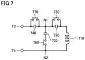
- Fig. 7 is a view showing an example of a configuration of power transmission unit 700A of power transmission device 20A. It should be noted that, in the present embodiment, charging station 90 includes power transmission units 700B, 700C, and power transmission units 700B, 700C also have a configuration identical to that of power transmission unit 700A.
- power transmission unit 700A includes a coil 710, capacitors 720, 730, 740, and relays 750, 760, 770.
- Capacitor 720 is connected between one end of coil 710 and a node N1.
- Capacitor 730 is provided in parallel with coil 710, and one end of capacitor 730 is connected to node N1.
- Capacitor 740 is connected between node N1 and a terminal T3 connected to filter circuit 610A ( Fig. 1 ). That is, capacitors 720, 740 are provided in series with coil 710, and capacitor 730 is provided in parallel with coil 710.
- Relays 750, 770 are connected in parallel with capacitors 720, 740, respectively.
- Relay 760 is connected in series with capacitor 730. It should be noted that relay 760 may be provided between node N1 and capacitor 730.
- Relays 750, 760, 770 are controlled to be ON or OFF by power supply ECU 800 ( Fig. 1 ).
- power transmission unit 700A can form a resonance circuit having any of the S configuration, the P configuration, the SP configuration, and the PS configuration. That is, a resonance circuit having the S configuration is formed by setting relays 750, 760, 770 to OFF, OFF, ON, respectively. Further, a resonance circuit having the P configuration is formed by setting all relays 750, 760, 770 to ON. Further, a resonance circuit having the SP configuration is formed by setting relays 750, 760, 770 to ON, ON, OFF, respectively. Further, a resonance circuit having the PS configuration is formed by setting relays 750, 760, 770 to OFF, ON, ON, respectively.
- the information about the resonance circuit of power reception unit 100 (specifically, the type of the configuration of the resonance circuit) is transmitted from vehicle 10 to charging station 90. Then, a resonance circuit having a configuration identical to that of the resonance circuit of power reception unit 100 is formed by appropriately operating relays 750 to 770 in power transmission units 700A to 700C where no vehicle stops.
- each of power transmission units 700A to 700C may include resonance circuits having the S configuration, the P configuration, the SP configuration, and the PS configuration, and the resonance circuits themselves may be switchable.
- Fig. 8 is a flowchart for illustrating an outline of processing performed by vehicle 10 and charging station 90 when contactless power transfer is performed.
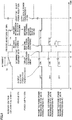
- Fig. 9 is a timing chart showing changes in transmitted power and received voltage changing in the course of the processing of Fig. 8 .
- charging station 90 when power supply ECU 800 determines that at least one of parking sections A to C is vacant based on outputs from sensors 21A to 21C, charging station 90 sends the broadcast signal informing that charging station 90 is in a condition where it can transmit electric power, to the surroundings (step S510).
- vehicle ECU 500 determines whether or not contactless charging switch 530 is "ON” (step S10).
- Contactless charging switch 530 is in an “ON” state unless it is operated by the user, and is turned “OFF” by being operated by the user.
- vehicle ECU 500 determines that contactless charging switch 530 is "OFF” (NO in step S10), vehicle ECU 500 terminates the processing without performing a series of subsequent steps.
- step S10 vehicle ECU 500 determines whether or not the broadcast signal is received from charging station 90 (step S20). When the broadcast signal is not received (NO in step S20), the processing returns to step S10.
- step S20 When the broadcast signal is received in vehicle 10 (YES in step S20), the information about the resonance circuit of power reception unit 100 is transmitted from vehicle 10 to charging station 90, and determination processing for determining whether or not power can be transferred from charging station 90 to vehicle 10 is performed in vehicle ECU 500 of vehicle 10 and power supply ECU 800 of charging station 90 (steps S30, S530). This determination processing will be described later in detail.
- step S40 When it is determined that power cannot be transferred from charging station 90 to vehicle 10, the processing is terminated in vehicle 10 and charging station 90. On the other hand, when it is determined that power can be transferred from charging station 90 to vehicle 10, vehicle ECU 500 of vehicle 10 transmits a signal for requesting to output electric power for position check, to charging station 90 (step S40).
- power supply ECU 800 controls power supply units 600A to 600C such that the electric power for position check is output from a power transmission unit of a parking section where no vehicle stops (step S550). It should be noted that, in a case where sensors 21A to 21C are not provided, power supply ECU 800 cannot recognize in which parking section the vehicle is being parked. Accordingly, in this case, power supply ECU 800 controls power supply units 600A to 600C such that the electric power for position check is output from all of the power transmission units of the parking sections in which full-scale power transmission for charging power storage device 300 is not performed.
- vehicle ECU 500 When the electric power for position check is received in vehicle 10, vehicle ECU 500 performs alignment by automatically or manually moving vehicle 10 based on the received voltage (step S50) (see time t1 in Fig. 9 ). At the time of the alignment, vehicle ECU 500 brings relay 202 into conduction to obtain received voltage VR generated across resistor 201 detected by voltage sensor 203. Since received voltage VR at the time of the alignment is lower than a received voltage at the time of the full-scale power transmission for charging power storage device 300 (charging voltage), relay 210 is turned OFF so as not be influenced by power storage device 300 at the time of voltage detection.
- step S60 When received voltage VR exceeds a threshold TH, completion of the alignment is displayed on display unit 520. Thereafter, when the user presses a parking switch inside vehicle 10 and thereby it is determined that the parking position is OK (YES in step S60), vehicle ECU 500 transmits a signal for requesting to stop transmission of the electric power for position check, to charging station 90 (step S70) (see time t2 in Fig. 9 ).
- power supply ECU 800 stops transmission of the electric power for position check by power transmission device 20A, 20B, 20C (step S560) (see time t3 in Fig. 9 ).
- a transmitted voltage (output voltage from power transmission device 20A, 20B, 20C) is constant, whereas received voltage VR in vehicle 10 changes in accordance with the distance between the coil of power transmission device 20A, 20B, 20C and the coil of power reception device 140. Accordingly, the relation between received voltage VR and the difference in horizontal position between the center of gravity O1 of a core of the coil on the power transmission side and the center of gravity O2 of a core of the coil on the power reception side is measured beforehand, and received voltage VR for an acceptable value of the difference in horizontal position between the center of gravity O1 of the core and the center of gravity O2 of the core is set as threshold TH.
- vehicle ECU 500 and power supply ECU 800 perform pairing processing for identifying with which of power transmission devices 20A, 20B, 20C the alignment is performed (steps S80, S580).
- Power supply ECU 800 causes each power transmission device to have a different duration for which transmitted power is ON. That is, power transmission device 20A sets the transmitted power to ON for a time TA, power transmission device 20B sets the transmitted power to ON for a time TB, and power transmission device 20C sets the transmitted power to ON for a time TC (see time t4 in Fig. 9 ).
- vehicle ECU 500 informs power supply ECU 800 of a duration for which received power is ON.
- power reception device 140 receives the transmitted power from power transmission device 20A.
- Vehicle ECU 500 informs power supply ECU 800 that the duration for which the received power is ON is TA. Thereby, power supply ECU 800 recognizes that the alignment is performed with power transmission device 20A.
- charging station 90 performs full-scale power transmission processing for charging power storage device 300 by a power transmission device with which the alignment is performed and for which identification by pairing is completed (see time t6 in Fig. 9 ).
- power transmission device 20A performs the power transmission processing.
- full-scale power reception processing for charging power storage device 300 is performed by power reception device 140, and power storage device 300 is charged with the received power. Then, when charging of power storage device 300 is completed, the processing in vehicle 10 and charging station 90 is terminated.
- Fig. 10 is a flowchart illustrating processing for determination of whether or not power can be transferred, performed in steps S30 and S530 shown in Fig. 8 .
- vehicle ECU 500 transmits the information about the resonance circuit of power reception unit 100 to charging station 90 (step S 100).
- This information about the resonance circuit at least includes information about which of the S configuration, the P configuration, the SP configuration, and the PS configuration the resonance circuit is constituted by, and may further include information about the capacity of capacitor 120 (130), the size of coil 110, and the like.
- power supply ECU 800 determines whether or not power can be transferred from charging station 90 to vehicle 10, based on the received information (step S 104). Specifically, whether or not power can be transferred from charging station 90 to vehicle 10 is determined based on whether or not a resonance circuit having a circuit configuration identical to that of the resonance circuit of power reception unit 100 can be formed in power transmission units 700A to 700C, and if such a resonance circuit can be formed, whether or not coil 110 of power reception unit 100 has an appropriate size, and the like.
- step S104 When power supply ECU 800 determines in step S104 that power can be transferred from charging station 90 to vehicle 10 (YES in step S104), power supply ECU 800 controls relays 750 to 770 such that a resonance circuit having a circuit configuration identical to that of the resonance circuit of power reception unit 100 is formed in a power transmission unit of a parking section where no vehicle stops (step S105). Then, power supply ECU 800 transmits information about power transfer from charging station 90 to vehicle 10, to vehicle 10 (step S106). It should be noted that this information includes, for example, information about the range of electric power which can be output from charging station 90, and the like.
- step S104 When power supply ECU 800 determines in step S104 that power cannot be transferred from charging station 90 to vehicle 10 (NO in step S 104), power supply ECU 800 transmits information indicating that power cannot be transferred, to vehicle 10 (step S108).
- step S I 10 vehicle ECU 500 determines whether or not power can be received from charging station 90, based on the received information (step S112).
- vehicle ECU 500 determines the magnitude of received power received from charging station 90 (step S114).
- step S116 an alarm indicating that power cannot be received is output (step S116).
- the information about the resonance circuit of power reception unit 100 is transmitted from vehicle 10 to charging station 90.
- Each of power transmission units 700A to 700C of charging station 90 can form a resonance circuit of a plurality of types (the S configuration, the P configuration, the SP configuration, the PS configuration), and a resonance circuit having a circuit configuration identical to that of the resonance circuit of power reception unit 100 is formed in a power transmission unit of a parking section where no vehicle stops, based on the information about the resonance circuit of power reception unit 100. That is, the power transmission unit of charging station 90 and power reception unit 100 of vehicle 10 have resonance circuits having an identical circuit configuration. Therefore, according to the present embodiment, it is possible to suppress impedance mismatching between charging station 90 and vehicle 10 due to the difference in the circuit configuration of the resonance circuit between power transmission units 700A to 700C and power reception unit 100.
- determination of whether or not power can be transferred is performed in charging station 90 in the above description as shown in Fig. 10 , the determination may be performed in vehicle 10.
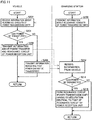
- Fig. 11 is a flowchart illustrating processing for determination of whether or not power can be transferred in a first variation. It should be noted that this flowchart corresponds to Fig. 10 , and the entire processing for power transfer is identical to the processing in the first embodiment shown in Fig. 8 .
- power supply ECU 800 transmits information about the resonance circuit of each of power transmission units 700A to 700C to vehicle 10 (step S200). It should be noted that this information at least includes information about the configuration of a resonance circuit which can be formed in each of power transmission units 700A to 700C, and may include information about the capacity of capacitors 720 to 740, the size of coil 710, and the like.
- vehicle ECU 500 determines whether or not power can be transferred from charging station 90 to vehicle 10, based on the received information (step S204). Specifically, whether or not power can be transferred from charging station 90 to vehicle 10 is determined based on whether or not a resonance circuit having a circuit configuration identical to that of the resonance circuit of power reception unit 100 can be formed in power transmission units 700A to 700C, and if such a resonance circuit can be formed, whether or not coil 710 of each of power transmission units 700A to 700C has an appropriate size, and the like.
- vehicle ECU 500 determines in step S204 that power can be transferred from charging station 90 to vehicle 10 (YES in step S204)
- vehicle ECU 500 transmits information about power transfer and information about the resonance circuit of power reception unit 100 to charging station 90 (step S206).
- the information about power transfer includes, for example, information about the range of electric power which can be received by vehicle 10, and the like.
- the information about the resonance circuit of power reception unit 100 at least includes information about which of the S configuration, the P configuration, the SP configuration, and the PS configuration the resonance circuit is constituted by, and may further include information about the capacity of capacitor 120 (130), the size of coil 110, and the like.
- vehicle ECU 500 determines in step S204 that power cannot be transferred from charging station 90 to vehicle 10 (NO in step S204), vehicle ECU 500 transmits information indicating that power cannot be transferred, to charging station 90 (step S208).
- step S212 When the information (the information about power transfer and the resonance circuit, or the information indicating that power cannot be transferred) from vehicle 10 is received in charging station 90 (step S212), power supply ECU 800 determines whether or not power can be transmitted to vehicle 10, based on the received information (step S214). When power supply ECU 800 determines that power can be transmitted (YES in step S214), power supply ECU 800 controls relays 750 to 770 such that a resonance circuit having a circuit configuration identical to that of the resonance circuit of power reception unit 100 is formed in a power transmission unit of a parking section where no vehicle stops (step S216). When power supply ECU 800 determines in step S214 that power cannot be transmitted, the processing is terminated without performing processing in step S216.
- a variation of the pairing processing is illustrated in a second variation.
- Fig. 12 is a view for illustrating a variation of the pairing processing.
- power supply ECU 800 causes each power transmission device to have a different cycle for switching ON and OFF of transmitted power. That is, power transmission device 20A switches ON and OFF of the transmitted power in a cycle of ⁇ TA, power transmission device 20B switches ON and OFF of the transmitted power in a cycle of ⁇ TB, and power transmission device 20C switches ON and OFF of the transmitted power in a cycle of ⁇ TC (see times t4 to t5 in Fig. 12 ).
- Vehicle ECU 500 informs power supply ECU 800 of a cycle for switching ON and OFF of received power.
- power reception device 140 receives the transmitted power from power transmission device 20A.
- Vehicle ECU 500 informs power supply ECU 800 that the cycle for switching ON and OFF of the received power is ⁇ TA.
- power supply ECU 800 recognizes that the alignment is performed with power transmission device 20A (see time t5 in Fig. 12 ).
- pairing is performed using transmitted power
- the method for the pairing processing is not limited thereto. Pairing can be performed using various techniques, and for example, pairing may be performed using an RFID (Radio Frequency IDentification) technique, by providing an RFID tag and an RFID reader to a vehicle and a power transmission unit, respectively.
- RFID Radio Frequency IDentification
- power reception unit 100 of vehicle 10 has a resonance circuit having a certain configuration, and any of a plurality of resonance circuits can be selectively formed in each of power transmission units 700A to 700C of the charging station.
- each of the power transmission units of the charging station has a resonance circuit having a certain configuration, and any of a plurality of resonance circuits can be selectively formed in the power reception unit of the vehicle, although not shown in particular.
- a resonance circuit having a circuit configuration identical to that of the resonance circuit of power reception unit 100 is formed in a power transmission unit of charging station 90 in the embodiment and the variations described above, the circuit configuration of the power transmission unit may be different from the circuit configuration of power reception unit 100 as long as appropriate current-voltage characteristics can be obtained.
- a resonance circuit having the S configuration may be formed in the power transmission unit
- a resonance circuit having the SP configuration may be formed in the power transmission unit.
Landscapes
- Engineering & Computer Science (AREA)
- Power Engineering (AREA)
- Transportation (AREA)
- Mechanical Engineering (AREA)
- Computer Networks & Wireless Communication (AREA)
- Life Sciences & Earth Sciences (AREA)
- Sustainable Development (AREA)
- Sustainable Energy (AREA)
- Electric Propulsion And Braking For Vehicles (AREA)
- Charge And Discharge Circuits For Batteries Or The Like (AREA)
Claims (3)
- Dispositif de transmission d'énergie, comprenant :une unité de transmission d'énergie (700A), incluant une bobine (710) et trois condensateurs (720, 730, 740) et configurée pour transmettre sans contact de l'énergie électrique à un véhicule (10) ;un premier dispositif de communication (810) configuré pour communiquer avec le véhicule,le véhicule incluant un circuit de résonance pour la réception d'énergie (110, 120 ; 110, 130 ; 110, 120, 130) configuré pour recevoir sans contact l'énergie électrique délivrée en sortie de l'unité de transmission d'énergie,l'unité de transmission d'énergie étant configurée pour être apte à former une pluralité de circuits de résonance pour la transmission d'énergie (710, 720 ; 710, 730 ; 710, 730, 740 ; 710, 720, 730) ayant des configurations de circuit différentes les unes des autres,le premier dispositif de communication étant configuré pour recevoir des informations concernant le circuit de résonance pour la réception d'énergie à partir du véhicule,caractérisé en ce quele circuit de résonance pour la réception d'énergie du véhicule inclut une bobine et au moins un condensateur connecté selon l'une quelconque parmi une configuration S (110, 120), une configuration P (110, 130), une configuration SP (110, 120, 130) et une configuration PS (110, 120, 130), dans lequeldans la configuration S, le condensateur est connecté en série avec la bobine,dans la configuration P, le condensateur est connecté en parallèle avec la bobine,dans la configuration SP, un autre condensateur est en outre connecté en série avec un circuit ayant la configuration P, etdans la configuration PS, un autre condensateur est en outre connecté en parallèle avec un circuit ayant la configuration S ; etle dispositif de transmission d'énergie comprend :
un dispositif de commande (800) configuré pour commander l'unité de transmission d'énergie pour former un circuit de résonance dans l'unité de transmission d'énergie sur la base des informations issues du véhicule reçues par le premier dispositif de communication, dans lequel les informations étant des informations indiquant laquelle parmi les configurations S, P, SP ou PS est la configuration du circuit de résonance pour la réception d'énergie, et dans lequelle dispositif de commande commandant l'unité de transmission d'énergie pour former un circuit de résonance de la pluralité de circuits de résonance pour la transmission d'énergie dans l'unité de transmission d'énergie sur la base des informations issues du véhicule reçues par le premier dispositif de communication, le circuit de résonance pour la transmission d'énergie ayant un circuit configuration identique à celle du circuit de résonance pour la réception d'énergie. - Dispositif de transmission de puissance selon la revendication 1, dans lequel l'unité de transmission d'énergie inclut un circuit de commutation (750 à 770) pour former sélectivement le circuit de résonance pour la transmission d'énergie.
- Système de transfert d'énergie sans contact, comprenant :le dispositif de transmission d'énergie (90) selon la revendication 1 ou la revendication 2 ; etun véhicule (10) configuré pour recevoir sans contact de l'énergie électrique à partir du dispositif de transmission d'énergie,le véhicule incluant :un circuit de résonance pour la réception d'énergie (110, 120 ; 110, 130 ; 110, 120, 130) configuré pour recevoir sans contact l'énergie électrique délivrée en sortie de l'unité de transmission d'énergie (700A) du dispositif de transmission d'énergie ; etun second dispositif de communication (510) configuré pour communiquer avec le dispositif de transmission d'énergie,l'unité de transmission d'énergie étant configurée pour être apte à former une pluralité de circuits de résonance pour la transmission d'énergie (710, 720 ; 710, 730 ; 710, 730, 740 ; 710, 720, 730) ayant des configurations de circuit différentes les unes des autres,le second dispositif de communication transmettant des informations concernant le circuit de résonance pour la réception d'énergie au premier dispositif de communication (810),le dispositif de commande (800) du dispositif de transmission d'énergie commandant l'unité de transmission d'énergie, lorsque les informations sont reçues par le premier dispositif de communication, pour former un circuit de résonance dans l'unité de transmission d'énergie sur la base des informations reçues.
Applications Claiming Priority (2)
| Application Number | Priority Date | Filing Date | Title |
|---|---|---|---|
| JP2013252149A JP5842901B2 (ja) | 2013-12-05 | 2013-12-05 | 非接触電力伝送システム |
| PCT/JP2014/081021 WO2015083573A1 (fr) | 2013-12-05 | 2014-11-25 | Système de transmission d'énergie sans contact et dispositif de transmission électrique |
Publications (3)
| Publication Number | Publication Date |
|---|---|
| EP3082223A1 EP3082223A1 (fr) | 2016-10-19 |
| EP3082223A4 EP3082223A4 (fr) | 2017-01-11 |
| EP3082223B1 true EP3082223B1 (fr) | 2020-04-29 |
Family
ID=53273337
Family Applications (1)
| Application Number | Title | Priority Date | Filing Date |
|---|---|---|---|
| EP14867255.3A Active EP3082223B1 (fr) | 2013-12-05 | 2014-11-25 | Système de transmission d'énergie sans contact et dispositif de transmission électrique |
Country Status (5)
| Country | Link |
|---|---|
| US (1) | US10457149B2 (fr) |
| EP (1) | EP3082223B1 (fr) |
| JP (1) | JP5842901B2 (fr) |
| CN (2) | CN105814765B (fr) |
| WO (1) | WO2015083573A1 (fr) |
Families Citing this family (8)
| Publication number | Priority date | Publication date | Assignee | Title |
|---|---|---|---|---|
| JP6361132B2 (ja) | 2013-12-24 | 2018-07-25 | トヨタ自動車株式会社 | 非接触電力伝送システム、充電ステーション、および車両 |
| JP6056778B2 (ja) * | 2014-01-24 | 2017-01-11 | トヨタ自動車株式会社 | 非接触電力伝送システム |
| US10137794B2 (en) * | 2014-09-15 | 2018-11-27 | Stmicroelectronics, Inc. | Method and apparatus for a wireless charging system |
| JP6610503B2 (ja) * | 2016-10-31 | 2019-11-27 | トヨタ自動車株式会社 | 車両および供給装置 |
| JP6527554B2 (ja) * | 2017-06-22 | 2019-06-05 | 本田技研工業株式会社 | 非接触電力伝送システム |
| DE112019003311A5 (de) * | 2018-06-29 | 2021-03-18 | Brusa Elektronik Ag | Schaltvorrichtung für eine Spule |
| JP7459832B2 (ja) * | 2021-03-31 | 2024-04-02 | 株式会社デンソー | 非接触給電システムの異常検知装置及び異常検知方法 |
| TW202349826A (zh) * | 2022-05-03 | 2023-12-16 | 美商奇異電器公司 | 無線電力傳輸系統中之操作階段 |
Family Cites Families (27)
| Publication number | Priority date | Publication date | Assignee | Title |
|---|---|---|---|---|
| JPH11188113A (ja) * | 1997-12-26 | 1999-07-13 | Nec Corp | 電力伝送システムおよび電力伝送方法ならびにその電力伝送システムを備えた電気刺激装置 |
| US7296157B2 (en) * | 2002-07-10 | 2007-11-13 | Electronics For Imaging, Inc. | Methods and apparatus for secure document printing |
| US7825543B2 (en) | 2005-07-12 | 2010-11-02 | Massachusetts Institute Of Technology | Wireless energy transfer |
| KR101118710B1 (ko) | 2005-07-12 | 2012-03-13 | 메사추세츠 인스티튜트 오브 테크놀로지 | 무선 비-방사성 에너지 전달 |
| JP4308858B2 (ja) * | 2007-02-16 | 2009-08-05 | セイコーエプソン株式会社 | 送電制御装置、受電制御装置、無接点電力伝送システム、送電装置、受電装置および電子機器 |
| KR101356409B1 (ko) | 2007-03-27 | 2014-01-27 | 메사추세츠 인스티튜트 오브 테크놀로지 | 무선 에너지 전달 |
| WO2009055856A1 (fr) * | 2007-10-30 | 2009-05-07 | Cochlear Limited | Liaison électrique pour dispositifs implantables |
| JP2010016985A (ja) * | 2008-07-03 | 2010-01-21 | Sanyo Electric Co Ltd | 電力搬送における情報伝送方法とこの情報伝送方法を使用する充電台と電池内蔵機器 |
| US8291390B2 (en) * | 2008-07-30 | 2012-10-16 | National Instruments Corporation | Testing a graphical program intended for a programmable hardware element |
| US8598743B2 (en) * | 2008-09-27 | 2013-12-03 | Witricity Corporation | Resonator arrays for wireless energy transfer |
| JP5351499B2 (ja) * | 2008-11-28 | 2013-11-27 | 長野日本無線株式会社 | 非接触型電力伝送システム |
| CN102449711A (zh) * | 2009-07-02 | 2012-05-09 | 丰田自动车株式会社 | 线圈单元、非接触受电装置、非接触送电装置、非接触供电系统以及车辆 |
| JP5691458B2 (ja) * | 2010-03-31 | 2015-04-01 | 日産自動車株式会社 | 非接触給電装置及び非接触給電方法 |
| JP2011223739A (ja) | 2010-04-09 | 2011-11-04 | Sony Corp | 給電装置、受電装置、およびワイヤレス給電システム |
| JP5307073B2 (ja) * | 2010-05-14 | 2013-10-02 | 株式会社豊田自動織機 | 非接触受電システム及び非接触電力伝送システム |
| US9124122B2 (en) * | 2011-05-18 | 2015-09-01 | Samsung Electronics Co., Ltd. | Wireless power transmission and charging system, and impedance control method thereof |
| WO2012169015A1 (fr) * | 2011-06-07 | 2012-12-13 | パイオニア株式会社 | Dispositif d'appariement d'impédance et procédé de contrôle |
| JP2013005614A (ja) * | 2011-06-17 | 2013-01-07 | Toyota Motor Corp | 送電装置、受電装置、車両、および非接触給電システム |
| JP5772535B2 (ja) | 2011-11-18 | 2015-09-02 | トヨタ自動車株式会社 | 電力伝送システム及び車両 |
| JP5668676B2 (ja) | 2011-12-15 | 2015-02-12 | トヨタ自動車株式会社 | 受電装置およびそれを備える車両、送電装置、ならびに電力伝送システム |
| JP5718830B2 (ja) | 2012-01-16 | 2015-05-13 | トヨタ自動車株式会社 | 車両 |
| JP5825108B2 (ja) | 2012-01-16 | 2015-12-02 | トヨタ自動車株式会社 | 受電装置および送電装置 |
| JP5810944B2 (ja) | 2012-01-31 | 2015-11-11 | トヨタ自動車株式会社 | 車両および電力伝送システム |
| JP5649603B2 (ja) * | 2012-03-21 | 2015-01-07 | 株式会社東芝 | 送電装置および送電方法 |
| JP2013219899A (ja) | 2012-04-06 | 2013-10-24 | Toyota Industries Corp | 非接触電力伝送装置及び非接触電力伝送システム |
| JP5747863B2 (ja) * | 2012-05-11 | 2015-07-15 | トヨタ自動車株式会社 | 車両、受電装置、送電装置および非接触給電システム |
| JP6056778B2 (ja) * | 2014-01-24 | 2017-01-11 | トヨタ自動車株式会社 | 非接触電力伝送システム |
-
2013
- 2013-12-05 JP JP2013252149A patent/JP5842901B2/ja active Active
-
2014
- 2014-11-25 EP EP14867255.3A patent/EP3082223B1/fr active Active
- 2014-11-25 CN CN201480066148.3A patent/CN105814765B/zh active Active
- 2014-11-25 WO PCT/JP2014/081021 patent/WO2015083573A1/fr not_active Ceased
- 2014-11-25 CN CN201811023738.4A patent/CN109245186A/zh active Pending
- 2014-11-25 US US15/038,344 patent/US10457149B2/en active Active
Non-Patent Citations (1)
| Title |
|---|
| None * |
Also Published As
| Publication number | Publication date |
|---|---|
| WO2015083573A1 (fr) | 2015-06-11 |
| EP3082223A1 (fr) | 2016-10-19 |
| JP2015109769A (ja) | 2015-06-11 |
| EP3082223A4 (fr) | 2017-01-11 |
| CN109245186A (zh) | 2019-01-18 |
| JP5842901B2 (ja) | 2016-01-13 |
| CN105814765A (zh) | 2016-07-27 |
| CN105814765B (zh) | 2018-10-02 |
| US20160311337A1 (en) | 2016-10-27 |
| US10457149B2 (en) | 2019-10-29 |
Similar Documents
| Publication | Publication Date | Title |
|---|---|---|
| EP3082223B1 (fr) | Système de transmission d'énergie sans contact et dispositif de transmission électrique | |
| CN105848958B (zh) | 非接触式电力传输系统和控制该系统的方法 | |
| JP5937631B2 (ja) | 非接触電力伝送システムおよび充電ステーション | |
| JP6056778B2 (ja) | 非接触電力伝送システム | |
| US20160297305A1 (en) | Power transmitting device, and power transfer system | |
| JP5920371B2 (ja) | 非接触電力伝送システム | |
| US10899234B2 (en) | Non-contact electric power transmission system, charging station, and vehicle | |
| US10333355B2 (en) | Wireless charging magnetic parameter determination | |
| JP2015100230A (ja) | 非接触送受電システム | |
| EP2902252B1 (fr) | Système de transmission d'énergie électrique sans contact et poste de charge | |
| JP2015144529A (ja) | 非接触電力伝送システム、および充電ステーション | |
| JP2015100246A (ja) | 非接触電力伝送システム、充電ステーション、および車両 | |
| JP6160742B2 (ja) | 非接触電力伝送システム | |
| JP2018078793A (ja) | 車両、受電装置および送電装置 |
Legal Events
| Date | Code | Title | Description |
|---|---|---|---|
| PUAI | Public reference made under article 153(3) epc to a published international application that has entered the european phase |
Free format text: ORIGINAL CODE: 0009012 |
|
| 17P | Request for examination filed |
Effective date: 20160603 |
|
| AK | Designated contracting states |
Kind code of ref document: A1 Designated state(s): AL AT BE BG CH CY CZ DE DK EE ES FI FR GB GR HR HU IE IS IT LI LT LU LV MC MK MT NL NO PL PT RO RS SE SI SK SM TR |
|
| AX | Request for extension of the european patent |
Extension state: BA ME |
|
| A4 | Supplementary search report drawn up and despatched |
Effective date: 20161209 |
|
| RIC1 | Information provided on ipc code assigned before grant |
Ipc: B60L 11/18 20060101ALI20161205BHEP Ipc: H02J 50/12 20160101ALI20161205BHEP Ipc: H02J 5/00 20160101ALI20161205BHEP Ipc: B60M 7/00 20060101ALI20161205BHEP Ipc: H02J 7/00 20060101ALI20161205BHEP Ipc: H02J 50/00 20160101AFI20161205BHEP Ipc: H02J 7/02 20160101ALI20161205BHEP Ipc: H02J 50/80 20160101ALI20161205BHEP |
|
| DAX | Request for extension of the european patent (deleted) | ||
| STAA | Information on the status of an ep patent application or granted ep patent |
Free format text: STATUS: EXAMINATION IS IN PROGRESS |
|
| 17Q | First examination report despatched |
Effective date: 20180723 |
|
| REG | Reference to a national code |
Ref country code: DE Ref legal event code: R079 Ref document number: 602014064705 Country of ref document: DE Free format text: PREVIOUS MAIN CLASS: H02J0050000000 Ipc: H02J0050120000 |
|
| GRAP | Despatch of communication of intention to grant a patent |
Free format text: ORIGINAL CODE: EPIDOSNIGR1 |
|
| STAA | Information on the status of an ep patent application or granted ep patent |
Free format text: STATUS: GRANT OF PATENT IS INTENDED |
|
| RIC1 | Information provided on ipc code assigned before grant |
Ipc: H02J 7/00 20060101ALI20191018BHEP Ipc: H02J 50/90 20160101ALI20191018BHEP Ipc: B60M 7/00 20060101ALI20191018BHEP Ipc: B60L 53/30 20190101ALI20191018BHEP Ipc: H02J 50/40 20160101ALI20191018BHEP Ipc: B60L 53/12 20190101ALI20191018BHEP Ipc: B60L 50/50 20190101ALI20191018BHEP Ipc: B60L 53/38 20190101ALI20191018BHEP Ipc: H02J 5/00 20160101ALI20191018BHEP Ipc: H02J 50/80 20160101ALI20191018BHEP Ipc: H02J 7/02 20160101ALI20191018BHEP Ipc: H02J 50/12 20160101AFI20191018BHEP |
|
| INTG | Intention to grant announced |
Effective date: 20191119 |
|
| GRAS | Grant fee paid |
Free format text: ORIGINAL CODE: EPIDOSNIGR3 |
|
| GRAA | (expected) grant |
Free format text: ORIGINAL CODE: 0009210 |
|
| STAA | Information on the status of an ep patent application or granted ep patent |
Free format text: STATUS: THE PATENT HAS BEEN GRANTED |
|
| AK | Designated contracting states |
Kind code of ref document: B1 Designated state(s): AL AT BE BG CH CY CZ DE DK EE ES FI FR GB GR HR HU IE IS IT LI LT LU LV MC MK MT NL NO PL PT RO RS SE SI SK SM TR |
|
| REG | Reference to a national code |
Ref country code: GB Ref legal event code: FG4D |
|
| REG | Reference to a national code |
Ref country code: CH Ref legal event code: EP |
|
| REG | Reference to a national code |
Ref country code: DE Ref legal event code: R096 Ref document number: 602014064705 Country of ref document: DE |
|
| REG | Reference to a national code |
Ref country code: AT Ref legal event code: REF Ref document number: 1264764 Country of ref document: AT Kind code of ref document: T Effective date: 20200515 |
|
| REG | Reference to a national code |
Ref country code: IE Ref legal event code: FG4D |
|
| REG | Reference to a national code |
Ref country code: NL Ref legal event code: MP Effective date: 20200429 |
|
| REG | Reference to a national code |
Ref country code: LT Ref legal event code: MG4D |
|
| PG25 | Lapsed in a contracting state [announced via postgrant information from national office to epo] |
Ref country code: FI Free format text: LAPSE BECAUSE OF FAILURE TO SUBMIT A TRANSLATION OF THE DESCRIPTION OR TO PAY THE FEE WITHIN THE PRESCRIBED TIME-LIMIT Effective date: 20200429 Ref country code: LT Free format text: LAPSE BECAUSE OF FAILURE TO SUBMIT A TRANSLATION OF THE DESCRIPTION OR TO PAY THE FEE WITHIN THE PRESCRIBED TIME-LIMIT Effective date: 20200429 Ref country code: GR Free format text: LAPSE BECAUSE OF FAILURE TO SUBMIT A TRANSLATION OF THE DESCRIPTION OR TO PAY THE FEE WITHIN THE PRESCRIBED TIME-LIMIT Effective date: 20200730 Ref country code: PT Free format text: LAPSE BECAUSE OF FAILURE TO SUBMIT A TRANSLATION OF THE DESCRIPTION OR TO PAY THE FEE WITHIN THE PRESCRIBED TIME-LIMIT Effective date: 20200831 Ref country code: NO Free format text: LAPSE BECAUSE OF FAILURE TO SUBMIT A TRANSLATION OF THE DESCRIPTION OR TO PAY THE FEE WITHIN THE PRESCRIBED TIME-LIMIT Effective date: 20200729 Ref country code: IS Free format text: LAPSE BECAUSE OF FAILURE TO SUBMIT A TRANSLATION OF THE DESCRIPTION OR TO PAY THE FEE WITHIN THE PRESCRIBED TIME-LIMIT Effective date: 20200829 Ref country code: SE Free format text: LAPSE BECAUSE OF FAILURE TO SUBMIT A TRANSLATION OF THE DESCRIPTION OR TO PAY THE FEE WITHIN THE PRESCRIBED TIME-LIMIT Effective date: 20200429 |
|
| REG | Reference to a national code |
Ref country code: AT Ref legal event code: MK05 Ref document number: 1264764 Country of ref document: AT Kind code of ref document: T Effective date: 20200429 |
|
| PG25 | Lapsed in a contracting state [announced via postgrant information from national office to epo] |
Ref country code: BG Free format text: LAPSE BECAUSE OF FAILURE TO SUBMIT A TRANSLATION OF THE DESCRIPTION OR TO PAY THE FEE WITHIN THE PRESCRIBED TIME-LIMIT Effective date: 20200729 Ref country code: HR Free format text: LAPSE BECAUSE OF FAILURE TO SUBMIT A TRANSLATION OF THE DESCRIPTION OR TO PAY THE FEE WITHIN THE PRESCRIBED TIME-LIMIT Effective date: 20200429 Ref country code: RS Free format text: LAPSE BECAUSE OF FAILURE TO SUBMIT A TRANSLATION OF THE DESCRIPTION OR TO PAY THE FEE WITHIN THE PRESCRIBED TIME-LIMIT Effective date: 20200429 Ref country code: LV Free format text: LAPSE BECAUSE OF FAILURE TO SUBMIT A TRANSLATION OF THE DESCRIPTION OR TO PAY THE FEE WITHIN THE PRESCRIBED TIME-LIMIT Effective date: 20200429 |
|
| PG25 | Lapsed in a contracting state [announced via postgrant information from national office to epo] |
Ref country code: AL Free format text: LAPSE BECAUSE OF FAILURE TO SUBMIT A TRANSLATION OF THE DESCRIPTION OR TO PAY THE FEE WITHIN THE PRESCRIBED TIME-LIMIT Effective date: 20200429 Ref country code: NL Free format text: LAPSE BECAUSE OF FAILURE TO SUBMIT A TRANSLATION OF THE DESCRIPTION OR TO PAY THE FEE WITHIN THE PRESCRIBED TIME-LIMIT Effective date: 20200429 |
|
| PG25 | Lapsed in a contracting state [announced via postgrant information from national office to epo] |
Ref country code: AT Free format text: LAPSE BECAUSE OF FAILURE TO SUBMIT A TRANSLATION OF THE DESCRIPTION OR TO PAY THE FEE WITHIN THE PRESCRIBED TIME-LIMIT Effective date: 20200429 Ref country code: CZ Free format text: LAPSE BECAUSE OF FAILURE TO SUBMIT A TRANSLATION OF THE DESCRIPTION OR TO PAY THE FEE WITHIN THE PRESCRIBED TIME-LIMIT Effective date: 20200429 Ref country code: ES Free format text: LAPSE BECAUSE OF FAILURE TO SUBMIT A TRANSLATION OF THE DESCRIPTION OR TO PAY THE FEE WITHIN THE PRESCRIBED TIME-LIMIT Effective date: 20200429 Ref country code: IT Free format text: LAPSE BECAUSE OF FAILURE TO SUBMIT A TRANSLATION OF THE DESCRIPTION OR TO PAY THE FEE WITHIN THE PRESCRIBED TIME-LIMIT Effective date: 20200429 Ref country code: RO Free format text: LAPSE BECAUSE OF FAILURE TO SUBMIT A TRANSLATION OF THE DESCRIPTION OR TO PAY THE FEE WITHIN THE PRESCRIBED TIME-LIMIT Effective date: 20200429 Ref country code: SM Free format text: LAPSE BECAUSE OF FAILURE TO SUBMIT A TRANSLATION OF THE DESCRIPTION OR TO PAY THE FEE WITHIN THE PRESCRIBED TIME-LIMIT Effective date: 20200429 Ref country code: EE Free format text: LAPSE BECAUSE OF FAILURE TO SUBMIT A TRANSLATION OF THE DESCRIPTION OR TO PAY THE FEE WITHIN THE PRESCRIBED TIME-LIMIT Effective date: 20200429 Ref country code: DK Free format text: LAPSE BECAUSE OF FAILURE TO SUBMIT A TRANSLATION OF THE DESCRIPTION OR TO PAY THE FEE WITHIN THE PRESCRIBED TIME-LIMIT Effective date: 20200429 |
|
| REG | Reference to a national code |
Ref country code: DE Ref legal event code: R097 Ref document number: 602014064705 Country of ref document: DE |
|
| PG25 | Lapsed in a contracting state [announced via postgrant information from national office to epo] |
Ref country code: SK Free format text: LAPSE BECAUSE OF FAILURE TO SUBMIT A TRANSLATION OF THE DESCRIPTION OR TO PAY THE FEE WITHIN THE PRESCRIBED TIME-LIMIT Effective date: 20200429 Ref country code: PL Free format text: LAPSE BECAUSE OF FAILURE TO SUBMIT A TRANSLATION OF THE DESCRIPTION OR TO PAY THE FEE WITHIN THE PRESCRIBED TIME-LIMIT Effective date: 20200429 |
|
| PLBE | No opposition filed within time limit |
Free format text: ORIGINAL CODE: 0009261 |
|
| STAA | Information on the status of an ep patent application or granted ep patent |
Free format text: STATUS: NO OPPOSITION FILED WITHIN TIME LIMIT |
|
| 26N | No opposition filed |
Effective date: 20210201 |
|
| PG25 | Lapsed in a contracting state [announced via postgrant information from national office to epo] |
Ref country code: SI Free format text: LAPSE BECAUSE OF FAILURE TO SUBMIT A TRANSLATION OF THE DESCRIPTION OR TO PAY THE FEE WITHIN THE PRESCRIBED TIME-LIMIT Effective date: 20200429 |
|
| PG25 | Lapsed in a contracting state [announced via postgrant information from national office to epo] |
Ref country code: MC Free format text: LAPSE BECAUSE OF FAILURE TO SUBMIT A TRANSLATION OF THE DESCRIPTION OR TO PAY THE FEE WITHIN THE PRESCRIBED TIME-LIMIT Effective date: 20200429 |
|
| REG | Reference to a national code |
Ref country code: CH Ref legal event code: PL |
|
| GBPC | Gb: european patent ceased through non-payment of renewal fee |
Effective date: 20201125 |
|
| PG25 | Lapsed in a contracting state [announced via postgrant information from national office to epo] |
Ref country code: LU Free format text: LAPSE BECAUSE OF NON-PAYMENT OF DUE FEES Effective date: 20201125 |
|
| REG | Reference to a national code |
Ref country code: BE Ref legal event code: MM Effective date: 20201130 |
|
| PG25 | Lapsed in a contracting state [announced via postgrant information from national office to epo] |
Ref country code: LI Free format text: LAPSE BECAUSE OF NON-PAYMENT OF DUE FEES Effective date: 20201130 Ref country code: CH Free format text: LAPSE BECAUSE OF NON-PAYMENT OF DUE FEES Effective date: 20201130 |
|
| PG25 | Lapsed in a contracting state [announced via postgrant information from national office to epo] |
Ref country code: IE Free format text: LAPSE BECAUSE OF NON-PAYMENT OF DUE FEES Effective date: 20201125 Ref country code: FR Free format text: LAPSE BECAUSE OF NON-PAYMENT OF DUE FEES Effective date: 20201130 |
|
| PG25 | Lapsed in a contracting state [announced via postgrant information from national office to epo] |
Ref country code: GB Free format text: LAPSE BECAUSE OF NON-PAYMENT OF DUE FEES Effective date: 20201125 |
|
| PG25 | Lapsed in a contracting state [announced via postgrant information from national office to epo] |
Ref country code: TR Free format text: LAPSE BECAUSE OF FAILURE TO SUBMIT A TRANSLATION OF THE DESCRIPTION OR TO PAY THE FEE WITHIN THE PRESCRIBED TIME-LIMIT Effective date: 20200429 Ref country code: MT Free format text: LAPSE BECAUSE OF FAILURE TO SUBMIT A TRANSLATION OF THE DESCRIPTION OR TO PAY THE FEE WITHIN THE PRESCRIBED TIME-LIMIT Effective date: 20200429 Ref country code: CY Free format text: LAPSE BECAUSE OF FAILURE TO SUBMIT A TRANSLATION OF THE DESCRIPTION OR TO PAY THE FEE WITHIN THE PRESCRIBED TIME-LIMIT Effective date: 20200429 |
|
| PG25 | Lapsed in a contracting state [announced via postgrant information from national office to epo] |
Ref country code: MK Free format text: LAPSE BECAUSE OF FAILURE TO SUBMIT A TRANSLATION OF THE DESCRIPTION OR TO PAY THE FEE WITHIN THE PRESCRIBED TIME-LIMIT Effective date: 20200429 |
|
| PG25 | Lapsed in a contracting state [announced via postgrant information from national office to epo] |
Ref country code: BE Free format text: LAPSE BECAUSE OF NON-PAYMENT OF DUE FEES Effective date: 20201130 |
|
| REG | Reference to a national code |
Ref country code: DE Ref legal event code: R084 Ref document number: 602014064705 Country of ref document: DE |
|
| PGFP | Annual fee paid to national office [announced via postgrant information from national office to epo] |
Ref country code: DE Payment date: 20220930 Year of fee payment: 9 |
|
| P01 | Opt-out of the competence of the unified patent court (upc) registered |
Effective date: 20230427 |
|
| REG | Reference to a national code |
Ref country code: DE Ref legal event code: R119 Ref document number: 602014064705 Country of ref document: DE |
|
| PG25 | Lapsed in a contracting state [announced via postgrant information from national office to epo] |
Ref country code: DE Free format text: LAPSE BECAUSE OF NON-PAYMENT OF DUE FEES Effective date: 20240601 |
|
| PG25 | Lapsed in a contracting state [announced via postgrant information from national office to epo] |
Ref country code: DE Free format text: LAPSE BECAUSE OF NON-PAYMENT OF DUE FEES Effective date: 20240601 |
|
| PG25 | Lapsed in a contracting state [announced via postgrant information from national office to epo] |
Ref country code: IS Free format text: LAPSE BECAUSE OF NON-PAYMENT OF DUE FEES Effective date: 20200829 |