EP3082932B1 - Outil de pilotage - Google Patents
Outil de pilotage Download PDFInfo
- Publication number
- EP3082932B1 EP3082932B1 EP14830437.1A EP14830437A EP3082932B1 EP 3082932 B1 EP3082932 B1 EP 3082932B1 EP 14830437 A EP14830437 A EP 14830437A EP 3082932 B1 EP3082932 B1 EP 3082932B1
- Authority
- EP
- European Patent Office
- Prior art keywords
- internal
- tube
- external
- tubes
- slots
- Prior art date
- Legal status (The legal status is an assumption and is not a legal conclusion. Google has not performed a legal analysis and makes no representation as to the accuracy of the status listed.)
- Active
Links
Images




Classifications
-
- A—HUMAN NECESSITIES
- A61—MEDICAL OR VETERINARY SCIENCE; HYGIENE
- A61M—DEVICES FOR INTRODUCING MEDIA INTO, OR ONTO, THE BODY; DEVICES FOR TRANSDUCING BODY MEDIA OR FOR TAKING MEDIA FROM THE BODY; DEVICES FOR PRODUCING OR ENDING SLEEP OR STUPOR
- A61M25/00—Catheters; Hollow probes
- A61M25/01—Introducing, guiding, advancing, emplacing or holding catheters
- A61M25/0105—Steering means as part of the catheter or advancing means; Markers for positioning
- A61M25/0133—Tip steering devices
- A61M25/0138—Tip steering devices having flexible regions as a result of weakened outer material, e.g. slots, slits, cuts, joints or coils
-
- A—HUMAN NECESSITIES
- A61—MEDICAL OR VETERINARY SCIENCE; HYGIENE
- A61M—DEVICES FOR INTRODUCING MEDIA INTO, OR ONTO, THE BODY; DEVICES FOR TRANSDUCING BODY MEDIA OR FOR TAKING MEDIA FROM THE BODY; DEVICES FOR PRODUCING OR ENDING SLEEP OR STUPOR
- A61M25/00—Catheters; Hollow probes
- A61M25/01—Introducing, guiding, advancing, emplacing or holding catheters
- A61M25/0105—Steering means as part of the catheter or advancing means; Markers for positioning
- A61M25/0133—Tip steering devices
- A61M25/0136—Handles therefor
-
- A—HUMAN NECESSITIES
- A61—MEDICAL OR VETERINARY SCIENCE; HYGIENE
- A61M—DEVICES FOR INTRODUCING MEDIA INTO, OR ONTO, THE BODY; DEVICES FOR TRANSDUCING BODY MEDIA OR FOR TAKING MEDIA FROM THE BODY; DEVICES FOR PRODUCING OR ENDING SLEEP OR STUPOR
- A61M25/00—Catheters; Hollow probes
- A61M2025/0004—Catheters; Hollow probes having two or more concentrically arranged tubes for forming a concentric catheter system
- A61M2025/0006—Catheters; Hollow probes having two or more concentrically arranged tubes for forming a concentric catheter system which can be secured against axial movement, e.g. by using a locking cuff
-
- A—HUMAN NECESSITIES
- A61—MEDICAL OR VETERINARY SCIENCE; HYGIENE
- A61M—DEVICES FOR INTRODUCING MEDIA INTO, OR ONTO, THE BODY; DEVICES FOR TRANSDUCING BODY MEDIA OR FOR TAKING MEDIA FROM THE BODY; DEVICES FOR PRODUCING OR ENDING SLEEP OR STUPOR
- A61M25/00—Catheters; Hollow probes
- A61M25/01—Introducing, guiding, advancing, emplacing or holding catheters
- A61M25/0105—Steering means as part of the catheter or advancing means; Markers for positioning
- A61M25/0133—Tip steering devices
- A61M25/0147—Tip steering devices with movable mechanical means, e.g. pull wires
Definitions
- the present invention generally relates to a steering tool for steering medical devices through body lumens.
- the closest prior art is document US 2013/0116705 A1 , which defines the preamble of claim 1.
- PCT Patent Application PCT/US2013/040691 describes a steering tool for steering medical devices through body lumens.
- the steering tool has an internal tube disposed inside an external tube.
- the internal and external tubes are arranged for longitudinal axial movement relative to one another.
- the distal end of the internal tube is fixedly joined to the distal end of the external tube.
- One or both of the internal and external tubes is slotted near the distal end thereof.
- the longitudinal axial movement causes bending of the distal ends of the tubes.
- One or both of the internal and external tubes are slotted near the distal ends thereof.
- the steering tool provides a distal tip which combines steerability, flexibility and torqueability. The tool eliminates the need for pull/push wires.
- steering tool Some of the advantages of that steering tool include reduced cross section, circular cross section in each direction for uniform stability of bending in different directions (towards two or more sides), very thin wall thickness, and applicability to very small tubes (e.g., diameters of 0.2-3 mm).
- the steering tool also works well with larger tubes.
- the steering tool simplifies production and reduces the number of parts for any steerable endoscope in medical and industrial fields.
- the present invention seeks to provide further improvements to the steering tool for steering medical devices through body lumens, as is described more in detail hereinbelow.
- the present invention is defined in claim 1 and further embodiments are defined in the dependent claims.
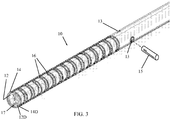
- Figs. 2 and 3 illustrate a steering tool 10.
- Steering tool 10 includes an internal tube 12 disposed inside an external tube 14.
- a distal end 12D of internal tube 12 is fixedly joined to a distal end 14D of external tube 14.
- the term “joined” encompasses any method for attaching the materials of the tubes together, such as but not limited to, welding, ultrasonic welding, thermal bonding, adhesive bonding, molding, and others.
- the internal and external tubes 12 and 14 are arranged for longitudinal axial movement relative to one another (except for their distal ends which are joined together).
- Internal tube 12 and external tube 14 are each formed with one or more alignment holes 13 for correct alignment (including axial and rotational alignment about the longitudinal axis) of the tubes during joining and assembly.
- An alignment pin 15 ( Fig. 3 ) may be inserted in alignment holes 13 to hold the tubes in the proper alignment during joining.
- the alignment holes 13 may be off-center and/or of two different diameters to ensure that the tubes are not accidentally aligned incorrectly.
- the outer diameter of internal tube 12 is smaller than the inner diameter of external tube 14 so they can easily slide relative to each other. This difference in diameter may pose a problem during welding or other types of joining.
- an open-ended axial slot 17 (also seen in the flattened view of Fig. 1 ) is formed in internal tube 12 and/or external tube 14. Slot 17 provides a path for welding, soldering or adhesive material to flow and join the tubes together.
- Internal and external tubes 12 and 14 may be made of any suitably flexible, medically safe material, such as but not limited to, stainless steel (e.g., AISI 316), nitinol, cobalt-chromium alloy, nickel-titanium alloy, and others, glass fibers, plastics (e.g., nylon, polypropylene, and many others) or combinations thereof.
- stainless steel e.g., AISI 316
- nitinol nitinol
- cobalt-chromium alloy e.g., cobalt-chromium alloy, nickel-titanium alloy, and others
- glass fibers e.g., polypropylene, and many others
- plastics e.g., nylon, polypropylene, and many others
- the tubes can be used for applications involving light guides, lasers, optic or electrical transfer and other uses, in addition to the mechanical function of bending.
- At least one of the internal and external tubes 12 and 14 is slotted with slots 16 near the distal end thereof (e.g., transverse to the longitudinal axis of the tubes; the term transverse encompassing any angle - not just perpendicular - which is not parallel to the longitudinal axis of the tubes).
- both tubes are slotted, but alternatively only one of the internal and external tubes is slotted and the other may be flexible but not slotted.
- the longitudinal axial movement causes bending of the distal ends of the tubes (on account of them being joined together), as is known from PCT/US2013/040691 .
- One of the internal and external tubes can be longer than the other (e.g., the internal one is longer for grasping its proximal end for pushing and pulling thereof).
- Slots 16 increase the flexibility toward the distal end of the tube or tubes for steerability of the device and controlled manipulation thereof.
- the amount of flexibility can be controlled by the number of slots, spacing therebetween, shape of the slot, angle subtended by the slot, thickness of the tube, material of the tube, and other factors. Slots 16 may subtend an arc of about 180-270°.
- the shapes of slots 16 change as a parameter of distance from the distal end.
- the slots decrease in length and width (e.g., asymptotically to a minimum size) with increased distance from the distal end.
- the bending radius remains basically constant at any distance from the distal end and the bending moment increases with increased distance from the distal end.
- Axial slot 17 may be open to the most distal slot 16.
- Fig. 7A illustrates the steering tool in a straight position
- Fig. 7B illustrates the steering tool bent to the left
- Fig. 7C illustrates the steering tool bent to the right.
- Both internal and external tubes 12 and 14 can be slotted with slots 16, wherein the inner tube slots have open ends facing in one direction, while the outer tube slots have the open ends facing in another direction 180° from each other.
- the slots of one of the tubes are spaced apart more than the slot spacing of the other tube.
- the inner or outer tube can be made such that some of the slots 16 have open ends facing in one direction, while other slots 16 have the open ends facing in another direction, such as 180° apart.
- the slots of one side of the tube are spaced apart more than the slot spacing of the other side.
- Fig. 7A also shows another option, in which some of the slots are shaped differently than others.
- the open ends of slots 16-1, 16-2, 16-3 and 16-4 are differently shaped - some are more closed than others. This means some of the slots will stop bending before others stop bending, because the open ends of the slot abut against each other in the bent position, thus serving as a hard stop to prevent further bending.
- differently shaped slots different bending effects can be achieved.
- the tubes can bend towards the open side of the slots until eventually the slots become closed or "pinched", at which point the closed slot serves as a stopper that permits no further bending. Due to the fact that one set of the slots is spaced further from each other than the slot spacing in the other set of slots, the tube can bend more in one direction than the other and can bend differently when the tube is pushed as opposed to pulled. The same effect can be achieved by different slot radii or shapes. Accordingly, in the embodiments of Figs. 7A-7C , some of slots 16 of internal and/or external tubes 12 and 14 are more bendable than other slots 16 of internal and/or external tubes 12 and 14 which are less bendable.
- Fig. 8 illustrates another example of shapes that can be achieved by varying the slots, namely, a helical shape, which may be useful for self-centering in a blood vessel or other lumen.
- the steering tool 10 may be covered with a semi-rigid or flexible sheath 18 (shown partially in broken lines in Fig. 2 ) and used as a catheter or needle.
- the internal tube 12 is a simple tube or wire with no slots.
- the internal tube 12 can serve as the conduit for delivery of fluids, light, laser, optic, cameras, illumination, electrical energy transfer (e.g., wired connections), and others, in addition to the mechanical function of bending,
- the device can be used to deliver fluids to places in a body with high accuracy, such as but not limited to, direct injection of drugs into the brain.
- tool 10 may be used as a needle to protrude through or into a blood vessel and inject substances directly into the brain, tumor or infected area.
- the steering tool 10 may be used as a catheter to direct and deliver cooled gas to freeze tumors or other areas.
- the steering tool 10 may be used as a catheter to guide fiber optic or laser devices for illumination, treatment, ablation or drying or other uses.
- the fiber optic can be part of the mechanical steering system, serving as a pull wire inside the internal or external tube. In this manner, a controlled fiber optic with a diameter of 0.3 mm becomes feasible.
- the distal edge shape of the internal tube, external tube and/or overall tool may be not only circular, but also shaped as an electrode, needle or other shapes.
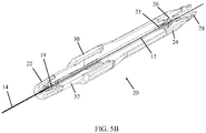
- FIG. 5A and 5B illustrate a steering tool with a manipulation handle 20, constructed and operative in accordance with a non-limiting embodiment of the present invention.
- the proximal end 19 of the external tube 14 is affixed or locked in an external tube holder 22 at the distal end of the handle 20.
- the internal tube 12 is disposed in external tube 14 as described above.
- the internal tube 12 extends through the length of handle 20, and a proximal portion 23 of internal tube 12 may be held by a proximal internal tube holder 24.
- the internal tube holder 24 may include a septum 26 which may be used to seal passage of the internal tube 12 therethrough.
- the handle 20 may be provided with a proximal fluid connector 28.
- the handle 20 is provided with a tube manipulator 30, such as a linear slider, for causing relative axial movement of the internal and external tubes.
- the tube manipulator 30 may abut against or be connected to a movable portion 32 of handle 20, which is connected to or abuts against the external tube holder 22.
- the movable portion 32 By moving tube manipulator 30 distally, the movable portion 32 also moves distally and causes the internal tube 12 to move distally as well, thereby causing bending of the distal tip of the internal and external tubes, as described above.
- the tube manipulator 30 may abut proximally against a stationary portion of the handle 20 and/or may "click" into a groove formed in the handle, which serves as a proximal stop and locks the tube manipulator 30 in place.
- the tube manipulator 30 may be released when desired from the locked position and relocked in place. There is free movement during insertion (handle unlocked) of the steering tool into the body lumen, so that both tubes can move freely and allow the steering tool to bend in accordance with the shape of the body lumen (such as any kind of curved path). After reaching the desired destination in the body lumen, the handle is locked for no more bending.
- the steering tool can be used very easily as a guide wire for guiding catheters and other devices.
- FIGs. 5C-5E illustrate a steering tool 200 with a manipulation handle 202, constructed and operative in accordance with another non-limiting embodiment of the present invention.
- This embodiment may be used with any of the internal and external tubes described in the other embodiments.
- the internal tube 12 and the external tube 14 are held in a manipulation handle that can axially move one of the tubes with respect to the other tube along their longitudinal axes to cause bending of the common distal tips of the tubes.
- the embodiment of Figs. 5C-5E differs from the previous embodiment, in that the internal tube 12 and the external tube 14 are held in a manipulation handle that additionally rotates one of the tubes with respect to the other tube around their longitudinal axes. This twists one of the tubes with respect to the other tube and causes the tubes to take on a bent or twisted shape not achievable with the previous handle.
- the tubes can take on an S-bend shape, helical shape and many other curved and twisted shapes. (It is possible to generate the phase shift by rotating the tubes and/or by cutting the slots with phase shift; in any case the bending shape occurs with the axial movement.)
- the user can twist the tubes as desired and the tool allows locking or otherwise maintaining the tubes at the selected twisted orientation.
- the description that follows is for the illustrated embodiment, but the principles of this embodiment can be carried out with other configurations and structures.
- the proximal end of the external tube 14 is affixed or locked in an external tube holder 204 at the distal end of the handle 202.
- the external tube holder 204 has fasteners 206 (e.g., pins, screws or the like) that pass through a distal hub 208 and clamp on the outside contour of external tube 14.
- Hub 208 axially extends from a drum 210 housed inside external tube holder 204.
- the external tube holder 204, together with hub 208 and drum 210, rotates around the longitudinal axis 217 of the tool.
- the proximal face of drum 210 interfaces with a disc 212 by means of catches, such as detents 214 that selectively sit in grooves 216.
- catches such as detents 214 that selectively sit in grooves 216.
- the detents get caught in the grooves ("click" into the grooves). In this manner, the user can twist the tubes as desired and the detents lock or otherwise maintain the tubes at the selected twisted orientation.
- the internal tube 12 is disposed in external tube 14 as described above.
- the internal tube 12 extends through the external tube holder 204 and is fixed or held by a proximal internal tube holder 218.
- Disc 212 is fixedly connected to or part of internal tube holder 218.
- the handle 202 is provided with a tube manipulator 220 for causing relative axial movement of the internal and external tubes.
- the tube manipulator 220 may be a sleeve 222 attached to internal tube holder 218.
- Sleeve 222 may be threadedly connected with external tube holder 204.
- a guide pin 224 may be provided that slides in a guide slot 226, for guiding axial movement of the tube.
- the proximal end of the tool may have an inlet opening 228 for passing guidewires, optical fibers or other tools through the tubes.
- open-ended axial slot 17 is formed in internal tube 12 and/or external tube 14.
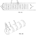
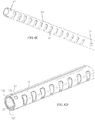
- Figs. 6A-6D illustrate another way to join internal and external tubes 12 and 14.
- external tube 14 is formed with apertures 67, which may be round holes (as in the illustrated embodiment) or may be openings of any size and shape, such as elongate slots, oval cutouts, diamond-shaped cutouts and more.
- Fig. 6A shows external tube 14 in a flattened form.
- Figs. 6B and 6C both show external tube 14 in its rolled, tubular form.
- Fig. 6D illustrates internal tube 12 joined to external tube 14.
- the welding e.g., laser welding in metal tubes
- bonding e.g., adhesive or thermal in plastic tubes
- internal tube 12 may be rolled from a flat sheet so that it has edges 12A and 12B which are close to or abut each other.
- Apertures 67 may be advantageously located near edges 12A and 12B, that is, on both sides of the cut internal tube 12. Joining the tubes at this position of the apertures helps prevent the edges 12A and 12B from springing back away from each other.
- the stiffer side of the internal tube 12 opposite the junction of the edges 12A and 12B (designated 12C in Fig.
- Apertures 67 of external tube 14 are located near the stiffest and the most flexible areas of the internal tube (12A, 12B and 12C) in order to transfer shear forces but not in between them were torque exists.
- the assembly of the inner and outer tubes can operate without connecting/welding or bonding the ends of the tubes to one another.
- one of the tubes can be made with a distal stopper at its distal end.
- the second tube can slide relative to the first tube until the second tube abuts the distal stopper of the first tube and then further application of force causes the tubes to bend as described above.
- Such a construction is very efficient for one-sided bending. Unlike the examples which have the tubes affixed to each other at the distal portions, this example will work only when pushing one of the tubes towards the distal end but will not work for pulling the tube proximally.
Landscapes
- Health & Medical Sciences (AREA)
- Life Sciences & Earth Sciences (AREA)
- Biophysics (AREA)
- Pulmonology (AREA)
- Engineering & Computer Science (AREA)
- Anesthesiology (AREA)
- Biomedical Technology (AREA)
- Heart & Thoracic Surgery (AREA)
- Hematology (AREA)
- Animal Behavior & Ethology (AREA)
- General Health & Medical Sciences (AREA)
- Public Health (AREA)
- Veterinary Medicine (AREA)
- Media Introduction/Drainage Providing Device (AREA)
Claims (14)
- Outil de pilotage (10,200) comprenant :un tube interne (12) disposé à l'intérieur d'un tube externe (14), lesdits tubes interne et externe (12, 14) étant disposés de manière à exécuter un mouvement axial longitudinal l'un par rapport à l'autre, une extrémité distale dudit tube interne (12) étant assemblée fixement à une extrémité distale dudit tube externe (14), et au moins un desdits tubes interne et externe (12, 14) étant conformé avec des fentes transversales (16) près de son extrémité distale, et le mouvement axial longitudinal provoquant la pliure des extrémités distales desdits tubes ;lesdits tubes interne et externe (12, 14) étant respectivement maintenus dans des supports de tubes interne et externe (218, 204; 22, 24) qui sont montés dans une poignée de manipulation (20, 202), et lesdits supports de tubes interne et externe (218, 204; 22, 24) étant mobiles axialement l'un par rapport à l'autre le long de leurs axes longitudinaux pour provoquer la pliure des extrémités distales desdits tubes, et lesdits supports de tubes interne et externe (218, 204; 22,24) pouvant tourner l'un par rapport à l'autre autour de leurs axes longitudinaux ; ladite poignée (20) étant pourvue d'un manipulateur de tube (30) pour provoquer un mouvement axial relatif desdits tubes interne et externe (12, 14), ledit manipulateur de tubes (30) butant contre ou étant connecté à une partie mobile (32) de ladite poignée (20) qui est connectée au ou bute contre ledit support de tube et externe (22), et ledit manipulateur de tube (30) étant conçu pour buter au niveau proximal contre une section stationnaire de ladite poignée (20), caractérisé en ce que ledit manipulateur de tube (30) est conçu pour interagir sélectivement avec une gorge pratiquée dans ladite poignée (2), ladite gorge étant apte à servir d'arrêt proximal dans ladite poignée (20) et à bloquer ledit manipulateur de tube (30) en place.
- Outil de pilotage (10, 200) selon la revendication 1, dans lequel ledit support de tube externe (204) est en interface avec ledit support de tube interne (218) par des crochets (214, 216) qui maintiennent lesdits tubes interne et externe (12, 14) dans une orientation en torsion sélectionnée.
- Outil de pilotage (10, 200) selon la revendication 1, dans lequel une extrémité proximale de l'outil comporte une ouverture d'entrée (228) pour y faire passer des outils.
- Outil de pilotage (10, 200) selon la revendication 1, dans lequel certaines desdites fentes (16) desdits au moins un tubes interne et externe (12, 14) sont plus pliables que d'autres fentes (16) desdits au moins un tubes interne et externe (12, 14) qui sont moins pliables.
- Outil de pilotage (10, 200) selon la revendication 1, dans lequel lesdites fentes (16) qui sont moins pliables butent contre un arrêt (16) qui empêche de plier davantage les fentes (16).
- Outil de pilotage (10, 200) selon la revendication I, dans lequel lesdits au moins un tubes interne et externe (12, 14) se plient différemment quand ils sont poussés par opposition à quand ils sont tirés.
- Outil de pilotage (10, 200) selon la revendication 1, dans lequel certaines desdites fentes (16) desdits au moins un tubes interne et externe (12, 14) ont des extrémités ouvertes tournées dans un sens, alors que d'autres fentes (16) desdits au moins un tubes interne et externe (12, 14) ont des extrémités ouvertes tournées dans un autre sens, les fentes (16) d'une face desdits au moins un tubes interne et externe (12, 14) étant plus espacées que les fentes (16) d'une autre face desdits au moins un tubes interne et externe (12, 14).
- Outil de pilotage (10, 200) selon la revendication I, dans lequel ledit tube externe (14) est réalisé avec des ouvertures (67) pour l'assembler audit tube interne (12).
- Outil de pilotage (10, 200) selon la revendication 8, dans lequel lesdites ouvertures (67) sont situées près des zones les plus rigides et les plus flexibles dudit tube interne (12A, 12B et 12C).
- Outil de pilotage (10, 200) selon la revendication 1, dans lequel certaines desdites fentes (16) desdits au moins un tubes interne et externe (12, 14) ont des extrémités ouvertes tournées dans un sens, alors que d'autres fentes (16) desdits au moins un tubes interne et externe (12, 14) ont des extrémités ouvertes tournées dans un autre sens, les fentes (16) d'une face desdits au moins un tubes interne et externe (12, 14) étant plus espacées que les fentes (16) d'une autre face desdits au moins un tubes interne et externe (12, 14).
- Outil de pilotage (10, 200) selon la revendication 10, dans lequel ledit tube externe (14) est réalisé avec des ouvertures (67) pour l'assembler audit tube interne (12).
- Outil de pilotage (10, 200) selon la revendication 11, dans lequel lesdites ouvertures (67) sont situées près des zones les plus rigides et les plus flexibles dudit tube interne (12A, 12B et 12C).
- Outil de pilotage (10, 200) selon la revendication 1, dans lequel ledit support de tube interne (24) comprend un septum (26) pour colmater le passage dudit tube interne (12) à travers celui-ci.
- Outil de pilotage (10, 200) selon la revendication 1, dans lequel ladite poignée (20) comprend un connecteur proximal de fluide (28).
Applications Claiming Priority (2)
| Application Number | Priority Date | Filing Date | Title |
|---|---|---|---|
| US201361918073P | 2013-12-19 | 2013-12-19 | |
| PCT/US2014/071075 WO2015095475A1 (fr) | 2013-12-19 | 2014-12-18 | Outil de pilotage |
Publications (2)
| Publication Number | Publication Date |
|---|---|
| EP3082932A1 EP3082932A1 (fr) | 2016-10-26 |
| EP3082932B1 true EP3082932B1 (fr) | 2018-01-31 |
Family
ID=52395176
Family Applications (1)
| Application Number | Title | Priority Date | Filing Date |
|---|---|---|---|
| EP14830437.1A Active EP3082932B1 (fr) | 2013-12-19 | 2014-12-18 | Outil de pilotage |
Country Status (5)
| Country | Link |
|---|---|
| US (1) | US20160310702A1 (fr) |
| EP (1) | EP3082932B1 (fr) |
| JP (1) | JP6653056B2 (fr) |
| CN (1) | CN105992605B (fr) |
| WO (1) | WO2015095475A1 (fr) |
Families Citing this family (45)
| Publication number | Priority date | Publication date | Assignee | Title |
|---|---|---|---|---|
| US12220538B2 (en) | 2008-12-08 | 2025-02-11 | Scientia Vascular, Inc. | Micro-fabricated intravascular devices having varying diameters |
| US10149720B2 (en) * | 2013-03-08 | 2018-12-11 | Auris Health, Inc. | Method, apparatus, and a system for facilitating bending of an instrument in a surgical or medical robotic environment |
| US10350066B2 (en) * | 2015-08-28 | 2019-07-16 | Edwards Lifesciences Cardiaq Llc | Steerable delivery system for replacement mitral valve and methods of use |
| US12465339B2 (en) | 2016-03-01 | 2025-11-11 | Bendit Technologies Ltd. | Steering tool with controlled distal flexibility |
| US10390814B2 (en) | 2016-04-20 | 2019-08-27 | Medos International Sarl | Meniscal repair devices, systems, and methods |
| US11000265B1 (en) * | 2016-06-20 | 2021-05-11 | Intelligent Fiber Optic Systems, Inc. | Steerable biopsy needle with fiber-activated shape memory alloy |
| US9918705B2 (en) | 2016-07-07 | 2018-03-20 | Brian Giles | Medical devices with distal control |
| US10391274B2 (en) | 2016-07-07 | 2019-08-27 | Brian Giles | Medical device with distal torque control |
| US11207502B2 (en) | 2016-07-18 | 2021-12-28 | Scientia Vascular, Llc | Guidewire devices having shapeable tips and bypass cuts |
| US11141566B2 (en) * | 2016-11-06 | 2021-10-12 | Bendit Technologies Ltd. | Steering tool |
| CN110325122B (zh) * | 2017-02-28 | 2024-03-19 | 波士顿科学国际有限公司 | 铰接针 |
| CN110691626B (zh) | 2017-05-26 | 2022-03-18 | 血管科学有限责任公司 | 具有非螺旋切口布置的微制造医疗装置 |
| US20190111237A1 (en) * | 2017-10-18 | 2019-04-18 | Bendit Technologies Ltd. | Changing catheter into steering tool |
| US10456556B2 (en) * | 2018-02-19 | 2019-10-29 | Bendit Technologies Ltd. | Steering tool with enhanced flexibility and trackability |
| US12011555B2 (en) | 2019-01-15 | 2024-06-18 | Scientia Vascular, Inc. | Guidewire with core centering mechanism |
| US20220392065A1 (en) | 2020-01-07 | 2022-12-08 | Cleerly, Inc. | Systems, methods, and devices for medical image analysis, diagnosis, risk stratification, decision making and/or disease tracking |
| US11969280B2 (en) | 2020-01-07 | 2024-04-30 | Cleerly, Inc. | Systems, methods, and devices for medical image analysis, diagnosis, risk stratification, decision making and/or disease tracking |
| JP2023509514A (ja) | 2020-01-07 | 2023-03-08 | クリールリー、 インコーポレーテッド | 医用画像分析、診断、重症度分類、意思決定、および/または疾患追跡のためのシステム、方法、およびデバイス |
| US12178975B2 (en) | 2020-01-23 | 2024-12-31 | Scientia Vascular, Inc. | Guidewire having enlarged, micro-fabricated distal section |
| US12343485B2 (en) | 2020-01-23 | 2025-07-01 | Scientia Vascular, Inc. | High torque guidewire device |
| JP2023526171A (ja) * | 2020-04-08 | 2023-06-21 | ベクトン・ディキンソン・アンド・カンパニー | アクセスセットを含む操縦可能なカニューレおよびヒンジ付きまたは操縦可能なニードルおよびその方法 |
| US12296112B2 (en) | 2020-10-05 | 2025-05-13 | Scientia Vascular, Inc. | Microfabricated catheter devices with high axial strength |
| US12446979B2 (en) | 2022-08-01 | 2025-10-21 | Imperative Care, Inc. | Method of performing a multi catheter robotic neurovascular procedure |
| US12564458B2 (en) | 2022-08-01 | 2026-03-03 | Imperative Care, Inc. | Method of robotically driving a multi catheter assembly above the aortic arch |
| US12564414B2 (en) | 2022-08-01 | 2026-03-03 | Imperative Care, Inc. | Method of supra-aortic access for a neurovascular procedure |
| US12419703B2 (en) | 2022-08-01 | 2025-09-23 | Imperative Care, Inc. | Robotic drive system for achieving supra-aortic access |
| US12447317B2 (en) | 2022-08-01 | 2025-10-21 | Imperative Care, Inc. | Method of priming concentrically stacked interventional devices |
| US12440289B2 (en) | 2022-08-01 | 2025-10-14 | Imperative Care, Inc. | Method of priming an interventional device assembly |
| US20230048388A1 (en) | 2021-08-12 | 2023-02-16 | Imperative Care, Inc. | Robotically driven interventional device |
| EP4395680A4 (fr) * | 2021-10-05 | 2025-08-13 | Siemens Healthineers Endovascular Robotics Inc | Actionnement robotique de dispositifs médicaux allongés |
| US12406365B2 (en) | 2022-03-10 | 2025-09-02 | Cleerly, Inc. | Systems, devices, and methods for non-invasive image-based plaque analysis and risk determination |
| US20250217981A1 (en) | 2022-03-10 | 2025-07-03 | Cleerly, Inc. | Systems, methods, and devices for image-based plaque analysis and risk determination |
| US12440180B2 (en) | 2022-03-10 | 2025-10-14 | Cleerly, Inc. | Systems, devices, and methods for non-invasive image-based plaque analysis and risk determination |
| US20250143657A1 (en) | 2022-03-10 | 2025-05-08 | Cleerly, Inc. | Systems, devices, and methods for non-invasive image-based plaque analysis and risk determination |
| US20240041480A1 (en) | 2022-08-02 | 2024-02-08 | Imperative Care, Inc. | Multi catheter system with integrated fluidics management |
| CN120529878A (zh) | 2022-12-01 | 2025-08-22 | 因普瑞缇夫护理公司 | 伸缩驱动台及使用方法 |
| JP2026500623A (ja) | 2022-12-01 | 2026-01-08 | インペラティブ ケア インコーポレイテッド | ロボットカテーテル駆動システムのための座屈防止デバイス |
| CN120916725A (zh) | 2022-12-01 | 2025-11-07 | 因普瑞缇夫护理公司 | 用于机器人化导管驱动系统的控制器 |
| US12377206B2 (en) | 2023-05-17 | 2025-08-05 | Imperative Care, Inc. | Fluidics control system for multi catheter stack |
| WO2024249670A2 (fr) | 2023-05-31 | 2024-12-05 | Imperative Care, Inc. | Couplage magnétique à travers une barrière de champ stérile |
| CN117138201A (zh) * | 2023-07-28 | 2023-12-01 | 上海思迪希医疗科技有限公司 | 可调弯装置 |
| USD1102447S1 (en) | 2023-11-30 | 2025-11-18 | Imperative Care, Inc. | Display screen or portion thereof with graphical user interface |
| USD1119865S1 (en) | 2023-11-30 | 2026-03-24 | Imperative Care, Inc. | Controller |
| CN118022138B (zh) * | 2024-02-03 | 2024-07-23 | 谱高医疗科技(南京)有限公司 | 一种可调弯微导管手柄 |
| WO2025205999A1 (fr) * | 2024-03-28 | 2025-10-02 | 日本ゼオン株式会社 | Dispositif médical et dispositif d'opération de déviation pour équipement médical |
Family Cites Families (23)
| Publication number | Priority date | Publication date | Assignee | Title |
|---|---|---|---|---|
| US5833632A (en) * | 1995-12-07 | 1998-11-10 | Sarcos, Inc. | Hollow guide wire apparatus catheters |
| US6030360A (en) * | 1996-12-30 | 2000-02-29 | Biggs; Robert C. | Steerable catheter |
| US5873817A (en) * | 1997-05-12 | 1999-02-23 | Circon Corporation | Endoscope with resilient deflectable section |
| US5941849A (en) * | 1997-08-29 | 1999-08-24 | Scimed Life Systems, Inc. | Suture retention device |
| US5916147A (en) * | 1997-09-22 | 1999-06-29 | Boury; Harb N. | Selectively manipulable catheter |
| US6059739A (en) * | 1998-05-29 | 2000-05-09 | Medtronic, Inc. | Method and apparatus for deflecting a catheter or lead |
| US7381198B2 (en) * | 2000-08-23 | 2008-06-03 | Revascular Therapeutics, Inc. | Steerable distal support system |
| US7481778B2 (en) * | 2002-03-22 | 2009-01-27 | Cordis Corporation | Guidewire with deflectable tip having improved flexibility |
| US7128718B2 (en) * | 2002-03-22 | 2006-10-31 | Cordis Corporation | Guidewire with deflectable tip |
| ATE452676T1 (de) * | 2005-04-07 | 2010-01-15 | Creganna Technologies Ltd | Lenkbare katheteranordnung |
| US8096985B2 (en) * | 2008-05-07 | 2012-01-17 | Guided Delivery Systems Inc. | Deflectable guide |
| WO2010129075A1 (fr) * | 2009-04-28 | 2010-11-11 | Avinger, Inc. | Cathéter de support de fil-guide |
| DE102009042490A1 (de) * | 2009-05-29 | 2010-12-09 | Aesculap Ag | Steuerungsvorrichtung |
| US9039676B2 (en) * | 2009-06-11 | 2015-05-26 | St. Jude Medical Puerto Rico Llc | Apparatus and methods for catheter steerability |
| US8323241B2 (en) * | 2009-06-24 | 2012-12-04 | Shifamed Holdings, Llc | Steerable medical delivery devices and methods of use |
| US20110071490A1 (en) * | 2009-09-18 | 2011-03-24 | Kassab Interventional Devices, Llc ("Kids") | System and procedure for placing a medical device proximate an ostial lesion using a catheter assembly |
| CN102413863A (zh) * | 2009-10-14 | 2012-04-11 | 奥林巴斯医疗株式会社 | 医疗用挠性管和医疗设备的插入部 |
| US10232150B2 (en) * | 2010-03-11 | 2019-03-19 | Merit Medical Systems, Inc. | Body cavity drainage devices and related methods |
| US9144665B2 (en) * | 2010-08-09 | 2015-09-29 | Boston Scientific Limited | Flexible sheath assemblies and interventional catheter systems incorporating them |
| CN103764216B (zh) * | 2011-05-03 | 2016-08-17 | 施菲姆德控股有限责任公司 | 可转向输送护套 |
| WO2013016616A2 (fr) * | 2011-07-27 | 2013-01-31 | The University Of Kansas | Tube d'alimentation nasoentérique manoeuvrable |
| US9233225B2 (en) * | 2012-11-10 | 2016-01-12 | Curvo Medical, Inc. | Coaxial bi-directional catheter |
| US9339271B2 (en) * | 2013-03-14 | 2016-05-17 | C.R. Bard, Inc. | Articulating surgical instruments |
-
2014
- 2014-12-18 WO PCT/US2014/071075 patent/WO2015095475A1/fr not_active Ceased
- 2014-12-18 CN CN201480068948.9A patent/CN105992605B/zh active Active
- 2014-12-18 US US15/104,316 patent/US20160310702A1/en not_active Abandoned
- 2014-12-18 EP EP14830437.1A patent/EP3082932B1/fr active Active
- 2014-12-18 JP JP2016538726A patent/JP6653056B2/ja active Active
Also Published As
| Publication number | Publication date |
|---|---|
| JP6653056B2 (ja) | 2020-02-26 |
| EP3082932A1 (fr) | 2016-10-26 |
| CN105992605A (zh) | 2016-10-05 |
| CN105992605B (zh) | 2019-11-05 |
| US20160310702A1 (en) | 2016-10-27 |
| JP2017508486A (ja) | 2017-03-30 |
| WO2015095475A1 (fr) | 2015-06-25 |
Similar Documents
| Publication | Publication Date | Title |
|---|---|---|
| EP3082932B1 (fr) | Outil de pilotage | |
| US12397133B2 (en) | Steering tool | |
| US9138566B2 (en) | Steering tool | |
| US8684953B2 (en) | Steering tool | |
| JP4152546B2 (ja) | 二方向電極カテーテル | |
| CN110035791B (zh) | 操纵工具 | |
| US5108368A (en) | Steerable medical device | |
| EP1723981B1 (fr) | Cathéter orientable avec des gaines d'orientation dans l'embout distal | |
| JP4675686B2 (ja) | 二方向カテーテルのための改善された操縦機構 | |
| CN110913763B (zh) | 可操纵引导导管 | |
| WO2019077461A1 (fr) | Changement d'un cathéter en un outil d'orientation | |
| CN102665573B (zh) | 用于在组织中形成管道的装置 | |
| EP3009162B1 (fr) | Cathéter et procédé pour sa fabrication | |
| JP2007181689A (ja) | デュアルレバー双方向ハンドル | |
| WO2014162440A1 (fr) | Élément d'actionnement et dispositif médical | |
| CN209885000U (zh) | 可调弯导管 | |
| EP3490428B1 (fr) | Manche de cathéter orientable | |
| CN115400331A (zh) | 导丝组件和静脉导管装置 | |
| EP4729010A1 (fr) | Tube de guidage métallique |
Legal Events
| Date | Code | Title | Description |
|---|---|---|---|
| PUAI | Public reference made under article 153(3) epc to a published international application that has entered the european phase |
Free format text: ORIGINAL CODE: 0009012 |
|
| 17P | Request for examination filed |
Effective date: 20160629 |
|
| AK | Designated contracting states |
Kind code of ref document: A1 Designated state(s): AL AT BE BG CH CY CZ DE DK EE ES FI FR GB GR HR HU IE IS IT LI LT LU LV MC MK MT NL NO PL PT RO RS SE SI SK SM TR |
|
| AX | Request for extension of the european patent |
Extension state: BA ME |
|
| DAX | Request for extension of the european patent (deleted) | ||
| STAA | Information on the status of an ep patent application or granted ep patent |
Free format text: STATUS: EXAMINATION IS IN PROGRESS |
|
| 17Q | First examination report despatched |
Effective date: 20170704 |
|
| GRAP | Despatch of communication of intention to grant a patent |
Free format text: ORIGINAL CODE: EPIDOSNIGR1 |
|
| STAA | Information on the status of an ep patent application or granted ep patent |
Free format text: STATUS: GRANT OF PATENT IS INTENDED |
|
| INTG | Intention to grant announced |
Effective date: 20171004 |
|
| GRAS | Grant fee paid |
Free format text: ORIGINAL CODE: EPIDOSNIGR3 |
|
| GRAA | (expected) grant |
Free format text: ORIGINAL CODE: 0009210 |
|
| STAA | Information on the status of an ep patent application or granted ep patent |
Free format text: STATUS: THE PATENT HAS BEEN GRANTED |
|
| AK | Designated contracting states |
Kind code of ref document: B1 Designated state(s): AL AT BE BG CH CY CZ DE DK EE ES FI FR GB GR HR HU IE IS IT LI LT LU LV MC MK MT NL NO PL PT RO RS SE SI SK SM TR |
|
| REG | Reference to a national code |
Ref country code: GB Ref legal event code: FG4D Ref country code: CH Ref legal event code: EP Ref country code: CH Ref legal event code: NV Representative=s name: ROMAN VUILLE, CH |
|
| REG | Reference to a national code |
Ref country code: AT Ref legal event code: REF Ref document number: 966793 Country of ref document: AT Kind code of ref document: T Effective date: 20180215 |
|
| REG | Reference to a national code |
Ref country code: IE Ref legal event code: FG4D |
|
| REG | Reference to a national code |
Ref country code: DE Ref legal event code: R096 Ref document number: 602014020625 Country of ref document: DE |
|
| REG | Reference to a national code |
Ref country code: NL Ref legal event code: FP |
|
| REG | Reference to a national code |
Ref country code: LT Ref legal event code: MG4D |
|
| REG | Reference to a national code |
Ref country code: AT Ref legal event code: MK05 Ref document number: 966793 Country of ref document: AT Kind code of ref document: T Effective date: 20180131 |
|
| PG25 | Lapsed in a contracting state [announced via postgrant information from national office to epo] |
Ref country code: LT Free format text: LAPSE BECAUSE OF FAILURE TO SUBMIT A TRANSLATION OF THE DESCRIPTION OR TO PAY THE FEE WITHIN THE PRESCRIBED TIME-LIMIT Effective date: 20180131 Ref country code: NO Free format text: LAPSE BECAUSE OF FAILURE TO SUBMIT A TRANSLATION OF THE DESCRIPTION OR TO PAY THE FEE WITHIN THE PRESCRIBED TIME-LIMIT Effective date: 20180430 Ref country code: ES Free format text: LAPSE BECAUSE OF FAILURE TO SUBMIT A TRANSLATION OF THE DESCRIPTION OR TO PAY THE FEE WITHIN THE PRESCRIBED TIME-LIMIT Effective date: 20180131 Ref country code: HR Free format text: LAPSE BECAUSE OF FAILURE TO SUBMIT A TRANSLATION OF THE DESCRIPTION OR TO PAY THE FEE WITHIN THE PRESCRIBED TIME-LIMIT Effective date: 20180131 Ref country code: FI Free format text: LAPSE BECAUSE OF FAILURE TO SUBMIT A TRANSLATION OF THE DESCRIPTION OR TO PAY THE FEE WITHIN THE PRESCRIBED TIME-LIMIT Effective date: 20180131 |
|
| PG25 | Lapsed in a contracting state [announced via postgrant information from national office to epo] |
Ref country code: PL Free format text: LAPSE BECAUSE OF FAILURE TO SUBMIT A TRANSLATION OF THE DESCRIPTION OR TO PAY THE FEE WITHIN THE PRESCRIBED TIME-LIMIT Effective date: 20180131 Ref country code: GR Free format text: LAPSE BECAUSE OF FAILURE TO SUBMIT A TRANSLATION OF THE DESCRIPTION OR TO PAY THE FEE WITHIN THE PRESCRIBED TIME-LIMIT Effective date: 20180501 Ref country code: AT Free format text: LAPSE BECAUSE OF FAILURE TO SUBMIT A TRANSLATION OF THE DESCRIPTION OR TO PAY THE FEE WITHIN THE PRESCRIBED TIME-LIMIT Effective date: 20180131 Ref country code: RS Free format text: LAPSE BECAUSE OF FAILURE TO SUBMIT A TRANSLATION OF THE DESCRIPTION OR TO PAY THE FEE WITHIN THE PRESCRIBED TIME-LIMIT Effective date: 20180131 Ref country code: IS Free format text: LAPSE BECAUSE OF FAILURE TO SUBMIT A TRANSLATION OF THE DESCRIPTION OR TO PAY THE FEE WITHIN THE PRESCRIBED TIME-LIMIT Effective date: 20180531 Ref country code: BG Free format text: LAPSE BECAUSE OF FAILURE TO SUBMIT A TRANSLATION OF THE DESCRIPTION OR TO PAY THE FEE WITHIN THE PRESCRIBED TIME-LIMIT Effective date: 20180430 Ref country code: LV Free format text: LAPSE BECAUSE OF FAILURE TO SUBMIT A TRANSLATION OF THE DESCRIPTION OR TO PAY THE FEE WITHIN THE PRESCRIBED TIME-LIMIT Effective date: 20180131 Ref country code: SE Free format text: LAPSE BECAUSE OF FAILURE TO SUBMIT A TRANSLATION OF THE DESCRIPTION OR TO PAY THE FEE WITHIN THE PRESCRIBED TIME-LIMIT Effective date: 20180131 |
|
| PG25 | Lapsed in a contracting state [announced via postgrant information from national office to epo] |
Ref country code: RO Free format text: LAPSE BECAUSE OF FAILURE TO SUBMIT A TRANSLATION OF THE DESCRIPTION OR TO PAY THE FEE WITHIN THE PRESCRIBED TIME-LIMIT Effective date: 20180131 Ref country code: AL Free format text: LAPSE BECAUSE OF FAILURE TO SUBMIT A TRANSLATION OF THE DESCRIPTION OR TO PAY THE FEE WITHIN THE PRESCRIBED TIME-LIMIT Effective date: 20180131 Ref country code: EE Free format text: LAPSE BECAUSE OF FAILURE TO SUBMIT A TRANSLATION OF THE DESCRIPTION OR TO PAY THE FEE WITHIN THE PRESCRIBED TIME-LIMIT Effective date: 20180131 |
|
| REG | Reference to a national code |
Ref country code: DE Ref legal event code: R097 Ref document number: 602014020625 Country of ref document: DE |
|
| PG25 | Lapsed in a contracting state [announced via postgrant information from national office to epo] |
Ref country code: CZ Free format text: LAPSE BECAUSE OF FAILURE TO SUBMIT A TRANSLATION OF THE DESCRIPTION OR TO PAY THE FEE WITHIN THE PRESCRIBED TIME-LIMIT Effective date: 20180131 Ref country code: SM Free format text: LAPSE BECAUSE OF FAILURE TO SUBMIT A TRANSLATION OF THE DESCRIPTION OR TO PAY THE FEE WITHIN THE PRESCRIBED TIME-LIMIT Effective date: 20180131 Ref country code: DK Free format text: LAPSE BECAUSE OF FAILURE TO SUBMIT A TRANSLATION OF THE DESCRIPTION OR TO PAY THE FEE WITHIN THE PRESCRIBED TIME-LIMIT Effective date: 20180131 Ref country code: SK Free format text: LAPSE BECAUSE OF FAILURE TO SUBMIT A TRANSLATION OF THE DESCRIPTION OR TO PAY THE FEE WITHIN THE PRESCRIBED TIME-LIMIT Effective date: 20180131 |
|
| PLBE | No opposition filed within time limit |
Free format text: ORIGINAL CODE: 0009261 |
|
| STAA | Information on the status of an ep patent application or granted ep patent |
Free format text: STATUS: NO OPPOSITION FILED WITHIN TIME LIMIT |
|
| 26N | No opposition filed |
Effective date: 20181102 |
|
| PG25 | Lapsed in a contracting state [announced via postgrant information from national office to epo] |
Ref country code: SI Free format text: LAPSE BECAUSE OF FAILURE TO SUBMIT A TRANSLATION OF THE DESCRIPTION OR TO PAY THE FEE WITHIN THE PRESCRIBED TIME-LIMIT Effective date: 20180131 |
|
| PG25 | Lapsed in a contracting state [announced via postgrant information from national office to epo] |
Ref country code: MC Free format text: LAPSE BECAUSE OF FAILURE TO SUBMIT A TRANSLATION OF THE DESCRIPTION OR TO PAY THE FEE WITHIN THE PRESCRIBED TIME-LIMIT Effective date: 20180131 Ref country code: LU Free format text: LAPSE BECAUSE OF NON-PAYMENT OF DUE FEES Effective date: 20181218 |
|
| REG | Reference to a national code |
Ref country code: BE Ref legal event code: MM Effective date: 20181231 |
|
| PG25 | Lapsed in a contracting state [announced via postgrant information from national office to epo] |
Ref country code: BE Free format text: LAPSE BECAUSE OF NON-PAYMENT OF DUE FEES Effective date: 20181231 |
|
| PG25 | Lapsed in a contracting state [announced via postgrant information from national office to epo] |
Ref country code: MT Free format text: LAPSE BECAUSE OF NON-PAYMENT OF DUE FEES Effective date: 20181218 |
|
| PG25 | Lapsed in a contracting state [announced via postgrant information from national office to epo] |
Ref country code: PT Free format text: LAPSE BECAUSE OF FAILURE TO SUBMIT A TRANSLATION OF THE DESCRIPTION OR TO PAY THE FEE WITHIN THE PRESCRIBED TIME-LIMIT Effective date: 20180131 |
|
| PG25 | Lapsed in a contracting state [announced via postgrant information from national office to epo] |
Ref country code: CY Free format text: LAPSE BECAUSE OF FAILURE TO SUBMIT A TRANSLATION OF THE DESCRIPTION OR TO PAY THE FEE WITHIN THE PRESCRIBED TIME-LIMIT Effective date: 20180131 Ref country code: MK Free format text: LAPSE BECAUSE OF NON-PAYMENT OF DUE FEES Effective date: 20180131 Ref country code: HU Free format text: LAPSE BECAUSE OF FAILURE TO SUBMIT A TRANSLATION OF THE DESCRIPTION OR TO PAY THE FEE WITHIN THE PRESCRIBED TIME-LIMIT; INVALID AB INITIO Effective date: 20141218 |
|
| PG25 | Lapsed in a contracting state [announced via postgrant information from national office to epo] |
Ref country code: TR Free format text: LAPSE BECAUSE OF FAILURE TO SUBMIT A TRANSLATION OF THE DESCRIPTION OR TO PAY THE FEE WITHIN THE PRESCRIBED TIME-LIMIT Effective date: 20180131 |
|
| REG | Reference to a national code |
Ref country code: CH Ref legal event code: U11 Free format text: ST27 STATUS EVENT CODE: U-0-0-U10-U11 (AS PROVIDED BY THE NATIONAL OFFICE) Effective date: 20260101 |
|
| PGFP | Annual fee paid to national office [announced via postgrant information from national office to epo] |
Ref country code: GB Payment date: 20251218 Year of fee payment: 12 |
|
| PGFP | Annual fee paid to national office [announced via postgrant information from national office to epo] |
Ref country code: FR Payment date: 20251218 Year of fee payment: 12 Ref country code: NL Payment date: 20251217 Year of fee payment: 12 |
|
| PGFP | Annual fee paid to national office [announced via postgrant information from national office to epo] |
Ref country code: TR Payment date: 20251212 Year of fee payment: 12 |
|
| PGFP | Annual fee paid to national office [announced via postgrant information from national office to epo] |
Ref country code: IE Payment date: 20251218 Year of fee payment: 12 |
|
| PGFP | Annual fee paid to national office [announced via postgrant information from national office to epo] |
Ref country code: DE Payment date: 20251210 Year of fee payment: 12 |
|
| PGFP | Annual fee paid to national office [announced via postgrant information from national office to epo] |
Ref country code: IT Payment date: 20251231 Year of fee payment: 12 |
|
| PGFP | Annual fee paid to national office [announced via postgrant information from national office to epo] |
Ref country code: CH Payment date: 20260101 Year of fee payment: 12 |