EP3083052B1 - Laminierte mikrofluidische vorrichtung mit membranventilen - Google Patents
Laminierte mikrofluidische vorrichtung mit membranventilen Download PDFInfo
- Publication number
- EP3083052B1 EP3083052B1 EP14803172.7A EP14803172A EP3083052B1 EP 3083052 B1 EP3083052 B1 EP 3083052B1 EP 14803172 A EP14803172 A EP 14803172A EP 3083052 B1 EP3083052 B1 EP 3083052B1
- Authority
- EP
- European Patent Office
- Prior art keywords
- foil
- laminated
- membrane
- flow path
- valve
- Prior art date
- Legal status (The legal status is an assumption and is not a legal conclusion. Google has not performed a legal analysis and makes no representation as to the accuracy of the status listed.)
- Active
Links
Images


Classifications
-
- B—PERFORMING OPERATIONS; TRANSPORTING
- B01—PHYSICAL OR CHEMICAL PROCESSES OR APPARATUS IN GENERAL
- B01L—CHEMICAL OR PHYSICAL LABORATORY APPARATUS FOR GENERAL USE
- B01L3/00—Containers or dishes for laboratory use, e.g. laboratory glassware; Droppers
- B01L3/50—Containers for the purpose of retaining a material to be analysed, e.g. test tubes
- B01L3/502—Containers for the purpose of retaining a material to be analysed, e.g. test tubes with fluid transport, e.g. in multi-compartment structures
- B01L3/5027—Containers for the purpose of retaining a material to be analysed, e.g. test tubes with fluid transport, e.g. in multi-compartment structures by integrated microfluidic structures, i.e. dimensions of channels and chambers are such that surface tension forces are important, e.g. lab-on-a-chip
- B01L3/502738—Containers for the purpose of retaining a material to be analysed, e.g. test tubes with fluid transport, e.g. in multi-compartment structures by integrated microfluidic structures, i.e. dimensions of channels and chambers are such that surface tension forces are important, e.g. lab-on-a-chip characterised by integrated valves
-
- B—PERFORMING OPERATIONS; TRANSPORTING
- B01—PHYSICAL OR CHEMICAL PROCESSES OR APPARATUS IN GENERAL
- B01L—CHEMICAL OR PHYSICAL LABORATORY APPARATUS FOR GENERAL USE
- B01L3/00—Containers or dishes for laboratory use, e.g. laboratory glassware; Droppers
- B01L3/50—Containers for the purpose of retaining a material to be analysed, e.g. test tubes
- B01L3/502—Containers for the purpose of retaining a material to be analysed, e.g. test tubes with fluid transport, e.g. in multi-compartment structures
- B01L3/5027—Containers for the purpose of retaining a material to be analysed, e.g. test tubes with fluid transport, e.g. in multi-compartment structures by integrated microfluidic structures, i.e. dimensions of channels and chambers are such that surface tension forces are important, e.g. lab-on-a-chip
- B01L3/502707—Containers for the purpose of retaining a material to be analysed, e.g. test tubes with fluid transport, e.g. in multi-compartment structures by integrated microfluidic structures, i.e. dimensions of channels and chambers are such that surface tension forces are important, e.g. lab-on-a-chip characterised by the manufacture of the container or its components
-
- B—PERFORMING OPERATIONS; TRANSPORTING
- B29—WORKING OF PLASTICS; WORKING OF SUBSTANCES IN A PLASTIC STATE IN GENERAL
- B29C—SHAPING OR JOINING OF PLASTICS; SHAPING OF MATERIAL IN A PLASTIC STATE, NOT OTHERWISE PROVIDED FOR; AFTER-TREATMENT OF THE SHAPED PRODUCTS, e.g. REPAIRING
- B29C45/00—Injection moulding, i.e. forcing the required volume of moulding material through a nozzle into a closed mould; Apparatus therefor
- B29C45/14—Injection moulding, i.e. forcing the required volume of moulding material through a nozzle into a closed mould; Apparatus therefor incorporating preformed parts or layers, e.g. injection moulding around inserts or for coating articles
- B29C45/14336—Coating a portion of the article, e.g. the edge of the article
- B29C45/14344—Moulding in or through a hole in the article, e.g. outsert moulding
-
- B—PERFORMING OPERATIONS; TRANSPORTING
- B32—LAYERED PRODUCTS
- B32B—LAYERED PRODUCTS, i.e. PRODUCTS BUILT-UP OF STRATA OF FLAT OR NON-FLAT, e.g. CELLULAR OR HONEYCOMB, FORM
- B32B38/00—Ancillary operations in connection with laminating processes
-
- F—MECHANICAL ENGINEERING; LIGHTING; HEATING; WEAPONS; BLASTING
- F16—ENGINEERING ELEMENTS AND UNITS; GENERAL MEASURES FOR PRODUCING AND MAINTAINING EFFECTIVE FUNCTIONING OF MACHINES OR INSTALLATIONS; THERMAL INSULATION IN GENERAL
- F16K—VALVES; TAPS; COCKS; ACTUATING-FLOATS; DEVICES FOR VENTING OR AERATING
- F16K99/00—Subject matter not provided for in other groups of this subclass
- F16K99/0001—Microvalves
- F16K99/0003—Constructional types of microvalves; Details of the cutting-off member
- F16K99/0015—Diaphragm or membrane valves
-
- B—PERFORMING OPERATIONS; TRANSPORTING
- B01—PHYSICAL OR CHEMICAL PROCESSES OR APPARATUS IN GENERAL
- B01L—CHEMICAL OR PHYSICAL LABORATORY APPARATUS FOR GENERAL USE
- B01L2200/00—Solutions for specific problems relating to chemical or physical laboratory apparatus
- B01L2200/06—Fluid handling related problems
- B01L2200/0689—Sealing
-
- B—PERFORMING OPERATIONS; TRANSPORTING
- B01—PHYSICAL OR CHEMICAL PROCESSES OR APPARATUS IN GENERAL
- B01L—CHEMICAL OR PHYSICAL LABORATORY APPARATUS FOR GENERAL USE
- B01L2200/00—Solutions for specific problems relating to chemical or physical laboratory apparatus
- B01L2200/12—Specific details about manufacturing devices
-
- B—PERFORMING OPERATIONS; TRANSPORTING
- B01—PHYSICAL OR CHEMICAL PROCESSES OR APPARATUS IN GENERAL
- B01L—CHEMICAL OR PHYSICAL LABORATORY APPARATUS FOR GENERAL USE
- B01L2300/00—Additional constructional details
- B01L2300/08—Geometry, shape and general structure
- B01L2300/0887—Laminated structure
-
- B—PERFORMING OPERATIONS; TRANSPORTING
- B01—PHYSICAL OR CHEMICAL PROCESSES OR APPARATUS IN GENERAL
- B01L—CHEMICAL OR PHYSICAL LABORATORY APPARATUS FOR GENERAL USE
- B01L2300/00—Additional constructional details
- B01L2300/12—Specific details about materials
- B01L2300/123—Flexible; Elastomeric
-
- B—PERFORMING OPERATIONS; TRANSPORTING
- B01—PHYSICAL OR CHEMICAL PROCESSES OR APPARATUS IN GENERAL
- B01L—CHEMICAL OR PHYSICAL LABORATORY APPARATUS FOR GENERAL USE
- B01L2400/00—Moving or stopping fluids
- B01L2400/06—Valves, specific forms thereof
- B01L2400/0633—Valves, specific forms thereof with moving parts
- B01L2400/0655—Valves, specific forms thereof with moving parts pinch valves
-
- B—PERFORMING OPERATIONS; TRANSPORTING
- B29—WORKING OF PLASTICS; WORKING OF SUBSTANCES IN A PLASTIC STATE IN GENERAL
- B29C—SHAPING OR JOINING OF PLASTICS; SHAPING OF MATERIAL IN A PLASTIC STATE, NOT OTHERWISE PROVIDED FOR; AFTER-TREATMENT OF THE SHAPED PRODUCTS, e.g. REPAIRING
- B29C45/00—Injection moulding, i.e. forcing the required volume of moulding material through a nozzle into a closed mould; Apparatus therefor
- B29C45/14—Injection moulding, i.e. forcing the required volume of moulding material through a nozzle into a closed mould; Apparatus therefor incorporating preformed parts or layers, e.g. injection moulding around inserts or for coating articles
- B29C45/14778—Injection moulding, i.e. forcing the required volume of moulding material through a nozzle into a closed mould; Apparatus therefor incorporating preformed parts or layers, e.g. injection moulding around inserts or for coating articles the article consisting of a material with particular properties, e.g. porous, brittle
- B29C45/14811—Multilayered articles
-
- B—PERFORMING OPERATIONS; TRANSPORTING
- B29—WORKING OF PLASTICS; WORKING OF SUBSTANCES IN A PLASTIC STATE IN GENERAL
- B29K—INDEXING SCHEME ASSOCIATED WITH SUBCLASSES B29B, B29C OR B29D, RELATING TO MOULDING MATERIALS OR TO MATERIALS FOR MOULDS, REINFORCEMENTS, FILLERS OR PREFORMED PARTS, e.g. INSERTS
- B29K2021/00—Use of unspecified rubbers as moulding material
- B29K2021/003—Thermoplastic elastomers
-
- B—PERFORMING OPERATIONS; TRANSPORTING
- B32—LAYERED PRODUCTS
- B32B—LAYERED PRODUCTS, i.e. PRODUCTS BUILT-UP OF STRATA OF FLAT OR NON-FLAT, e.g. CELLULAR OR HONEYCOMB, FORM
- B32B2250/00—Layers arrangement
- B32B2250/05—5 or more layers
-
- B—PERFORMING OPERATIONS; TRANSPORTING
- B32—LAYERED PRODUCTS
- B32B—LAYERED PRODUCTS, i.e. PRODUCTS BUILT-UP OF STRATA OF FLAT OR NON-FLAT, e.g. CELLULAR OR HONEYCOMB, FORM
- B32B2367/00—Polyesters, e.g. PET, i.e. polyethylene terephthalate
-
- B—PERFORMING OPERATIONS; TRANSPORTING
- B32—LAYERED PRODUCTS
- B32B—LAYERED PRODUCTS, i.e. PRODUCTS BUILT-UP OF STRATA OF FLAT OR NON-FLAT, e.g. CELLULAR OR HONEYCOMB, FORM
- B32B2369/00—Polycarbonates
-
- B—PERFORMING OPERATIONS; TRANSPORTING
- B32—LAYERED PRODUCTS
- B32B—LAYERED PRODUCTS, i.e. PRODUCTS BUILT-UP OF STRATA OF FLAT OR NON-FLAT, e.g. CELLULAR OR HONEYCOMB, FORM
- B32B2379/00—Other polymers having nitrogen, with or without oxygen or carbon only, in the main chain
- B32B2379/08—Polyimides
-
- F—MECHANICAL ENGINEERING; LIGHTING; HEATING; WEAPONS; BLASTING
- F16—ENGINEERING ELEMENTS AND UNITS; GENERAL MEASURES FOR PRODUCING AND MAINTAINING EFFECTIVE FUNCTIONING OF MACHINES OR INSTALLATIONS; THERMAL INSULATION IN GENERAL
- F16K—VALVES; TAPS; COCKS; ACTUATING-FLOATS; DEVICES FOR VENTING OR AERATING
- F16K99/00—Subject matter not provided for in other groups of this subclass
- F16K2099/0073—Fabrication methods specifically adapted for microvalves
- F16K2099/0078—Fabrication methods specifically adapted for microvalves using moulding or stamping
-
- F—MECHANICAL ENGINEERING; LIGHTING; HEATING; WEAPONS; BLASTING
- F16—ENGINEERING ELEMENTS AND UNITS; GENERAL MEASURES FOR PRODUCING AND MAINTAINING EFFECTIVE FUNCTIONING OF MACHINES OR INSTALLATIONS; THERMAL INSULATION IN GENERAL
- F16K—VALVES; TAPS; COCKS; ACTUATING-FLOATS; DEVICES FOR VENTING OR AERATING
- F16K99/00—Subject matter not provided for in other groups of this subclass
- F16K2099/0073—Fabrication methods specifically adapted for microvalves
- F16K2099/008—Multi-layer fabrications
-
- F—MECHANICAL ENGINEERING; LIGHTING; HEATING; WEAPONS; BLASTING
- F16—ENGINEERING ELEMENTS AND UNITS; GENERAL MEASURES FOR PRODUCING AND MAINTAINING EFFECTIVE FUNCTIONING OF MACHINES OR INSTALLATIONS; THERMAL INSULATION IN GENERAL
- F16K—VALVES; TAPS; COCKS; ACTUATING-FLOATS; DEVICES FOR VENTING OR AERATING
- F16K99/00—Subject matter not provided for in other groups of this subclass
- F16K2099/0082—Microvalves adapted for a particular use
- F16K2099/0084—Chemistry or biology, e.g. "lab-on-a-chip" technology
Definitions
- the present invention relates to a novel method of making laminated microfluidics devices with membrane valves that is useful for regulating the flow of a liquid sample through an analytical instrument such as, for example, a biosensor.
- the invention also relates to a laminated microfluidics device with membrane valves made according to such a method, as well as a method and system of using the novel laminated microfluidics device.
- a variety of analytical techniques are used to characterize interactions between molecules, particularly in the context of assays directed to the detection and interaction of biomolecules.
- antibody-antigen interactions are of fundamental importance in many fields, including biology, immunology and pharmacology.
- many analytical techniques involve binding of a "ligand”, such as an antibody, to a solid support, followed by contacting the ligand with an "analyte”, such as an antigen. Following contact of the ligand and analyte, some characteristic is measured which is indicative of the interaction, such as the ability of the ligand to bind the analyte.
- Analytical sensor systems that can monitor such molecular interactions in real time are gaining increasing interest. These systems are often based on optical biosensors and usually referred to as interaction analysis sensors or biospecific interaction analysis sensors.
- a representative biosensor system is the Biacore® instrumentation sold by GE Healthcare Life Sciences, which uses surface plasmon resonance (SPR) for detecting interactions between molecules in a sample and molecular structures immobilized on a sensing surface.
- SPR surface plasmon resonance
- the integrated microfluidic cartridge is a key part in the Biacore instruments.
- the current IFC is costly to produce and the moulds needed are time consuming to make. Because of the thickness of the injection moulded plates, dead volume of via-holes are rather big.
- US patent 6,698,454 describes a new valve design for an IFC with a minimum of silicone rubber (or other elastomer) moulding, compared to the IFC on the market with in silicone rubber flow channels and valves. However, an IFC incorporating such a design has not been introduced onto the market.
- Laminated foil microfluidic channels/reactors are available from Takasago Electric, Japan. These are combined with micro-solenoid valves as complete microfluidic devices. Method of making laminated microfluidic structures have also been described before.
- Various adhesives and strong organic solvents have been used for laminating together polymeric material.
- US20080178987A1 describes a method that used weak organic material (e.g., acetonitrile) instead of strong organic solvents or adhesives to laminate.
- US 5932799 describes adhesiveless bonding of polyimide films for the generation of microfluidic modules. There, a flexible polymer layer is bonded to the microchannel layers to serve as valves.
- An exemplary valve layer is given as composed of DuPont's Kapton® KJ thermoplastic polyimide film, with a preferred thickness of about 1 mil.
- Prior art includes US6698454 .
- the present invention discloses a novel method of making a laminated microfluidics device with membrane valves that is useful for regulating the flow of a liquid sample through an analytical instrument such as, for example, a biosensor.
- the present invention further discloses a laminated microfluidics device with membrane valves made according to such a method.
- the term 'microfluidics' is used as a noun for brevity, and should be read as 'micro fluidics device' or similar.
- a first aspect of the present invention is to provide a method for making a laminated microfluidics device including membrane valves according to claim 1.
- the present invention relates to a novel method of making laminated micro fluidics with membrane valves that is useful for regulating the flow of a liquid sample through an analytical instrument such as, for example, a biosensor, as well as the laminated microfluidics with membrane valves made according to the method.
- biosensors are analytical devices for analyzing minute quantities of sample solution having an analyte of interest, wherein the analyte is analyzed by a detection device that may employ a variety of detection methods.
- detection methods include, but are not limited to, mass detection methods, such as piezoelectric, optical, thermo-optical and surface acoustic wave (SAW) device methods, and electrochemical methods, such as potentiometric, conductometric, amperometric and capacitance methods.
- mass detection methods such as piezoelectric, optical, thermo-optical and surface acoustic wave (SAW) device methods
- electrochemical methods such as potentiometric, conductometric, amperometric and capacitance methods.
- representative methods include those that detect mass surface concentration, such as reflection-optical methods, including both internal and external reflection methods, angle, wavelength or phase resolved, for example ellipsometry and evanescent wave spectroscopy (EWS), the latter including surface plasmon resonance (SPR) spectroscopy, Brewster angle refractometry, critical angle refractometry, frustrated total reflection (FTR), evanescent wave ellipsometry, scattered total internal reflection (STIR), optical wave guide sensors, evanescent wave-based imaging, such as critical angle resolved imaging, Brewster angle resolved imaging, SPR angle resolved imaging, and the like.
- reflection-optical methods including both internal and external reflection methods, angle, wavelength or phase resolved
- EWS evanescent wave spectroscopy
- SPR surface plasmon resonance
- Brewster angle refractometry critical angle refractometry
- FTR frustrated total reflection
- evanescent wave ellipsometry scattered total internal reflection (STIR)
- optical wave guide sensors evanescent
- photometric methods based on, for example, evanescent fluorescence (TIRF) and phosphorescence may also be employed, as well as waveguide interferometers.
- TIRF evanescent fluorescence
- phosphorescence evanescent fluorescence
- waveguide interferometers evanescent fluorescence (TIRF) and phosphorescence
- TIRF evanescent fluorescence
- phosphorescence phosphorescence
- waveguide interferometers evanescent fluorescence
- One exemplary biosensor is disclosed in U.S. Pat. No. 5,313,264 , which is incorporated herein by reference in its entirety.
- a method of making a laminated microfluidics with membrane valves comprises the following steps:
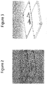
- a first step in making a laminated microfluidics with membrane valves is the making of a membrane valve assembly as illustrated in Figure 1 .
- plastic foils/films/sheets with appropriate through holes and/or slits are laminated to form a base for moulding membrane valves thereon.
- These plastic foils/films/sheets preferably have a thickness in the ranges of between 0.1mm - 0.2 mm.
- the top foil includes one through hole ( ⁇ 0,2-0,5mm) for each valve
- the second, middle foil has a slit pattern connecting each valve hole of the top foil
- the bottom foil has one hole (of about equal diameter as the through hole on the top foil) for each valve and one additional hole (of a diameter about equal the width of the slit) entering the slit pattern.
- the diameter of the through hole and the width of the slit may be adjusted, for example based on the thickness of the plastic foil.
- the middle foil may optionally be coated with adhesive to facilitate lamination of the three foils.
- the top and bottom foil may also optionally be coated with adhesive to facilitate lamination.
- the bottom foil on the side away from the middle foil is covered by a liner.
- the plastic foils/films/sheets may be connected together by any of a number of suitable bonding techniques such as, for example, gluing or by an ultrasonic or laser welding technique.
- the foils may be glue coated, thus the lamination may be accomplished by heat (80-150°C) or pressure.
- the foils may be pre-coated with adhesive for lamination by heat or pressure.
- both sides of the foils may be pre-coated. In other embodiments, only one side of the foils may be pre-coated.
- adhesive tapes such as double side adhesive tapes may be used to glue together the plastic foils.
- laser welding may be used to join plastic materials having different optical absorptions at the laser wavelength. The laser light may penetrate the transparent component (e.g., foil #1) and is then absorbed by the non-transparent component (e.g., foil #2) where it is converted into heat. The first and second plastic foils melt at the interface and welding may be effected by external pressure applied by a workholding fixture. In this manner, a welded unit inclusive of the first and second flat plastic foils may be formed. Laser welding may be used to join together up to three plastic foils at the same time (one black between two transparent).
- the laminated assembly is optionally treated for silicone rubber adhesion by, i.e., plasma treatment or chemical priming etc.
- the top foil may be covered with a breathable low tack-liner as an option to let air escape from the cavity during filling.
- the assembly may then be placed in a mould that consists of two halves to facilitate formation of an internal flexible membrane that defines part of the valve. More specifically, the assembly is placed bottom foil down on a mould half having a smooth mould surface with one or more perpendicularly protruding cylinders that are adapted to concentrically fit within the through holes associated with the three plastic foils.
- the protruding cylinders have flat top surfaces, are preferably about 0.1 mm shorter than the thickness of the laminated assembly, and have diameters that are preferably about 0.1 mm less than the diameters of the through holes.
- a second mould half also has a smooth mould surface, and is clamped on top (against the top foil liner).
- Liquid rubber for instance RTV silicone
- Figure 1b Optional liner on top foil evacuates air during filling.
- thermoplastic elastomers for purposes of the present invention include a thermoplastic polyurethane elastomer (i.e., TPU), a polyolefin-based thermoplastic elastomer (i.e., TPO), a thermoplastic elastomer based on dynamically vulcanized elastomer-thermoplastic blends (i.e., TPV), a styrene block thermoplastic elastomer, a thermoplastic polyether ester elastomer, a thermoplastic elastomer based on halogen-containing polyolefins, and a thermoplastic elastomer based on polyamides, as well as various combinations and blends thereof.
- TPU thermoplastic polyurethane elastomer
- TPO polyolefin-based thermoplastic elastomer
- TPV dynamically vulcanized elastomer-thermoplastic blends
- TPV dynamically vulcanized elastomer-
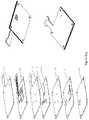
- FIG. 2 Another step in making the laminated micro fluidics with membrane valves is the making of a flow path assembly as illustrated in Figure 2 .
- a foil/sheet containing a slit pattern and another foil having through holes for liquid connections are laminated together to form the flow path.
- Soft surfaces such as flow cells and seals for connecting can be moulded on the second foil prior to laminating.
- the foils may optionally be coated, on the sides facing each other, with adhesive to facilitate lamination. While a simple slit pattern is shown here with two foil layers, a skilled person understands that many complex slit patterns may be designed, and three dimensional flow path may be formed by using more than two foil layers.
- a third step in making the laminated micro fluidics with membrane valves is the lamination together of the membrane valve assembly and the flow path assembly, after removing the breathable low tack-liner from the top of the membrane valve assembly.
- the membrane valve assembly and the individual foil sheets making up the flow path may be laminated together at the same time to form the laminated micro fluidics.
- the material used for the foil sheets are plastic foils, such as Polyester, Polycarbonate, Polyethylene terephthalate and Polyimide.
- plastic foils such as Polyester, Polycarbonate, Polyethylene terephthalate and Polyimide.
- a person skilled in the art could readily choose the correct material to use, depending on application demands on chemical resistance, flexibility etc.
- the foils are previously provided with slit and through holes suitable for forming the membrane valve assembly, the flow path assembly and the laminated microfluidics.
- the slits and through holes are made by laser cutting. Alternatively, other ways of cutting, like die cut can be used.
- Laser cutting is made with foils sitting on a low-tack liner.
- the laser beam allows for controlled fusing of the foils and films and produces clear and sealed cutting edges.
- With laser cutting even the smallest radii slit and through holes can be cut precisely and produce simple geometries at record speed.
- no pressure is exerted on the foils or films by a tool, the entire process is contact-less and consequently, the end product will turn out perfect. Laser cutting of the foil or film will not result in chipping of paint from the end product.
- the laminated microfluidics with membrane valves further includes channels for compressed air operating the valves. These channels could be made in foil sheets as shown in Figure 3 .
- the bottom foil is optionally made of a moulded plastic part with integrated connectors for air and features for positioning the unit in an analytical instrument.
- the channels could be part of the moulded plastic part, with integrated connectors for air and features for positioning the unit in an analytical instrument.
- plastic foils/parts containing channels for compressed air as well as integrated connectors for air shown in Figure 3 are laminated to the side of the membrane valve assembly.
- these plastic foils/parts are laminated to the side of the fifth plastic foil of the flow path.
- the method of making a laminated microfluidics with membrane valves further includes providing a foil containing channels for compressed air operating the valves, and a bottom foil or moulded plastic part with integrated connectors for air and features for positioning the unit in an analytical instrument.
- the foil containing channels for compressed air, and the bottom foil or moulded plastic part may be first laminated together to form a compressed air assembly. Then, it is laminated together with the membrane valve assembly and the flow path assembly to form the laminated microfluidics.
- the channels for compressed air operating the valves are part of the moulded plastic part, with integrated connectors for air and features for positioning the unit in an analytical instrument.
- the foil containing channels for compressed air and the bottom foil or moulded plastic part do not need to be first laminated together. Instead, they are laminated with the membrane valve assembly and the flow path assembly to form the laminated microfluidics. Similar to described earlier, the flow path assembly does not need to be laminated a priori. Only the membrane valve assembly needs to be laminated beforehand. All the other foil sheets may be laminated together with the membrane valve assembly at the same time to form the laminated microfluidics. Figure 4 , where the middle three layers, i.e., the membrane valve assembly is made prior to the lamination with the other parts shown, to make the laminated microfluidics.
- a laminated microfluidics with membrane valves comprising:
- the foils are made of Polyester, Polycarbonate, Polyethylene terephthalate or Polyimide.
- the flexible membrane valve is made of silicone rubber.
- the fifth foil contain through hole for liquid connections for the flow path.
- the laminated microfluidics further comprises a compressed air assembly including a sixth foil containing channels for compressed air, and a seventh, bottom foil or moulded plastic part with integrated connectors for air and features for positioning the unit in an analytical instrument, with the third foil on top of the sixth foil.
- the membrane valve assembly contains through holes for liquid connections for the flow path.
- the laminated microfluidics further comprises a compressed air assembly including a sixth foil containing channels for compressed air, and a seventh, bottom foil or moulded plastic part with integrated connectors for air and features for positioning the unit in an analytical instrument, with the fifth foil on top of the sixth foil.
- the laminated microfluidics may further comprise a moulded plastic part which comprises channels for compressed air, integrated connectors for air and features for positioning the unit in an analytical instrument.
- through holes of the laminated microfluidics may comprise soft surfaces such as flow cells and seals for connecting with other liquid handling parts of an analytical system.
- Figure 4 shows an exploded view of each individual foil/sheet that forms a laminated microfluidics with membrane valves according to certain embodiments of the invention.
- Figure 5 shows an alternative design of a laminated microfluidics with membrane valves according to certain other embodiments of the invention.
- Figure 5 (a) shows an exploded schematic of the design, as well as a top and bottom view of the laminated microfluidics with membrane valves.
- This laminated microfluidics includes a membrane valve assembly including foil sheets 3, 4 and 6, as well as foil sheets making up the flow path (foil sheets 1 and 2) and pressurized air path (foil sheets 7 and 8).
- Figure 5 (b) shows alternative exploded schematics of the design, from a top and bottom angle, respectively.
- Figure 5 (c) shows alternative exploded schematics of foil sheets 3, 4 and 6, as well as a bottom view of the finished membrane valve assembly.
- Figure 5 (d) shows exploded schematics of foil sheets 1 and 2, showing details of an exemplary flow path.
- the membrane valve assembly is formed by foil sheet 3, 4 and 6.
- Foil sheet 3 includes holes for valve membranes, soft seals/flow cells, and pressurized air.
- Foil sheet 4 includes slit patterns for silicone rubber moulding, as well as holes for pressurized air.
- this sheet is optionally double side coated for lamination adhesion and also optionally treated for rubber adhesion.
- Foil sheet 6 includes holes for valve membranes, soft seals/flow cells, pressurized air, as well as an extra hole for rubber inlet.
- side of this sheet that facing up is optionally treated for rubber adhesion.
- the foil sheet 1 is the cover foil, including holes for liquid transport (liquid connections) and holes for pressurized air connections.
- Foil sheet 2 contains liquid channels and holes for pressurized air.
- this foil is optionally double side coated for lamination adhesion. These foils, when laminated together with the membrane valve assembly, form microfluidic channels for liquid handling.
- Foil sheet 7 and 8 form the channels for compressed air.
- Foil sheet 7 includes channels for pressurized air cut outs and hole for flow cell moulding. During manufacturing of the membrane valve assembly, this sheet may be double side coated for lamination adhesion.
- Foil sheet 8 is the cover foil with hole for flow cell moulding.
- the holes for pressurized air may alternatively located on foil sheet 8, instead of on foil sheets 1-6.
- the flow cell with via holes may connect the microfluidic channels with other functionalities of a bioanalytical system, such as a sensorchip, to deliver liquid to the sensorchip.
- the liquid connections are shown to be on an elongated part of the top foil sheet 1, away from the center of the laminated microfluidics.
- such placement of the liquid connections enables direct connection between these liquid connections and other parts of a bioanalytical system, and reduced/eliminates the use of tubing.
- the foil sheet used may be more flexible, or stiffer, and the liquid connections may be closer or further away from the center of the laminated microfluidics.
- the foil sheets may be bendable, thus the microfluidics is bendable.
Landscapes
- Chemical & Material Sciences (AREA)
- Health & Medical Sciences (AREA)
- Dispersion Chemistry (AREA)
- Engineering & Computer Science (AREA)
- Clinical Laboratory Science (AREA)
- Hematology (AREA)
- General Health & Medical Sciences (AREA)
- Chemical Kinetics & Catalysis (AREA)
- Analytical Chemistry (AREA)
- Mechanical Engineering (AREA)
- General Engineering & Computer Science (AREA)
- Manufacturing & Machinery (AREA)
- Automatic Analysis And Handling Materials Therefor (AREA)
- Reciprocating Pumps (AREA)
Claims (15)
- Verfahren zum Herstellen einer laminierten Mikrofluidikvorrichtung, die Membranventiles enthält, wobei das Verfahren umfasst:a) Erzeugen einer Membranventilanordnung, umfassend:(1) Laminieren von drei Kunststofffolien untereinander, wobei die erste, obere Folie ein Ventildurchgangsloch für jedes Ventil umfasst, die zweite, mittlere Folie ein Schlitzmuster aufweist, das jedes Ventilloch der oberen Folie verbindet, und die dritte, untere Folie ein Ventildurchgangsloch für jedes Ventil und ein zusätzliches Loch, das in das Schlitzmuster eindringt, aufweist, und dadurch eine laminierte Folie erzeugt;(2) Positionieren der laminierten Folie auf einer Formhälfte, die eine glatte Formhälftenoberfläche aufweist, mit der unteren Folie zu der Oberfläche zeigend, wobei die Oberfläche einen oder mehrere rechtwinkelig vorstehende Zylinder enthält, die konzentrisch in die Ventildurchgangslöcher der laminierten Folie einpassen, aber noch Raum lassen, um eine Ventilmembrane zu formen, und Klemmen einer zweiten Formhälfte, um die Form zu schließen;(3) Formen der Ventilmembrane durch Einspritzen eines flüssigen Kautschuks durch einen Trichter, der der unteren Formhälfte und dem zusätzlichen Loch an der unteren Folienlage zugeordnet ist, und dessen Aushärtenlassens; undb) Laminieren der Membranventilanordnung und eines Fließpfads, wobei der Fließpfad eine vierte und eine fünfte Kunststofffolie umfasst, wobei die vierte Folie ein weiteres Schlitzmuster beinhaltet, mit der vierten Folie über der ersten Folie und der fünften Folie über der vierten Folie.
- Verfahren nach Anspruch 1, wobei die fünfte Folie ein Durchgangsloch für Flüssigkeitsverbindungen für den Fließpfad beinhaltet.
- Verfahren nach Anspruch 1, wobei die Membranventilanordnung weitere Durchgangslöcher für Flüssigkeitsverbindungen für den Fließpfad beinhaltet.
- Verfahren nach Anspruch 2, weiter umfassend:
weiteres Laminieren einer Druckluftanordnung, die eine sechste Folie, die Kanäle für Druckluft beinhaltet, und eine siebte, untere Folie oder ein geformtes Kunststoffteil mit integrierten Anschlüssen für Druckluft und Merkmalen zum Positionieren der Einheit in ein Analyseinstrument, mit der dritten Folie über der sechsten Folie, enthält. - Verfahren nach Anspruch 4, wobei die Druckluftanordnung vor Schritt a) zuerst untereinander laminiert wird.
- Verfahren nach Anspruch 4, wobei die sechste Folie und die siebte, untere Folie oder das geformte Kunststoffteil mit der Membranventilanordnung und dem Fließpfad gleichzeitig laminiert werden.
- Verfahren nach Anspruch 1 oder 2 oder 3, umfassend den weiteren Schritt: c) Laminieren eines geformten Kunststoffteils, das Kanäle für Druckluft, integrierte Anschlüsse für Luft und Merkmale zum Positionieren der Einheit in ein Analyseinstrument umfasst.
- Verfahren nach Anspruch 1, wobei die zwei oder mehreren Kunststofffolien, die den Fließpfad formen, gleichzeitig mit der Membranventilanordnung untereinander laminiert werden.
- Verfahren nach Anspruch 3, weiter umfassend:
weiteres Laminieren einer Druckluftanordnung, die eine sechste Folie, die Kanäle für Druckluft beinhaltet, und eine siebte, untere Folie oder ein geformtes Kunststoffteils mit integrierten Anschlüssen für Luft und Merkmalen zum Positionieren der Einheit in Analyseinstrument, mit der fünften Folie über der sechsten Folie, enthält. - Verfahren nach Anspruch 9, wobei die sechste Folie und die siebte, untere Folie oder das geformte Kunststoffteil mit der Membranventilanordnung und dem Fließpfad gleichzeitig laminiert werden.
- Laminierte Mikrofluidikvorrichtung, die Membranventile aufweist, umfassend:eine Membranventilanordnung, umfassend:(1) drei untereinander laminierte Kunststofffolien (3,4,6), eine erste, obere Folie (3), die ein Ventildurchgangsloch für jedes Ventil umfasst, eine zweite, mittlere Folie (4), die ein Schlitzmuster aufweist, das jedes Ventilloch der oberen Folie verbindet, und eine dritte, untere Folie (6), die ein Ventildurchgangsloch für jedes Ventil und ein zusätzliches Loch, das in das Schlitzmuster eindringt, aufweist;(2) eine flexible Membrane, die in den Durchgangslöchern der ersten und dritten Folie durch einen flüssigen Kautschuk geformt ist, der durch das zusätzliche Loch in der unteren Folienlage und durch das Schlitzmuster eingespritzt wird; und umfassend einen Fließpfad, umfassend eine vierte (2) und eine fünfte (1) Kunststofffolie, wobei die vierte Folie ein weiteres Schlitzmuster beinhaltet, mit der vierten Folie über der ersten Folie und der fünften Folie über der vierten Folie;wobei die Membranventilanordnung und der Fließpfad untereinander laminiert werden.
- Laminierte Mikrofluidikvorrichtung nach Anspruch 11, wobei die fünfte Folie Durchgangsloch für Flüssigkeitsverbindungen für den Fließpfad beinhaltet.
- Laminierte Mikrofluidikvorrichtung nach Anspruch 11, wobei die Membranventilanordnung Durchgangslöcher für Flüssigkeitsverbindungen für den Fließpfad beinhaltet.
- Laminierte Mikrofluidikvorrichtung nach Anspruch 12, weiter umfassend:
eine Druckluftanordnung, die eine sechste Folie, die Kanäle für Druckluft beinhaltet, und eine siebte, untere Folie oder ein geformte Kunststoffteil mit integrierten Anschlüssen für Luft und Merkmalen zum Positionieren der Einheit in ein Analyseinstrument, mit der dritten Folie über der sechsten Folie, enthält. - Laminierte Mikrofluidikvorrichtung nach einem der Ansprüche 11 - 13, weiter umfassend:
3) ein geformtes Kunststoffteil, das Kanäle für Druckluft, integrierte Anschlüsse für Luft und Merkmale zum Positionieren der Einheit in an Analyseinstrument umfasst.
Applications Claiming Priority (2)
| Application Number | Priority Date | Filing Date | Title |
|---|---|---|---|
| US201361918357P | 2013-12-19 | 2013-12-19 | |
| PCT/EP2014/075989 WO2015090908A1 (en) | 2013-12-19 | 2014-11-28 | Laminated microfluidic device with membrane valves |
Publications (2)
| Publication Number | Publication Date |
|---|---|
| EP3083052A1 EP3083052A1 (de) | 2016-10-26 |
| EP3083052B1 true EP3083052B1 (de) | 2019-09-25 |
Family
ID=51987167
Family Applications (1)
| Application Number | Title | Priority Date | Filing Date |
|---|---|---|---|
| EP14803172.7A Active EP3083052B1 (de) | 2013-12-19 | 2014-11-28 | Laminierte mikrofluidische vorrichtung mit membranventilen |
Country Status (4)
| Country | Link |
|---|---|
| US (1) | US9975123B2 (de) |
| EP (1) | EP3083052B1 (de) |
| CN (1) | CN105813753B (de) |
| WO (1) | WO2015090908A1 (de) |
Families Citing this family (1)
| Publication number | Priority date | Publication date | Assignee | Title |
|---|---|---|---|---|
| CN112096894B (zh) * | 2019-06-18 | 2025-01-07 | 南京纳摩尔仪器有限公司 | 一种多通道电磁选择阀 |
Family Cites Families (12)
| Publication number | Priority date | Publication date | Assignee | Title |
|---|---|---|---|---|
| SE462408B (sv) | 1988-11-10 | 1990-06-18 | Pharmacia Ab | Optiskt biosensorsystem utnyttjande ytplasmonresonans foer detektering av en specific biomolekyl, saett att kalibrera sensoranordningen samt saett att korrigera foer baslinjedrift i systemet |
| SE9200917D0 (sv) | 1991-08-20 | 1992-03-25 | Pharmacia Biosensor Ab | Assay method |
| SE9201984D0 (sv) | 1992-06-29 | 1992-06-29 | Pharmacia Biosensor Ab | Improvement in optical assays |
| US5932799A (en) | 1997-07-21 | 1999-08-03 | Ysi Incorporated | Microfluidic analyzer module |
| EP1125129A1 (de) * | 1998-10-13 | 2001-08-22 | Biomicro Systems, Inc. | Komponenten eines flüssigkeitskreislaufes, basierend auf passiven flüssigkeitsdynamiken |
| JP4275408B2 (ja) | 2000-11-02 | 2009-06-10 | ジーイー・ヘルスケア・バイオサイエンス・アクチボラグ | 微小液体輸送アセンブリの一体型付属弁 |
| US6767194B2 (en) | 2001-01-08 | 2004-07-27 | President And Fellows Of Harvard College | Valves and pumps for microfluidic systems and method for making microfluidic systems |
| WO2003015923A1 (en) * | 2001-08-20 | 2003-02-27 | Biomicro Systems, Inc. | Fluid mixing in low aspect ratio chambers |
| US6919046B2 (en) | 2001-06-07 | 2005-07-19 | Nanostream, Inc. | Microfluidic analytical devices and methods |
| US7837821B2 (en) | 2004-10-13 | 2010-11-23 | Rheonix, Inc. | Laminated microfluidic structures and method for making |
| JP5377972B2 (ja) * | 2005-11-22 | 2013-12-25 | マイクロラボ ピーティーワイ エルティーディー | 流体構造、装置、方法、及び機器構成方法 |
| US7905133B2 (en) | 2007-12-28 | 2011-03-15 | Thar Instruments, Inc. | Variable ratio flow splitter for a flowstream |
-
2014
- 2014-11-28 WO PCT/EP2014/075989 patent/WO2015090908A1/en not_active Ceased
- 2014-11-28 EP EP14803172.7A patent/EP3083052B1/de active Active
- 2014-11-28 CN CN201480069363.9A patent/CN105813753B/zh active Active
- 2014-11-28 US US15/103,501 patent/US9975123B2/en active Active
Non-Patent Citations (1)
| Title |
|---|
| None * |
Also Published As
| Publication number | Publication date |
|---|---|
| EP3083052A1 (de) | 2016-10-26 |
| CN105813753B (zh) | 2018-03-30 |
| WO2015090908A1 (en) | 2015-06-25 |
| CN105813753A (zh) | 2016-07-27 |
| US9975123B2 (en) | 2018-05-22 |
| US20160310946A1 (en) | 2016-10-27 |
Similar Documents
| Publication | Publication Date | Title |
|---|---|---|
| US6988317B2 (en) | Valve integrally associated with microfluidic liquid transport assembly | |
| EP1015878B1 (de) | Verfahren zur herstellung von strukturen von umschlossenen mikrokanälen | |
| AU2002212904A1 (en) | Valve integrally associated with microfluidic liquid transport assembly | |
| US8226907B2 (en) | Microfluidic devices and methods of making the same | |
| US20130287645A1 (en) | Microfluidic chamber device and fabrication | |
| US20020187074A1 (en) | Microfluidic analytical devices and methods | |
| Wan et al. | Solvent bonding for fabrication of PMMA and COP microfluidic devices | |
| CN102721820B (zh) | 一种制备具有集成化气动微阀的组装式高聚物微流控芯片的方法 | |
| GB2445738A (en) | Microfluidic device | |
| CN107159329A (zh) | 一种用于样品检测的芯片及其封装方法 | |
| US20100060998A1 (en) | Microchip | |
| WO2010038897A1 (ja) | 分析用具およびその製造方法 | |
| JP2002515351A (ja) | ミクロ構造化されたフィルム | |
| EP3083052B1 (de) | Laminierte mikrofluidische vorrichtung mit membranventilen | |
| US20250196130A1 (en) | Fluid Device and Method for Manufacturing Fluid Devices | |
| Simone et al. | A microvalve for hybrid microfluidic systems | |
| KR101151221B1 (ko) | 마이크로 채널을 가진 구조물의 제조 방법 및 그 구조물 | |
| KR102431519B1 (ko) | 나노구조물을 포함하는 농도구배 세포칩, 이의 제조 방법 및 이를 이용한 영상 분석 장치 | |
| Schuenemann et al. | Packaging of disposable chips for bioanalytical applications [microfluidics] | |
| JP2005043075A (ja) | 流量制御装置及び流量制御システム | |
| CN108855264A (zh) | 一种多用途多指标微流控芯片 | |
| JP6017793B2 (ja) | マイクロチップ | |
| JP2005088111A (ja) | 分離・抽出機構を有するマイクロリアクターの製造方法 | |
| JP5390366B2 (ja) | 試料操作素子 | |
| Hosseinkhannazer | Polymeric optofluidic biochips |
Legal Events
| Date | Code | Title | Description |
|---|---|---|---|
| PUAI | Public reference made under article 153(3) epc to a published international application that has entered the european phase |
Free format text: ORIGINAL CODE: 0009012 |
|
| 17P | Request for examination filed |
Effective date: 20160601 |
|
| AK | Designated contracting states |
Kind code of ref document: A1 Designated state(s): AL AT BE BG CH CY CZ DE DK EE ES FI FR GB GR HR HU IE IS IT LI LT LU LV MC MK MT NL NO PL PT RO RS SE SI SK SM TR |
|
| AX | Request for extension of the european patent |
Extension state: BA ME |
|
| DAX | Request for extension of the european patent (deleted) | ||
| STAA | Information on the status of an ep patent application or granted ep patent |
Free format text: STATUS: EXAMINATION IS IN PROGRESS |
|
| 17Q | First examination report despatched |
Effective date: 20180322 |
|
| REG | Reference to a national code |
Ref country code: DE Ref legal event code: R079 Ref document number: 602014054289 Country of ref document: DE Free format text: PREVIOUS MAIN CLASS: B01L0003000000 Ipc: B29K0021000000 |
|
| RIC1 | Information provided on ipc code assigned before grant |
Ipc: B29C 45/14 20060101ALI20190321BHEP Ipc: F16K 99/00 20060101ALI20190321BHEP Ipc: B01L 3/00 20060101ALI20190321BHEP Ipc: B32B 38/00 20060101ALI20190321BHEP Ipc: B29K 21/00 20060101AFI20190321BHEP |
|
| GRAP | Despatch of communication of intention to grant a patent |
Free format text: ORIGINAL CODE: EPIDOSNIGR1 |
|
| STAA | Information on the status of an ep patent application or granted ep patent |
Free format text: STATUS: GRANT OF PATENT IS INTENDED |
|
| INTG | Intention to grant announced |
Effective date: 20190430 |
|
| GRAS | Grant fee paid |
Free format text: ORIGINAL CODE: EPIDOSNIGR3 |
|
| GRAA | (expected) grant |
Free format text: ORIGINAL CODE: 0009210 |
|
| STAA | Information on the status of an ep patent application or granted ep patent |
Free format text: STATUS: THE PATENT HAS BEEN GRANTED |
|
| AK | Designated contracting states |
Kind code of ref document: B1 Designated state(s): AL AT BE BG CH CY CZ DE DK EE ES FI FR GB GR HR HU IE IS IT LI LT LU LV MC MK MT NL NO PL PT RO RS SE SI SK SM TR |
|
| REG | Reference to a national code |
Ref country code: GB Ref legal event code: FG4D |
|
| REG | Reference to a national code |
Ref country code: CH Ref legal event code: EP |
|
| REG | Reference to a national code |
Ref country code: DE Ref legal event code: R096 Ref document number: 602014054289 Country of ref document: DE |
|
| REG | Reference to a national code |
Ref country code: AT Ref legal event code: REF Ref document number: 1183413 Country of ref document: AT Kind code of ref document: T Effective date: 20191015 |
|
| REG | Reference to a national code |
Ref country code: IE Ref legal event code: FG4D |
|
| REG | Reference to a national code |
Ref country code: NL Ref legal event code: MP Effective date: 20190925 |
|
| PG25 | Lapsed in a contracting state [announced via postgrant information from national office to epo] |
Ref country code: BG Free format text: LAPSE BECAUSE OF FAILURE TO SUBMIT A TRANSLATION OF THE DESCRIPTION OR TO PAY THE FEE WITHIN THE PRESCRIBED TIME-LIMIT Effective date: 20191225 Ref country code: SE Free format text: LAPSE BECAUSE OF FAILURE TO SUBMIT A TRANSLATION OF THE DESCRIPTION OR TO PAY THE FEE WITHIN THE PRESCRIBED TIME-LIMIT Effective date: 20190925 Ref country code: NO Free format text: LAPSE BECAUSE OF FAILURE TO SUBMIT A TRANSLATION OF THE DESCRIPTION OR TO PAY THE FEE WITHIN THE PRESCRIBED TIME-LIMIT Effective date: 20191225 Ref country code: HR Free format text: LAPSE BECAUSE OF FAILURE TO SUBMIT A TRANSLATION OF THE DESCRIPTION OR TO PAY THE FEE WITHIN THE PRESCRIBED TIME-LIMIT Effective date: 20190925 Ref country code: FI Free format text: LAPSE BECAUSE OF FAILURE TO SUBMIT A TRANSLATION OF THE DESCRIPTION OR TO PAY THE FEE WITHIN THE PRESCRIBED TIME-LIMIT Effective date: 20190925 Ref country code: LT Free format text: LAPSE BECAUSE OF FAILURE TO SUBMIT A TRANSLATION OF THE DESCRIPTION OR TO PAY THE FEE WITHIN THE PRESCRIBED TIME-LIMIT Effective date: 20190925 |
|
| REG | Reference to a national code |
Ref country code: LT Ref legal event code: MG4D |
|
| PG25 | Lapsed in a contracting state [announced via postgrant information from national office to epo] |
Ref country code: GR Free format text: LAPSE BECAUSE OF FAILURE TO SUBMIT A TRANSLATION OF THE DESCRIPTION OR TO PAY THE FEE WITHIN THE PRESCRIBED TIME-LIMIT Effective date: 20191226 Ref country code: LV Free format text: LAPSE BECAUSE OF FAILURE TO SUBMIT A TRANSLATION OF THE DESCRIPTION OR TO PAY THE FEE WITHIN THE PRESCRIBED TIME-LIMIT Effective date: 20190925 Ref country code: RS Free format text: LAPSE BECAUSE OF FAILURE TO SUBMIT A TRANSLATION OF THE DESCRIPTION OR TO PAY THE FEE WITHIN THE PRESCRIBED TIME-LIMIT Effective date: 20190925 |
|
| REG | Reference to a national code |
Ref country code: AT Ref legal event code: MK05 Ref document number: 1183413 Country of ref document: AT Kind code of ref document: T Effective date: 20190925 |
|
| PG25 | Lapsed in a contracting state [announced via postgrant information from national office to epo] |
Ref country code: ES Free format text: LAPSE BECAUSE OF FAILURE TO SUBMIT A TRANSLATION OF THE DESCRIPTION OR TO PAY THE FEE WITHIN THE PRESCRIBED TIME-LIMIT Effective date: 20190925 Ref country code: AL Free format text: LAPSE BECAUSE OF FAILURE TO SUBMIT A TRANSLATION OF THE DESCRIPTION OR TO PAY THE FEE WITHIN THE PRESCRIBED TIME-LIMIT Effective date: 20190925 Ref country code: NL Free format text: LAPSE BECAUSE OF FAILURE TO SUBMIT A TRANSLATION OF THE DESCRIPTION OR TO PAY THE FEE WITHIN THE PRESCRIBED TIME-LIMIT Effective date: 20190925 Ref country code: PT Free format text: LAPSE BECAUSE OF FAILURE TO SUBMIT A TRANSLATION OF THE DESCRIPTION OR TO PAY THE FEE WITHIN THE PRESCRIBED TIME-LIMIT Effective date: 20200127 Ref country code: PL Free format text: LAPSE BECAUSE OF FAILURE TO SUBMIT A TRANSLATION OF THE DESCRIPTION OR TO PAY THE FEE WITHIN THE PRESCRIBED TIME-LIMIT Effective date: 20190925 Ref country code: RO Free format text: LAPSE BECAUSE OF FAILURE TO SUBMIT A TRANSLATION OF THE DESCRIPTION OR TO PAY THE FEE WITHIN THE PRESCRIBED TIME-LIMIT Effective date: 20190925 Ref country code: AT Free format text: LAPSE BECAUSE OF FAILURE TO SUBMIT A TRANSLATION OF THE DESCRIPTION OR TO PAY THE FEE WITHIN THE PRESCRIBED TIME-LIMIT Effective date: 20190925 Ref country code: EE Free format text: LAPSE BECAUSE OF FAILURE TO SUBMIT A TRANSLATION OF THE DESCRIPTION OR TO PAY THE FEE WITHIN THE PRESCRIBED TIME-LIMIT Effective date: 20190925 Ref country code: IT Free format text: LAPSE BECAUSE OF FAILURE TO SUBMIT A TRANSLATION OF THE DESCRIPTION OR TO PAY THE FEE WITHIN THE PRESCRIBED TIME-LIMIT Effective date: 20190925 |
|
| PG25 | Lapsed in a contracting state [announced via postgrant information from national office to epo] |
Ref country code: SM Free format text: LAPSE BECAUSE OF FAILURE TO SUBMIT A TRANSLATION OF THE DESCRIPTION OR TO PAY THE FEE WITHIN THE PRESCRIBED TIME-LIMIT Effective date: 20190925 Ref country code: SK Free format text: LAPSE BECAUSE OF FAILURE TO SUBMIT A TRANSLATION OF THE DESCRIPTION OR TO PAY THE FEE WITHIN THE PRESCRIBED TIME-LIMIT Effective date: 20190925 Ref country code: CZ Free format text: LAPSE BECAUSE OF FAILURE TO SUBMIT A TRANSLATION OF THE DESCRIPTION OR TO PAY THE FEE WITHIN THE PRESCRIBED TIME-LIMIT Effective date: 20190925 Ref country code: IS Free format text: LAPSE BECAUSE OF FAILURE TO SUBMIT A TRANSLATION OF THE DESCRIPTION OR TO PAY THE FEE WITHIN THE PRESCRIBED TIME-LIMIT Effective date: 20200224 |
|
| REG | Reference to a national code |
Ref country code: DE Ref legal event code: R097 Ref document number: 602014054289 Country of ref document: DE |
|
| REG | Reference to a national code |
Ref country code: CH Ref legal event code: PL |
|
| PG2D | Information on lapse in contracting state deleted |
Ref country code: IS |
|
| PG25 | Lapsed in a contracting state [announced via postgrant information from national office to epo] |
Ref country code: LU Free format text: LAPSE BECAUSE OF NON-PAYMENT OF DUE FEES Effective date: 20191128 Ref country code: DK Free format text: LAPSE BECAUSE OF FAILURE TO SUBMIT A TRANSLATION OF THE DESCRIPTION OR TO PAY THE FEE WITHIN THE PRESCRIBED TIME-LIMIT Effective date: 20190925 Ref country code: MC Free format text: LAPSE BECAUSE OF FAILURE TO SUBMIT A TRANSLATION OF THE DESCRIPTION OR TO PAY THE FEE WITHIN THE PRESCRIBED TIME-LIMIT Effective date: 20190925 Ref country code: LI Free format text: LAPSE BECAUSE OF NON-PAYMENT OF DUE FEES Effective date: 20191130 Ref country code: CH Free format text: LAPSE BECAUSE OF NON-PAYMENT OF DUE FEES Effective date: 20191130 Ref country code: IS Free format text: LAPSE BECAUSE OF FAILURE TO SUBMIT A TRANSLATION OF THE DESCRIPTION OR TO PAY THE FEE WITHIN THE PRESCRIBED TIME-LIMIT Effective date: 20200126 |
|
| PLBE | No opposition filed within time limit |
Free format text: ORIGINAL CODE: 0009261 |
|
| STAA | Information on the status of an ep patent application or granted ep patent |
Free format text: STATUS: NO OPPOSITION FILED WITHIN TIME LIMIT |
|
| RAP2 | Party data changed (patent owner data changed or rights of a patent transferred) |
Owner name: CYTIVA SWEDEN AB |
|
| REG | Reference to a national code |
Ref country code: BE Ref legal event code: MM Effective date: 20191130 |
|
| 26N | No opposition filed |
Effective date: 20200626 |
|
| PG25 | Lapsed in a contracting state [announced via postgrant information from national office to epo] |
Ref country code: IE Free format text: LAPSE BECAUSE OF NON-PAYMENT OF DUE FEES Effective date: 20191128 |
|
| PG25 | Lapsed in a contracting state [announced via postgrant information from national office to epo] |
Ref country code: SI Free format text: LAPSE BECAUSE OF FAILURE TO SUBMIT A TRANSLATION OF THE DESCRIPTION OR TO PAY THE FEE WITHIN THE PRESCRIBED TIME-LIMIT Effective date: 20190925 Ref country code: BE Free format text: LAPSE BECAUSE OF NON-PAYMENT OF DUE FEES Effective date: 20191130 |
|
| REG | Reference to a national code |
Ref country code: DE Ref legal event code: R081 Ref document number: 602014054289 Country of ref document: DE Owner name: CYTIVA SWEDEN AB, SE Free format text: FORMER OWNER: GE HEALTHCARE BIO-SCIENCES AB, UPPSALA, SE |
|
| PG25 | Lapsed in a contracting state [announced via postgrant information from national office to epo] |
Ref country code: CY Free format text: LAPSE BECAUSE OF FAILURE TO SUBMIT A TRANSLATION OF THE DESCRIPTION OR TO PAY THE FEE WITHIN THE PRESCRIBED TIME-LIMIT Effective date: 20190925 |
|
| PG25 | Lapsed in a contracting state [announced via postgrant information from national office to epo] |
Ref country code: HU Free format text: LAPSE BECAUSE OF FAILURE TO SUBMIT A TRANSLATION OF THE DESCRIPTION OR TO PAY THE FEE WITHIN THE PRESCRIBED TIME-LIMIT; INVALID AB INITIO Effective date: 20141128 Ref country code: MT Free format text: LAPSE BECAUSE OF FAILURE TO SUBMIT A TRANSLATION OF THE DESCRIPTION OR TO PAY THE FEE WITHIN THE PRESCRIBED TIME-LIMIT Effective date: 20190925 |
|
| PG25 | Lapsed in a contracting state [announced via postgrant information from national office to epo] |
Ref country code: TR Free format text: LAPSE BECAUSE OF FAILURE TO SUBMIT A TRANSLATION OF THE DESCRIPTION OR TO PAY THE FEE WITHIN THE PRESCRIBED TIME-LIMIT Effective date: 20190925 |
|
| PG25 | Lapsed in a contracting state [announced via postgrant information from national office to epo] |
Ref country code: MK Free format text: LAPSE BECAUSE OF FAILURE TO SUBMIT A TRANSLATION OF THE DESCRIPTION OR TO PAY THE FEE WITHIN THE PRESCRIBED TIME-LIMIT Effective date: 20190925 |
|
| P01 | Opt-out of the competence of the unified patent court (upc) registered |
Effective date: 20230526 |
|
| PGFP | Annual fee paid to national office [announced via postgrant information from national office to epo] |
Ref country code: DE Payment date: 20251126 Year of fee payment: 12 |
|
| PGFP | Annual fee paid to national office [announced via postgrant information from national office to epo] |
Ref country code: GB Payment date: 20251125 Year of fee payment: 12 |
|
| PGFP | Annual fee paid to national office [announced via postgrant information from national office to epo] |
Ref country code: FR Payment date: 20251125 Year of fee payment: 12 |