EP3083449B1 - Kapsel und system zur herstellung von getränken - Google Patents
Kapsel und system zur herstellung von getränken Download PDFInfo
- Publication number
- EP3083449B1 EP3083449B1 EP13811915.1A EP13811915A EP3083449B1 EP 3083449 B1 EP3083449 B1 EP 3083449B1 EP 13811915 A EP13811915 A EP 13811915A EP 3083449 B1 EP3083449 B1 EP 3083449B1
- Authority
- EP
- European Patent Office
- Prior art keywords
- capsule
- wall
- receptacle
- axis
- central axis
- Prior art date
- Legal status (The legal status is an assumption and is not a legal conclusion. Google has not performed a legal analysis and makes no representation as to the accuracy of the status listed.)
- Active
Links
Images


Classifications
-
- B—PERFORMING OPERATIONS; TRANSPORTING
- B65—CONVEYING; PACKING; STORING; HANDLING THIN OR FILAMENTARY MATERIAL
- B65D—CONTAINERS FOR STORAGE OR TRANSPORT OF ARTICLES OR MATERIALS, e.g. BAGS, BARRELS, BOTTLES, BOXES, CANS, CARTONS, CRATES, DRUMS, JARS, TANKS, HOPPERS, FORWARDING CONTAINERS; ACCESSORIES, CLOSURES, OR FITTINGS THEREFOR; PACKAGING ELEMENTS; PACKAGES
- B65D85/00—Containers, packaging elements or packages, specially adapted for particular articles or materials
- B65D85/70—Containers, packaging elements or packages, specially adapted for particular articles or materials for materials not otherwise provided for
- B65D85/804—Disposable containers or packages with contents which are mixed, infused or dissolved in situ, i.e. without having been previously removed from the package
- B65D85/8043—Packages adapted to allow liquid to pass through the contents
- B65D85/8055—Means for influencing the liquid flow inside the package
-
- B—PERFORMING OPERATIONS; TRANSPORTING
- B65—CONVEYING; PACKING; STORING; HANDLING THIN OR FILAMENTARY MATERIAL
- B65D—CONTAINERS FOR STORAGE OR TRANSPORT OF ARTICLES OR MATERIALS, e.g. BAGS, BARRELS, BOTTLES, BOXES, CANS, CARTONS, CRATES, DRUMS, JARS, TANKS, HOPPERS, FORWARDING CONTAINERS; ACCESSORIES, CLOSURES, OR FITTINGS THEREFOR; PACKAGING ELEMENTS; PACKAGES
- B65D85/00—Containers, packaging elements or packages, specially adapted for particular articles or materials
- B65D85/70—Containers, packaging elements or packages, specially adapted for particular articles or materials for materials not otherwise provided for
- B65D85/804—Disposable containers or packages with contents which are mixed, infused or dissolved in situ, i.e. without having been previously removed from the package
- B65D85/8043—Packages adapted to allow liquid to pass through the contents
- B65D85/8049—Details of the inlet
-
- A—HUMAN NECESSITIES
- A47—FURNITURE; DOMESTIC ARTICLES OR APPLIANCES; COFFEE MILLS; SPICE MILLS; SUCTION CLEANERS IN GENERAL
- A47J—KITCHEN EQUIPMENT; COFFEE MILLS; SPICE MILLS; APPARATUS FOR MAKING BEVERAGES
- A47J31/00—Apparatus for making beverages
- A47J31/40—Beverage-making apparatus with dispensing means for adding a measured quantity of ingredients, e.g. coffee, water, sugar, cocoa, milk, tea
- A47J31/407—Beverage-making apparatus with dispensing means for adding a measured quantity of ingredients, e.g. coffee, water, sugar, cocoa, milk, tea with ingredient-containing cartridges; Cartridge-perforating means
-
- A—HUMAN NECESSITIES
- A23—FOODS OR FOODSTUFFS; TREATMENT THEREOF, NOT COVERED BY OTHER CLASSES
- A23F—COFFEE; TEA; THEIR SUBSTITUTES; MANUFACTURE, PREPARATION, OR INFUSION THEREOF
- A23F5/00—Coffee; Coffee substitutes; Preparations thereof
- A23F5/24—Extraction of coffee; Coffee extracts; Making instant coffee
- A23F5/26—Extraction of water soluble constituents
- A23F5/262—Extraction of water soluble constituents the extraction liquid flowing through a stationary bed of solid substances, e.g. in percolation columns
-
- A—HUMAN NECESSITIES
- A47—FURNITURE; DOMESTIC ARTICLES OR APPLIANCES; COFFEE MILLS; SPICE MILLS; SUCTION CLEANERS IN GENERAL
- A47J—KITCHEN EQUIPMENT; COFFEE MILLS; SPICE MILLS; APPARATUS FOR MAKING BEVERAGES
- A47J31/00—Apparatus for making beverages
- A47J31/44—Parts or details or accessories of beverage-making apparatus
- A47J31/4403—Constructional details
-
- B—PERFORMING OPERATIONS; TRANSPORTING
- B65—CONVEYING; PACKING; STORING; HANDLING THIN OR FILAMENTARY MATERIAL
- B65D—CONTAINERS FOR STORAGE OR TRANSPORT OF ARTICLES OR MATERIALS, e.g. BAGS, BARRELS, BOTTLES, BOXES, CANS, CARTONS, CRATES, DRUMS, JARS, TANKS, HOPPERS, FORWARDING CONTAINERS; ACCESSORIES, CLOSURES, OR FITTINGS THEREFOR; PACKAGING ELEMENTS; PACKAGES
- B65D85/00—Containers, packaging elements or packages, specially adapted for particular articles or materials
- B65D85/70—Containers, packaging elements or packages, specially adapted for particular articles or materials for materials not otherwise provided for
- B65D85/804—Disposable containers or packages with contents which are mixed, infused or dissolved in situ, i.e. without having been previously removed from the package
- B65D85/8043—Packages adapted to allow liquid to pass through the contents
- B65D85/8052—Details of the outlet
Definitions
- the present invention relates to a capsule for preparing beverage, such as coffee, from a dose of one or more products contained inside the capsule by a brewing liquid injected into the capsule to extract the product contained therein.
- the invention also relates to a system for beverage preparation comprising a capsule according to the invention and a brewing device (beverage preparation device) for injecting the brewing liquid into the capsule.
- Beverage capsules comprise a hollow container portion that houses a dose of at least one extractable or reconstitutable product, generally ground coffee, but also tea herbal extracts, instant i.e. powdered drinks and liquid concentrates, are known in the art.
- the capsules also comprise a portion that interacts with a brewing device to prepare the required beverage.
- the typical brewing device comprises water heating means, an enclosing member, or receptacle, intended to cooperate with the capsule to define a preparation chamber and a pump or similar means so that the brewing liquid, usually but not exclusively hot water under pressure, can be supplied to the capsule for the extraction or reconstitution of the beverage from the dose of product contained therein.
- the enclosing member, or receptacle is usually movable with respect to the capsule, or vice versa, between an open position in which the capsule can be inserted into the brewing device and a closed position wherein the capsule is at least in part housed inside the receptacle.
- the receptacle is further provided with a circular pressing edge, intended to cooperate with the capsule, and in particular with a flange-like rim extending from the capsule, in order to form a seal tight engagement.
- the capsule needs to be dimensioned so that it can be inserted into the brewing device, and to avoid undesired contacts between the capsule and in particular the inlet wall of the capsule with the receptacle, and in particular with its circular pressing edge. Additionally, the capsule needs to be dimensioned so that it can be housed in the receptacle when the latter is moved towards the closed position.
- the dimension of the capsule, and in particular the internal volume of its hollow body must be able to contain a certain amount of extractable product, for example coffee powder, in order to obtain the desired quality and quantity of the brewed beverage.
- extractable product for example coffee powder
- the capsule is inserted into the brewing device with its central axis inclined with respect to the axis along which the receptacle is movable between the open and closed position.
- a capsule is fed into the receptacle of the brewing device and is fed with the brewing liquid, such as hot water.
- the injected brewing liquid passes through the capsule and thus creates by dissolving the soluble solids contained in the foodstuff or solubilising the powder contained in the capsule or otherwise diluting the liquid concentrate contained therein.
- the injection of the brewing liquid inside the capsule allows for the constitution of the beverage from the ingredient enclosed therein.
- the beverage thus formed exits the capsule to reach a beverage collector or outlet spout and thence a cup or a container.
- Both “open” and “closed” capsules need to be dimensioned in order to maximize the internal volume and also allowing their easily and effective insertion inside the receptacle of the brewing devices.
- the brewing device is provided with piercing means, usually in the form of one or more protruding blades or perforators, intended to contact and to perforate the inlet wall and/or the outlet wall of the capsule. Apertures, or holes, formed by the piercing means allow the passage of the brewing liquid inside the capsule form the inlet wall and/or the extraction of the prepared beverage form the outlet wall.
- Feeding of brewing hot water by piercing the inlet wall of the capsule is a method well known in the art and is disclosed in several prior art documents.
- Capsules made of plastics can be difficult to perforate because of shapes of the piercing means that have been studied for use with aluminium only; as a result, full piercing of the capsule wall is not achieved, thereby no or not enough hot water can be injected in the capsule, or only a partial perforation is achieved, thus providing an irregular and unsatisfactory distribution of the brewing liquid inside the capsule and equally irregular quality of the beverage in the cup.
- plastic capsules For facilitating the perforation by piercing means of the brewing device plastic capsules have been provided with reinforcing members.
- the known solutions require a higher mass of thermoplastic material during the production process, resulting in a heavier, less environmental-friendly capsule.
- an aim of the present invention is to provide a capsule that can be easily inserted into the beverage preparation device, thus avoiding that the capsule is blocked inside the brewing device.
- capsule according to the present invention that is a capsule for the preparation of a beverage from a dose of a product, according to claim 1.
- a further object of the invention is a system for beverage preparation, according to claim 21. Further aspects are objects of the respective dependent claims.
- the capsule according to the invention comprises a circular or conical lateral wall, a water inlet wall and an outlet wall forming a hollow body where a brewing product is contained.
- the hollow body of the capsule is provided with a central axis (A) passing through the inlet wall and the outlet wall.
- At least one portion of the inlet wall is extending along an ellipse curve (E) defined by a circumference (C), having a diameter substantially equal to the maximum diameter of the lateral wall of the capsule lying on a plane (P') that is inclined at an angle ( ⁇ ) with respect to a plane (P) perpendicular with respect to the central axis (A) of the capsule.
- Said planes (P) and (P') are inclined one to another in correspondence of an intersection axis and the circumference (C) is projected on a plane that is perpendicular to plane (P) and that contains an axis selected from said intersection axis between planes P and P', or an axis parallel to the intersection axis, to obtain said ellipse curve (E).
- the circumference (C) is projected on a plane passing through the central axis (A) of the capsule and the intersection axis (z), or an axis parallel to said intersection axis z, so as to define said ellipse curve.
- the axis passing through the centre of the circumference lying on the plane P' is inclined with respect to the central axis of the capsule, or with respect to an axis parallel to the central axis of the capsule at said angle ( ⁇ ) of inclination between said plane P and P'.
- the elliptic shape of at least one portion of the inlet wall allows to maximize the internal volume of the capsule used to house the dose of product.
- the elliptic shape of at least part of the inlet wall allows to insert the capsule into the brewing device, and in particular into the receptacle of the brewing device, thus avoiding possible relative position between these elements causing the capsule to be blocked therein.
- the elliptic shape of the inlet wall of the capsule allows to take into account that the capsule is inserted into the brewing device, and in particular into the receptacle, with the central axis (A) inclined with respect to the axis (X) along which the receptacle is moved to house the capsule.
- the receptacle is generally provided with a circular pressing edge that is substantially equal in shape to the largest cross section of the lateral wall of the capsule.
- the diameter of the receptacle is substantially equal to the maximum diameter of the lateral wall of the capsule.
- the circular pressing edge of the receptacle is seen in a plane, passing through the central axis of the capsule, that is inclined with respect to the axis of movement of the receptacle, thus forming an ellipse curve.
- the circumference (C) having a diameter substantially equal to the maximum diameter of the lateral wall and lying on a plane (P') that is inclined at an angle ( ⁇ ) with respect to a plane (P) perpendicular with respect to the central axis (A) of the capsule, substantially correspondent to the circular pressing edge of a receptacle of the brewing device inside which the capsule is inserted.
- the inlet wall of the capsule according to the invention that is at least in part extending along an ellipse curve defined by a circumference corresponding to circular pressing edge of the receptacle, is able to take into account during the dimensioning process of the capsule, the shape of the receptacle of the brewing device and its relative inclined position with the capsule during the insertion therein.
- the capsule according to the present invention can be an open capsule, in particular having an open inlet wall provided with one or more openings, or any other suitable means, such as for example a porous membrane, intended to allow the injection of the brewing liquid inside the capsule.
- the inlet wall can be also provided with a recessed portion wherein the injections holes are provided, preferably arranged in correspondence of the path along which the piercing means of the brewing device extend.
- At least a portion of the inlet wall can be covered by a foil or a membrane, for example made of or comprising aluminium.
- the inlet wall of these capsules extend following at least in part an ellipse curve as it will be discussed in greater detail herein below.
- the capsule according to the invention can be also a closed capsule in particular having a closed inlet wall.
- the inlet wall comprises at least one piercing area intended to be contacted by piercing means of the brewing device inside which the capsule is used.
- the at least one piercing area is extending along a circular line, or along an annular portion on said inlet wall.
- the inlet wall of the capsule may be provided with one or more breakable areas, intended to by broken when the inlet wall is contacted by the piercing means and/or by the water injected by the brewing device.
- the breakable areas can be defined for example by one or more lines having a reduced thickness with respect to the thickness of the inlet wall outside said lines.
- the thickness of the inlet wall is constant along its extension from the central axis towards the lateral wall.
- the thickness of the inlet wall is equal to, or lower than, the thickness of the lateral wall of the capsule.
- the capsule comprises reinforcing means extending on said inlet wall and/or on said lateral wall.
- said reinforcing means comprises one or more ribs protruding from the water inlet wall surface and arranged circumferentially and/or radially on said water inlet wall, and/or said reinforcing means comprises at least one recess portion completely contained within said inlet wall or extending on both said lateral wall and said water inlet wall.
- the elliptic shape of at least one portion of the inlet wall allows to maximize the internal volume of the capsule used to contain the dose of product, as mentioned above, and at the same time to allow an effective perforation of the inlet wall.
- the angle between the plane (P') on which said circumference lies and said plane (P) perpendicular to the central axis of the capsule, used to define said ellipse curve is preferably equal to the angle between the central axis of the capsule and the axis of movement of the receptacle when the capsule is inserted into the brewing device.
- the angle between the plane (P') on which said circumference lies and said plane (P) perpendicular to the central axis of the capsule is comprised in the range 15° - 44°, preferably 18°-22°, and more preferably in the range 19°-21°, and most preferably is about 20°. Also an angle comprised in the range 15°-30°, preferably 16°-25°, can be chosen.
- the ellipse curve used to define the shape of the inlet wall is preferably arranged, on the plane on which the circumference is projected, with its minor axis substantially coincident with the central axis.
- the ellipse curve is also arranged in said plane on which the circumference is projected to be tangent to the highest point, or area, of the inlet wall with respect to the outlet wall.
- the at least one portion of the inlet wall extending along the ellipse curve is comprised substantially between the central axis of the capsule and the piercing area of the inlet wall, and preferably between the central axis and the closest end part of the piercing area with respect to the central axis.
- the capsule according to the invention can be used in a brewing device so as to form a system for the beverage preparation according to the invention.
- the circumference used to the define the ellipse curve, and that is projected on said plane perpendicular to the plane P and passing through the axis z, or an axis parallel to the axis z corresponds to the circumferential (circular) shape of the pressing edge of the receptacle of the brewing device used to house at least part of the capsule.
- the circular pressing edge of the receptacle has the centre passing through the axis along which the receptacle is movable, and a diameter substantially equal to the maximum diameter of the lateral wall of the capsule.
- system further comprises piercing means for piercing the capsule inlet wall in correspondence of the at least one piercing area.
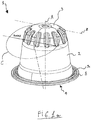
- the attached figures show the capsule 1 according to an exemplary embodiment of the present invention, for the preparation of a beverage, such as coffee, tea, hot and cold drinks, or any other liquid foodstuff, from a pre-determined amount of an extractable or soluble or dilutable product, either liquid or solid, contained inside the capsule.
- a beverage such as coffee, tea, hot and cold drinks, or any other liquid foodstuff
- the dose of product comprise a granular or minced powder product, such as coffee powder or tea leaves, which are brewed by means of brewing liquid, preferably hot water under pressure, that is injected into the capsule for obtaining the desired beverage.
- the capsule according to the invention is used into a beverage preparation device (i.e. a brewing device), schematically shown in figures 3 , 3a and 3b , provided with an enclosing member, or receptacle 41, intended to house at least part of the capsule during the beverage preparation process.
- the brewing device can be further provided with piercing means 42, for example one or more blades or similar elements for piercing the capsule, preferably in correspondence of the water inlet wall of the capsule (inlet wall) in order to feed the brewing liquid, preferably hot water under pressure, inside the capsule. While specific reference will be made to water, it has to be noted that the capsule according to the invention can be used with brewing liquid of different types.
- some of the piercing means of the brewing device are schematically shown in figures 2 and 3 .
- piercing means 42 of the brewing device can be provided, such as for example blades arranged along a circular line.
- a new type of brewing device recently marketed, comprises piercing means, i.e. blades, provided with two flat portions arranged to each other at substantially 90°. According to this shape, the blades are arranged so as they can contact the inlet wall of the capsule along an annular portion, i.e. an annular piercing area.
- the area of the inlet wall of the capsule that can be contacted by the blades can be seen as a circular line, or an annular portion, substantially corresponding to the circular line or the annular shape along which the piercing means of the brewing device are arranged.
- the inlet wall 3 of the capsule is provided with at least one piercing area 6 that is extending along a circular line, or along an annular portion, on the inlet wall 3.
- the at least one piercing area is arranged between the central axis A and the peripheral edge 2c of the inlet wall 3, i.e. the boundary line between the inlet wall 3 and the lateral wall 2.
- the brewing water under pressure is injected into the capsule in a known way, e.g. by injection means of the brewing device comprising for example a water pump, not shown in the attached figures.
- the capsule 1 according to the invention can be an open capsule, i.e. provided with one or more apertures intended to allow the injection of the brewing liquid inside the capsule. It has to be noted that even if the brewing device is provided with piercing means 42, the capsule according to the invention can be open, i.e. provided with one or more inlet openings and the shape of at least one portion of the inlet wall described herein below allows maximizing the internal volume of the capsule and to allow the insertion inside the brewing device, thus avoiding the capsule to be blocked inside it.
- a closed capsule i.e. a capsule having a closed inlet wall that is intended to be pierced by piercing means of the beverage preparation device inside which the capsule is inserted.
- the capsule according to the invention is preferably made by thermoplastic material, however at least part of the capsule can be made of aluminium.
- the capsule, and in particular its inlet wall 3 can be provided with a membrane or foil intended to cover one or more opening provided on the inlet wall.
- the capsule 1 comprises a lateral wall 2, a water inlet wall 3 and an outlet wall 4, said walls defining a hollow body 5 where the dose of product is located.
- the water inlet wall 3 is the inlet surface of the capsule and is intended to be perforated by the piercing means 42 of the brewing device to obtain inlet apertures allowing the passage of the brewing liquid into the capsule, if the capsule is a closed capsule.
- the outlet wall 4 allows the exit of the brewed beverage from the capsule into a container and the outlet means of the capsule, i.e. the elements allowing the exit of the brewed beverage, can be made in different ways.
- the outlet wall 4, or the wall comprising the outlet from which the beverage exits the capsule, can be a separate element which is connected to the lower portion of the capsule body 5, in order to close the capsule.
- outlet wall 4 Any suitable constraint means of the outlet wall 4 to the capsule body 5 can be used, and in other possible embodiments the outlet wall 4 may be produced in one piece with the capsule's lateral wall 2.
- the outlet wall may be produced in different material with respect to the capsule material, for example, the outlet wall 4 may be a preferably non porous membrane, for instance an aluminium or a laminated foil, preferably a laminated foil including aluminium, as shown in the sectional view of figure 2 .
- suitable materials are a paper filter, a non-woven fabric or a cap in thermoplastic or similarly rigid or semirigid material provided with holes, as already known in other capsules for the production of beverage.
- the outlet means may comprise self-perforating elements that are broken under mechanical and/or pressure force acting on the capsule, or one or more holes that are produced by piercing means of the brewing device.
- outlet means may include open passages.
- the self-perforating element suitable for the outlet wall 4 is protruding from the lower surface of the outlet wall 4, and is defined by grooves, or lines with reduced thickness, that are breakable under the action of the mechanical force exerted by the brewing device and/or the force exerted by the water fed into the capsule.
- these means can be used on the inlet wall 3 of the capsule, which can be provided with one or more breakable areas.
- outlet means can be provided, i.e. the extraction of the beverage from the capsule can be obtained, for example, by perforating the capsule by suitable piercing means of the brewing device; in another embodiment, the outlet means is a water-soluble membrane.
- the capsule 1 has a central axis A (vertical axis) passing through the inlet wall 3 and the outlet wall 4.
- the later wall 2 can be at least in part circular or conical, i.e. the lateral wall 2 can be parallel or inclined with respect to the central axis A, along its extension between the outlet wall 4 and the inlet wall 3.
- the body 5 of the capsule is provided with a cup-shape, or a frustoconical shape, in other words the lateral wall 2 is not parallel to the central axis A and the hollow body 5 is closed by the outlet wall 4 at one end and by the inlet wall 3 at the opposite end of the lateral wall with respect to the outlet wall 4.
- the body 5 of the capsule having a lateral wall 2 that is at least in part circular or conical with respect to the central axis A is provided with circular cross sections along planes perpendicular with respect to the central axis A of the capsule.
- the lateral wall 2 of the capsule is formed by inclined surfaces arranged one next to another, in general it forms a circular or conical lateral wall 2 that can be inscribed in a circumference (circular line).
- a circular or conical lateral wall 2 also encompassing embodiments wherein the lateral wall 2 of the capsule is made by a plurality of inclined surface, forming polygonal cross sections along planes perpendicular with respect to the central axis A, that can be inscribed into a circumference.
- the lateral wall 2 comprises a peripheral edge 2c, and the water inlet wall 3 extends between the peripheral edge 2c and the central axis A.
- the thickness t1 of the inlet wall 3 is preferably constant along its extension from the central axis A towards the lateral wall 2.
- the thickness t1 of the inlet wall is constant except for the one or more areas on its surface where reinforcing means 50, for example in the form of ribs, are arranged.
- the reinforcing means are in the forms of recess portions 51 the thickness of the recess portion is preferably the same as the thickness of the inlet wall 3 outside the recess.
- the thickness t1 of the inlet wall 3 is equal to, or lower than, the thickness t2 of the lateral wall 2 of the capsule.
- the lateral wall 2 can be provided with different thickness along its extension between the inlet wall 3 and the outlet wall 4 (as for example in the embodiment shown in figure 2 ).
- the thickness t1 of the inlet wall is equal to, or lower than, the maximum thickness of the lateral wall 2.
- the maximum thickness of the inlet wall 3 is equal to, or lower than, the maximum thickness of the lateral wall 2.
- the thickness of the lateral wall 2 and of the inlet wall 3 is comprised in the range 1.6mm - 0.15mm, and preferably in the range 1.2mm - 0.2mm. In a preferred embodiment, the thickness t1 of the inlet wall 3 is 0.2 - 0.5mm.
- the capsule is further provided with a flange-like rim 8 extending from the capsule, preferably in correspondence of the bottom end of the lateral wall 2 in correspondence of outlet wall 4.
- Sealing means 9 can be provided on the flange-like rim 8, protruding therefrom, for providing a seal-tight engagement with the receptacle 41 of the brewing device when the capsule is used.
- a sealing element 9 is provided on the flange-like rim 8 of the capsule, i.e. the portion of the capsule designed to be brought in contact with the receptacle 41 of the brewing device, and in particular with the lower circular edge 41a of the receptacle, i.e. the pressing portion of the receptacle 41, for providing the sealing engagement.
- the sealing member 9 is produced in one piece with the flange 8 and it is shaped as an element protruding from the upper surface of the flange 8 of the capsule.
- the water inlet wall 3 is shaped to facilitate both the insertion of the capsule into the receptacle 41 of the brewing device and the maximization of the internal volume of the capsule.
- the shape of the inlet wall allows the perforation of the inlet wall 3 by piercing means 42 of the brewing device.
- the shape of the inlet wall 3 of the capsule according to the invention that comprises at least one portion extending along an ellipse curve E defined circumference C (circular line) (shown in figure 1a ) having the diameter substantially equal to the maximum diameter Dmax of the lateral wall 2 of the capsule that lies on a plane P' (see figures 1a and 1b ) that is inclined with respect to a plane P, perpendicular with respect to the central axis A of the capsule.
- the circumference C is projected on a plane perpendicular with respect to said plane P and passing through an intersection axis z between said planes P and P', or through an axis parallel to the intersection axis z.
- the plane on which the circumference C is projected is a plane passing through the central axis A and the intersection axis z, as shown in figure 2 .
- at least part of the inlet wall 3 that is extending between the central axis A and the lateral wall 2 is shaped as an ellipse curve E seen on a plane perpendicular to the plane P and passing through the intersection axis z, or through an axis parallel to the axis z.
- the plane on which the circumference C is projected is a plane passing through the central axis A of the capsule, for example a radial plane from which the section view of figure 2 is taken, and passing through the axis z, or an axis parallel to the axis z.
- the plane P' on which the circumference C lies is inclined with respect to the plane P, perpendicular with respect to the central axis A, about the intersection axis z passing trough said planes P' and P and perpendicular with respect to the central axis A, see figure 1a .
- the ellipse curve E can be seen as the projection of the circumference lying on the plane P', on a plane perpendicular to the plane P and passing through the axis z, or an axis parallel to the axis z.
- the plane on which the circumference is projected can pass through the central axis A of the capsule and the axis z (as in the embodiment shown in figure 2 that is a section view from the plane on which the ellipse is projected), i.e. on a radial plane passing through the central axis A of the capsule and the intersection axis z.
- the inlet wall 3 is at least in part extending along the ellipse curve E.
- the ellipse curve E forms a upper boundary line for the inlet wall 3 that is at least in part following said ellipse curve E, or arranged below said ellipse curve E, as for example shown in figure 2 .
- the inlet wall 3 is at least in part extending along said ellipsoid surface.
- the shape of the inlet wall 3, and preferably the at least one portion extending along an ellipse curve E, is equal at least in the 80%, more preferably the 95%, and most preferably in the 100% of radial sections taken on planes passing through said central axis A along of the circular extension of the capsule lateral wall 2.
- the shape of the inlet wall 3 seen in a section view along a radial plane passing through the central axis A of the capsule, is constant along the circular extension of the capsule. More in details, the 80%, more preferably the 95%, and most preferably in the 100% of the radial section of the capsule, the shape of the inlet wall is the same.
- the reinforcing means 50, 51 can be provided only in some radial sections of the capsule taken along radial planes passing through the central axis A, are not taken into account.
- the above reported percentage relates to the inlet wall shape except for the reinforcing means 50, 51, for example in the form of recess portion or ribs, provided on it.
- the circumference C having a diameter equal to the maximum diameter Dmax of the lateral wall 2 of the capsule lies on a plane P' that is inclined at an angle ⁇ with respect to a plane P perpendicular with respect to the central axis
- the angle ⁇ can be comprised in the range 15° - 44°, preferably 15°-30° and more preferably 16°-25°
- the angle ⁇ is comprised in the range 18° - 22°, and preferably in the range 19° - 21 °, and most preferably the angle ⁇ is about 20°.
- the angle ⁇ of inclination of said plane P' and said plane P perpendicular with respect to the central axis A of the capsule is substantially equal to the angle of inclination ⁇ between the central axis of the capsule A and the axis X along which the receptacle 41 of the brewing device is movable.
- the circumference C having diameter equal to the maximum diameter of the capsule's lateral wall 2 lying on a plane P' inclined with respect to a plane P which is perpendicular to the central axis A of the capsule, and that is further projected on plane perpendicular to the plane P and passing through the axis z, or a an axis parallel to the axis z, allows to provide an effective insertion of the capsule inside the receptacle 41 of the brewing device.
- the angle ⁇ of inclination between the plane P' on which the circumference lies and the plane P, perpendicular with respect to the central axis A of the capsule substantially corresponds to the angle ⁇ of inclination of the central axis A of the capsule, when it is inserted into the brewing device, and the axis X along which the receptacle is movable.
- said circumference C having a diameter equal to the maximum diameter of the capsule's lateral wall 2 can be seen as a circumference corresponding to the pressing circular edge 41a of the receptacle 41 of the brewing device, see herein below for further detail where the beverage preparation system according to the invention is described.
- the maximum diameter Dmax of the lateral wall 2 of the capsule is comprised in the range 27mm - 33mm, preferably 28mm - 32mm, more preferably, 29mm - 31mm and most preferably is about 30mm.
- the maximum diameter Dmax of the lateral wall of the capsule is substantially equal to, or slightly less than, the diameter DR of the circular pressing edge 41a of the receptacle 41 of the brewing device inside which the capsule is inserted.
- the ellipse curve E is arranged with its minor axis E1 substantially coincident with the central axis A and is tangent to the highest point, or area 3a, of the inlet wall 3 with respect to the outlet wall 4.
- the minor axis E1 is substantially coincident with the central axis A
- the minor axis of the ellipse curve E can be also arranged parallel and close to the central axis A of the capsule, and/or slightly inclined with respect to the central axis A of the capsule.
- the highest point or area 3a of the inlet wall is used herein to indicate the area of the inlet wall that is arranged at maximum distance H from the outlet wall 4.
- the plane P perpendicular with respect to the central axis A of the capsule is tangent to the highest point or area 3a of the inlet wall 3 of the capsule.
- the distance H between the highest point, or area 3a, of the inlet wall 3 and the outlet wall 4 is comprised in the range 26mm - 30mm, preferably 27mm - 29mm, and more preferably is about 28mm.
- the distance H of the highest point, or area 3a, of the inlet wall 3 from the outlet wall 4 identifies the height of the capsule 1.
- distance H between said highest point, or area 3a, of the inlet wall 3 and the outlet wall 4 is selected so as the capsule can be inserted into the brewing device.
- the distance H between the highest point or area 3a of the capsule and the outlet wall 4 is less than the distance H1 between the surface 45 along which the outlet wall 4 is moved when the capsule is inserted inside the brewing device, and the first portion 41 of the pressing edge 41a of the receptacle 41 of the brewing device encountered by the highest point, or area 3a, of the inlet wall 3 with respect to the outlet wall 4, when the receptacle is in an open position for the insertion of the capsule.
- the distance H1 between the surface 45, i.e. the plane formed by suitable guide means of the brewing device, along which the outlet wall of the capsule is moved when the capsule is inserted inside the brewing device, and the first portion 41c encountered by the capsule, is measured along axis perpendicular with respect to the surface 45 and in general with respect to the outlet wall 4 of the capsule (as shown in figure 3a ).
- first portion encountered is meant the portion of the receptacle 41 that is first encountered by the capsule, and preferably by the capsule inlet wall, when the capsule is inserted inside the brewing device and the receptacle is in open position.
- the capsule is inserted from above with respect to the brewing device and the first portion of the receptacle encountered by the inlet wall of the capsule is the upper edge 41c of the circular pressing edge 41a, i.e. the edge passing through a vertical diameter of the receptacle (see figure 3a ).
- the inlet wall 3 is extending along the ellipse curve E, substantially from the central axis A to the piercing area 6, and preferably from the central axis A to the closest end part 6a of the piercing area 6 with respect to the central axis A.
- end part 6a of the piercing area 6 closest to the central axis A of the capsule is meant the at least one point, or area, of the piercing area 6 nearest to the central axis A of the capsule.
- the piercing area 6 is preferably circular or annular shaped, and the closest end part 6a of the piercing area corresponds to the circular line itself, or to the closest circular line of the annular piercing area with respect to the central axis A.
- the elliptic shape of the inlet wall at least in the area between the central axis A and the closest end part 6a of the piercing area 6 with respect to the central axis A of the capsule was found particularly advantageous in some experimental tests carried out by the Applicant.
- the described elliptic shape of the inlet wall allows to increase the internal volume of the capsule and at the same time to provide an effective perforation of the inlet wall 3.
- the ellipse curve E is not followed by the inlet wall 3 in correspondence of the area around the central axis A, as for example in the embodiment shown in the figures, wherein the inlet wall 3 comprises a substantially flat top portion 3b.
- the inlet wall 3 is provided with a top portion 3b that is substantially flat.
- the flat top portion is preferably used as injection point for the moulded material in the production process of the capsule.
- the inlet wall 3 is extending along the ellipse curve E between the highest point, or area 3a, of the inlet wall 3 with respect to the outlet wall 4, and the closest end part 6a of the piercing area 6 with respect to the central axis A.
- the highest point 3a of the inlet wall is arranged between the central axis A and the closest end part 6a of the piercing area 6 with respect to the central axis A.
- the inlet wall 3 comprises at least one portion 3b, 3c that is not extending along the ellipse curve E.
- the portion 3b, 3c of the inlet wall 3 that is not extending along the ellipse curve E is arranged below the ellipse curve E.
- the shape of the inlet wall 3 is also influenced by the shape of the receptacle 41 of the brewing device inside which the capsule is inserted during the beverage preparation process.
- the at least one portion 3c extending below the ellipse curve E can be a portion of the inlet wall 3 arranged between the piercing area 6 and the lateral wall 2.
- said portion 3c extending below the ellipse curve E is arranged between the closest end part 6a of the piercing area 6 and the lateral wall 2.
- the capsule can be further provided with reinforcing means 50, 51 in order to increase the rigidity of the inlet wall 3 and/or of the lateral wall 2, thus facilitating the perforation of the inlet wall.
- the reinforcing means 50, 51 can extend on the inlet wall 3 and/or on the lateral wall 2.
- the reinforcing means can be shaped in the form of at least one recess portion 51 completely contained within the inlet wall 3, or extending on both the lateral wall 2 and the water inlet wall 3.
- the reinforcing means can be shaped in the form of one or more ribs 50 protruding from the water inlet wall 3 surface and arranged circumferentially and/or radially on the water inlet wall 3.
- the capsule 1 comprises at least one rib 50 and/or at least one recess portion 51 extending on the inlet wall 3 and/or on the lateral wall 2 of the capsule.
- the capsule according to the invention can be provided with reinforcing means comprising at least one, preferably a plurality of recess portions 51 extending on both the inlet wall 3 and on the lateral wall 2 and connecting together areas of said walls.
- the capsule is provided with at least one recess portion 51 forming a corrugation in correspondence of the peripheral edge 2c of the lateral wall 2.
- the at least one recess portion 51 defines a modification of the shape of both the inlet wall 3 and of the lateral wall 2 in correspondence of the peripheral edge 2c of the lateral wall 2 from which the inlet wall 3 extends.
- Recess portion 51 comprises at least one surface connecting the lateral wall to the inlet wall of the capsule and forming an additional wall that connects lateral and inlet walls 2, 3.
- Preferred embodiments of a capsule having recess portions are disclosed in pending application PCT/IB2012/0028 .
- the at least one recess portion 51 comprises at least one surface, preferably the bottom surface of the recces portion, that lies on a plane K (see figure 1 ) or it contains at least one axis B maintaining a constant angle of inclination with respect to the central axis A of the capsule, or with respect to a vertical axis parallel to the central axis.
- the plane K or the at least one axis B of the surface are directed towards and/or intersect the central axis A of the capsule or a vertical axis parallel to the central axis A.
- the at least one surface of the recess portion that maintains a constant angle of inclination with respect to the central axis A of the capsule or a vertical axis is the bottom surface of the recess portion, preferably extending between the closest and the farthest end parts of the recess portion 51, with respect to the central axis A of the capsule.
- This surface is preferably flat, in fact, said surface lies on a plane K or it contains at least one straight line B (axis).
- the at least one surface of the recess portion preferably maintains a constant angle of inclination with respect to the central axis A of the capsule, or to an axis parallel to it, along its complete extension.
- the inclined surface forms an acute angle with the vertical, i.e. with respect to a direction parallel to the central, vertical rotational axis, i.e. the longitudinal axis A of the capsule, or, more simply, with axis A.
- the acute angle as defined above, is comprised in the range 10° - 75°, preferably 25°- 60°, most preferably about 35°-50°.
- the number of the recess portion can be varied according to different possible embodiments.
- the number of recess portion 51 is not equal to the number of the piercing means (piercing blades) of the brewing device in which the capsule is used and in particular the number of the recess portion 51 is not divisible for the number of piercing means 42 of the brewing device.
- the capsule 1 can be provided with a plurality of ribs 50 protruding from the internal, or external, surface of the inlet wall 3.
- the ribs 50 are preferably arranged in a radial manner from the internal central surface of the inlet wall 3, substantially from the central axis A.
- the ribs are arranged in area of the inlet wall comprised between the central axis A and the closest end 6a of the piercing area 6.
- the capsule is provided with vertical lugs 60 (see figure 2 ) protruding from the internal surface of the lateral wall 2 and intended to impede the capsules from stacking during the production process. Thickness, shape and radius of such lug(s) will vary depending on the chosen manufacturing methods, to be selected amongst the ones mentioned earlier, as it can easily inferred by the skilled in the art.
- Vertical lugs 60 can extend on both the inlet and lateral walls 3 and 2, or they can be provided only on the lateral wall 2 of the capsule.
- the capsule 1 according to the invention can be used in a beverage preparation device (brewing device), thus providing a system for the beverage preparation.
- the brewing device schematically shown in figures 3 , 3a and 3b , comprises a receptacle 41 for housing at least part of said capsule.
- both open capsule and closed capsule according to the invention can be used in the system, even if in the following specific reference will be made to closed capsule.
- the brewing device can be further provided with piercing means 42 for piercing said capsule inlet wall 3 in correspondence of the at least one piercing area 6,
- the receptacle 41 of the brewing device is moved with respect to the capsule 1, and/or vice versa, so that a seal-tight engagement with the capsule 1 (preferably at the flange-like rim 8) can be obtained and the piercing means 42 are brought in contact with the capsule.
- a closed capsule is perforated in correspondence of the piercing area 6 of the inlet wall 3 of the capsule.
- the receptacle 41 is movable along an axis X, that is preferably horizontal, between an open position (shown in figures 3 , 3a and 3b ) in which the capsule can be inserted into the brewing device and a closed position (not shown) wherein the capsule is housed inside the receptacle.
- the capsule 1 is arranged inside the brewing device with its central axis A inclined at an angle ⁇ with respect to the axis X along which the receptacle is movable (see the lateral view of figure 3a ).
- inclined guides (schematically shown in figures 3 , 3a and 3b ) are provided to form a sliding surface 45 to insert the capsule inside the brewing device with its central axis A inclined with respect to the axis X of movement of the receptacle 41.
- said inclined guides cooperates with the flange-like rim 8 of the capsule to provide such an inclined position of the central axis A with respect to the axis X along which the receptacle is movable. Notwithstanding this, generic reference to a surface 45 along which the outlet wall 4 of the capsule will be used.
- the angle ⁇ between the central axis A and the movement axis X of the receptacle 41 is substantially equal to the angle ⁇ between the plane P' on which the circumference C having the diameter substantially equal to the maximum diameter Dmax of the lateral wall 2 lies, and the plane P perpendicular with respect to the central axis of the capsule.
- the circumference C having a diameter equal to the maximum diameter of the capsule's lateral wall 2, used to define the ellipse curve E, can be seen to substantially correspond to the pressing circular edge 41a of the receptacle 41 of the brewing device.
- the central axis A is inclined at an angle ⁇ with respect to the axis X of the direction of movement of the receptacle 41 (see for example the schematic views of figures 3 , 3a and 3b ).
- the angle ⁇ used in known brewing device is comprised in the range 15° - 44°, preferably 15°-30° and more preferably 16°-25°.
- the angle ⁇ is comprised in the range 18° - 22°, and preferably in the range 19° - 21 °, and most preferably the angle ⁇ is about 20°.
- the circumference C corresponding to the circular pressing edge 41a of the brewing device lies on a plane P' that is inclined with respect to a plane P that is perpendicular with respect to the central axis A of the capsule.
- the circumference C corresponding to the circular pressing edge 41a, projected from said plane P' on a plane perpendicular with respect to the plane P and passing through the intersection axis z between planes P and P', or an axis parallel to the axis z, defines the ellipse curve E.
- figure 3b shows the capsule and the receptacle 41 from a plane A-A indicated in figure 3a , that is perpendicular to plane P and passing through an axis parallel to the axis z.
- the pressing edge 41a corresponds to said ellipse curve E.
- the plane on which the circumference C is projected can be a plane passing through the central axis A of the capsule and the intersection axis z, or an axis parallel to the axis z.
- the circular pressing edge 41a of the receptacle is visible on a plane A-A parallel to the central axis A of the capsule and passing through an axis parallel to the axis z, when it is inserted in the brewing device according to the invention.
- the plane through which the circular edge 41a is visible is inclined at an angle ⁇ with respect to the axis X of movement of said receptacle 41.
- the circular pressing edge 41a of the receptacle 41 seen on this plane A-A is an ellipse curve E.
- the axis X is passing through the centre of the circular pressing edge 41a of the receptacle.
- the diameter DR of the pressing circular edge 41a is substantially equal to the maximum diameter Dmax of the lateral wall 2 of the capsule.
- the distance H between the highest point, or area 3a, of the inlet wall 3 and the outlet wall 4 of the capsule 1 is selected so as the capsule 1 can be inserted into the brewing device when the receptacle is the open position
- the distance H between said highest point, or area 3a, of said inlet wall 3 and the outlet wall 4 is less than the distance H1 between the surface 45 along which the outlet wall 4 is moved when the capsule is inserted inside the brewing device, and the first portion 41c of the pressing edge 41a of the receptacle 41 of the brewing device encountered by the highest point, or area 3 a, of the inlet wall 3 with respect to the outlet wall 4, when the receptacle is in the open position for the insertion of the capsule.
- the distance H may be selected so that the highest point 3a, or area, of the inlet wall 3 does not contact the upper surface 41b of the receptacle 41, when the receptacle is in said closed position and the capsule is housed inside the receptacle.
Landscapes
- Engineering & Computer Science (AREA)
- Mechanical Engineering (AREA)
- Food Science & Technology (AREA)
- Life Sciences & Earth Sciences (AREA)
- Chemical & Material Sciences (AREA)
- Polymers & Plastics (AREA)
- Apparatus For Making Beverages (AREA)
- Packging For Living Organisms, Food Or Medicinal Products That Are Sensitive To Environmental Conditiond (AREA)
- Devices For Dispensing Beverages (AREA)
Claims (16)
- Kapsel (1) zur Zubereitung eines Getränks aus einer Brühvorrichtung, wobei die Kapsel umfasst eine kreisförmige oder konische Seitenwand (2), eine Wassereinlasswand (3) und eine Auslasswand (4) aufweist, die einen ein Brühprodukt enthaltenden Hohlkörper (5) ausbildet, wobei der Hohlkörper (5) der Kapsel eine durch die Einlasswand (3) und die Auslasswand (4) verlaufende, Zentralachse (A) aufweist, dadurch gekennzeichnet,
dass sich mindestens ein Teil der Einlasswand (3) entlang einer durch die Projektion eines kreisförmigen Umfangs (C) definierten Ellipsenkurve (E) erstreckt,
wobei der Umfang (C) einen Durchmesser aufweist, der im Wesentlichen dem maximalen Durchmesser (Dmax) der Seitenwand (2) der Kapsel entspricht, und der in einer Ebene (P') liegt, welche gegenüber einer zur Zentralachse (A) der Kapsel senkrechten Ebene (P) in einem Winkel (α) geneigt ist, wobei die Ebenen (P) und (P') sich entlang einer Achse (z) schneiden, wobei die durch den Mittelpunkt des in der Ebene (P') liegenden Umfangs (C) verlaufende Achse bezüglich der Zentralachse (A) der Kapsel im Winkel (α) geneigt ist, wobei der Umfang (C) auf eine Ebene projiziert wird, die senkrecht zur Ebene (P) steht und die zum Erhalt der Ellipsenkurve (E) eine Achse ausgewählt aus der Schnittachse (z) oder einer zur Schnittachse (z) parallelen Achse umfasst, wobei die Ellipsenkurve (E) eine Tangente an die Einlasswand (3) am höchsten Punkt, oder Bereich (3a), der Einlasswand (3) relativ zur Auslasswand (4) ist, und wobei der Winkel (α) im Bereich von 15° bis 44° liegt, vorzugsweise im Bereich von 18° bis 22°, und besonders bevorzugt im Bereich von 19° bis 21 °, und am bevorzugtesten bei etwa 20°. - Kapsel gemäß Anspruch 1, wobei die Ellipsenkurve (E) so angeordnet ist, dass ihre Nebenachse (E1) im Wesentlichen mit der Zentralachse (A) zusammenfällt.
- Kapsel gemäß einem der vorhergehenden Ansprüche, wobei wenigstens ein sich entlang der Ellipsenkurve (E) erstreckender Teil der Einlasswand (3) zwischen der Zentralachse (A) und einer peripheren Kante (2c) zwischen der Einlasswand (3) und der Seitenwand (2) umfasst ist.
- Kapsel gemäß einem der vorhergehenden Ansprüche, wobei die Einlasswand (3) wenigstens einen, zum Kontakt mit Einstechmitteln (42) der Brühvorrichtung bestimmten Einstechbereich (6) aufweist, wobei der wenigstens eine, sich entlang der Ellipsenkurve (E) erstreckende Teil der Einlasswand (3) im Wesentlichen zwischen der Zentralachse (A) und dem Einstechbereich (6), vorzugsweise zwischen der Zentralachse (A) und dem bezüglich der Zentralachse (A) nächstgelegenen Endbereich (6a) des Einstechbereichs (6) umfasst ist.
- Kapsel gemäß einem der vorhergehenden Ansprüche, wobei die Ellipsenkurve (E) eine Hauptachse (E2) aufweist, die im Wesentlichen dem maximalen Durchmesser (Dmax) der Seitenwand (2) der Kapsel entspricht, und eine Nebenachse (E1) aufweist, die dem maximalen Durchmesser (Dmax) der Seitenwand (2) multipliziert mit dem Sinus des Winkels (α) gemäß der mathematischen Formel E1 = Dmax * sin(α) entspricht.
- Kapsel gemäß einem der vorhergehenden Ansprüche, wobei der maximale Durchmesser (Dmax) der Seitenwand (2) der Kapsel im Bereich von 27 mm bis 33 mm liegt, vorzugsweise im Bereich von 28 mm bis 32 mm, noch bevorzugter im Bereich von 29 mm bis 31 mm, und am meisten bevorzugt bei etwa 30 mm.
- Kapsel gemäß einem der vorhergehenden Ansprüche, wobei der Abstand (H) zwischen dem höchsten Punkt, oder Bereich (3a), der Einlasswand (3) und der Auslasswand (4) im Bereich von 26 mm bis 30 mm liegt, vorzugsweise im Bereich von 27 mm bis 29 mm, und noch bevorzugter bei etwa 28 mm.
- Kapsel gemäß einem der vorhergehenden Ansprüche, wobei die Form der Einlasswand (3) wenigstens zu 80%, bevorzugter zu 95% und am bevorzugtesten zu 100% den Radialabschnitten entspricht, entnommen aus durch die Zentralachse (A) entlang der kreisförmigen Erstreckung der Kapsel-Seitenwand (2) verlaufenden Ebenen.
- Kapsel gemäß einem der vorhergehenden Ansprüche, wobei die Einlasswand (3) wenigstens einen Abschnitt (3b, 3c) umfasst, der sich unterhalb der Ellipsenkurve (E) erstreckt, wobei der wenigstens eine, sich unterhalb der Ellipsenkurve (E) erstreckende Abschnitt (3b, 3c) zwischen wenigstens einem Abschnitt des Einstechbereichs (6) und der Seitenwand (2) und/oder korrespondierend zur Zentralachse (A) der Kapsel angeordnet ist.
- Kapsel gemäß einem der vorhergehenden Ansprüche, wobei der Umfang (C), welcher einen Durchmesser aufweist, der im Wesentlichen dem maximalen Durchmesser (Dmax) der Seitenwand (2) der Kapsel entspricht, und welcher in einer, in einem Winkel (α) gegenüber einer zur Zentralachse (A) der Kapsel senkrechten Ebene (P) geneigten Ebene (P') liegt, mit einer kreisförmigen Presskante (41a) einer Aufnahme (41) der Brühvorrichtung übereinstimmt, in welche die Kapsel eingesetzt wird.
- Kapsel gemäß einem der vorhergehenden Ansprüche, wobei der Abstand (H) zwischen dem höchsten Punkt, oder Bereich (3a), der Einlasswand (3) und der Auslasswand (4) geringer ist als der Abstand (H1) zwischen der Oberfläche (45), entlang der die Auslasswand (4) beim Einführen der Kapsel in die Brühvorrichtung bewegt wird, und dem ersten Abschnitt (41c) der Presskante (41a) der Brühvorrichtungs-Aufnahme (41), welcher Abschnitt mit dem höchsten Punkt, oder Bereich (3a), der Einlasswand (3) bezüglich der Auslasswand (4) dann in Berührung kommt, wenn sich die Aufnahme zum Einführen der Kapsel in einer offenen Position befindet.
- System zum Zubereiten eines Getränks, umfassend eine Kapsel gemäß einem der Ansprüche 1 bis 11 und eine Brühvorrichtung mit einer Aufnahme (41) zum Aufnehmen wenigstens eines Teils der Kapsel, wobei die Aufnahme (41) entlang einer Achse (X) beweglich ist zwischen einer offenen Position, in der die Kapsel in die Brühvorrichtung eingeführt werden kann, und einer geschlossenen Position, in der die Kapsel innerhalb der Aufnahme (41) aufgenommen ist, wobei die Aufnahme (41) eine kreisförmige Presskante (41a) umfasst.
- System gemäß Anspruch 12, wobei die kreisförmige Presskante (41a) der Aufnahme (41) einen Durchmesser (DR) aufweist, der im Wesentlichen dem maximalen Durchmesser (Dmax) der Seitenwand (2) der Kapsel entspricht und in einer Ebene (P') liegt, die bezüglich einer zur Zentralachse (A) der Kapsel senkrechten Ebene (P) in einem Winkel (α) geneigt ist.
- System gemäß Anspruch 12 oder 13, wobei die Kapsel (1) innerhalb der Brühvorrichtung angeordnet ist, wobei die Zentralachse (A) bezüglich der Achse (X), entlang derer die Aufnahme beweglich ist, in einem Winkel (γ) geneigt ist, wobei der Winkel (γ) vorzugsweise im Wesentlichen dem Winkel (α) entspricht.
- System gemäß einem der Ansprüche 12 bis 14, wobei der Abstand (H) zwischen dem höchsten Punkt, oder Bereich (3a), der Einlasswand (3) und der Auslasswand (4) der Kapsel (1) so ausgewählt ist, dass die Kapsel (1) in die Brühvorrichtung eingeführt werden kann, wenn sich die Aufnahme in der offenen Position befindet, wobei der Abstand (H) zwischen dem höchsten Punkt, oder Bereich (3a), der Einlasswand (3) und der die Auslasswand (4) vorzugsweise kleiner ist als der Abstand (H1) zwischen der Oberfläche (45), entlang der die Auslasswand (4) beim Einführen der Kapsel in die Brühvorrichtung bewegt wird, und dem ersten Abschnitt (41c) der Presskante (41a) der Brühvorrichtungs-Aufnahme (41), welcher Abschnitt mit dem höchsten Punkt, oder Bereich (3a), der Einlasswand (3) bezüglich der Auslasswand (4) dann in Berührung kommt, wenn sich die Aufnahme zum Einführen der Kapsel in einer offenen Position befindet.
- System gemäß einem der Ansprüche 12 bis 15, wobei der Abstand (H) zwischen dem höchsten Punkt, oder Bereich (3a), der Einlasswand (3) und der Auslasswand (4) der Kapsel (1) so gewählt ist, dass der höchste Punkt, oder Bereich (3a), der Einlasswand (3) die obere Fläche (41b) der Aufnahme (41) nicht berührt, wenn sich die Aufnahme in der geschlossenen Position befindet und die Kapsel in der Aufnahme aufgenommen ist.
Applications Claiming Priority (1)
| Application Number | Priority Date | Filing Date | Title |
|---|---|---|---|
| PCT/EP2013/077226 WO2015090390A1 (en) | 2013-12-18 | 2013-12-18 | Capsule and system for the beverage preparation |
Publications (2)
| Publication Number | Publication Date |
|---|---|
| EP3083449A1 EP3083449A1 (de) | 2016-10-26 |
| EP3083449B1 true EP3083449B1 (de) | 2018-03-07 |
Family
ID=49880758
Family Applications (1)
| Application Number | Title | Priority Date | Filing Date |
|---|---|---|---|
| EP13811915.1A Active EP3083449B1 (de) | 2013-12-18 | 2013-12-18 | Kapsel und system zur herstellung von getränken |
Country Status (10)
| Country | Link |
|---|---|
| US (1) | US10196201B2 (de) |
| EP (1) | EP3083449B1 (de) |
| JP (1) | JP6343007B2 (de) |
| KR (1) | KR20160105806A (de) |
| CN (1) | CN106029527A (de) |
| AU (1) | AU2013407942B2 (de) |
| CA (1) | CA2933700A1 (de) |
| ES (1) | ES2671768T3 (de) |
| RU (1) | RU2638146C1 (de) |
| WO (1) | WO2015090390A1 (de) |
Families Citing this family (13)
| Publication number | Priority date | Publication date | Assignee | Title |
|---|---|---|---|---|
| US11832755B2 (en) * | 2007-07-13 | 2023-12-05 | Adrian Rivera | Brewing material container for a beverage brewer |
| US10722066B2 (en) * | 2010-12-04 | 2020-07-28 | Adrian Rivera | Windowed single serving brewing material holder |
| US10071851B2 (en) | 2010-07-12 | 2018-09-11 | Robert Bao Vu | Apparatus and products for producing beverages, and methods for making and using same |
| KR102318476B1 (ko) * | 2010-07-22 | 2021-11-01 | 카-페 시스템 게엠베하 | 음료수 제조를 위한 1인용 캡슐 |
| US11000148B2 (en) | 2016-06-28 | 2021-05-11 | Berry Plastics Corporation | Beverage-brewing package |
| EP3342730A1 (de) * | 2017-01-02 | 2018-07-04 | Tuttoespresso S.r.l. | Kapsel und verfahren zur herstellung von getränken |
| CN107212755B (zh) * | 2017-07-24 | 2020-07-14 | 深圳鼎加弘思饮品科技有限公司 | 一种饮品胶囊结构及其加速溶解冲泡方法 |
| DE102018105213A1 (de) * | 2018-03-07 | 2019-09-12 | Melitta Single Portions Gmbh & Co. Kg | Vorrichtung und Verfahren zur Herstellung eines Brühgetränks |
| GB201809708D0 (en) * | 2018-06-13 | 2018-08-01 | Obrist Closures Switzerland | Beverage capsule |
| US11805934B1 (en) | 2020-10-21 | 2023-11-07 | Adrian Rivera | Brewing material lid and container for a beverage brewer |
| US12325579B2 (en) | 2020-10-22 | 2025-06-10 | Berry Global, Inc. | Beverage capsule cup with enhanced material distribution |
| TW202322735A (zh) * | 2021-09-30 | 2023-06-16 | 瑞士商雀巢製品股份有限公司 | 飲料或食物容器及製備系統 |
| TW202327498A (zh) * | 2021-09-30 | 2023-07-16 | 瑞士商雀巢製品股份有限公司 | 飲料或食物製備系統 |
Citations (2)
| Publication number | Priority date | Publication date | Assignee | Title |
|---|---|---|---|---|
| EP1894854A2 (de) * | 2006-08-30 | 2008-03-05 | Nestec S.A. | Kapsel zum Brühen eines Getränks |
| WO2013046189A1 (en) * | 2011-09-29 | 2013-04-04 | Novacart S.P.A. | Paper capsule |
Family Cites Families (20)
| Publication number | Priority date | Publication date | Assignee | Title |
|---|---|---|---|---|
| FR2842092B1 (fr) * | 2002-07-12 | 2004-12-24 | Seb Sa | Machine a cafe fonctionnant avec des doses |
| EP1944248B1 (de) * | 2007-01-15 | 2017-12-13 | Swiss Caffe Asia Ltd. | Kapsel, Mittel zum Penetrieren des Bodens einer Kapsel und Vorrichtung für die Zubereitung eines Getränks |
| EP2280885B2 (de) * | 2008-04-30 | 2017-08-30 | Nestec S.A. | Verschlossene kapsel für getränkebestandteile mit einlassseitiger membran |
| ES2377030T3 (es) * | 2008-07-15 | 2012-03-21 | Nestec S.A. | Procedimiento para la aplicación de un caucho de junta líquido sobre una cápsula |
| JP4278706B1 (ja) * | 2008-08-20 | 2009-06-17 | ユーシーシー上島珈琲株式会社 | 飲料用抽出フィルター及びその製造方法 |
| PL2210826T3 (pl) * | 2009-01-22 | 2013-01-31 | Nestec Sa | Kapsułka ze zintegrowanym członem przebijającym i system do wytwarzania napoju |
| IT1393007B1 (it) * | 2009-03-12 | 2012-04-11 | Emmebielle S R L | Macchina per la preparazione mediante infusione di bevande mediante capsule |
| EP2364930B1 (de) * | 2009-03-19 | 2018-12-05 | Nestec S.A. | Kapsel zur Zubereitung von Kaffee in einer Vorrichtung mit einem Kartuschenhalter mit Aussparung und eingelassenen Elementen |
| JP5763905B2 (ja) * | 2009-10-30 | 2015-08-12 | ネステク ソシエテ アノニム | 水の注入のための穿孔を容易にする構造部を有するコーヒー抽出物の生成のためのカプセル |
| ES2548903T3 (es) | 2010-06-11 | 2015-10-21 | Alain Frydman | Cápsula para la extracción de una bebida a presión |
| EP2394539B1 (de) * | 2010-06-11 | 2013-12-04 | Alain Frydman | Bimaterielle Kapsel |
| WO2011159162A1 (en) * | 2010-06-18 | 2011-12-22 | Biserkon Holdings Ltd. | Capsule, device and method for preparing a beverage by extraction |
| RU2571191C2 (ru) * | 2010-10-08 | 2015-12-20 | Конинклейке Филипс Электроникс Н.В. | Блок заваривания с горизонтальным движением |
| PT2476633E (pt) * | 2010-12-17 | 2013-11-22 | Delica Ag | Cápsula, sistema e método para a preparação de uma bebida |
| EP2681133B1 (de) * | 2011-03-03 | 2016-02-24 | Biserkon Holdings Ltd. | Kapsel |
| JP2014515297A (ja) | 2011-06-01 | 2014-06-30 | フライドマン,アラン | 加圧飲料抽出用カプセル |
| WO2013076519A1 (en) * | 2011-11-22 | 2013-05-30 | Tuttoespresso S.R.L. | Capsule for beverage preparation |
| WO2013120997A1 (de) * | 2012-02-15 | 2013-08-22 | Ritter Gmbh | Ein- und zwei-komponenten-kaffeekapseln |
| US8986763B2 (en) * | 2012-02-27 | 2015-03-24 | Rialto Coffee Company Ltd. | Optimal extraction rate coffee capsule with effective seal for diverse group heads |
| US20130224340A1 (en) * | 2012-02-27 | 2013-08-29 | Hanan BenDavid | Optimal extraction rate coffee capsule with effective seal for diverse group heads |
-
2013
- 2013-12-18 EP EP13811915.1A patent/EP3083449B1/de active Active
- 2013-12-18 AU AU2013407942A patent/AU2013407942B2/en not_active Ceased
- 2013-12-18 WO PCT/EP2013/077226 patent/WO2015090390A1/en not_active Ceased
- 2013-12-18 US US15/106,014 patent/US10196201B2/en active Active
- 2013-12-18 CN CN201380082050.2A patent/CN106029527A/zh active Pending
- 2013-12-18 KR KR1020167018372A patent/KR20160105806A/ko not_active Withdrawn
- 2013-12-18 RU RU2016128915A patent/RU2638146C1/ru not_active IP Right Cessation
- 2013-12-18 JP JP2016539265A patent/JP6343007B2/ja not_active Expired - Fee Related
- 2013-12-18 CA CA2933700A patent/CA2933700A1/en not_active Abandoned
- 2013-12-18 ES ES13811915.1T patent/ES2671768T3/es active Active
Patent Citations (2)
| Publication number | Priority date | Publication date | Assignee | Title |
|---|---|---|---|---|
| EP1894854A2 (de) * | 2006-08-30 | 2008-03-05 | Nestec S.A. | Kapsel zum Brühen eines Getränks |
| WO2013046189A1 (en) * | 2011-09-29 | 2013-04-04 | Novacart S.P.A. | Paper capsule |
Also Published As
| Publication number | Publication date |
|---|---|
| RU2638146C1 (ru) | 2017-12-11 |
| WO2015090390A1 (en) | 2015-06-25 |
| US20170036854A1 (en) | 2017-02-09 |
| JP2017508489A (ja) | 2017-03-30 |
| KR20160105806A (ko) | 2016-09-07 |
| US10196201B2 (en) | 2019-02-05 |
| AU2013407942B2 (en) | 2019-09-12 |
| CA2933700A1 (en) | 2015-06-25 |
| AU2013407942A1 (en) | 2016-07-07 |
| ES2671768T3 (es) | 2018-06-08 |
| JP6343007B2 (ja) | 2018-06-13 |
| CN106029527A (zh) | 2016-10-12 |
| EP3083449A1 (de) | 2016-10-26 |
Similar Documents
| Publication | Publication Date | Title |
|---|---|---|
| EP3083449B1 (de) | Kapsel und system zur herstellung von getränken | |
| EP2882669B1 (de) | Kapsel und system zur herstellung von getränken | |
| EP2437991B1 (de) | Starre patrone für kaffee und lösliche produkte zur getränkezubereitung | |
| WO2013076519A1 (en) | Capsule for beverage preparation | |
| RU2606869C2 (ru) | Картриджи, системы и способы приготовления напитков | |
| EP2287090B1 (de) | Kapsel zur Herstellung eines Kaffeeextrakts mit einer Struktur zur Erleichterung der Perforation zur Einspritzung von Wasser | |
| US10450131B2 (en) | Coffee pod | |
| EP2891615B1 (de) | Kapsel für eine getränkezubereitungsvorrichtung | |
| EP2757055A1 (de) | Kapsel und System zur Herstellung von Getränken | |
| AU2012251460A1 (en) | Device and capsule for preparing a drink | |
| EP2891613B1 (de) | Kapsel zur herstellung eines getränks | |
| CN110431090A (zh) | 用于在低压萃取系统中制备冲泡物或可溶饮料的盒 | |
| EP2886490B1 (de) | Getränkekapsel und System mit verbesserter Wand | |
| WO2018020391A1 (en) | Capsule for the preparation of beverages, having an easily perforable bottom | |
| WO2024167994A1 (en) | Beverage cartridge | |
| HK1164241B (en) | Rigid cartridge for coffee and soluble products for preparing beverages | |
| HK1202501B (en) | Capsule and system for beverage preparation | |
| HK1153715B (en) | Capsule for the preparation of a coffee extract having a structure facilitating perforation for injection of water |
Legal Events
| Date | Code | Title | Description |
|---|---|---|---|
| PUAI | Public reference made under article 153(3) epc to a published international application that has entered the european phase |
Free format text: ORIGINAL CODE: 0009012 |
|
| 17P | Request for examination filed |
Effective date: 20160718 |
|
| AK | Designated contracting states |
Kind code of ref document: A1 Designated state(s): AL AT BE BG CH CY CZ DE DK EE ES FI FR GB GR HR HU IE IS IT LI LT LU LV MC MK MT NL NO PL PT RO RS SE SI SK SM TR |
|
| AX | Request for extension of the european patent |
Extension state: BA ME |
|
| GRAP | Despatch of communication of intention to grant a patent |
Free format text: ORIGINAL CODE: EPIDOSNIGR1 |
|
| INTG | Intention to grant announced |
Effective date: 20170802 |
|
| GRAJ | Information related to disapproval of communication of intention to grant by the applicant or resumption of examination proceedings by the epo deleted |
Free format text: ORIGINAL CODE: EPIDOSDIGR1 |
|
| INTC | Intention to grant announced (deleted) | ||
| GRAR | Information related to intention to grant a patent recorded |
Free format text: ORIGINAL CODE: EPIDOSNIGR71 |
|
| GRAS | Grant fee paid |
Free format text: ORIGINAL CODE: EPIDOSNIGR3 |
|
| GRAA | (expected) grant |
Free format text: ORIGINAL CODE: 0009210 |
|
| INTG | Intention to grant announced |
Effective date: 20180124 |
|
| AK | Designated contracting states |
Kind code of ref document: B1 Designated state(s): AL AT BE BG CH CY CZ DE DK EE ES FI FR GB GR HR HU IE IS IT LI LT LU LV MC MK MT NL NO PL PT RO RS SE SI SK SM TR |
|
| AX | Request for extension of the european patent |
Extension state: BA ME |
|
| REG | Reference to a national code |
Ref country code: GB Ref legal event code: FG4D |
|
| REG | Reference to a national code |
Ref country code: CH Ref legal event code: EP Ref country code: AT Ref legal event code: REF Ref document number: 976297 Country of ref document: AT Kind code of ref document: T Effective date: 20180315 |
|
| REG | Reference to a national code |
Ref country code: IE Ref legal event code: FG4D |
|
| REG | Reference to a national code |
Ref country code: DE Ref legal event code: R096 Ref document number: 602013034165 Country of ref document: DE |
|
| REG | Reference to a national code |
Ref country code: ES Ref legal event code: FG2A Ref document number: 2671768 Country of ref document: ES Kind code of ref document: T3 Effective date: 20180608 |
|
| REG | Reference to a national code |
Ref country code: NL Ref legal event code: FP |
|
| REG | Reference to a national code |
Ref country code: LT Ref legal event code: MG4D |
|
| PG25 | Lapsed in a contracting state [announced via postgrant information from national office to epo] |
Ref country code: NO Free format text: LAPSE BECAUSE OF FAILURE TO SUBMIT A TRANSLATION OF THE DESCRIPTION OR TO PAY THE FEE WITHIN THE PRESCRIBED TIME-LIMIT Effective date: 20180607 Ref country code: HR Free format text: LAPSE BECAUSE OF FAILURE TO SUBMIT A TRANSLATION OF THE DESCRIPTION OR TO PAY THE FEE WITHIN THE PRESCRIBED TIME-LIMIT Effective date: 20180307 Ref country code: LT Free format text: LAPSE BECAUSE OF FAILURE TO SUBMIT A TRANSLATION OF THE DESCRIPTION OR TO PAY THE FEE WITHIN THE PRESCRIBED TIME-LIMIT Effective date: 20180307 Ref country code: CY Free format text: LAPSE BECAUSE OF FAILURE TO SUBMIT A TRANSLATION OF THE DESCRIPTION OR TO PAY THE FEE WITHIN THE PRESCRIBED TIME-LIMIT Effective date: 20180307 Ref country code: FI Free format text: LAPSE BECAUSE OF FAILURE TO SUBMIT A TRANSLATION OF THE DESCRIPTION OR TO PAY THE FEE WITHIN THE PRESCRIBED TIME-LIMIT Effective date: 20180307 |
|
| REG | Reference to a national code |
Ref country code: AT Ref legal event code: MK05 Ref document number: 976297 Country of ref document: AT Kind code of ref document: T Effective date: 20180307 |
|
| PG25 | Lapsed in a contracting state [announced via postgrant information from national office to epo] |
Ref country code: GR Free format text: LAPSE BECAUSE OF FAILURE TO SUBMIT A TRANSLATION OF THE DESCRIPTION OR TO PAY THE FEE WITHIN THE PRESCRIBED TIME-LIMIT Effective date: 20180608 Ref country code: SE Free format text: LAPSE BECAUSE OF FAILURE TO SUBMIT A TRANSLATION OF THE DESCRIPTION OR TO PAY THE FEE WITHIN THE PRESCRIBED TIME-LIMIT Effective date: 20180307 Ref country code: LV Free format text: LAPSE BECAUSE OF FAILURE TO SUBMIT A TRANSLATION OF THE DESCRIPTION OR TO PAY THE FEE WITHIN THE PRESCRIBED TIME-LIMIT Effective date: 20180307 Ref country code: RS Free format text: LAPSE BECAUSE OF FAILURE TO SUBMIT A TRANSLATION OF THE DESCRIPTION OR TO PAY THE FEE WITHIN THE PRESCRIBED TIME-LIMIT Effective date: 20180307 Ref country code: BG Free format text: LAPSE BECAUSE OF FAILURE TO SUBMIT A TRANSLATION OF THE DESCRIPTION OR TO PAY THE FEE WITHIN THE PRESCRIBED TIME-LIMIT Effective date: 20180607 |
|
| PG25 | Lapsed in a contracting state [announced via postgrant information from national office to epo] |
Ref country code: PL Free format text: LAPSE BECAUSE OF FAILURE TO SUBMIT A TRANSLATION OF THE DESCRIPTION OR TO PAY THE FEE WITHIN THE PRESCRIBED TIME-LIMIT Effective date: 20180307 Ref country code: EE Free format text: LAPSE BECAUSE OF FAILURE TO SUBMIT A TRANSLATION OF THE DESCRIPTION OR TO PAY THE FEE WITHIN THE PRESCRIBED TIME-LIMIT Effective date: 20180307 Ref country code: AL Free format text: LAPSE BECAUSE OF FAILURE TO SUBMIT A TRANSLATION OF THE DESCRIPTION OR TO PAY THE FEE WITHIN THE PRESCRIBED TIME-LIMIT Effective date: 20180307 Ref country code: RO Free format text: LAPSE BECAUSE OF FAILURE TO SUBMIT A TRANSLATION OF THE DESCRIPTION OR TO PAY THE FEE WITHIN THE PRESCRIBED TIME-LIMIT Effective date: 20180307 |
|
| PG25 | Lapsed in a contracting state [announced via postgrant information from national office to epo] |
Ref country code: AT Free format text: LAPSE BECAUSE OF FAILURE TO SUBMIT A TRANSLATION OF THE DESCRIPTION OR TO PAY THE FEE WITHIN THE PRESCRIBED TIME-LIMIT Effective date: 20180307 Ref country code: CZ Free format text: LAPSE BECAUSE OF FAILURE TO SUBMIT A TRANSLATION OF THE DESCRIPTION OR TO PAY THE FEE WITHIN THE PRESCRIBED TIME-LIMIT Effective date: 20180307 Ref country code: SK Free format text: LAPSE BECAUSE OF FAILURE TO SUBMIT A TRANSLATION OF THE DESCRIPTION OR TO PAY THE FEE WITHIN THE PRESCRIBED TIME-LIMIT Effective date: 20180307 Ref country code: SM Free format text: LAPSE BECAUSE OF FAILURE TO SUBMIT A TRANSLATION OF THE DESCRIPTION OR TO PAY THE FEE WITHIN THE PRESCRIBED TIME-LIMIT Effective date: 20180307 |
|
| REG | Reference to a national code |
Ref country code: DE Ref legal event code: R097 Ref document number: 602013034165 Country of ref document: DE |
|
| PG25 | Lapsed in a contracting state [announced via postgrant information from national office to epo] |
Ref country code: PT Free format text: LAPSE BECAUSE OF FAILURE TO SUBMIT A TRANSLATION OF THE DESCRIPTION OR TO PAY THE FEE WITHIN THE PRESCRIBED TIME-LIMIT Effective date: 20180709 |
|
| PLBE | No opposition filed within time limit |
Free format text: ORIGINAL CODE: 0009261 |
|
| STAA | Information on the status of an ep patent application or granted ep patent |
Free format text: STATUS: NO OPPOSITION FILED WITHIN TIME LIMIT |
|
| PG25 | Lapsed in a contracting state [announced via postgrant information from national office to epo] |
Ref country code: DK Free format text: LAPSE BECAUSE OF FAILURE TO SUBMIT A TRANSLATION OF THE DESCRIPTION OR TO PAY THE FEE WITHIN THE PRESCRIBED TIME-LIMIT Effective date: 20180307 |
|
| 26N | No opposition filed |
Effective date: 20181210 |
|
| PG25 | Lapsed in a contracting state [announced via postgrant information from national office to epo] |
Ref country code: SI Free format text: LAPSE BECAUSE OF FAILURE TO SUBMIT A TRANSLATION OF THE DESCRIPTION OR TO PAY THE FEE WITHIN THE PRESCRIBED TIME-LIMIT Effective date: 20180307 |
|
| REG | Reference to a national code |
Ref country code: CH Ref legal event code: PL |
|
| PG25 | Lapsed in a contracting state [announced via postgrant information from national office to epo] |
Ref country code: MC Free format text: LAPSE BECAUSE OF FAILURE TO SUBMIT A TRANSLATION OF THE DESCRIPTION OR TO PAY THE FEE WITHIN THE PRESCRIBED TIME-LIMIT Effective date: 20180307 Ref country code: LU Free format text: LAPSE BECAUSE OF NON-PAYMENT OF DUE FEES Effective date: 20181218 |
|
| REG | Reference to a national code |
Ref country code: IE Ref legal event code: MM4A |
|
| REG | Reference to a national code |
Ref country code: BE Ref legal event code: MM Effective date: 20181231 |
|
| PG25 | Lapsed in a contracting state [announced via postgrant information from national office to epo] |
Ref country code: IE Free format text: LAPSE BECAUSE OF NON-PAYMENT OF DUE FEES Effective date: 20181218 |
|
| PG25 | Lapsed in a contracting state [announced via postgrant information from national office to epo] |
Ref country code: BE Free format text: LAPSE BECAUSE OF NON-PAYMENT OF DUE FEES Effective date: 20181231 |
|
| PG25 | Lapsed in a contracting state [announced via postgrant information from national office to epo] |
Ref country code: LI Free format text: LAPSE BECAUSE OF NON-PAYMENT OF DUE FEES Effective date: 20181231 Ref country code: CH Free format text: LAPSE BECAUSE OF NON-PAYMENT OF DUE FEES Effective date: 20181231 |
|
| PG25 | Lapsed in a contracting state [announced via postgrant information from national office to epo] |
Ref country code: MT Free format text: LAPSE BECAUSE OF NON-PAYMENT OF DUE FEES Effective date: 20181218 |
|
| PG25 | Lapsed in a contracting state [announced via postgrant information from national office to epo] |
Ref country code: TR Free format text: LAPSE BECAUSE OF FAILURE TO SUBMIT A TRANSLATION OF THE DESCRIPTION OR TO PAY THE FEE WITHIN THE PRESCRIBED TIME-LIMIT Effective date: 20180307 |
|
| PG25 | Lapsed in a contracting state [announced via postgrant information from national office to epo] |
Ref country code: MK Free format text: LAPSE BECAUSE OF NON-PAYMENT OF DUE FEES Effective date: 20180307 Ref country code: HU Free format text: LAPSE BECAUSE OF FAILURE TO SUBMIT A TRANSLATION OF THE DESCRIPTION OR TO PAY THE FEE WITHIN THE PRESCRIBED TIME-LIMIT; INVALID AB INITIO Effective date: 20131218 |
|
| PG25 | Lapsed in a contracting state [announced via postgrant information from national office to epo] |
Ref country code: IS Free format text: LAPSE BECAUSE OF FAILURE TO SUBMIT A TRANSLATION OF THE DESCRIPTION OR TO PAY THE FEE WITHIN THE PRESCRIBED TIME-LIMIT Effective date: 20180707 |
|
| PGFP | Annual fee paid to national office [announced via postgrant information from national office to epo] |
Ref country code: NL Payment date: 20221201 Year of fee payment: 10 Ref country code: GB Payment date: 20221215 Year of fee payment: 10 Ref country code: FR Payment date: 20221123 Year of fee payment: 10 Ref country code: DE Payment date: 20221123 Year of fee payment: 10 |
|
| PGFP | Annual fee paid to national office [announced via postgrant information from national office to epo] |
Ref country code: ES Payment date: 20230112 Year of fee payment: 10 |
|
| PGFP | Annual fee paid to national office [announced via postgrant information from national office to epo] |
Ref country code: IT Payment date: 20221220 Year of fee payment: 10 |
|
| REG | Reference to a national code |
Ref country code: DE Ref legal event code: R119 Ref document number: 602013034165 Country of ref document: DE |
|
| REG | Reference to a national code |
Ref country code: NL Ref legal event code: MM Effective date: 20240101 |
|
| GBPC | Gb: european patent ceased through non-payment of renewal fee |
Effective date: 20231218 |
|
| PG25 | Lapsed in a contracting state [announced via postgrant information from national office to epo] |
Ref country code: NL Free format text: LAPSE BECAUSE OF NON-PAYMENT OF DUE FEES Effective date: 20240101 |
|
| PG25 | Lapsed in a contracting state [announced via postgrant information from national office to epo] |
Ref country code: NL Free format text: LAPSE BECAUSE OF NON-PAYMENT OF DUE FEES Effective date: 20240101 |
|
| PG25 | Lapsed in a contracting state [announced via postgrant information from national office to epo] |
Ref country code: DE Free format text: LAPSE BECAUSE OF NON-PAYMENT OF DUE FEES Effective date: 20240702 |
|
| PG25 | Lapsed in a contracting state [announced via postgrant information from national office to epo] |
Ref country code: GB Free format text: LAPSE BECAUSE OF NON-PAYMENT OF DUE FEES Effective date: 20231218 |
|
| PG25 | Lapsed in a contracting state [announced via postgrant information from national office to epo] |
Ref country code: FR Free format text: LAPSE BECAUSE OF NON-PAYMENT OF DUE FEES Effective date: 20231231 |
|
| PG25 | Lapsed in a contracting state [announced via postgrant information from national office to epo] |
Ref country code: GB Free format text: LAPSE BECAUSE OF NON-PAYMENT OF DUE FEES Effective date: 20231218 Ref country code: FR Free format text: LAPSE BECAUSE OF NON-PAYMENT OF DUE FEES Effective date: 20231231 Ref country code: DE Free format text: LAPSE BECAUSE OF NON-PAYMENT OF DUE FEES Effective date: 20240702 |
|
| REG | Reference to a national code |
Ref country code: ES Ref legal event code: FD2A Effective date: 20250131 |
|
| PG25 | Lapsed in a contracting state [announced via postgrant information from national office to epo] |
Ref country code: ES Free format text: LAPSE BECAUSE OF NON-PAYMENT OF DUE FEES Effective date: 20231219 |
|
| PG25 | Lapsed in a contracting state [announced via postgrant information from national office to epo] |
Ref country code: IT Free format text: LAPSE BECAUSE OF NON-PAYMENT OF DUE FEES Effective date: 20231218 |