EP3084095B1 - Isolierte betonplattenform und verfahren zur herstellung davon - Google Patents
Isolierte betonplattenform und verfahren zur herstellung davon Download PDFInfo
- Publication number
- EP3084095B1 EP3084095B1 EP14872280.4A EP14872280A EP3084095B1 EP 3084095 B1 EP3084095 B1 EP 3084095B1 EP 14872280 A EP14872280 A EP 14872280A EP 3084095 B1 EP3084095 B1 EP 3084095B1
- Authority
- EP
- European Patent Office
- Prior art keywords
- members
- panels
- panel
- bridge
- stud
- Prior art date
- Legal status (The legal status is an assumption and is not a legal conclusion. Google has not performed a legal analysis and makes no representation as to the accuracy of the status listed.)
- Active
Links
Images






Classifications
-
- E—FIXED CONSTRUCTIONS
- E04—BUILDING
- E04C—STRUCTURAL ELEMENTS; BUILDING MATERIALS
- E04C2/00—Building elements of relatively thin form for the construction of parts of buildings, e.g. sheet materials, slabs, or panels
- E04C2/30—Building elements of relatively thin form for the construction of parts of buildings, e.g. sheet materials, slabs, or panels characterised by the shape or structure
- E04C2/34—Building elements of relatively thin form for the construction of parts of buildings, e.g. sheet materials, slabs, or panels characterised by the shape or structure composed of two or more spaced sheet-like parts
- E04C2/36—Building elements of relatively thin form for the construction of parts of buildings, e.g. sheet materials, slabs, or panels characterised by the shape or structure composed of two or more spaced sheet-like parts spaced apart by transversely-placed strip material, e.g. honeycomb panels
-
- E—FIXED CONSTRUCTIONS
- E04—BUILDING
- E04B—GENERAL BUILDING CONSTRUCTIONS; WALLS, e.g. PARTITIONS; ROOFS; FLOORS; CEILINGS; INSULATION OR OTHER PROTECTION OF BUILDINGS
- E04B2/00—Walls, e.g. partitions, for buildings; Wall construction with regard to insulation; Connections specially adapted to walls
- E04B2/84—Walls made by casting, pouring, or tamping in situ
- E04B2/86—Walls made by casting, pouring, or tamping in situ made in permanent forms
- E04B2/8635—Walls made by casting, pouring, or tamping in situ made in permanent forms with ties attached to the inner faces of the forms
-
- B—PERFORMING OPERATIONS; TRANSPORTING
- B29—WORKING OF PLASTICS; WORKING OF SUBSTANCES IN A PLASTIC STATE IN GENERAL
- B29C—SHAPING OR JOINING OF PLASTICS; SHAPING OF MATERIAL IN A PLASTIC STATE, NOT OTHERWISE PROVIDED FOR; AFTER-TREATMENT OF THE SHAPED PRODUCTS, e.g. REPAIRING
- B29C44/00—Shaping by internal pressure generated in the material, e.g. swelling or foaming ; Producing porous or cellular expanded plastics articles
- B29C44/02—Shaping by internal pressure generated in the material, e.g. swelling or foaming ; Producing porous or cellular expanded plastics articles for articles of definite length, i.e. discrete articles
- B29C44/12—Incorporating or moulding on preformed parts, e.g. inserts or reinforcements
- B29C44/1271—Incorporating or moulding on preformed parts, e.g. inserts or reinforcements the preformed parts being partially covered
-
- E—FIXED CONSTRUCTIONS
- E04—BUILDING
- E04B—GENERAL BUILDING CONSTRUCTIONS; WALLS, e.g. PARTITIONS; ROOFS; FLOORS; CEILINGS; INSULATION OR OTHER PROTECTION OF BUILDINGS
- E04B2/00—Walls, e.g. partitions, for buildings; Wall construction with regard to insulation; Connections specially adapted to walls
- E04B2/84—Walls made by casting, pouring, or tamping in situ
- E04B2/86—Walls made by casting, pouring, or tamping in situ made in permanent forms
- E04B2/8611—Walls made by casting, pouring, or tamping in situ made in permanent forms with spacers being embedded in at least one form leaf
- E04B2/8617—Walls made by casting, pouring, or tamping in situ made in permanent forms with spacers being embedded in at least one form leaf with spacers being embedded in both form leaves
-
- E—FIXED CONSTRUCTIONS
- E04—BUILDING
- E04C—STRUCTURAL ELEMENTS; BUILDING MATERIALS
- E04C2/00—Building elements of relatively thin form for the construction of parts of buildings, e.g. sheet materials, slabs, or panels
- E04C2/02—Building elements of relatively thin form for the construction of parts of buildings, e.g. sheet materials, slabs, or panels characterised by specified materials
- E04C2/26—Building elements of relatively thin form for the construction of parts of buildings, e.g. sheet materials, slabs, or panels characterised by specified materials composed of materials covered by two or more of groups E04C2/04, E04C2/08, E04C2/10 or of materials covered by one of these groups with a material not specified in one of the groups
- E04C2/284—Building elements of relatively thin form for the construction of parts of buildings, e.g. sheet materials, slabs, or panels characterised by specified materials composed of materials covered by two or more of groups E04C2/04, E04C2/08, E04C2/10 or of materials covered by one of these groups with a material not specified in one of the groups at least one of the materials being insulating
- E04C2/288—Building elements of relatively thin form for the construction of parts of buildings, e.g. sheet materials, slabs, or panels characterised by specified materials composed of materials covered by two or more of groups E04C2/04, E04C2/08, E04C2/10 or of materials covered by one of these groups with a material not specified in one of the groups at least one of the materials being insulating composed of insulating material and concrete, stone or stone-like material
-
- E—FIXED CONSTRUCTIONS
- E04—BUILDING
- E04C—STRUCTURAL ELEMENTS; BUILDING MATERIALS
- E04C2/00—Building elements of relatively thin form for the construction of parts of buildings, e.g. sheet materials, slabs, or panels
- E04C2/30—Building elements of relatively thin form for the construction of parts of buildings, e.g. sheet materials, slabs, or panels characterised by the shape or structure
- E04C2/34—Building elements of relatively thin form for the construction of parts of buildings, e.g. sheet materials, slabs, or panels characterised by the shape or structure composed of two or more spaced sheet-like parts
-
- E—FIXED CONSTRUCTIONS
- E04—BUILDING
- E04C—STRUCTURAL ELEMENTS; BUILDING MATERIALS
- E04C2/00—Building elements of relatively thin form for the construction of parts of buildings, e.g. sheet materials, slabs, or panels
- E04C2/44—Building elements of relatively thin form for the construction of parts of buildings, e.g. sheet materials, slabs, or panels characterised by the purpose
- E04C2/46—Building elements of relatively thin form for the construction of parts of buildings, e.g. sheet materials, slabs, or panels characterised by the purpose specially adapted for making walls
-
- E—FIXED CONSTRUCTIONS
- E04—BUILDING
- E04G—SCAFFOLDING; FORMS; SHUTTERING; BUILDING IMPLEMENTS OR AIDS, OR THEIR USE; HANDLING BUILDING MATERIALS ON THE SITE; REPAIRING, BREAKING-UP OR OTHER WORK ON EXISTING BUILDINGS
- E04G11/00—Forms, shutterings, or falsework for making walls, floors, ceilings, or roofs
- E04G11/06—Forms, shutterings, or falsework for making walls, floors, ceilings, or roofs for walls, e.g. curved end panels for wall shutterings; filler elements for wall shutterings; shutterings for vertical ducts
-
- B—PERFORMING OPERATIONS; TRANSPORTING
- B29—WORKING OF PLASTICS; WORKING OF SUBSTANCES IN A PLASTIC STATE IN GENERAL
- B29K—INDEXING SCHEME ASSOCIATED WITH SUBCLASSES B29B, B29C OR B29D, RELATING TO MOULDING MATERIALS OR TO MATERIALS FOR MOULDS, REINFORCEMENTS, FILLERS OR PREFORMED PARTS, e.g. INSERTS
- B29K2025/00—Use of polymers of vinyl-aromatic compounds or derivatives thereof as moulding material
- B29K2025/04—Polymers of styrene
- B29K2025/06—PS, i.e. polystyrene
-
- B—PERFORMING OPERATIONS; TRANSPORTING
- B29—WORKING OF PLASTICS; WORKING OF SUBSTANCES IN A PLASTIC STATE IN GENERAL
- B29K—INDEXING SCHEME ASSOCIATED WITH SUBCLASSES B29B, B29C OR B29D, RELATING TO MOULDING MATERIALS OR TO MATERIALS FOR MOULDS, REINFORCEMENTS, FILLERS OR PREFORMED PARTS, e.g. INSERTS
- B29K2105/00—Condition, form or state of moulded material or of the material to be shaped
- B29K2105/04—Condition, form or state of moulded material or of the material to be shaped cellular or porous
-
- B—PERFORMING OPERATIONS; TRANSPORTING
- B29—WORKING OF PLASTICS; WORKING OF SUBSTANCES IN A PLASTIC STATE IN GENERAL
- B29L—INDEXING SCHEME ASSOCIATED WITH SUBCLASS B29C, RELATING TO PARTICULAR ARTICLES
- B29L2031/00—Other particular articles
- B29L2031/757—Moulds, cores, dies
-
- B—PERFORMING OPERATIONS; TRANSPORTING
- B29—WORKING OF PLASTICS; WORKING OF SUBSTANCES IN A PLASTIC STATE IN GENERAL
- B29L—INDEXING SCHEME ASSOCIATED WITH SUBCLASS B29C, RELATING TO PARTICULAR ARTICLES
- B29L2031/00—Other particular articles
- B29L2031/776—Walls, e.g. building panels
-
- E—FIXED CONSTRUCTIONS
- E04—BUILDING
- E04C—STRUCTURAL ELEMENTS; BUILDING MATERIALS
- E04C2/00—Building elements of relatively thin form for the construction of parts of buildings, e.g. sheet materials, slabs, or panels
- E04C2/30—Building elements of relatively thin form for the construction of parts of buildings, e.g. sheet materials, slabs, or panels characterised by the shape or structure
- E04C2/34—Building elements of relatively thin form for the construction of parts of buildings, e.g. sheet materials, slabs, or panels characterised by the shape or structure composed of two or more spaced sheet-like parts
- E04C2002/3488—Building elements of relatively thin form for the construction of parts of buildings, e.g. sheet materials, slabs, or panels characterised by the shape or structure composed of two or more spaced sheet-like parts spaced apart by frame like structures
Definitions
- the present disclosure relates to insulated concrete formwork (ICF) used for concrete construction. More specifically, the present disclosure relates to an improved ICF pre-formed panel and method of making same.
- ICF insulated concrete formwork
- Modular ICF systems are been developed to overcome the drawbacks of traditional form systems.
- Modular ICF systems typically comprise setting up the form system, generally classified as either “block” or “panel” systems, pouring the concrete into the space between the forms and leaving the form in place. As such, the insulating form becomes a permanent part of the structure after the concrete cures.
- Modular ICF systems are increasingly popular because they serve to insulate the concrete structure in addition to containing the fluid concrete as it solidifies, reducing the time and cost required to create the structure.
- Block ICF systems typically comprise preassembled blocks having two expanded polystyrene (EPS) foam members connected together with ties or webs, wherein the ties or webs create a cavity between the two foam members for receiving fluid concrete.
- EPS expanded polystyrene
- the ties or webs connecting the panels together can be molded to the foam members during the manufacturing process.
- block ICF systems are often referred to as "fixed-tie” systems, and the blocks are installed at the construction site by stacking the blocks one on top of another (in a staggered fashion similar to the assembly of a brick wall). Blocks are then affixed together by fastening the webs of one block to the webs of an adjacent block manually, often with cable-ties.
- EPS blocks are limited by the molding machine used to create the block. Further, stacking multiple blocks one atop the other creates a plurality of joints between the blocks, reducing the overall strength of the wall, increasing the risk of vertical or horizontal skewing, and making the incorporation of design elements, such as windows, doors, corners etc., difficult.
- Panel ICF systems are often constructed to be longer (e.g. taller) than block systems for faster installation.
- a number of variations of modular panel ICF systems and methods for their use have been developed.
- panel ICF systems use two opposed EPS foam panels manufactured from commercially available pre-formed expanded polystyrene slabs connected together with spacers to form a cavity for receiving concrete between the two panels.
- the polystyrene slabs are cut down to size using a hot-wire cutting process and the spacers connecting the panels together are extruded to the desired size/shape from plastic materials before being affixed to the panels.
- the spacers are either fastened to the interior surface of the panels, or extend through the panels themselves, to create the cavity therebetween.
- Spacers or "bridging members” are known to have varying shapes, sizes, and strengths, often being used to reinforce the building structure.
- Panel ICF systems allow for the manufacture of larger panels, resulting in easier and faster installation at the construction site.
- the panels can also be stacked one on top of the other (many stories high) to form the concrete structure. Larger panels also reduce the number of joints between panels and the risk of the wall skewing, increasing the overall strength of the wall. Design elements, such as doors and corners, are also easier to incorporate in panel structures.
- Canadian Patent Application No. 2,597,832 describes a panel ICF system where two panels are connected together by individual internal spacers coupled to individual external studs protruding through the panel and held together by external support straps. Both panels are pre-formed and cut from an EPS slab to the desired panel size and shape, including the apertures through the panels for receiving the internal spacers/external studs. At the construction site, the worker must first line the two panels up then manually position each individual spacer into the apertures of both panels. This laborious process requires that cutting of the panels be extremely precise to achieve proper alignment of the spacers/studs and apertures for receiving same.
- EP 0,764,745 discloses a pre-formed concrete form panel according to the preamble of claim 1.
- ICF panel system there is a need for an improved ICF panel system and a process of making same, the system being capable of being manufactured into one continuous section for easy installation in the structure. It is desired that such a system could provide an internal stabilizing frame for use as a mold to receive expandable polystyrene material, such that the frame becomes integral to the panels molded thereto. Such a system may provide for easy assembly of pre-formed panels at the construction site, without the panels being limited in size or shape.
- an improved insulated concrete form panel comprising two opposed form panels positioned in spaced relation to create a cavity therebetween, and an internal skeletal frame positioned within the cavity, wherein the frame is pre-assembled and serves as a mold for receiving expanded polystyrene material to form the opposed panels.
- the internal frame comprises a plurality of bridge members irreleasably connected to a plurality of stud members, such that the bridges are positioned substantially perpendicular to the studs.
- the internal frame is integrally connected to the opposed form panels molded thereto, and provides that each panel pair section can be mechanically connected to adjacent panel pair section via both the bridge members connecting to adjacent bridge members, and via the stud members connecting to stud members positioned thereabove or below. It is understood that any reference to horizontal, vertical, above or below are for explanatory purposes only and are not intended to be limiting.
- an insulated concrete form panel according to claim 1 is provided.
- a method of manufacturing the insulated concrete form panel according to claim 12 is also provided.
- the present insulated concrete form panel and method of making same relate to the fabrication of concrete walls, foundations, floors, and other concrete structures. Apparatus and methodologies more particularly described herein are intended as illustrative only.
- the present insulated concrete form (ICF) panel 10 comprises first and second panels 12,14, each panel having interior surfaces 12 i , 14 i , and exterior surfaces 12 e ,14 e , respectively.
- first and second panels 12,14 are in opposed spaced relation such that their interior surfaces 12 i , 14 i form a space or cavity 16 therebetween.
- concrete is poured in its fluid state into cavity 16 and allowed to cure (i.e., harden) to form the structure.
- the type and volume of concrete received within cavity 16 is determined by cavity 16, that is - by the distance between surfaces 12 i , 14 i and height of panels 12,14.
- Panels 12,14 can be manufactured from any appropriate lightweight foam material including an expandable polymer material such as expanded polystyrene ("EPS").
- EPS expanded polystyrene
- the polymer material may be in particulate or bead form, provide desired thermal insulation and sufficient strength (R factor, high density, etc.) to hold the concrete.
- the polymer material may further provide impedance to sound transmission.
- panels 12,14 can be manufactured to have any desired pre-determined width, length and height according to the particular structure being built.
- Panels 12,14 may each have a standard width or thickness of approximately 76 - 83 mm (3 - 3 1/4 inches), and having a standard length (e.g., side to side, or horizontal to the ground) of approximately 0.30 - 1.2 m (12 - 48 inches), and any height (e.g., extending longitudinally) that may be desired including a standard height of at least 1.2 m (4 feet).
- panels 12,14 can be altered according to the particular structure being built. It is further understood that the panels 12,14 may be installed vertically or horizontally (for e.g. in a foundation setting below-grade), and that any reference to the "width”, “height” or “length” of panels 12,14 is for explanatory purposes only and is not intended to limit the scope of the present invention.
- Connector frame 18 comprises horizontal bridge member 20 and vertical stud member 22.
- Bridge 20 and stud 22 couple to form a skeletal connector frame 18 of the present structure, the frame 18 being pre-assembled to serve as a mold for the application of the expandable polymer material to form panel 12,14. It is understood that the number of bridge members 20 and studs 22 positioned in frame 18 can dictate the overall size (e.g. height and length) of panels 12,14.
- FIGS 2A and 2B show one embodiment of bridge member 20 having a first end and a second end.
- First and second end of bridge member 20 have connection means 20a,20b for mechanically (e.g., slidably) engaging bridge members 20 positioned adjacent to one another (e.g. end-to-end) in skeletal frame 18.
- Each connection means 20a,20b means may form corresponding apertures 23a,23b, respectively, for securing adjacent bridge members 20 together by interference or "friction" fit.
- the first end of bridge members 20 of a first wall section is slidably received by the second end of bridge members 20 of a second adjacent wall section being placed into position.
- connection means 20b of the first bridge members 20 slidably receive male connection means 20a of the second, adjacent bridge members 20.
- apertures 23a,23b align and a bolt or other securing member (not shown) may be positioned through both apertures 23a,23b, further securing the structure.
- a person skilled in the art would appreciate that apertures 23a,23b or any other connecting means may be used to secure bridge members 20 positioned in end-to-end alignment.
- Bridge members 20 may further comprise stabilizing bar 27 for guiding bridge members 20 together and further stabilizing bridge members 20.
- FIGS 2A and 2B also show bridge member 20 having at least one side end, each side end having opposed couplings for irreleasably connecting bridge 20 to studs 22.
- side ends may have a coupling means 24 for coupling bridge member 20 to stud 22.
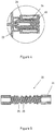
- Coupling means 24 may comprise female "snap-fit" engagement means for receiving corresponding second coupling means 26 of stud 22.
- at least one bridge member 20 may be positioned perpendicularly to a plurality of studs 22 to form skeletal frame 18.
- bridge members 20 may be positioned to extend laterally (horizontally) along interior surfaces 12 i , 14 i of panels 12,14, although reference to the horizontal and vertical are not limiting.
- Side ends may further comprise grooves or recesses 25 ( Figure 5 ) for receiving reinforcing steel, such as re-bar, prior to concrete being poured into cavity 16. It is understood that the reinforcing steel may be utilized to provide further structural integrity to the concrete.
- Figures 3A and 3B show one embodiment of stud member 22 having a first (e.g., upper) end and a second (e.g., lower) end.
- First and second ends of stud 22 may have connection means 22a,22b for slidably engaging other studs 22 positioned adjacent thereto (e.g. above and below) in frame 18.
- first connection means 22a of studs 22 in a first wall section may comprise a female end 22a for slidably receiving the corresponding male end 22b of studs 22 in a second wall structure being positioned above the first wall section.
- studs 22 may be positioned to extend longitudinally (e.g., vertically) along interior surfaces 12 i , 14 i of panels 12,14, although reference to the horizontal and vertical are not limiting. More than one stud 22 may be aligned prior to forming panels 12,14, increasing the length (height) of the panels 12,14 as desired.
- Figures 3A and 3B also show stud member 22 having at least one coupling means 26, said coupling means 26 positioned in spaced longitudinal relation along stud 22, for irreleasably connecting studs 22 to bridge members 20.
- Coupling means 26 may comprise male "snap-fit" engagement means, as shown in Figure 4 , for being received by corresponding coupling means 24 of bridge members 20. It is understood that a plurality of studs 22 may be coupled to at least one bridge member 20 to form skeletal frame 18. Reference to horizontal and vertical are for explanation purposes only.
- first and second panels 12,14 are irreleasably connected to one another via internal frame 18, and that, during installation, adjacent first and second panel 12,14 pairs can be mechanically fastened to one another (eliminating the need to "tie” the panels together), increasing structure stability, but easily disengaged if errors, concept changes or damage to panels 12,14 occur.
- Mechanical engagement between first and second panel 12,14 pairs increases the integrity and strength of the structure, reduces time and expertise required to assemble the structure, and aligns of the panels 12,14 of the overall structure (i.e. pulling adjacent panel pairs together and minimizing skewing between pairs).
- the mechanical connection can also be sufficiently sufficient to prevent any skewing between the wall and the concrete footing (upon which the present ICF panel 10 is installed) by pulling the panels into alignment.
- the panels 12, 14 of the present insulated concrete form panel 10 may be created via manual or automated means, or a combination thereof.
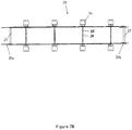
- Figures 8 and 9 depict apparatus 50 for manufacturing panels 12,14 according to embodiments herein. It is understood that apparatus 50 may be used to pre-assemble skeletal frame 18 according to the size of panels 12,14 being manufactured, to apply expandable material to the frame 18 (e.g., allowing the material to mold around, or to, studs 22 of the frame 18), to allow the material to cure thus forming panels 12,14 integral to frame 18 and, once cured, to cut the panels 12,14 to size. Apparatus 50 may be entirely automated.
- panels 12,14 can be molded to pre-assembled frame 18 to form one solid, continuous section of the structure, creating more accurate panel 12,14 tolerances, minimizing on-site adjustment, and reducing worker error (e.g. "gaps" created by hot-wire cutting mechanisms). Molding panels 12,14 directly to the pre-assembled frame 18 enables the present ICF panel 10 to be entirely pre-formed and delivered to the job site for easy installation, saving time, costs and the necessity of having skilled workers.
- the present apparatus and method of making same may result in a substantial reduction in manufacturing and assembly time and costs because the present apparatus may be pre-assembled and pre-molded prior to delivery to the job site, wherein the panels 12,14 pairs need only be mechanically connected together in position (beside each other or one atop the other) at the job site.
- the present insulated concrete form panel 10 may be used to manufacture custom panels, such as corners, angles or windows.
- the present insulated concrete form panel 10 may also be custom designed to be incorporated into or used with pre-existing block or panel ICF systems.
- the width, height and length of the present insulated concrete form panel can be dictated by the size of the structure being built.
- the present ICF panel may be configured such that individual bridge members may have a width (between side ends) corresponding to standard building sizes (i.e. to create a cavity of between approximately two feet and four feet).
- Individual bridge members 20 may further be configured to extend to standard building lengths, or to form panels approximately 4", 6" or 8" long. It is understood, however, that a plurality of bridge members 20 can be aligned end-to-end to create substantially longer panels 12,14.
- the present ICF panel may further be configured such that studs 22 may have a height corresponding to standard building construction (i.e. at least four, eight or twelve feet tall). It is understood that a plurality of stud members 22 may be aligned end to end to create substantially taller panels 12,14.
- the present ICF panel may further be configured to create shaped or non-linear (e.g. curved) panels 12,14.
- Panels 12,14 may also be adapted for use with known or customized "corner" members, as would be appreciated by a person skilled in the art.
- the present ICF panel may be manufactured manually (e.g. assembling frame 18, foaming and cutting the panels 12,14 by hand), automatically by a apparatus 50, or a combination thereof. Where automated, the present system may be entirely continuous, creating a single panel unit that can be easily installed at the construction site.
Landscapes
- Engineering & Computer Science (AREA)
- Architecture (AREA)
- Civil Engineering (AREA)
- Structural Engineering (AREA)
- Physics & Mathematics (AREA)
- Electromagnetism (AREA)
- Mechanical Engineering (AREA)
- Forms Removed On Construction Sites Or Auxiliary Members Thereof (AREA)
- Bridges Or Land Bridges (AREA)
Claims (13)
- Vorgeformtes isoliertes Betonschalungselement (10), umfassend:eine erste und eine zweite Tafel (12 beziehungsweise 14), die aus einem expandierfähigen Polymermaterial hergestellt sind und Außenflächen (12e beziehungsweise 14e) und Innenflächen (12i beziehungsweise 14i) haben und in gegenüberliegender, beabstandeter Beziehung positioniert sind, um einen Hohlraum (16) zwischen den Innenflächen (12i und 14i) zu bilden,wobei das vorgeformte isolierte Betonschalungselement (10) einen inneren Verbinderrahmen (18) hat, der in dem Hohlraum (16) angeordnet ist und eine Vielzahl von Brückengliedern (20) hat, die aufeinander beabstandet und nicht freigebbar mit einer Vielzahl von Abstützungsgliedern (22) des inneren Verbinderrahmens (18) verbunden sind,wobei jedes Brückenglied (20) ein erstes Ende, ein zweites Ende und eine Vielzahl von Seitenenden hat,wobei jedes Seitenende ein gegenüberliegendes erstes Koppelmittel (24) hat, um die Brückenglieder (20) mechanisch an die Abstützungsglieder (22) zu koppeln,wobei jedes Abstützungsglied (22) ein erstes Ende, ein zweites Ende und mindestens ein zweites Koppelmittel (26) hat, wobei jedes erste und zweite Ende Verbindungsmittel (22a, 22b) hat, um benachbarte, Ende an Ende positionierte Abstützungsglieder (22) mechanisch zu verbinden, und wobei das mindestens eine zweite Koppelmittel (26) dem ersten Koppelmittel (24) zum mechanischen Koppeln der Brückenglieder (20) an die Abstützungsglieder (22) entspricht, dadurch gekennzeichnet, dassjedes erste und zweite Ende jedes Brückenglieds (20) Verbindungsmittel (20a, 20b) hat, um benachbarte, Ende an Ende positionierte Brückenglieder (20) mechanisch zu verbinden,und dass die Abstützungsglieder (22) mit dem ersten und dem zweiten Tafelglied (12 und 14) integral sind, so dass das erste und das zweite Tafelglied (12 und 14) um die Abstützungsglieder (22) herum oder an diese geformt sind.
- Vorgeformtes isoliertes Betonschalungselement (10) nach Anspruch 1, wobei sich die Brückenglieder (20) im Wesentlichen senkrecht zu den Abstützungsgliedern (22) erstrecken.
- Vorgeformtes isoliertes Betonschalungselement (10) nach Anspruch 1, wobei die Brückenglieder (20) horizontale Brückenglieder (20) sind und die Abstützungsglieder (22) vertikale Abstützungsglieder (22) sind.
- Vorgeformtes isoliertes Betonschalungselement (10) nach Anspruch 1, wobei das expandierfähige Polymermaterial expandiertes Polystyrol ist.
- Vorgeformtes isoliertes Betonschalungselement (10) nach Anspruch 1, wobei der Verbinderrahmen (18) vormontiert ist, um als eine Form für das Polymermaterial zu dienen.
- Vorgeformtes isoliertes Betonschalungselement (10) nach Anspruch 1, wobei die erste und die zweite Tafel (12 und 14) eine beliebige, vorbestimmte Breite, Höhe und Länge haben.
- Vorgeformtes isoliertes Betonschalungselement (10) nach Anspruch 5, wobei die erste und die zweite Tafel (12 und 14) so geformt sind, dass sie eine Breite von ungefähr 76 - 83 mm (3 - 3 ¼ Zoll) haben.
- Vorgeformtes isoliertes Betonschalungselement (10) nach Anspruch 5, wobei die erste und die zweite Tafel (12 und 14) eine Länge von ungefähr 0,30 - 1,2 m (12 - 48 Zoll) haben.
- Vorgeformtes isoliertes Betonschalungselement (10) nach Anspruch 5, wobei die erste und die zweite Tafel (12 und 14) eine Höhe von mindestens 1,2 m (4 Fuß) haben.
- Vorgeformtes isoliertes Betonschalungselement (10) nach Anspruch 1, wobei das Brückenglied (20) ferner mindestens eine Stabilisierungsstange (27) umfasst.
- Vorgeformtes isoliertes Betonschalungselement (10) nach Anspruch 1, wobei:ein erstes Schalungselement ein benachbartes zweites Schalungselement, das neben, über oder unter dem ersten Schalungselement positioniert ist, mechanisch in Eingriff nehmen kann,das Verbindungsmittel (20a, 20b) jedes Brückenglieds (20) dazu strukturiert ist, benachbarte, Ende an Ende positionierte Brückenglieder (20) mittels einer Reib- oder Presspassung mechanisch zu verbinden, unddas Verbindungsmittel (22a, 22b) jedes Abstützungsglieds (22) dazu strukturiert ist, benachbarte, Ende an Ende positionierte Abstützungsglieder (22) mittels einer Reib- oder Presspassung mechanisch zu verbinden.
- Verfahren zur Herstellung eines isolierten Betonschalungselements (10) nach einem der vorhergehenden Ansprüche, wobei das Element (10) eine erste und eine zweite Tafel (12 und 14) in gegenüberliegender, beabstandeter Beziehung hat, die zwischen sich einen Hohlraum (16) zur Aufnahme von Beton bilden, wobei das Verfahren Folgendes umfasst:a. Bereitstellen von Montagemitteln zum Montieren eines Formrahmens (18), der eine Vielzahl von Brückengliedern (20) hat, die nicht freigebbar mit einer Vielzahl von Abstützungsgliedern (22) verbunden sind, wobei die Brücken- und Abstützungsglieder (22) im Wesentlichen senkrecht zueinander positioniert sind, um den Formrahmen (18) zu bilden, und wobei der Formrahmen (18) in der Form einer Skelettmatrix ist,b. Aufbringen eines expandierfähigen Polymermaterials zum Bilden der ersten und der zweiten Tafel (12 und 14) auf den Formrahmen (18) undc. Gestatten, dass das Polymermaterial erstarrt, wobei jedes Brückenglied (20) ein erstes Ende, ein zweites Ende und eine Vielzahl von Seitenenden hat, wobei jedes erste und zweite Ende Verbindungsmittel (20a, 20b) hat, um benachbarte, Ende an Ende positionierte Brückenglieder (20) mechanisch zu verbinden, und wobei jedes Seitenende ein gegenüberliegendes erstes Koppelmittel (24) hat, um die Brückenglieder (20) mechanisch an die Abstützungsglieder (22) zu koppeln,wobei jedes Abstützungsglied (22) ein erstes Ende, ein zweites Ende und mindestens ein zweites Koppelmittel (26) hat, wobei jedes erste und zweite Ende Verbindungsmittel (22a, 22b) hat, um benachbarte, Ende an Ende positionierte Abstützungsglieder (22) mechanisch zu verbinden, und wobei das mindestens eine zweite Koppelmittel (26) dem ersten Koppelmittel (24) zum mechanischen Koppeln der Brückenglieder (20) an die Abstützungsglieder (22) entspricht.
- Verfahren nach Anspruch 12, wobei das Verfahren manuell, automatisch oder eine Kombination davon ist.
Priority Applications (1)
| Application Number | Priority Date | Filing Date | Title |
|---|---|---|---|
| PL14872280T PL3084095T3 (pl) | 2013-12-17 | 2014-12-16 | Izolowana forma betonowa panelowa i sposób jej wytwarzania |
Applications Claiming Priority (2)
| Application Number | Priority Date | Filing Date | Title |
|---|---|---|---|
| US201361917188P | 2013-12-17 | 2013-12-17 | |
| PCT/CA2014/000904 WO2015089642A1 (en) | 2013-12-17 | 2014-12-16 | Insulated concrete panel form and method of making same |
Publications (3)
| Publication Number | Publication Date |
|---|---|
| EP3084095A1 EP3084095A1 (de) | 2016-10-26 |
| EP3084095A4 EP3084095A4 (de) | 2017-05-03 |
| EP3084095B1 true EP3084095B1 (de) | 2021-02-24 |
Family
ID=53367749
Family Applications (1)
| Application Number | Title | Priority Date | Filing Date |
|---|---|---|---|
| EP14872280.4A Active EP3084095B1 (de) | 2013-12-17 | 2014-12-16 | Isolierte betonplattenform und verfahren zur herstellung davon |
Country Status (5)
| Country | Link |
|---|---|
| US (3) | US10006200B2 (de) |
| EP (1) | EP3084095B1 (de) |
| CA (1) | CA2925625C (de) |
| PL (1) | PL3084095T3 (de) |
| WO (1) | WO2015089642A1 (de) |
Families Citing this family (23)
| Publication number | Priority date | Publication date | Assignee | Title |
|---|---|---|---|---|
| PT2681371E (pt) * | 2011-03-02 | 2015-06-02 | Vst Building Technologies Ag | Processo para a produção contínua de elementos compósitos de painel de cofragem |
| SE538828C2 (sv) * | 2013-08-15 | 2016-12-20 | Incoform Ab | Betongform för bildande av en vägg eller liknande samt ett förfarande för att bilda en sagda vägg eller liknande samt ett stöd |
| EP3084095B1 (de) * | 2013-12-17 | 2021-02-24 | Baader, Benjamin | Isolierte betonplattenform und verfahren zur herstellung davon |
| AU2014410349B2 (en) * | 2014-10-31 | 2020-02-20 | Soletanche Freyssinet | Method for manufacturing concrete construction blocks for a wind-turbine tower and associated system |
| NZ735487A (en) * | 2015-03-27 | 2023-03-31 | Ambe Eng Pty Ltd | System for forming an insulated structural concrete wall |
| US11203866B2 (en) * | 2015-04-20 | 2021-12-21 | Integrated Concrete Forming Ltd. | Insulated concrete form construction method and system |
| US10087642B2 (en) | 2016-01-11 | 2018-10-02 | Robert Montoya | Screen grid insulated concrete form panel system and method for construction and building |
| US10787827B2 (en) | 2016-11-14 | 2020-09-29 | Airlite Plastics Co. | Concrete form with removable sidewall |
| CN106759989B (zh) * | 2016-12-09 | 2019-10-01 | 中民筑友科技投资有限公司 | 保温板及保温板制造方法 |
| TW201928156A (zh) * | 2017-07-17 | 2019-07-16 | 澳商創新建設私人有限公司 | 建築系統,用於建築系統之構件以及使用建築系統之構件的建築方法 |
| CN108277908B (zh) * | 2018-03-27 | 2020-04-17 | 河南高达建筑工程有限公司 | 节能环保型cl墙体工程施工方法 |
| CN108505644B (zh) * | 2018-03-27 | 2019-12-27 | 黄河科技学院 | Cl复合混凝土剪力墙施工方法 |
| CN108442583A (zh) * | 2018-05-31 | 2018-08-24 | 上海言诺建筑材料有限公司 | 连接组件及墙体结构 |
| CA3056094A1 (en) | 2018-09-21 | 2020-03-21 | Cooper E. Stewart | Insulating concrete form apparatus |
| CA3061942A1 (en) * | 2018-11-19 | 2020-05-19 | Bradley J. Crosby | Concrete form with removable sidewall |
| AU2018452355B2 (en) * | 2018-12-12 | 2024-07-04 | Flexbrick, S.L | Architectural enclosure comprised of a structural element and an improved flexible sheet of bricks |
| US12017380B2 (en) | 2019-01-18 | 2024-06-25 | Benjamin Baader | Adjustable apparatus, system and method for constructing insulated concrete forms |
| US11859382B2 (en) | 2019-02-15 | 2024-01-02 | Quickset Limited | Formwork for foundation construction |
| CN111042392A (zh) * | 2019-12-17 | 2020-04-21 | 山东华昊建筑工程配套有限公司 | 一种sdhh型免拆模板发泡混凝土隔墙施工方法 |
| CA3069028A1 (en) * | 2020-01-21 | 2021-07-21 | Benjamin BAADER | An adjustable apparatus, system and method for constructing insulated concrete forms |
| KR102473429B1 (ko) * | 2020-11-11 | 2022-12-05 | 한재희 | 내외측 단열재 지지구 |
| CN115710976A (zh) * | 2022-11-17 | 2023-02-24 | 青岛泰合洋房建设有限公司 | 一种轻钢龙骨结构、板材、装配式建筑及板材制备工艺 |
| KR20250142356A (ko) * | 2023-01-30 | 2025-09-30 | 시트라 그룹 에이지 | 구조물 및 시공 방법 |
Family Cites Families (67)
| Publication number | Priority date | Publication date | Assignee | Title |
|---|---|---|---|---|
| US2365563A (en) * | 1944-12-19 | Form tie assembly for concrete | ||
| US839819A (en) * | 1906-05-18 | 1907-01-01 | William E De Lhorbe | Form for plastic building-walls. |
| US1421956A (en) * | 1920-12-22 | 1922-07-04 | Herman J Kestler | Collapsible mold for concrete structures |
| US1852049A (en) * | 1931-04-14 | 1932-04-05 | Russell C Graef | Building construction |
| US1991256A (en) * | 1933-09-06 | 1935-02-12 | Muntz Eric Percival | Spreading device for concrete form work |
| US2739364A (en) * | 1952-11-14 | 1956-03-27 | Orlo W Clemans | Building wall structure |
| US3751867A (en) * | 1971-12-03 | 1973-08-14 | Raymond Lee Organization Inc | Panel to form composite concrete-reinforced wall |
| DE2414951C3 (de) * | 1974-03-28 | 1979-10-25 | Karl 5231 Weyerbusch Liedgens | Zusammenklappbares Schalungselement für Mantelbetonwände |
| US3995825A (en) * | 1975-08-01 | 1976-12-07 | Ward Edward B | Form tie for concrete form structures |
| FR2552472B2 (fr) | 1983-02-08 | 1985-11-08 | Ott Renaud | Systeme constructif utilisant des coffrages perdus notamment isolants et armes |
| US4765109A (en) * | 1987-09-25 | 1988-08-23 | Boeshart Patrick E | Adjustable tie |
| US4972646A (en) * | 1988-03-14 | 1990-11-27 | Foam Form Systems, Inc. | Concrete forming system |
| US4889310A (en) * | 1988-05-26 | 1989-12-26 | Boeshart Patrick E | Concrete forming system |
| US4936540A (en) * | 1989-02-13 | 1990-06-26 | Boeshart Patrick E | Tie for concrete forms |
| US4938449A (en) * | 1989-02-13 | 1990-07-03 | Boeshart Patrick E | Tie for concrete forms |
| CA2032640C (en) * | 1990-12-19 | 1994-07-26 | Claude Chagnon | Prefabricated formwork |
| CA2111801A1 (en) | 1993-12-17 | 1995-06-18 | Roland H. Liebregts | Insulated construction form element and reinforcement therefor, and wall construction |
| US5459971A (en) * | 1994-03-04 | 1995-10-24 | Sparkman; Alan | Connecting member for concrete form |
| US5431368A (en) * | 1994-03-31 | 1995-07-11 | Wilde; Richard L. | Tie for concrete wall forms |
| US5497592A (en) * | 1994-05-19 | 1996-03-12 | Boeshart; Patrick E. | Quick release tie |
| US5657600A (en) * | 1994-06-20 | 1997-08-19 | Aab Building Systems Inc. | Web member for concrete form walls |
| FR2738856B1 (fr) | 1995-09-19 | 1997-10-31 | Viannay Quideau Marine | Dispositif d'assemblage de banches en u verticaux egaux consecutifs utilises en coffrages perdus legers |
| US5735093A (en) * | 1996-02-13 | 1998-04-07 | Grutsch; George A. | Concrete formwork with backing plates |
| CA2182055C (en) * | 1996-07-25 | 1999-05-11 | Julien Martineau | Concrete form system, ties therefor, and method of using the system and ties |
| CA2219414A1 (en) * | 1996-11-26 | 1998-05-26 | Allen Meendering | Tie for forms for poured concrete |
| US6978581B1 (en) * | 1997-02-04 | 2005-12-27 | Pentstar Corporation | Composite building block with connective structure |
| CA2209251C (en) * | 1997-07-04 | 2001-10-02 | Frank B. Bentley | Form system |
| US6079176A (en) * | 1997-09-29 | 2000-06-27 | Westra; Albert P. | Insulated concrete wall |
| US5890337A (en) * | 1997-10-14 | 1999-04-06 | Boeshart; Patrick E. | Double tie |
| US6609340B2 (en) * | 1998-01-16 | 2003-08-26 | Eco-Block, Llc | Concrete structures and methods of forming the same using extenders |
| US5992114A (en) * | 1998-04-13 | 1999-11-30 | Zelinsky; Ronald Dean | Apparatus for forming a poured concrete wall |
| US6336301B1 (en) * | 1998-11-05 | 2002-01-08 | James D. Moore, Jr. | Concrete form system ledge assembly and method |
| US6314694B1 (en) * | 1998-12-17 | 2001-11-13 | Arxx Building Products Inc. | One-sided insulated formwork |
| CA2256091A1 (en) | 1998-12-23 | 2000-06-23 | Jean-Louis Beliveau | Concrete wall form and connectors therefor |
| US6279285B1 (en) * | 1999-01-18 | 2001-08-28 | K-Wall Poured Walls, Inc. | Insulated concrete wall system |
| US6668503B2 (en) * | 1999-04-16 | 2003-12-30 | Polyform A.G.P. Inc. | Concrete wall form and connectors therefor |
| US6318040B1 (en) * | 1999-10-25 | 2001-11-20 | James D. Moore, Jr. | Concrete form system and method |
| US6256962B1 (en) * | 2000-01-12 | 2001-07-10 | Patrick E. Boeshart | Tie for reusable form panels |
| US6647686B2 (en) * | 2001-03-09 | 2003-11-18 | Daniel D. Dunn | System for constructing insulated concrete structures |
| US6886303B2 (en) * | 2001-08-20 | 2005-05-03 | Donald L. Schmidt | Form bracing tie bracket for modular insulating concrete form system and form using the same |
| US6898912B2 (en) * | 2002-04-15 | 2005-05-31 | Leonid G. Bravinski | System and method for the reinforcement of concrete |
| US6948289B2 (en) * | 2002-09-24 | 2005-09-27 | Leonid Bravinski | Method and means for prefabrication of 3D construction forms |
| US6951329B2 (en) * | 2003-01-07 | 2005-10-04 | Symons Corporation | Concrete wall form with flexible tie system |
| US6854229B2 (en) * | 2003-05-29 | 2005-02-15 | H.K. Marketing Llc | Form tie sleeves for composite action insulated concrete sandwich walls |
| HRP20040578B1 (hr) * | 2004-06-21 | 2012-11-30 | Pjer-Miše Veličković | Varijabilne spone za povezivanje oplate od izo-ploäśa visoke nosivosti, ispune i izo-ispune visoke nosivosti za postavljanje a/b ploäśe |
| US8997420B2 (en) * | 2004-11-29 | 2015-04-07 | Victor Amend | Reinforced insulated forms for constructing concrete walls and floors |
| EP1819887B1 (de) * | 2004-12-07 | 2012-07-11 | Buildblock Building Systems, L.L.C. | Isolierender betonblock |
| CA2496704A1 (fr) * | 2005-02-07 | 2006-08-07 | Serge Meilleur | Module de coffrage metallique prefabrique pour beton |
| US20060248832A1 (en) * | 2005-05-06 | 2006-11-09 | Shidler David C | Concrete wall form tie |
| ITTO20050393A1 (it) * | 2005-06-09 | 2006-12-10 | Pontarolo Engineering Spa | Cassero a perdere per murature isolate in cemento armato. |
| US20060277855A1 (en) * | 2005-06-13 | 2006-12-14 | Westra Gregory A | Method and apparatus for insulating a concrete wall |
| US7757448B2 (en) * | 2005-10-17 | 2010-07-20 | Zhu Qinjiang | Assemblage concrete forms and method for manufacturing thereof |
| NO333274B1 (no) * | 2005-11-03 | 2013-04-29 | John A Simonsen | Avstandsstag for sammenfoyning av en stopeforskalings motstaende sideseksjoner. |
| US20080083867A1 (en) * | 2006-10-10 | 2008-04-10 | Durand Forms Incorporated | Connecting tie for metal concrete pouring forms |
| US20090013629A1 (en) * | 2007-07-09 | 2009-01-15 | Boeshart Patrick E | Method and Apparatus for Using Foam Panels As Forms For Making Concrete Walls |
| CA2597832A1 (en) | 2007-08-28 | 2009-02-28 | Green Built Manufacturing Inc. | Building elements formed using straps |
| US20090218474A1 (en) * | 2007-10-09 | 2009-09-03 | Accelerated Building Technologies Llc | Single faced insulated concrete form |
| US8191853B2 (en) * | 2008-01-04 | 2012-06-05 | Composite Technologies Corporation | Concrete form holding a partial sheet of insulation at a preselected position therein |
| US8632332B2 (en) * | 2009-09-10 | 2014-01-21 | Tf Forming Systems, Inc. | Vertical concrete form with removable forming panels |
| US8555583B2 (en) * | 2010-04-02 | 2013-10-15 | Romeo Ilarian Ciuperca | Reinforced insulated concrete form |
| US20130312350A1 (en) * | 2010-11-12 | 2013-11-28 | Kenneth Robert Kreizinger | Plastic Stay-In-Place Concrete Forming System |
| US8555584B2 (en) * | 2011-09-28 | 2013-10-15 | Romeo Ilarian Ciuperca | Precast concrete structures, precast tilt-up concrete structures and methods of making same |
| US8756890B2 (en) * | 2011-09-28 | 2014-06-24 | Romeo Ilarian Ciuperca | Insulated concrete form and method of using same |
| US8887465B2 (en) * | 2012-01-13 | 2014-11-18 | Airlite Plastics Co. | Apparatus and method for construction of structures utilizing insulated concrete forms |
| US8635826B2 (en) * | 2012-04-10 | 2014-01-28 | Reward Wall Systems, Inc. | Insulation insert panel for use with insulating concrete form (ICF) systems |
| CA2817332C (en) * | 2012-06-06 | 2015-07-21 | William R. Hilliard, Sr. | Interlocking web for insulated concrete forms |
| EP3084095B1 (de) * | 2013-12-17 | 2021-02-24 | Baader, Benjamin | Isolierte betonplattenform und verfahren zur herstellung davon |
-
2014
- 2014-12-16 EP EP14872280.4A patent/EP3084095B1/de active Active
- 2014-12-16 PL PL14872280T patent/PL3084095T3/pl unknown
- 2014-12-16 CA CA2925625A patent/CA2925625C/en active Active
- 2014-12-16 WO PCT/CA2014/000904 patent/WO2015089642A1/en not_active Ceased
- 2014-12-16 US US15/030,944 patent/US10006200B2/en active Active
- 2014-12-17 US US14/573,395 patent/US20150167295A1/en not_active Abandoned
-
2018
- 2018-06-26 US US16/019,303 patent/US20190093355A1/en not_active Abandoned
Non-Patent Citations (1)
| Title |
|---|
| None * |
Also Published As
| Publication number | Publication date |
|---|---|
| WO2015089642A1 (en) | 2015-06-25 |
| CA2925625A1 (en) | 2015-06-25 |
| EP3084095A4 (de) | 2017-05-03 |
| PL3084095T3 (pl) | 2021-10-25 |
| US20150167295A1 (en) | 2015-06-18 |
| EP3084095A1 (de) | 2016-10-26 |
| US20190093355A1 (en) | 2019-03-28 |
| US20160281361A1 (en) | 2016-09-29 |
| CA2925625C (en) | 2022-06-14 |
| US10006200B2 (en) | 2018-06-26 |
Similar Documents
| Publication | Publication Date | Title |
|---|---|---|
| US10006200B2 (en) | Insulated concrete panel form and method of making same | |
| US8443560B2 (en) | Concrete form block and form block structure | |
| US8887465B2 (en) | Apparatus and method for construction of structures utilizing insulated concrete forms | |
| EP1846625B1 (de) | Betonwandschalungsmodul | |
| AU2015278245B2 (en) | Formwork | |
| US10753109B2 (en) | Concrete form tie, and concrete formwork comprising same | |
| KR200481707Y1 (ko) | 거푸집 겸용 외장벽판 | |
| US20150089894A1 (en) | Stay-in-place concrete form | |
| US8827235B1 (en) | Concrete form for building foundation construction with form insert creating recessed sections | |
| CA2953386C (en) | Prefabricated module for casting a concrete wall | |
| CN112262245A (zh) | 空隙形成器 | |
| CN109736478B (zh) | L型、t型混凝土剪力墙结构组合型预制边缘构件 | |
| US8800218B2 (en) | Insulating construction panels, systems and methods | |
| WO2011138573A2 (en) | A construction system | |
| US10132077B2 (en) | Fast construction of energy-efficient buildings | |
| CA3014571C (en) | Concrete form tie, and concrete formwork comprising same | |
| KR20140111432A (ko) | 거푸집 없이 시공되는 패널 일체형 콘크리트 벽체 및 이를 포함하는 건축 구조물 | |
| CN210067118U (zh) | L型、t型混凝土剪力墙结构组合型预制边缘构件 | |
| KR102933472B1 (ko) | 콘크리트 단열블록을 이용한 신축건물 시공 방법 | |
| WO2013020228A1 (en) | Prefabricated wall module and method of fabrication | |
| JP3689168B2 (ja) | 型枠兼用断熱基礎ブロック | |
| HK40131825A (zh) | 用於建筑物和土木工程的结构系统以及建造方法 | |
| LT6429B (lt) | Savaime susicentruojantys , konstrukcinę apkrovą laikantys statybos elementai ir juos naudojantis nešančiųjų konstrukcijų būdas , sutvirtinant konstrukcinėmis grotelėmis, nenaudojant klijuojančio sluoksnio | |
| JP2001200606A (ja) | 型枠および型枠工法 |
Legal Events
| Date | Code | Title | Description |
|---|---|---|---|
| PUAI | Public reference made under article 153(3) epc to a published international application that has entered the european phase |
Free format text: ORIGINAL CODE: 0009012 |
|
| 17P | Request for examination filed |
Effective date: 20160610 |
|
| AK | Designated contracting states |
Kind code of ref document: A1 Designated state(s): AL AT BE BG CH CY CZ DE DK EE ES FI FR GB GR HR HU IE IS IT LI LT LU LV MC MK MT NL NO PL PT RO RS SE SI SK SM TR |
|
| AX | Request for extension of the european patent |
Extension state: BA ME |
|
| DAX | Request for extension of the european patent (deleted) | ||
| A4 | Supplementary search report drawn up and despatched |
Effective date: 20170405 |
|
| RIC1 | Information provided on ipc code assigned before grant |
Ipc: B28B 23/00 20060101ALI20170330BHEP Ipc: B28B 7/22 20060101ALI20170330BHEP Ipc: E04B 2/86 20060101AFI20170330BHEP |
|
| STAA | Information on the status of an ep patent application or granted ep patent |
Free format text: STATUS: REQUEST FOR EXAMINATION WAS MADE |
|
| STAA | Information on the status of an ep patent application or granted ep patent |
Free format text: STATUS: EXAMINATION IS IN PROGRESS |
|
| 17Q | First examination report despatched |
Effective date: 20200115 |
|
| GRAP | Despatch of communication of intention to grant a patent |
Free format text: ORIGINAL CODE: EPIDOSNIGR1 |
|
| STAA | Information on the status of an ep patent application or granted ep patent |
Free format text: STATUS: GRANT OF PATENT IS INTENDED |
|
| RIC1 | Information provided on ipc code assigned before grant |
Ipc: B29L 31/00 20060101ALN20200615BHEP Ipc: B29C 44/12 20060101ALI20200615BHEP Ipc: E04B 2/86 20060101AFI20200615BHEP Ipc: B29K 25/00 20060101ALN20200615BHEP Ipc: B29K 105/04 20060101ALN20200615BHEP |
|
| INTG | Intention to grant announced |
Effective date: 20200703 |
|
| RIC1 | Information provided on ipc code assigned before grant |
Ipc: E04B 2/86 20060101AFI20200619BHEP Ipc: B29L 31/00 20060101ALN20200619BHEP Ipc: B29C 44/12 20060101ALI20200619BHEP Ipc: B29K 25/00 20060101ALN20200619BHEP Ipc: B29K 105/04 20060101ALN20200619BHEP |
|
| GRAS | Grant fee paid |
Free format text: ORIGINAL CODE: EPIDOSNIGR3 |
|
| GRAA | (expected) grant |
Free format text: ORIGINAL CODE: 0009210 |
|
| STAA | Information on the status of an ep patent application or granted ep patent |
Free format text: STATUS: THE PATENT HAS BEEN GRANTED |
|
| AK | Designated contracting states |
Kind code of ref document: B1 Designated state(s): AL AT BE BG CH CY CZ DE DK EE ES FI FR GB GR HR HU IE IS IT LI LT LU LV MC MK MT NL NO PL PT RO RS SE SI SK SM TR |
|
| REG | Reference to a national code |
Ref country code: GB Ref legal event code: FG4D |
|
| REG | Reference to a national code |
Ref country code: CH Ref legal event code: EP |
|
| REG | Reference to a national code |
Ref country code: DE Ref legal event code: R096 Ref document number: 602014075234 Country of ref document: DE |
|
| REG | Reference to a national code |
Ref country code: AT Ref legal event code: REF Ref document number: 1364603 Country of ref document: AT Kind code of ref document: T Effective date: 20210315 |
|
| REG | Reference to a national code |
Ref country code: IE Ref legal event code: FG4D |
|
| REG | Reference to a national code |
Ref country code: LT Ref legal event code: MG9D |
|
| REG | Reference to a national code |
Ref country code: NL Ref legal event code: MP Effective date: 20210224 |
|
| PG25 | Lapsed in a contracting state [announced via postgrant information from national office to epo] |
Ref country code: NO Free format text: LAPSE BECAUSE OF FAILURE TO SUBMIT A TRANSLATION OF THE DESCRIPTION OR TO PAY THE FEE WITHIN THE PRESCRIBED TIME-LIMIT Effective date: 20210524 Ref country code: BG Free format text: LAPSE BECAUSE OF FAILURE TO SUBMIT A TRANSLATION OF THE DESCRIPTION OR TO PAY THE FEE WITHIN THE PRESCRIBED TIME-LIMIT Effective date: 20210524 Ref country code: LT Free format text: LAPSE BECAUSE OF FAILURE TO SUBMIT A TRANSLATION OF THE DESCRIPTION OR TO PAY THE FEE WITHIN THE PRESCRIBED TIME-LIMIT Effective date: 20210224 Ref country code: PT Free format text: LAPSE BECAUSE OF FAILURE TO SUBMIT A TRANSLATION OF THE DESCRIPTION OR TO PAY THE FEE WITHIN THE PRESCRIBED TIME-LIMIT Effective date: 20210624 Ref country code: FI Free format text: LAPSE BECAUSE OF FAILURE TO SUBMIT A TRANSLATION OF THE DESCRIPTION OR TO PAY THE FEE WITHIN THE PRESCRIBED TIME-LIMIT Effective date: 20210224 Ref country code: GR Free format text: LAPSE BECAUSE OF FAILURE TO SUBMIT A TRANSLATION OF THE DESCRIPTION OR TO PAY THE FEE WITHIN THE PRESCRIBED TIME-LIMIT Effective date: 20210525 Ref country code: HR Free format text: LAPSE BECAUSE OF FAILURE TO SUBMIT A TRANSLATION OF THE DESCRIPTION OR TO PAY THE FEE WITHIN THE PRESCRIBED TIME-LIMIT Effective date: 20210224 |
|
| PG25 | Lapsed in a contracting state [announced via postgrant information from national office to epo] |
Ref country code: SE Free format text: LAPSE BECAUSE OF FAILURE TO SUBMIT A TRANSLATION OF THE DESCRIPTION OR TO PAY THE FEE WITHIN THE PRESCRIBED TIME-LIMIT Effective date: 20210224 Ref country code: RS Free format text: LAPSE BECAUSE OF FAILURE TO SUBMIT A TRANSLATION OF THE DESCRIPTION OR TO PAY THE FEE WITHIN THE PRESCRIBED TIME-LIMIT Effective date: 20210224 Ref country code: NL Free format text: LAPSE BECAUSE OF FAILURE TO SUBMIT A TRANSLATION OF THE DESCRIPTION OR TO PAY THE FEE WITHIN THE PRESCRIBED TIME-LIMIT Effective date: 20210224 Ref country code: LV Free format text: LAPSE BECAUSE OF FAILURE TO SUBMIT A TRANSLATION OF THE DESCRIPTION OR TO PAY THE FEE WITHIN THE PRESCRIBED TIME-LIMIT Effective date: 20210224 |
|
| PG25 | Lapsed in a contracting state [announced via postgrant information from national office to epo] |
Ref country code: IS Free format text: LAPSE BECAUSE OF FAILURE TO SUBMIT A TRANSLATION OF THE DESCRIPTION OR TO PAY THE FEE WITHIN THE PRESCRIBED TIME-LIMIT Effective date: 20210624 |
|
| PG25 | Lapsed in a contracting state [announced via postgrant information from national office to epo] |
Ref country code: EE Free format text: LAPSE BECAUSE OF FAILURE TO SUBMIT A TRANSLATION OF THE DESCRIPTION OR TO PAY THE FEE WITHIN THE PRESCRIBED TIME-LIMIT Effective date: 20210224 Ref country code: CZ Free format text: LAPSE BECAUSE OF FAILURE TO SUBMIT A TRANSLATION OF THE DESCRIPTION OR TO PAY THE FEE WITHIN THE PRESCRIBED TIME-LIMIT Effective date: 20210224 Ref country code: SM Free format text: LAPSE BECAUSE OF FAILURE TO SUBMIT A TRANSLATION OF THE DESCRIPTION OR TO PAY THE FEE WITHIN THE PRESCRIBED TIME-LIMIT Effective date: 20210224 |
|
| REG | Reference to a national code |
Ref country code: AT Ref legal event code: UEP Ref document number: 1364603 Country of ref document: AT Kind code of ref document: T Effective date: 20210224 |
|
| REG | Reference to a national code |
Ref country code: DE Ref legal event code: R097 Ref document number: 602014075234 Country of ref document: DE |
|
| PG25 | Lapsed in a contracting state [announced via postgrant information from national office to epo] |
Ref country code: RO Free format text: LAPSE BECAUSE OF FAILURE TO SUBMIT A TRANSLATION OF THE DESCRIPTION OR TO PAY THE FEE WITHIN THE PRESCRIBED TIME-LIMIT Effective date: 20210224 Ref country code: SK Free format text: LAPSE BECAUSE OF FAILURE TO SUBMIT A TRANSLATION OF THE DESCRIPTION OR TO PAY THE FEE WITHIN THE PRESCRIBED TIME-LIMIT Effective date: 20210224 Ref country code: ES Free format text: LAPSE BECAUSE OF FAILURE TO SUBMIT A TRANSLATION OF THE DESCRIPTION OR TO PAY THE FEE WITHIN THE PRESCRIBED TIME-LIMIT Effective date: 20210224 Ref country code: DK Free format text: LAPSE BECAUSE OF FAILURE TO SUBMIT A TRANSLATION OF THE DESCRIPTION OR TO PAY THE FEE WITHIN THE PRESCRIBED TIME-LIMIT Effective date: 20210224 |
|
| PLBE | No opposition filed within time limit |
Free format text: ORIGINAL CODE: 0009261 |
|
| STAA | Information on the status of an ep patent application or granted ep patent |
Free format text: STATUS: NO OPPOSITION FILED WITHIN TIME LIMIT |
|
| PG25 | Lapsed in a contracting state [announced via postgrant information from national office to epo] |
Ref country code: AL Free format text: LAPSE BECAUSE OF FAILURE TO SUBMIT A TRANSLATION OF THE DESCRIPTION OR TO PAY THE FEE WITHIN THE PRESCRIBED TIME-LIMIT Effective date: 20210224 |
|
| 26N | No opposition filed |
Effective date: 20211125 |
|
| PG25 | Lapsed in a contracting state [announced via postgrant information from national office to epo] |
Ref country code: SI Free format text: LAPSE BECAUSE OF FAILURE TO SUBMIT A TRANSLATION OF THE DESCRIPTION OR TO PAY THE FEE WITHIN THE PRESCRIBED TIME-LIMIT Effective date: 20210224 |
|
| PG25 | Lapsed in a contracting state [announced via postgrant information from national office to epo] |
Ref country code: IS Free format text: LAPSE BECAUSE OF FAILURE TO SUBMIT A TRANSLATION OF THE DESCRIPTION OR TO PAY THE FEE WITHIN THE PRESCRIBED TIME-LIMIT Effective date: 20210624 |
|
| PG25 | Lapsed in a contracting state [announced via postgrant information from national office to epo] |
Ref country code: MC Free format text: LAPSE BECAUSE OF FAILURE TO SUBMIT A TRANSLATION OF THE DESCRIPTION OR TO PAY THE FEE WITHIN THE PRESCRIBED TIME-LIMIT Effective date: 20210224 |
|
| REG | Reference to a national code |
Ref country code: CH Ref legal event code: PL |
|
| GBPC | Gb: european patent ceased through non-payment of renewal fee |
Effective date: 20211216 |
|
| REG | Reference to a national code |
Ref country code: BE Ref legal event code: MM Effective date: 20211231 |
|
| PG25 | Lapsed in a contracting state [announced via postgrant information from national office to epo] |
Ref country code: LU Free format text: LAPSE BECAUSE OF NON-PAYMENT OF DUE FEES Effective date: 20211216 Ref country code: IE Free format text: LAPSE BECAUSE OF NON-PAYMENT OF DUE FEES Effective date: 20211216 Ref country code: GB Free format text: LAPSE BECAUSE OF NON-PAYMENT OF DUE FEES Effective date: 20211216 |
|
| PG25 | Lapsed in a contracting state [announced via postgrant information from national office to epo] |
Ref country code: FR Free format text: LAPSE BECAUSE OF NON-PAYMENT OF DUE FEES Effective date: 20211231 Ref country code: BE Free format text: LAPSE BECAUSE OF NON-PAYMENT OF DUE FEES Effective date: 20211231 |
|
| PG25 | Lapsed in a contracting state [announced via postgrant information from national office to epo] |
Ref country code: LI Free format text: LAPSE BECAUSE OF NON-PAYMENT OF DUE FEES Effective date: 20211231 Ref country code: CH Free format text: LAPSE BECAUSE OF NON-PAYMENT OF DUE FEES Effective date: 20211231 |
|
| PG25 | Lapsed in a contracting state [announced via postgrant information from national office to epo] |
Ref country code: HU Free format text: LAPSE BECAUSE OF FAILURE TO SUBMIT A TRANSLATION OF THE DESCRIPTION OR TO PAY THE FEE WITHIN THE PRESCRIBED TIME-LIMIT; INVALID AB INITIO Effective date: 20141216 |
|
| PG25 | Lapsed in a contracting state [announced via postgrant information from national office to epo] |
Ref country code: CY Free format text: LAPSE BECAUSE OF FAILURE TO SUBMIT A TRANSLATION OF THE DESCRIPTION OR TO PAY THE FEE WITHIN THE PRESCRIBED TIME-LIMIT Effective date: 20210224 |
|
| PG25 | Lapsed in a contracting state [announced via postgrant information from national office to epo] |
Ref country code: MK Free format text: LAPSE BECAUSE OF FAILURE TO SUBMIT A TRANSLATION OF THE DESCRIPTION OR TO PAY THE FEE WITHIN THE PRESCRIBED TIME-LIMIT Effective date: 20210224 |
|
| PG25 | Lapsed in a contracting state [announced via postgrant information from national office to epo] |
Ref country code: MT Free format text: LAPSE BECAUSE OF FAILURE TO SUBMIT A TRANSLATION OF THE DESCRIPTION OR TO PAY THE FEE WITHIN THE PRESCRIBED TIME-LIMIT Effective date: 20210224 |
|
| PGFP | Annual fee paid to national office [announced via postgrant information from national office to epo] |
Ref country code: AT Payment date: 20251222 Year of fee payment: 12 |
|
| PGFP | Annual fee paid to national office [announced via postgrant information from national office to epo] |
Ref country code: TR Payment date: 20251216 Year of fee payment: 12 |
|
| PGFP | Annual fee paid to national office [announced via postgrant information from national office to epo] |
Ref country code: PL Payment date: 20251216 Year of fee payment: 12 |
|
| PGFP | Annual fee paid to national office [announced via postgrant information from national office to epo] |
Ref country code: DE Payment date: 20251222 Year of fee payment: 12 |
|
| PGFP | Annual fee paid to national office [announced via postgrant information from national office to epo] |
Ref country code: IT Payment date: 20251222 Year of fee payment: 12 |