EP3084103B1 - Structure de protection pour partitions de panneaux - Google Patents
Structure de protection pour partitions de panneaux Download PDFInfo
- Publication number
- EP3084103B1 EP3084103B1 EP14825327.1A EP14825327A EP3084103B1 EP 3084103 B1 EP3084103 B1 EP 3084103B1 EP 14825327 A EP14825327 A EP 14825327A EP 3084103 B1 EP3084103 B1 EP 3084103B1
- Authority
- EP
- European Patent Office
- Prior art keywords
- board
- protective structure
- seismic
- support element
- partition
- Prior art date
- Legal status (The legal status is an assumption and is not a legal conclusion. Google has not performed a legal analysis and makes no representation as to the accuracy of the status listed.)
- Active
Links
Images




Classifications
-
- E—FIXED CONSTRUCTIONS
- E04—BUILDING
- E04H—BUILDINGS OR LIKE STRUCTURES FOR PARTICULAR PURPOSES; SWIMMING OR SPLASH BATHS OR POOLS; MASTS; FENCING; TENTS OR CANOPIES, IN GENERAL
- E04H9/00—Buildings, groups of buildings or shelters adapted to withstand or provide protection against abnormal external influences, e.g. war-like action, earthquake or extreme climate
- E04H9/02—Buildings, groups of buildings or shelters adapted to withstand or provide protection against abnormal external influences, e.g. war-like action, earthquake or extreme climate withstanding earthquake or sinking of ground
- E04H9/021—Bearing, supporting or connecting constructions specially adapted for such buildings
-
- E—FIXED CONSTRUCTIONS
- E04—BUILDING
- E04B—GENERAL BUILDING CONSTRUCTIONS; WALLS, e.g. PARTITIONS; ROOFS; FLOORS; CEILINGS; INSULATION OR OTHER PROTECTION OF BUILDINGS
- E04B1/00—Constructions in general; Structures which are not restricted either to walls, e.g. partitions, or floors or ceilings or roofs
- E04B1/62—Insulation or other protection; Elements or use of specified material therefor
- E04B1/92—Protection against other undesired influences or dangers
- E04B1/98—Protection against other undesired influences or dangers against vibrations or shocks; against mechanical destruction, e.g. by air-raids
-
- E—FIXED CONSTRUCTIONS
- E04—BUILDING
- E04B—GENERAL BUILDING CONSTRUCTIONS; WALLS, e.g. PARTITIONS; ROOFS; FLOORS; CEILINGS; INSULATION OR OTHER PROTECTION OF BUILDINGS
- E04B2/00—Walls, e.g. partitions, for buildings; Wall construction with regard to insulation; Connections specially adapted to walls
- E04B2/72—Non-load-bearing walls of elements of relatively thin form with respect to the thickness of the wall
- E04B2/721—Non-load-bearing walls of elements of relatively thin form with respect to the thickness of the wall connections specially adapted therefor
-
- E—FIXED CONSTRUCTIONS
- E04—BUILDING
- E04B—GENERAL BUILDING CONSTRUCTIONS; WALLS, e.g. PARTITIONS; ROOFS; FLOORS; CEILINGS; INSULATION OR OTHER PROTECTION OF BUILDINGS
- E04B2/00—Walls, e.g. partitions, for buildings; Wall construction with regard to insulation; Connections specially adapted to walls
- E04B2/74—Removable non-load-bearing partitions; Partitions with a free upper edge
- E04B2/7407—Removable non-load-bearing partitions; Partitions with a free upper edge assembled using frames with infill panels or coverings only; made-up of panels and a support structure incorporating posts
- E04B2/7453—Removable non-load-bearing partitions; Partitions with a free upper edge assembled using frames with infill panels or coverings only; made-up of panels and a support structure incorporating posts with panels and support posts, extending from floor to ceiling
- E04B2/7457—Removable non-load-bearing partitions; Partitions with a free upper edge assembled using frames with infill panels or coverings only; made-up of panels and a support structure incorporating posts with panels and support posts, extending from floor to ceiling with wallboards attached to the outer faces of the posts, parallel to the partition
-
- E—FIXED CONSTRUCTIONS
- E04—BUILDING
- E04B—GENERAL BUILDING CONSTRUCTIONS; WALLS, e.g. PARTITIONS; ROOFS; FLOORS; CEILINGS; INSULATION OR OTHER PROTECTION OF BUILDINGS
- E04B2/00—Walls, e.g. partitions, for buildings; Wall construction with regard to insulation; Connections specially adapted to walls
- E04B2/74—Removable non-load-bearing partitions; Partitions with a free upper edge
- E04B2/82—Removable non-load-bearing partitions; Partitions with a free upper edge characterised by the manner in which edges are connected to the building; Means therefor; Special details of easily-removable partitions as far as related to the connection with other parts of the building
- E04B2/828—Connections between partitions and structural walls
Definitions
- the present invention relates to the field of board partitions. More specifically it relates to a protective structure for limiting damage to board material partitions, e.g. plasterboard partitions, caused by earthquakes.
- board material partitions e.g. plasterboard partitions
- Inner walls typically get damaged during earthquakes.
- Inner walls typically may be constructed as plasterboard partition walls, which are built using a sub-structure made of e.g. wood or metal studs, on which plasterboards are mounted.
- these board partition walls can collapse or break due to forces on the plasterboard partition walls.
- movements of the building during an earthquake typically may induce deformation of the sub-structure of the partition wall, resulting in damage to both the plasterboard wall as well as to the underlying sub-structure.
- Japanese patent application JP06001520 describes one solution for reducing damage to a partition by adjusting the connection of the partition with other walls that induce stress on the partition during earthquakes.
- the connection is made using a linking device having an accordion-like structure allowing relative movement between the inner walls.
- the linking device may be an attachment/detachment device that links the walls but that can be released when a predetermined force or larger is applied, e.g. during an earthquake.
- the linking device might for example be a door that is kept close using magnets and that opens when a too large force is applied.
- British patent application GB-A-2265169 describes a shock absorbing partition wall having wall panels separated by studs with side members, which are resiliently mounted relative to each other to absorb shocks.
- a seismic protective structure comprises at least one board and support elements for positioning the board adjacent a neighboring wall and linking the board to the remainder of the board partition wall.
- the seismic protective structure is adapted for, when a given level of seismic stress is appearing, intentionally causing damage of the at least one board thereby releasing pressure from the remainder of the board partition.
- the present invention relates to a seismic protective structure for forming part of a board partition and for limiting damage to the board partition when a given level of seismic stress is appearing, the seismic protective structure comprising
- the seismic protective structure may be adapted for, when a given level of seismic stress is appearing, intentionally causing damage of at least a first board at one side of the board partition, and of at least a second board at the other, opposite side of the board partition, thereby releasing stress from the remainder of the board partition, more particular releasing stress from the remainder of the boards at both sides of the board partition.
- the acute angle between the axes of the first and second support element be less than 20°, typically less than 15°, such as less than 10°.
- the first and second support element may be substantially parallel. Substantially parallel is to be understood as will the acute angle between the axes of these support elements be less than 5°.
- the board may be an edge board, i.e. a board positioned at the edge of the board partition, but the invention is not limited thereto and can also relate to a system and method for breaking a board at another position in the partition board.
- the board will damage, e.g. break, at smaller levels of stress, e.g. at smaller displacement caused by seismic activity, than the remainder part of the partition structure will do thus removing pressure from the rest of the board partition thereby avoiding damage over the complete board partition and only introducing damage in the seismic protective structure.
- the board breaks if the energy build up in the board exceeds a certain limit or if the displacement of the track with regard to the first vertical support element exceeds a certain distance. This prevents pressure to build up in the remainder part of the partition structure causing it to break. In this way, it can be avoided that boards such as gypsum boards or support elements in the remainder part cause damage to the environment due to failure.
- the seismic protective structure may comprise a stress inducing element for introducing, when a given level of seismic stress is appearing on the board partition, additional stress on the at least one board and/or the first, optionally substantially vertical, support element for causing the seismic protective structure to damage before the rest of the board partition breaks.
- the stress inducing means induces a force on the protective structure which causes the protective structure to break. It is an advantage of embodiments of the current invention that during an earthquake the wedge induces a force on the first support element causing the first support element to break before parts of the rest of the board partition break.
- the additional stress may be introduced directly on the board, on the first support element, or indirectly on the board via deformation or breaking of the first support element.
- the stress inducing element may comprise at least one wedge shaped and positioned for, upon a given relative movement of the track element and the first support element, shifting between the first support element and the board for separating the board from the first support element. Separation of the board from the first support element may be performed by pulling through the fixing means, thus damaging but also loosening the board.
- a movement of the wedge towards the first support element and/or board induces a first force on the board, which force acts to the board surface under an angle (i.e. the angle between the force and an axis orthogonal to the board) between 50° and 0°, e.g. between 40° and 0°, e.g. between 30 and 0°, e.g. between 20 and 0°, e.g. between 10 and 0°, e.g. between 5° and 0°.
- an angle i.e. the angle between the force and an axis orthogonal to the board
- a movement of the wedge towards the first support element / board induces a first force on the board in a substantially orthogonal direction to the board and a force on the first support element opposite thereto, i.e. the angle between the force and an axis orthogonal to the board is between 5° and 0°. It is an advantage of embodiments of the present invention that the first and second force efficiently disconnect the board from the first support element. In embodiments of the present invention a movement of the wedge in the direction of the first support element thus causes two opposite forces for separating the gypsum board and the support element.
- the wedge may have a triangular cross-section, with the first side of the cross-section mountable against a neighboring wall, the second side of the cross-section mountable against the track element, such that when moving towards the first support element, the corner between the second and third side of the wedge moves between the board and the first support element.
- the wedge may have a triangular cross-section, with the first side of the cross-section mountable on the inside of the track element towards the neighboring wall and the second side of the cross-section mountable against the inside of the track element, such that when moving towards the first support element, the corner between the second and third side of the wedge moves between the track and the first support element.
- displacements of the wedge caused by an earthquake are inducing a force on the board in another direction as the moving direction.
- the wedge can be adapted depending on the environmental requirements such that it fits perfectly between the wall and the track and that a corner is in between the board and the first support element.
- the track element may be adapted in shape with a protrusion for spacing the gypsum board and the first support element with a gap for, upon a given relative movement of the track element and the first support element, introducing the wedge between the board and the first support element.
- the first support element may comprise a weak portion for breaking of the first support element upon a given level of seismic stress is appearing.
- the first support element breaks instead of the rest of the board partition wall. Breaking of the first support element releases the pressure from the rest of the board partition.
- the first support element may thus be weaker than further, optionally substantially vertical, support elements. The weak portion may be obtained by a perforation introduced in the element, a particular profile introduced in the element, use of another material, etc.
- the first support element may comprise two, optionally substantially symmetric, sub-elements glued to each other, wherein the weak portion corresponds with the gluing zone where the sub-elements are glued to each other.
- substantially symmetric means within the normally applicable tolerances.
- the stress inducing means may comprise a stress inducing element mountable or mounted to the track for inducing a stress on the first support element, when the track is moving relatively with respect to the first support element under influence of an earthquake. It is an advantage of embodiments of the current invention that the first support element breaks instead of the rest of the board partition wall.
- the first support element may comprise a pressure inducing means deforming under influence of a given level of seismic stress on the partition board wall such that said deformed pressure inducing means induces a pressure on the at least one board for breaking the board.
- At least two of the pressure inducing means, the first support element and the track element may be integrated in a single piece.
- the pressure inducing means, the first support element and the track element may be reduced to one piece. This simplifies the placements and renders the placement less error prone. The latter may assist in correct functional behavior during an earthquake.
- the board may be made of the same material as the boards of the board partition.
- the same, optionally gypsum, boards can be used for the protective structure as those that are used for the rest of the partition wall. It is an advantage of embodiments of the current invention that these materials are fire resistance.
- the complete board partition including the protective structure is therefore fire resistant.
- the at least one board may comprise a weaker portion such that, when a given level of seismic stress is appearing on the board partition, optionally a gypsum board partition, the board will break at the weaker portion.
- the protective structure can be based merely on the use of a special board comprising a weaker part.
- a weaker part may for example be a groove in the board or a portion of the board being thinner than the rest of the board.
- special boards are easily manufacturable.
- the weaker part may be obtained by pre-cutting the board, by other types of post-processing or by introducing it during the manufacturing process of the board.
- the board optionally a gypsum board, may be connected through a rotating suspension with the second support element or a further board of the board partition.
- the board doesn't fall on the ground after being disconnected from the first support element or after breaking of the first support element.
- the present invention also relates, according to a second aspect, to a board partition comprising a seismic protective structure as described above.
- the first and the second support element may be substantially vertically mounted.
- Substantially vertically means vertical plus or minus an angle of 5°.
- the present invention furthermore relates, according to a third aspect, to a kit of parts for constructing a seismic protective structure as described above, the kit of parts comprising one or more of a track element, a first support element and at least one board, wherein the kit of parts comprises furthermore a stress inducing means for, when mounted in the seismic protective structure, introducing, when a given level of seismic stress is appearing on the board partition, additional stress on the at least one board and/or on the first, optionally substantially vertical, support element for causing the seismic protective structure to damage before the rest of the board partition wall breaks, and/or wherein the at least one board comprises a weaker portion such that, when a given level of seismic stress is appearing on the board partition, the board will break at the weaker portion.
- the present invention also relates, according to a fourth aspect, to a method for protecting a board partition against a given level of seismic stress, the method comprising using a seismic protective structure in the board partition such that, when a given level of seismic stress is appearing, damage is intentionally caused to at least one board of the seismic protective structure thereby releasing pressure from the remainder of the board partition.
- the present invention furthermore relates, according to a fifth aspect, to a method for restoring a board partition after an earthquake, the board partition comprising a seismic protective structure as described above, the method comprising replacing one or more of the board and a first support element for restoring the board partition.
- This seismic protective structure functions so to say as a mechanical fuse system.
- the fuse system advantageously is positioned at one or both of the vertical sides of a board partition.
- the mechanical fuse as described above is not only suitable for gypsum plate material, but also is suitable for other type of plate material.
- the mechanical fuse does not only work with one, but also with multiple plates being mounted to one or each side of the wall.
- a board partition reference is made to a wall made by placing boards on an underlying structure.
- Such an underlying structure may be based on wood, on metal studs or any other sufficiently strong structural supporting elements.
- the present invention relates to a system suitable for forming part of a board partition and for limiting the damage to a board partition in a building, when a given level of seismic activity occurs.
- this system is referred to as "the seismic protective structure" or "the mechanical fuse”.
- the seismic protective structure thus is the part of the board partition 190 that breaks because of seismic movements of the building.
- the present invention relates to a seismic protective structure for forming part of a board partition and for limiting damage to the board partition when a given level of seismic activity and thus seismic stress on the wall is appearing.
- the seismic protective structure according to embodiments comprises at least one board, a first, optionally substantially vertical, support element for connecting the at least one board thereto and for positioning the at least one gypsum board at the of the board partition adjacent an adjacent wall neighboring the board partition.
- the system also comprises a track element being connectable to the adjacent wall neighboring the board partition. The track element thereby is adapted for moveably positioning or guiding the first, optionally substantially vertical, support element therein. The first support element and the track element thus are not fixedly connected to each other and can move with respect to each other.
- the present invention also comprises a second, optionally substantially vertical, support element for linking the at least one gypsum board with the remainder of the board partition wall.
- the seismic protective structure further is adapted for, when a given level of seismic stress is appearing, intentionally causing damage of the at least one gypsum board thereby releasing stress from the remainder of the board partition.
- the protective structure can be obtained in a number of different embodiments, all resulting in the fact that the seismic protective structure 100 will break first, thus releasing the stress or pressure on the rest of the board partition wall.
- the damage to the at least one gypsum board is caused by providing a weaker portion in the gypsum board.
- FIG. 1 An example of such an embodiment is shown in FIG. 1 .
- a seismic protective structure 100 being part of a gypsum board partition 190 is shown.
- One gypsum board 101 or, as shown in FIG. 1 , an gypsum board 101 at each side of the wall is fixed to a first support element 102 which is guided by or in a track element 104 which is connected to a neighbouring, exterior, structural wall 105.
- the width of the gypsum board used may for example be between 10cm and 50cm.
- the support element 102 further also referred to as stud 102, and typically is substantially vertically oriented, with reference to the floor level.
- the seismic protective structure 100 is connected with the rest of the gypsum board partition 109 by means of the second support element 103, also referred to as stud 103.
- the seismic protective structure 100 will break as first. It is an advantage of embodiments of the present invention that the rest of the board partition is prevented from being damaged by the breaking of the protective structure 100, thus releasing the pressure or stress from the rest of the board partition wall.
- the at least one gypsum board 101 comprises a weak portion.
- a weak portion can be obtained in a plurality of ways, e.g. by cutting in or profiling the gypsum board 101, e.g. providing locally a smaller thickness of the gypsum board 101. Another possibility is to use weaker board material. It is an advantage of embodiments of the current invention that the protective board 101 breaks before the non-protective part of the board partition breaks.
- the track element 104 and the first support element 102 are positioned with respect to each other such that there can be an initial movement with respect to each other before stress is built up in the seismic protective structure.
- the latter results in the fact that damage can be avoided on the board partition and the seismic protective structure when only small seismic activity - i.e. low level earthquakes - is present.
- the allowed movement before stress is built up may be in the range of 1 cm.
- a stress inducing means is provided such that intentionally additional stress is provided in the seismic protective structure, resulting in intentionally damaging of the protective structure. This can be implemented in a variety of ways.
- the stress inducing means 201 is implemented as a wedge 201 provided in the seismic protective structure 100.
- the wedge 201 is constructed such that, when the track element 104 and the support element 101 move with respect to each other due to seismic activity, the wedge induces a force or stress on the protective structure 100, causing the protective structure 100 to break before the rest of the board partition breaks.
- the wedge 201 may be mounted on the track.
- the wedge may be positioned in such a way that movement of the wedge 201 occurs between the protective board 101 and the first stud 102 forces the protective board 101 to be detached from the first stud 102.
- Detaching may for example be caused by the fixings (e.g. screws, glue) fixing the protective board 101 to the first stud 102 being broken (e.g. pulled through the protective board 101 in case of screws) by the force induced by the wedge 201.
- the wedge 201 may have a triangular cross-section, with the first side mountable against the structural wall 105, the second side mountable against the track 104, such that when moving, the corner between the second and third side moves between the protective board 101 and the first stud 102.
- the angle between the second and third side can vary between 0° and 90° preferably between 45° and 90°.
- the cross-section of the wedge 201 has a shape, such that when moving between the protective board 101 and the first stud 101, it forces the protective board 101 and the first stud 102 to be separated from each other.
- This can be a triangular form as described above but also any other suitable cross-section can be used.
- An exemplary embodiment of such a wedge is illustrated in FIG. 2 , FIG. 3 , FIG. 4 and FIG. 5 .
- FIG. 2 , FIG, 3 and FIG. 4 illustrate a part of a gypsum board wall having gypsum boards at both sides, whereas FIG. 5 illustrates a gypsum board wall with gypsum boards at only one side.
- FIG. 2 and FIG. 3 illustrate a top view respectively a front view of the seismic protective structure.
- FIG. 4 how the wedge 201 breaks the protective board 101 apart from the first stud 201.
- FIG. 5 illustrates embodiments of the present invention wherein only one side of the gypsum board partition is mounted with gypsum boards.
- a structural wall 105, a track 104, a wedge 201, a first stud 102, a single protective board 101 and a pull through screw are shown.
- the wedge 201 will push the board away from the stud 102 thereby pulling the pull through screws through the protective board 101.
- the track element 104 is constructed such that when the protective board 101 is mounted against the first stud 102, still place is present between the protective board 101 and the first stud 102 for the wedge 201 to move in between them.
- a protrusion is introduced on the track element 104.
- the latter can be by providing a supplemental element or by specifically shaping the track element upfront.
- the protrusion is introduced on the first support element 102. It serves the same functionality as the protrusion on the track element, namely to separate the first stud 102 and the protective board 101 such that the wedge 201 can easily initiate moving in between them.
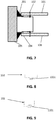
- the first support element 102 is a support element which is made weaker than the support elements used in the remainder part of the gypsum wall. Two examples of how the support element can be provided with a weaker portion are shown in FIG. 8 and FIG. 9 .
- the first stud 102 is a stud with two symmetric separable parts connected by glue 1001, the zone where the parts are glued being the weaker zone.
- the first stud 102 is made weaker by introducing a weak point 1101 in the stud that breaks at a specific force level.
- the stud may be made of metal, e.g. steel, although embodiments are not limited thereto.
- the weak point 1101 is, a hole or a plurality of holes, or a perforation, or is created by using another type of material than the stud material.
- the seismic protective structure comprises a wedge 201 which is mounted inside the track 104.
- the wedge 104 mounted inside the track pushes against the first stud 102 thereby breaking the first stud 102 and as such separating the two parts of the first stud 102.
- the pressure on the first support element 102 may additionally or alternatively also induce additional stress in the gypsum board, thus resulting in the breaking of the gypsum board.
- FIG. 11 illustrates an exemplary embodiment of the current invention whereby the track 104 has a wedge 201 with a triangular cross-section.
- the first stud 102 When mounted, the first stud 102 is on the inside of the track 104 and the protective board 101 is on the outside of the track.
- the triangular shape of the wedge 201 will push the protective board 101 away from the first stud. If the displacement between the track 104 and the protective stud 102 is high enough the protective board 101 will be completely separated from the first stud 102.
- the cross-section of the wedge 201 not necessarily needs to be triangular. Any other shape of the cross-section enabling the wedge 201 to separate the first stud from the protective board is possible as an embodiment of the current invention.
- FIG. 12 shows cross-sections of wedges 201 that can be used in some embodiments according to the present invention.
- These wedges 201 can for example be mounted inside the track 104, against the structural wall 105, and push, during an earthquake, against the first stud 102 breaking it at a certain force or deforming it such that damage to the gypsum board is caused. It is an advantage of embodiments of the current invention that this force is below the force required to break the rest of the board partition wall, thus preventing the rest of the gypsum board partition to be damaged.
- the first stud 102 may be made weaker than the second stud 103.
- FIG. 13 illustrates cross-sections of an integrated track 104 and wedge 201 according to some embodiments of the present invention.
- the track 104 being a guidance for the first stud 102, has a form such that during an earthquake it exercises a pressure on the first stud 102, causing the first stud 102 to break if the displacement of the track 104 with regard to the first stud 102 is high enough.
- the wedge 201 may have a triangular form or may exist of several pressure points or may have another form for efficiently breaking the first stud 102.
- the first stud 102 and the wedge 201 are integrated into one piece.
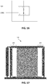
- the gypsum board 101 will move over the wedge 201.
- the protective board 101 will break. This process is illustrated in FIG. 15 .
- the integration of the 3 different parts has as advantage that mounting of the protective structure becomes easier and less error prone.
- the gypsum board 101 is connected with the second stud 103 such that it can rotate around an axis parallel with the axis of the second stud 103. Therefore a rotating suspension 1901 is foreseen.
- the rotating suspension 1901 may comprise an additional board fixed to the protective board 101 and another board fixed to the board on the other side of the second stud 103 to increase the strength of the suspension 109.
- the extra boards can be used as fixation points for a hinge.
- the ability of the gypsum board 101 of rotating prevents it from falling down when the connection between the first stud 102 and the gypsum board 101 is broken. When detached from the first stud 102 the gypsum board rotates by means of the rotating suspension 1901. It is an advantage of embodiments of the current invention that the protective board 101, after being disconnected from the first stud 102, does not fall on the ground.
- the gypsum board 101 is made of the same material as the other gypsum boards, resulting in the advantage that standard available gypsum boards can be used.
- the first support element is adapted for, upon a given level of seismic action, inducing a force on the at least one gypsum board.
- the first support element 102 therefore may be adapted with a stress inducing means that is deformable when a given level of seismic action occurs and that in deformed state provides a pressure on one or more gypsum boards and the one or more gypsum boards are broken.
- the board may be an edge board but does not need to be.
- the system also may be introduced at another position - away from the edge of the partition board - in the partition board for breaking a board at that other position preferentially over the other boards. Except for the change in position, the same principles and features apply.
- the present invention relates to a board partition comprising a seismic protective structure as described in the first aspect.
- the board partition may comprise a seismic protective structure at both ends of the board partition. It is an advantage of embodiments of the current invention that the board partition comprising the protective structure separates two rooms effectively with regard to fire and with regard to acoustics.
- the present invention relates a kit of parts for constructing or restoring a seismic protective structure as described above.
- the kit of parts comprises one or more of a track element, a first support element and at least one board.
- the kit of parts can for example also comprise a stress inducing means for, when mounted in the seismic protective structure, introducing, when a given level of seismic stress is appearing on the board partition (190), additional stress on the at least one board (101) and/or on the first substantially vertical support element (102) for causing the seismic protective structure (100) to damage before the rest of the board partition (190) breaks.
- the board may comprise a weaker portion such that, when a given level of seismic stress is appearing on the board partition, the board will break at the weaker portion.
- the track element or the first support element may comprise the stress inducing means according to an embodiment as described for the first aspect.
- the present invention relates to a method for protecting a board partition against a given level of seismic stress, the method comprising using a seismic protective structure in the board partition such that, when a given level of seismic stress is appearing, damage is intentionally caused to at least one board of the seismic protective structure thereby releasing pressure from the remainder of the board partition.
- a method for restoring a board partition is disclosed, wherein the method comprises replacing one or more of the board and a first support element for restoring the board partition.
Landscapes
- Engineering & Computer Science (AREA)
- Architecture (AREA)
- Civil Engineering (AREA)
- Structural Engineering (AREA)
- Physics & Mathematics (AREA)
- Electromagnetism (AREA)
- Environmental & Geological Engineering (AREA)
- Business, Economics & Management (AREA)
- Emergency Management (AREA)
- Building Environments (AREA)
- Buildings Adapted To Withstand Abnormal External Influences (AREA)
- Bridges Or Land Bridges (AREA)
- Devices Affording Protection Of Roads Or Walls For Sound Insulation (AREA)
Claims (15)
- Structure de protection sismique (100) destinée à former une partie d'une cloison en panneaux (190), la structure de protection sismique (100) comprenant :- au moins un panneau (101),- un premier élément de support (102) pour y fixer l'au moins un panneau (101) et pour positionner l'au moins un panneau (101) dans la cloison en panneaux adjacent à un mur contigu voisin de la cloison en panneaux,- un élément de rail (104) pouvant être fixé au mur contigu voisin de la cloison en panneaux (190), l'élément de rail (104) étant adapté pour y positionner de façon mobile le premier élément de support (102),- un deuxième élément de support (103) pour relier l'au moins un panneau (101) au reste de la cloison en panneaux (190),caractérisée en ce que la structure de protection sismique (100) est adaptée pour, quand un niveau donné de contraintes sismiques apparaît, causer intentionnellement des dommages à l'au moins un panneau (101) pour relâcher ainsi les contraintes du reste de la cloison en panneaux (190).
- Structure de protection sismique (100) selon la revendication 1, la structure de protection sismique (100) comprenant un élément induisant des contraintes (201) pour introduire, quand un niveau donné de contraintes sismiques apparaît sur la cloison en panneaux (190), des contraintes supplémentaires sur l'au moins un panneau (101) et/ou le premier élément de support (102) pour faire en sorte que la structure de protection sismique (100) s'endommage avant que le reste de la cloison en panneaux (190) rompe.
- Structure de protection sismique (100) selon la revendication 2, dans laquelle l'élément induisant des contraintes (201) comprend au moins une cale (201) façonnée et positionnée pour, lors d'un déplacement relatif donné de l'élément de rail (104) et du premier élément de support (102), se décaler entre le premier élément de support (102) et le panneau (101) pour séparer le panneau (101) du premier élément de support (102).
- Structure de protection sismique selon la revendication 3, dans laquelle l'élément de rail (104) est adapté en forme à une saillie pour espacer le panneau (101) et le premier élément de support (102) avec un espace pour, lors d'un déplacement relatif donné de l'élément de rail (104) et du premier élément de support (102), introduire la cale (201) entre le panneau (101) et le premier élément de support (102).
- Structure de protection sismique selon l'une quelconque des revendications précédentes, dans laquelle le premier élément de support (102) comprend une partie faible pour la rupture du premier élément de support (102) lorsqu'un niveau donné de contraintes sismiques apparaît.
- Structure de protection sismique (100) selon la revendication 5, dans laquelle le premier élément de support (102) comprend deux sous-éléments, éventuellement sensiblement symétriques, collés l'un à l'autre, la partie faible correspondant à la zone de collage où les sous-éléments sont collés l'un à l'autre.
- Structure de protection sismique (100) selon l'une quelconque des revendications 4 ou 5 dans la mesure où elles sont dépendantes de la revendication 2, dans laquelle le moyen induisant des contraintes comprend un élément induisant des contraintes montable ou monté sur le rail pour induire des contraintes sur le premier élément de support (102), quand le rail se déplace de façon relative par rapport au premier élément de support (102) sous l'influence d'un tremblement de terre.
- Structure de protection sismique (100) selon l'une quelconque des revendications précédentes, dans laquelle le premier élément de support (102) comprend un moyen induisant une pression se déformant sous l'influence d'un niveau donné de contraintes sismiques sur le mur de cloison en panneaux de telle sorte que ledit moyen induisant une pression déformé induit une pression sur l'au moins un panneau pour rompre le panneau.
- Structure de protection sismique (100) selon l'une quelconque des revendications précédentes, dans laquelle l'au moins un panneau de bord (101) comprend une partie plus faible de telle sorte que, quand un niveau donné de contraintes sismiques apparaîtra sur la cloison en panneaux (190), le panneau (101) se rompra dans la partie plus faible.
- Structure de protection sismique (100) selon l'une quelconque des revendications précédentes, dans laquelle le panneau (101) est fixé par une suspension rotative (1901) au deuxième élément de support ou un autre panneau de la cloison en panneaux (102).
- Structure de protection sismique (100) selon l'une quelconque des revendications précédentes, dans laquelle le panneau est un panneau de plâtre (101).
- Cloison en panneaux (190) comprenant une structure de protection sismique selon l'une quelconque des revendications 1 à 11.
- Kit de pièces destiné à construire une structure de protection sismique selon l'une quelconque des revendications 1 à 11, le kit de pièces comprenant un ou plusieurs éléments parmi un élément de rail (104), un premier élément de support (102) et au moins un panneau (101),
dans lequel- le kit de pièces comprend également un moyen induisant des contraintes (201) pour, quand il est monté dans la structure de protection sismique, introduire, quand un niveau donné de contraintes sismiques apparaît sur la cloison en panneaux (190), des contraintes supplémentaires sur l'au moins un panneau (101) et/ou sur le premier élément de support (102) pour faire en sorte que la structure de protection sismique (100) s'endommage avant que le reste du mur de cloison en panneaux (190) rompe, et/ou- dans lequel l'au moins un panneau (101) comprend une partie plus faible de telle sorte que, quand un niveau donné de contraintes sismiques apparaîtra sur la cloison en panneaux (190), le panneau (101) rompra dans la partie plus faible. - Procédé de protection d'une cloison en panneaux (190) contre un niveau donné de contraintes sismiques, le procédé comprenant l'utilisation d'une structure de protection sismique (100) selon l'une quelconque des revendications 1 à 11 dans la cloison en panneaux de telle sorte que, quand un niveau donné de contraintes sismiques apparaît, des dommages sont intentionnellement causés à l'au moins un panneau (101) de la structure de protection sismique (100), relâchant ainsi la pression du reste de la cloison en panneaux (190).
- Procédé de restauration d'une cloison en panneaux après un tremblement de terre, la cloison en panneaux comprenant une structure de protection sismique telle que décrite dans les revendications 1 à 11, le procédé comprenant le remplacement d'un ou plusieurs des panneaux et d'un premier élément de support pour restaurer la cloison en panneaux.
Priority Applications (2)
| Application Number | Priority Date | Filing Date | Title |
|---|---|---|---|
| PL14825327T PL3084103T3 (pl) | 2013-12-20 | 2014-12-19 | Konstrukcja zabezpieczająca dla ścianek działowych z płyt |
| EP14825327.1A EP3084103B1 (fr) | 2013-12-20 | 2014-12-19 | Structure de protection pour partitions de panneaux |
Applications Claiming Priority (3)
| Application Number | Priority Date | Filing Date | Title |
|---|---|---|---|
| EP13290326.1A EP2886748A1 (fr) | 2013-12-20 | 2013-12-20 | Structure de protection pour partitions de panneaux |
| PCT/EP2014/078829 WO2015091997A1 (fr) | 2013-12-20 | 2014-12-19 | Structure de protection pour cloisons de planches |
| EP14825327.1A EP3084103B1 (fr) | 2013-12-20 | 2014-12-19 | Structure de protection pour partitions de panneaux |
Publications (2)
| Publication Number | Publication Date |
|---|---|
| EP3084103A1 EP3084103A1 (fr) | 2016-10-26 |
| EP3084103B1 true EP3084103B1 (fr) | 2017-11-15 |
Family
ID=49958205
Family Applications (2)
| Application Number | Title | Priority Date | Filing Date |
|---|---|---|---|
| EP13290326.1A Ceased EP2886748A1 (fr) | 2013-12-20 | 2013-12-20 | Structure de protection pour partitions de panneaux |
| EP14825327.1A Active EP3084103B1 (fr) | 2013-12-20 | 2014-12-19 | Structure de protection pour partitions de panneaux |
Family Applications Before (1)
| Application Number | Title | Priority Date | Filing Date |
|---|---|---|---|
| EP13290326.1A Ceased EP2886748A1 (fr) | 2013-12-20 | 2013-12-20 | Structure de protection pour partitions de panneaux |
Country Status (12)
| Country | Link |
|---|---|
| US (2) | US10119268B2 (fr) |
| EP (2) | EP2886748A1 (fr) |
| AU (1) | AU2014368356B2 (fr) |
| BR (1) | BR112016012722A2 (fr) |
| CL (1) | CL2016001471A1 (fr) |
| DK (1) | DK3084103T3 (fr) |
| ES (1) | ES2659071T3 (fr) |
| PE (1) | PE20161075A1 (fr) |
| PL (1) | PL3084103T3 (fr) |
| RU (1) | RU2016128567A (fr) |
| UA (1) | UA116589C2 (fr) |
| WO (1) | WO2015091997A1 (fr) |
Families Citing this family (6)
| Publication number | Priority date | Publication date | Assignee | Title |
|---|---|---|---|---|
| EP2886732A1 (fr) * | 2013-12-20 | 2015-06-24 | Siniat International SAS | Système de réduction de dommage sismique pour partitions |
| WO2016096162A1 (fr) | 2014-12-19 | 2016-06-23 | Siniat International Sas | Structure de protection antisismique pour cloisons en panneaux |
| JP7336787B2 (ja) * | 2019-01-22 | 2023-09-01 | 岡部株式会社 | 木質構造体用制振部材及び木質構造体の制振構造 |
| WO2021171305A1 (fr) | 2020-02-26 | 2021-09-02 | Saint-Gobain Placo | Goujon de guidage et structure de paroi de séparation correspondante |
| NL1043636B1 (nl) * | 2020-04-23 | 2021-11-01 | Comforthome B V | Smeltzekering |
| ES2963020B2 (es) | 2023-11-06 | 2024-11-12 | Univ Valencia Politecnica | Placa de construccion, no estructural, aislada sismicamente y panel de construccion no estructural, aislado sismicamente, que comprende dicha placa |
Family Cites Families (53)
| Publication number | Priority date | Publication date | Assignee | Title |
|---|---|---|---|---|
| US2235761A (en) * | 1938-03-02 | 1941-03-18 | William M Goldsmith | Partition structure |
| US2315687A (en) * | 1939-07-24 | 1943-04-06 | Edmund P Burke | Construction unit |
| US2796158A (en) * | 1947-10-22 | 1957-06-18 | Johns Manville | Wall assembly |
| US3388521A (en) * | 1962-12-28 | 1968-06-18 | Kaiser Gypsum Co | Construction |
| US3332188A (en) * | 1964-12-08 | 1967-07-25 | Otto W Schaefer | Plaster wall frame structure with stud securing clips |
| US3759001A (en) * | 1971-09-23 | 1973-09-18 | Eastern Prod Corp | Demountable wall construction |
| US4112636A (en) * | 1975-03-14 | 1978-09-12 | Hays Joseph C | Wallboard laminating clip |
| NZ184815A (en) * | 1976-08-06 | 1981-12-15 | F Saunders | Joining composite building panels |
| DE2836126A1 (de) * | 1978-08-18 | 1980-02-28 | Vki Rheinhold & Mahla Ag | Anschlussbausatz fuer trennwaende und zweischalige demontierbare trennwand mit anschlusselement. |
| JPH061520B2 (ja) | 1987-07-20 | 1994-01-05 | 新明和工業株式会社 | 駐車設備の出庫予約装置 |
| US4959934A (en) * | 1988-01-27 | 1990-10-02 | Kajima Corporation | Elasto-plastic damper for use in structure |
| JP2671904B2 (ja) * | 1989-08-04 | 1997-11-05 | 鹿島建設株式会社 | ボルト型弾塑性ダンパーおよび建物の部材接合部 |
| US5040345A (en) * | 1990-04-27 | 1991-08-20 | Gilmour Michael F | Stud clip for allowing vertical floating movement of a floor or roof structure |
| GB2265169B (en) * | 1992-03-20 | 1996-05-15 | Fu Chuan Chang | A shock absorption wall structure and method of producing the same |
| US5222335A (en) * | 1992-06-26 | 1993-06-29 | Anthony Petrecca | Metal track system for metal studs |
| JPH0849328A (ja) * | 1994-08-05 | 1996-02-20 | Okabe Co Ltd | 間仕切壁 |
| JPH09242183A (ja) * | 1996-03-11 | 1997-09-16 | Tomoe Corp | 枠組み耐震構造 |
| US6250042B1 (en) * | 1996-06-17 | 2001-06-26 | University Of Central Florida | Additional metal and wood composite framing members for residential and light commercial construction |
| JPH1121984A (ja) * | 1997-07-01 | 1999-01-26 | Kajima Corp | 補強ボックスカルバート |
| US6210066B1 (en) * | 1998-10-27 | 2001-04-03 | Clifford Dent | Breakaway bracket assembly |
| JP3988781B2 (ja) * | 1999-03-05 | 2007-10-10 | 清水建設株式会社 | 間仕切壁構造およびそれに用いるランナー |
| US6854237B2 (en) * | 1999-04-16 | 2005-02-15 | Steeler Inc. | Structural walls |
| US6374558B1 (en) * | 1999-04-16 | 2002-04-23 | Matt Surowiecki | Wall beam and stud |
| WO2001073238A2 (fr) * | 2000-03-29 | 2001-10-04 | The Research Foundation Of The State University Of New York At Buffalo | Appareil de dissipation de l'energie sismique hautement efficace |
| US20030196401A1 (en) * | 2002-04-17 | 2003-10-23 | Matt Surowiecki | Wall construction |
| US20050086895A1 (en) * | 2003-10-27 | 2005-04-28 | Elliot A. C. | Compression post for structural shear wall |
| FR2863284B1 (fr) * | 2003-12-05 | 2007-11-23 | Placoplatre Sa | Dispositif pour le montage parasismique d'une cloison |
| US7832171B2 (en) * | 2003-12-12 | 2010-11-16 | Dennis Erickson | Construction framing system and track therefor |
| US8001734B2 (en) * | 2004-05-18 | 2011-08-23 | Simpson Strong-Tie Co., Inc. | Moment frame links wall |
| US20060032157A1 (en) * | 2004-07-30 | 2006-02-16 | Mareck Baryla | Seismic wall system |
| US8181404B2 (en) * | 2004-12-20 | 2012-05-22 | James Alan Klein | Head-of-wall fireblocks and related wall assemblies |
| US7451573B2 (en) * | 2005-02-25 | 2008-11-18 | Leszek Orszulak | Slotted M-track beam structures and related wall assemblies |
| US20080148681A1 (en) * | 2006-12-22 | 2008-06-26 | Badri Hiriyur | Moment frame connector |
| US7735295B2 (en) * | 2007-02-15 | 2010-06-15 | Surowiecki Matt F | Slotted track with double-ply sidewalls |
| US8499512B2 (en) * | 2008-01-16 | 2013-08-06 | California Expanded Metal Products Company | Exterior wall construction product |
| US20110225915A1 (en) * | 2007-12-20 | 2011-09-22 | Specialty Hardware L.P. | Energy absorbing blast wall for building structure |
| US8079188B2 (en) * | 2007-12-20 | 2011-12-20 | Specialty Hardware L.P. | Energy absorbing blast wall for building structure |
| WO2009089200A2 (fr) * | 2008-01-11 | 2009-07-16 | Quality Edge, Inc. | Procédé et système de mur démontable |
| TWI396790B (zh) * | 2008-01-24 | 2013-05-21 | Nippon Steel & Sumitomo Metal Corp | 接合金屬件及具有該金屬件之建築物 |
| US8061099B2 (en) * | 2009-05-19 | 2011-11-22 | Tsf Systems, Llc | Vertical deflection extension end member |
| US8671632B2 (en) * | 2009-09-21 | 2014-03-18 | California Expanded Metal Products Company | Wall gap fire block device, system and method |
| JP2011162938A (ja) * | 2010-02-04 | 2011-08-25 | Kameyama Kensetsu Kk | 木造建築における耐震構造 |
| US8640415B2 (en) * | 2010-04-08 | 2014-02-04 | California Expanded Metal Products Company | Fire-rated wall construction product |
| CA2751858C (fr) * | 2010-09-09 | 2020-06-09 | Michael Hatzinikolas | Element fonctionnel porteur a degagement automatique |
| US8490341B2 (en) * | 2010-09-09 | 2013-07-23 | Michael Hatzinikolas | Self-releasing structural assembly |
| JP5941927B2 (ja) * | 2011-01-14 | 2016-06-29 | クリストポロス、コンスタンティンCHRISTOPOULOS,Constantin | 建築構造物における振動を減衰させる接続部材 |
| UA108555C2 (en) * | 2011-03-30 | 2015-05-12 | Siniat Int Sas | Improving belonging to construction |
| WO2013057384A1 (fr) * | 2011-10-17 | 2013-04-25 | Lafarge Gypsum International | Cloison parasismique |
| US8844205B2 (en) * | 2012-01-06 | 2014-09-30 | The Penn State Research Foundation | Compressed elastomer damper for earthquake hazard reduction |
| US9145906B2 (en) * | 2012-10-16 | 2015-09-29 | Unitrac, Inc. | Slide-on structural positioner |
| EP2886732A1 (fr) * | 2013-12-20 | 2015-06-24 | Siniat International SAS | Système de réduction de dommage sismique pour partitions |
| US9512614B2 (en) * | 2014-07-21 | 2016-12-06 | Hilti Aktiengesellschaft | Insulating sealing element for construction joints |
| WO2016096162A1 (fr) * | 2014-12-19 | 2016-06-23 | Siniat International Sas | Structure de protection antisismique pour cloisons en panneaux |
-
2013
- 2013-12-20 EP EP13290326.1A patent/EP2886748A1/fr not_active Ceased
-
2014
- 2014-12-19 AU AU2014368356A patent/AU2014368356B2/en active Active
- 2014-12-19 US US15/105,407 patent/US10119268B2/en active Active
- 2014-12-19 RU RU2016128567A patent/RU2016128567A/ru unknown
- 2014-12-19 UA UAA201607762A patent/UA116589C2/uk unknown
- 2014-12-19 BR BR112016012722A patent/BR112016012722A2/pt not_active Application Discontinuation
- 2014-12-19 PE PE2016000759A patent/PE20161075A1/es unknown
- 2014-12-19 ES ES14825327.1T patent/ES2659071T3/es active Active
- 2014-12-19 PL PL14825327T patent/PL3084103T3/pl unknown
- 2014-12-19 WO PCT/EP2014/078829 patent/WO2015091997A1/fr not_active Ceased
- 2014-12-19 EP EP14825327.1A patent/EP3084103B1/fr active Active
- 2014-12-19 DK DK14825327.1T patent/DK3084103T3/en active
-
2016
- 2016-06-13 CL CL2016001471A patent/CL2016001471A1/es unknown
-
2018
- 2018-09-28 US US16/145,552 patent/US20190100909A1/en not_active Abandoned
Non-Patent Citations (1)
| Title |
|---|
| None * |
Also Published As
| Publication number | Publication date |
|---|---|
| AU2014368356B2 (en) | 2017-12-21 |
| WO2015091997A1 (fr) | 2015-06-25 |
| AU2014368356A1 (en) | 2016-06-16 |
| US20190100909A1 (en) | 2019-04-04 |
| EP2886748A1 (fr) | 2015-06-24 |
| CL2016001471A1 (es) | 2017-01-20 |
| PL3084103T3 (pl) | 2018-05-30 |
| PE20161075A1 (es) | 2016-10-28 |
| BR112016012722A2 (pt) | 2017-08-08 |
| US20160319539A1 (en) | 2016-11-03 |
| DK3084103T3 (en) | 2018-02-12 |
| UA116589C2 (uk) | 2018-04-10 |
| US10119268B2 (en) | 2018-11-06 |
| RU2016128567A (ru) | 2018-01-25 |
| EP3084103A1 (fr) | 2016-10-26 |
| ES2659071T3 (es) | 2018-03-13 |
Similar Documents
| Publication | Publication Date | Title |
|---|---|---|
| US20190100909A1 (en) | Protective structure for board partitions | |
| AU2015367790B2 (en) | Seismic protective structure for board partitions | |
| EP3084094B1 (fr) | Systeme de reduction de dommage sismique pour murs de separartion | |
| KR101842593B1 (ko) | 제진장치 설치공법 | |
| JP2016023476A (ja) | コンクリート構造物耐震及び制振補強用型枠およびそれを用いたコンクリート構造物耐震及び制振補強工法 | |
| KR101015925B1 (ko) | 길이 가변이 가능한 내진보강 프레임 | |
| JP2018062823A (ja) | 免震構造 | |
| KR102020389B1 (ko) | 조립식 패널지지장치 및, 패널구조체 | |
| JP7079623B2 (ja) | 木造建築物の補強構造及び補強方法 | |
| CN216665181U (zh) | 一种装配式的减震结构及可恢复功能的剪力墙 | |
| JP6669088B2 (ja) | 鋼板耐震壁、耐震フレームおよびこれを備えた建物 | |
| JP6886270B2 (ja) | 耐震用スリット材の設置構造および耐震用スリット材の施工方法 | |
| CN215519343U (zh) | 一种装配式框架-减震墙板的组合结构及其连接件 | |
| JP6696744B2 (ja) | 吊り天井補強構造 | |
| JP2019173291A (ja) | 耐震壁 | |
| KR20170079105A (ko) | 클램프 일체형 내진행거 | |
| JP2006241783A (ja) | 建物の制震構造 | |
| JP2016056660A (ja) | 吊り天井補強用金具 | |
| IT201800006106A1 (it) | Dispositivo e sistema antisismico per edifici | |
| IT201600087913A1 (it) | Dispositivo e sistema antisismico per edifici | |
| JP2018193747A (ja) | 床施工方法及びスペーサー金具 | |
| JP2016070036A (ja) | 間仕切壁の耐震支持構造 |
Legal Events
| Date | Code | Title | Description |
|---|---|---|---|
| PUAI | Public reference made under article 153(3) epc to a published international application that has entered the european phase |
Free format text: ORIGINAL CODE: 0009012 |
|
| 17P | Request for examination filed |
Effective date: 20160614 |
|
| AK | Designated contracting states |
Kind code of ref document: A1 Designated state(s): AL AT BE BG CH CY CZ DE DK EE ES FI FR GB GR HR HU IE IS IT LI LT LU LV MC MK MT NL NO PL PT RO RS SE SI SK SM TR |
|
| AX | Request for extension of the european patent |
Extension state: BA ME |
|
| RAP1 | Party data changed (applicant data changed or rights of an application transferred) |
Owner name: ETEX BUILDING PERFORMANCE INTERNATIONAL SAS |
|
| DAX | Request for extension of the european patent (deleted) | ||
| GRAP | Despatch of communication of intention to grant a patent |
Free format text: ORIGINAL CODE: EPIDOSNIGR1 |
|
| RIC1 | Information provided on ipc code assigned before grant |
Ipc: E04H 9/02 20060101AFI20170516BHEP Ipc: E04B 2/74 20060101ALI20170516BHEP Ipc: E04B 2/72 20060101ALI20170516BHEP Ipc: E04B 2/82 20060101ALI20170516BHEP Ipc: E04B 1/98 20060101ALI20170516BHEP |
|
| INTG | Intention to grant announced |
Effective date: 20170622 |
|
| GRAS | Grant fee paid |
Free format text: ORIGINAL CODE: EPIDOSNIGR3 |
|
| GRAA | (expected) grant |
Free format text: ORIGINAL CODE: 0009210 |
|
| AK | Designated contracting states |
Kind code of ref document: B1 Designated state(s): AL AT BE BG CH CY CZ DE DK EE ES FI FR GB GR HR HU IE IS IT LI LT LU LV MC MK MT NL NO PL PT RO RS SE SI SK SM TR |
|
| REG | Reference to a national code |
Ref country code: AT Ref legal event code: REF Ref document number: 946437 Country of ref document: AT Kind code of ref document: T Effective date: 20171115 Ref country code: GB Ref legal event code: FG4D Ref country code: CH Ref legal event code: EP |
|
| REG | Reference to a national code |
Ref country code: IE Ref legal event code: FG4D |
|
| REG | Reference to a national code |
Ref country code: FR Ref legal event code: PLFP Year of fee payment: 4 |
|
| REG | Reference to a national code |
Ref country code: DE Ref legal event code: R096 Ref document number: 602014017391 Country of ref document: DE |
|
| REG | Reference to a national code |
Ref country code: RO Ref legal event code: EPE |
|
| REG | Reference to a national code |
Ref country code: DK Ref legal event code: T3 Effective date: 20180206 |
|
| REG | Reference to a national code |
Ref country code: NL Ref legal event code: FP |
|
| REG | Reference to a national code |
Ref country code: ES Ref legal event code: FG2A Ref document number: 2659071 Country of ref document: ES Kind code of ref document: T3 Effective date: 20180313 |
|
| REG | Reference to a national code |
Ref country code: LT Ref legal event code: MG4D |
|
| PG25 | Lapsed in a contracting state [announced via postgrant information from national office to epo] |
Ref country code: SE Free format text: LAPSE BECAUSE OF FAILURE TO SUBMIT A TRANSLATION OF THE DESCRIPTION OR TO PAY THE FEE WITHIN THE PRESCRIBED TIME-LIMIT Effective date: 20171115 Ref country code: LT Free format text: LAPSE BECAUSE OF FAILURE TO SUBMIT A TRANSLATION OF THE DESCRIPTION OR TO PAY THE FEE WITHIN THE PRESCRIBED TIME-LIMIT Effective date: 20171115 Ref country code: FI Free format text: LAPSE BECAUSE OF FAILURE TO SUBMIT A TRANSLATION OF THE DESCRIPTION OR TO PAY THE FEE WITHIN THE PRESCRIBED TIME-LIMIT Effective date: 20171115 Ref country code: NO Free format text: LAPSE BECAUSE OF FAILURE TO SUBMIT A TRANSLATION OF THE DESCRIPTION OR TO PAY THE FEE WITHIN THE PRESCRIBED TIME-LIMIT Effective date: 20180215 |
|
| PG25 | Lapsed in a contracting state [announced via postgrant information from national office to epo] |
Ref country code: LV Free format text: LAPSE BECAUSE OF FAILURE TO SUBMIT A TRANSLATION OF THE DESCRIPTION OR TO PAY THE FEE WITHIN THE PRESCRIBED TIME-LIMIT Effective date: 20171115 Ref country code: RS Free format text: LAPSE BECAUSE OF FAILURE TO SUBMIT A TRANSLATION OF THE DESCRIPTION OR TO PAY THE FEE WITHIN THE PRESCRIBED TIME-LIMIT Effective date: 20171115 Ref country code: BG Free format text: LAPSE BECAUSE OF FAILURE TO SUBMIT A TRANSLATION OF THE DESCRIPTION OR TO PAY THE FEE WITHIN THE PRESCRIBED TIME-LIMIT Effective date: 20180215 Ref country code: GR Free format text: LAPSE BECAUSE OF FAILURE TO SUBMIT A TRANSLATION OF THE DESCRIPTION OR TO PAY THE FEE WITHIN THE PRESCRIBED TIME-LIMIT Effective date: 20180216 Ref country code: HR Free format text: LAPSE BECAUSE OF FAILURE TO SUBMIT A TRANSLATION OF THE DESCRIPTION OR TO PAY THE FEE WITHIN THE PRESCRIBED TIME-LIMIT Effective date: 20171115 |
|
| PG25 | Lapsed in a contracting state [announced via postgrant information from national office to epo] |
Ref country code: CZ Free format text: LAPSE BECAUSE OF FAILURE TO SUBMIT A TRANSLATION OF THE DESCRIPTION OR TO PAY THE FEE WITHIN THE PRESCRIBED TIME-LIMIT Effective date: 20171115 Ref country code: CY Free format text: LAPSE BECAUSE OF FAILURE TO SUBMIT A TRANSLATION OF THE DESCRIPTION OR TO PAY THE FEE WITHIN THE PRESCRIBED TIME-LIMIT Effective date: 20171115 Ref country code: EE Free format text: LAPSE BECAUSE OF FAILURE TO SUBMIT A TRANSLATION OF THE DESCRIPTION OR TO PAY THE FEE WITHIN THE PRESCRIBED TIME-LIMIT Effective date: 20171115 Ref country code: SK Free format text: LAPSE BECAUSE OF FAILURE TO SUBMIT A TRANSLATION OF THE DESCRIPTION OR TO PAY THE FEE WITHIN THE PRESCRIBED TIME-LIMIT Effective date: 20171115 |
|
| REG | Reference to a national code |
Ref country code: CH Ref legal event code: PL |
|
| REG | Reference to a national code |
Ref country code: DE Ref legal event code: R097 Ref document number: 602014017391 Country of ref document: DE |
|
| PG25 | Lapsed in a contracting state [announced via postgrant information from national office to epo] |
Ref country code: SM Free format text: LAPSE BECAUSE OF FAILURE TO SUBMIT A TRANSLATION OF THE DESCRIPTION OR TO PAY THE FEE WITHIN THE PRESCRIBED TIME-LIMIT Effective date: 20171115 |
|
| PLBE | No opposition filed within time limit |
Free format text: ORIGINAL CODE: 0009261 |
|
| STAA | Information on the status of an ep patent application or granted ep patent |
Free format text: STATUS: NO OPPOSITION FILED WITHIN TIME LIMIT |
|
| PG25 | Lapsed in a contracting state [announced via postgrant information from national office to epo] |
Ref country code: MT Free format text: LAPSE BECAUSE OF NON-PAYMENT OF DUE FEES Effective date: 20171219 Ref country code: LU Free format text: LAPSE BECAUSE OF NON-PAYMENT OF DUE FEES Effective date: 20171219 |
|
| 26N | No opposition filed |
Effective date: 20180817 |
|
| PG25 | Lapsed in a contracting state [announced via postgrant information from national office to epo] |
Ref country code: LI Free format text: LAPSE BECAUSE OF NON-PAYMENT OF DUE FEES Effective date: 20171231 Ref country code: CH Free format text: LAPSE BECAUSE OF NON-PAYMENT OF DUE FEES Effective date: 20171231 Ref country code: SI Free format text: LAPSE BECAUSE OF FAILURE TO SUBMIT A TRANSLATION OF THE DESCRIPTION OR TO PAY THE FEE WITHIN THE PRESCRIBED TIME-LIMIT Effective date: 20171115 |
|
| PG25 | Lapsed in a contracting state [announced via postgrant information from national office to epo] |
Ref country code: HU Free format text: LAPSE BECAUSE OF FAILURE TO SUBMIT A TRANSLATION OF THE DESCRIPTION OR TO PAY THE FEE WITHIN THE PRESCRIBED TIME-LIMIT; INVALID AB INITIO Effective date: 20141219 Ref country code: MC Free format text: LAPSE BECAUSE OF FAILURE TO SUBMIT A TRANSLATION OF THE DESCRIPTION OR TO PAY THE FEE WITHIN THE PRESCRIBED TIME-LIMIT Effective date: 20171115 |
|
| REG | Reference to a national code |
Ref country code: AT Ref legal event code: UEP Ref document number: 946437 Country of ref document: AT Kind code of ref document: T Effective date: 20171115 |
|
| PG25 | Lapsed in a contracting state [announced via postgrant information from national office to epo] |
Ref country code: MK Free format text: LAPSE BECAUSE OF FAILURE TO SUBMIT A TRANSLATION OF THE DESCRIPTION OR TO PAY THE FEE WITHIN THE PRESCRIBED TIME-LIMIT Effective date: 20171115 |
|
| PGFP | Annual fee paid to national office [announced via postgrant information from national office to epo] |
Ref country code: IE Payment date: 20191227 Year of fee payment: 6 |
|
| PGFP | Annual fee paid to national office [announced via postgrant information from national office to epo] |
Ref country code: BE Payment date: 20191227 Year of fee payment: 6 Ref country code: PL Payment date: 20191203 Year of fee payment: 6 |
|
| PGFP | Annual fee paid to national office [announced via postgrant information from national office to epo] |
Ref country code: AT Payment date: 20191204 Year of fee payment: 6 |
|
| PGFP | Annual fee paid to national office [announced via postgrant information from national office to epo] |
Ref country code: GB Payment date: 20191227 Year of fee payment: 6 Ref country code: DK Payment date: 20191230 Year of fee payment: 6 Ref country code: DE Payment date: 20191231 Year of fee payment: 6 Ref country code: ES Payment date: 20200102 Year of fee payment: 6 |
|
| PG25 | Lapsed in a contracting state [announced via postgrant information from national office to epo] |
Ref country code: PT Free format text: LAPSE BECAUSE OF FAILURE TO SUBMIT A TRANSLATION OF THE DESCRIPTION OR TO PAY THE FEE WITHIN THE PRESCRIBED TIME-LIMIT Effective date: 20171115 |
|
| PG25 | Lapsed in a contracting state [announced via postgrant information from national office to epo] |
Ref country code: IS Free format text: LAPSE BECAUSE OF FAILURE TO SUBMIT A TRANSLATION OF THE DESCRIPTION OR TO PAY THE FEE WITHIN THE PRESCRIBED TIME-LIMIT Effective date: 20180315 Ref country code: AL Free format text: LAPSE BECAUSE OF FAILURE TO SUBMIT A TRANSLATION OF THE DESCRIPTION OR TO PAY THE FEE WITHIN THE PRESCRIBED TIME-LIMIT Effective date: 20171115 |
|
| REG | Reference to a national code |
Ref country code: DE Ref legal event code: R119 Ref document number: 602014017391 Country of ref document: DE |
|
| REG | Reference to a national code |
Ref country code: DK Ref legal event code: EBP Effective date: 20201231 |
|
| REG | Reference to a national code |
Ref country code: AT Ref legal event code: MM01 Ref document number: 946437 Country of ref document: AT Kind code of ref document: T Effective date: 20201219 |
|
| GBPC | Gb: european patent ceased through non-payment of renewal fee |
Effective date: 20201219 |
|
| REG | Reference to a national code |
Ref country code: BE Ref legal event code: MM Effective date: 20201231 |
|
| PG25 | Lapsed in a contracting state [announced via postgrant information from national office to epo] |
Ref country code: IE Free format text: LAPSE BECAUSE OF NON-PAYMENT OF DUE FEES Effective date: 20201219 Ref country code: AT Free format text: LAPSE BECAUSE OF NON-PAYMENT OF DUE FEES Effective date: 20201219 |
|
| PG25 | Lapsed in a contracting state [announced via postgrant information from national office to epo] |
Ref country code: GB Free format text: LAPSE BECAUSE OF NON-PAYMENT OF DUE FEES Effective date: 20201219 Ref country code: DE Free format text: LAPSE BECAUSE OF NON-PAYMENT OF DUE FEES Effective date: 20210701 |
|
| PG25 | Lapsed in a contracting state [announced via postgrant information from national office to epo] |
Ref country code: DK Free format text: LAPSE BECAUSE OF NON-PAYMENT OF DUE FEES Effective date: 20201231 |
|
| REG | Reference to a national code |
Ref country code: ES Ref legal event code: FD2A Effective date: 20220221 |
|
| PG25 | Lapsed in a contracting state [announced via postgrant information from national office to epo] |
Ref country code: ES Free format text: LAPSE BECAUSE OF NON-PAYMENT OF DUE FEES Effective date: 20201220 |
|
| PG25 | Lapsed in a contracting state [announced via postgrant information from national office to epo] |
Ref country code: BE Free format text: LAPSE BECAUSE OF NON-PAYMENT OF DUE FEES Effective date: 20201231 |
|
| PG25 | Lapsed in a contracting state [announced via postgrant information from national office to epo] |
Ref country code: PL Free format text: LAPSE BECAUSE OF NON-PAYMENT OF DUE FEES Effective date: 20201219 |
|
| P01 | Opt-out of the competence of the unified patent court (upc) registered |
Effective date: 20230619 |
|
| PGFP | Annual fee paid to national office [announced via postgrant information from national office to epo] |
Ref country code: TR Payment date: 20231218 Year of fee payment: 10 |
|
| PGFP | Annual fee paid to national office [announced via postgrant information from national office to epo] |
Ref country code: IT Payment date: 20251223 Year of fee payment: 12 |
|
| PGFP | Annual fee paid to national office [announced via postgrant information from national office to epo] |
Ref country code: NL Payment date: 20251219 Year of fee payment: 12 Ref country code: FR Payment date: 20251223 Year of fee payment: 12 |
|
| PGFP | Annual fee paid to national office [announced via postgrant information from national office to epo] |
Ref country code: RO Payment date: 20251216 Year of fee payment: 12 |