EP3084126B1 - Pompe oscillante avec arbre monté dans le stator - Google Patents
Pompe oscillante avec arbre monté dans le stator Download PDFInfo
- Publication number
- EP3084126B1 EP3084126B1 EP14799383.6A EP14799383A EP3084126B1 EP 3084126 B1 EP3084126 B1 EP 3084126B1 EP 14799383 A EP14799383 A EP 14799383A EP 3084126 B1 EP3084126 B1 EP 3084126B1
- Authority
- EP
- European Patent Office
- Prior art keywords
- pump
- drive shaft
- stator
- rotor
- shaft
- Prior art date
- Legal status (The legal status is an assumption and is not a legal conclusion. Google has not performed a legal analysis and makes no representation as to the accuracy of the status listed.)
- Active
Links
Images


Classifications
-
- F—MECHANICAL ENGINEERING; LIGHTING; HEATING; WEAPONS; BLASTING
- F04—POSITIVE - DISPLACEMENT MACHINES FOR LIQUIDS; PUMPS FOR LIQUIDS OR ELASTIC FLUIDS
- F04C—ROTARY-PISTON, OR OSCILLATING-PISTON, POSITIVE-DISPLACEMENT MACHINES FOR LIQUIDS; ROTARY-PISTON, OR OSCILLATING-PISTON, POSITIVE-DISPLACEMENT PUMPS
- F04C3/00—Rotary-piston machines or pumps, with non-parallel axes of movement of co-operating members, e.g. of screw type
- F04C3/06—Rotary-piston machines or pumps, with non-parallel axes of movement of co-operating members, e.g. of screw type the axes being arranged otherwise than at an angle of 90 degrees
- F04C3/08—Rotary-piston machines or pumps, with non-parallel axes of movement of co-operating members, e.g. of screw type the axes being arranged otherwise than at an angle of 90 degrees of intermeshing engagement type, i.e. with engagement of co-operating members similar to that of toothed gearing
-
- F—MECHANICAL ENGINEERING; LIGHTING; HEATING; WEAPONS; BLASTING
- F01—MACHINES OR ENGINES IN GENERAL; ENGINE PLANTS IN GENERAL; STEAM ENGINES
- F01C—ROTARY-PISTON OR OSCILLATING-PISTON MACHINES OR ENGINES
- F01C1/00—Rotary-piston machines or engines
- F01C1/08—Rotary-piston machines or engines of intermeshing engagement type, i.e. with engagement of co- operating members similar to that of toothed gearing
- F01C1/082—Details specially related to intermeshing engagement type machines or engines
- F01C1/084—Toothed wheels
-
- F—MECHANICAL ENGINEERING; LIGHTING; HEATING; WEAPONS; BLASTING
- F01—MACHINES OR ENGINES IN GENERAL; ENGINE PLANTS IN GENERAL; STEAM ENGINES
- F01C—ROTARY-PISTON OR OSCILLATING-PISTON MACHINES OR ENGINES
- F01C3/00—Rotary-piston machines or engines with non-parallel axes of movement of co-operating members
- F01C3/06—Rotary-piston machines or engines with non-parallel axes of movement of co-operating members the axes being arranged otherwise than at an angle of 90 degrees
- F01C3/08—Rotary-piston machines or engines with non-parallel axes of movement of co-operating members the axes being arranged otherwise than at an angle of 90 degrees of intermeshing-engagement type, i.e. with engagement of co-operating members similar to that of toothed gearing
- F01C3/085—Rotary-piston machines or engines with non-parallel axes of movement of co-operating members the axes being arranged otherwise than at an angle of 90 degrees of intermeshing-engagement type, i.e. with engagement of co-operating members similar to that of toothed gearing the axes of cooperating members being on the same plane
-
- F—MECHANICAL ENGINEERING; LIGHTING; HEATING; WEAPONS; BLASTING
- F04—POSITIVE - DISPLACEMENT MACHINES FOR LIQUIDS; PUMPS FOR LIQUIDS OR ELASTIC FLUIDS
- F04C—ROTARY-PISTON, OR OSCILLATING-PISTON, POSITIVE-DISPLACEMENT MACHINES FOR LIQUIDS; ROTARY-PISTON, OR OSCILLATING-PISTON, POSITIVE-DISPLACEMENT PUMPS
- F04C3/00—Rotary-piston machines or pumps, with non-parallel axes of movement of co-operating members, e.g. of screw type
- F04C3/06—Rotary-piston machines or pumps, with non-parallel axes of movement of co-operating members, e.g. of screw type the axes being arranged otherwise than at an angle of 90 degrees
Definitions
- the invention relates to a tumble pump.
- An embodiment of a tumble pump is from the WO 2008/110155 A1 known.
- an offset obliquely on a pump shaft of the tumble pump rotor is rotated by rotation of the pump shaft relative to a pump stator in a tumbling motion, so that formed between the pump rotor and the pump stator pump chambers are increased in volume and reduced.
- These chambers are connected to an input and an output of the tumble pump, so that a fluid is conveyed by the tumble pump.
- WO 2005/024236 discloses a rotary lobe pump with a drive part and a driven part, which rotate about different axes suitable to each other.
- a tumble pump can be provided with a shortened length. Furthermore, friction losses can be reduced with the tumble pump according to the invention.
- the invention relates to a tumbling pump for conveying fluid, for example fuel.
- the tumble pump comprises a pump stator attached to a housing of the tumble pump and a pump rotor guided in the pump stator. which is driven by a drive shaft by means of an oblique end face such that it wobbles with its rotor axis about a drive axis of the drive shaft.
- the drive shaft protrudes through the pump rotor through a through hole and is mounted in a bearing of the pump stator.
- a rotation of the drive shaft may lead to a tumbling of the pump rotor with respect to the Pumpenstators, whereby pump chambers, which are formed between the pump stator and the pump rotor by a toothing, be enlarged and reduced so that a fluid is conveyed by the tumble pump, wherein the pump stator and the pump rotor have a cycloid-shaped toothing.
- the drive shaft is mounted in the pump stator. This storage can be done in the radial and optionally in the radial direction. At a further end (the bearing in the pump stator opposite), the drive shaft is mounted in a housing part of the pump housing. Both bearings, or at least the bearing in the pump stator, can be designed as plain bearings. Thus, on the one hand radial forces can be absorbed by the two bearings and on the other hand, the sealing function can be decoupled between the mounted on the drive shaft pump shaft and the pump housing from the storage.
- the drive shaft can be stored at its ends (and not in the middle), a tilting of the drive shaft can be reduced.
- the bearing in the stator (and also the other bearings) can be designed with a smaller radius than the radius of the pump shaft, which is intended as a sealing point. This can lead to lower slide bearing speeds, which can counteract the generation of heat and friction.
- the oblique end face is provided by a pump shaft, which is positively placed on the drive shaft.
- a positive connection of the pump shaft directly to the drive shaft can spare a driver. Since it is possible to run the pump shaft without contact in the housing, the friction can be reduced.
- the arrangement may also be more resistant to particles that can pass the pump shaft passing through a sealing point, since the use of a metallic sleeve in the housing is possible.
- the drive shaft may have an additional sliding bearing (for example at an end opposite the pump stator). As a result, radial forces of a drive motor can be decoupled from radial forces on the pump shaft.
- the drive shaft carries a rotor of an electric motor as a drive.
- the drive shaft is then mounted in a housing part of the tumble pump, which carries a stator of the electric motor.
- the drive shaft may be a one-piece shaft, which is mounted at its two ends in the stator and in a housing part.
- the tumble pump further comprises a spring for pressing the drive shaft in the direction of the pump stator.
- a spring for pressing the drive shaft in the direction of the pump stator.
- this axial force can be generated by carbon brushes of the electric motor (which have a spring).
- the stator of the electric motor is offset in relation to the rotor of the electric motor in the axial direction such that when operating the motor, the drive shaft is moved by electromagnetic forces in the direction of the pump stator.
- the axial force can also be generated directly by the electric motor, so that it is possible to dispense with a separate spring.
- the drive shaft on two coupled drive shaft parts may support the rotor of an electric motor.
- Another, second part of the drive shaft can carry the pump shaft.
- the second part of the drive shaft may be mounted in the pump stator and in a further housing part.
- the two parts of the drive shaft can be positively coupled by means of a pin. In a two-piece drive shaft radial forces and tilting moments can be particularly well received, since they can be distributed to several bearings for the drive shaft parts.
- the passage opening has inside larger diameter than the drive shaft.
- the pump rotor can tumble around the drive shaft.
- the oblique end face of a drive of the tumble pump away is arranged on a side facing away from the electric motor of the tumble pump pump shaft.
- the toothing of the pump stator faces the electric motor.
- the pump shaft and the pump rotor are accommodated (in this order) between a drive of the pump and the pump stator. In this case, the spherical surfaces of the pump rotor away from the drive.
- the oblique end face to a drive of the tumbling pump is arranged on a side facing the electric motor of the tumble pump side of the pump shaft.
- the toothing of the pump stator is arranged on the side facing away from the electric motor.
- the pump stator, the pump shaft and the pump rotor received (in that order) between a drive and a housing termination.
- the spherical surfaces of the pump rotor point towards the drive.
- One end of the drive shaft may be supported in the housing end part. Further, it is possible that one end of the drive shaft or a drive shaft part is mounted in a further housing part, which also receives a drive of the tumble pump, such as an electric motor.
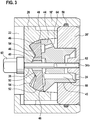
- Fig. 1 shows a tumble pump 10 having a housing 12 which is constructed of a plurality of housing parts, an end portion 14 has an inlet or inlet 16 of the tumble pump 10.
- a support member 16 which is inserted into the end part 14, carries a drive (electric motor) 18 for the tumble pump 10.
- a sealing member 20 provides a seal between a low-pressure region 24 and a high-pressure region 22 and a further end portion 26 serves as a pump stator 28th
- the housing parts 14, 16, 20 and 26 are held together by a metal ring 30.
- a shaft assembly 32 includes a drive shaft 34 which is journaled at one end in the support member 16 and at the other end in the pump stator 28 by means of plain bearings 36,38.
- the one-piece drive shaft 34 carries a rotor 40 of the electric motor 18, which is received in a stator 42 received on the support member 16.
- the drive shaft 34 carries a pump shaft 44 which is positively placed on the drive shaft 34.
- the pump shaft 44 is guided in the sealing part 20 such that a seal between the high-pressure region 22 and the low-pressure region 24 is achieved. Between the pump shaft 44 and the sealing part 20, a further sliding bearing 45 may be formed.
- the pump shaft 34 is an oblique (see Fig. 2 ) End surface 46 which cooperates with a pump rotor 48 and is mechanically coupled thereto.
- the pump rotor 48 and the pump stator 28 provide spherical surfaces 50, 52 which can slide on each other, wherein between the inner spherical surfaces 50 and the outer spherical surfaces 52 by a toothing between the pump rotor 48 and pump stator 28 chambers 54 (see Fig. 3 ) are formed, which increase and decrease upon rotation of the pump rotor 48 in the pump stator 28 and thus unfold a pumping action, so that a fluid from the low-pressure region 24 is conveyed into the high-pressure region 22.
- the pump rotor 48 has on its side facing away from the end face 46 a toothing which meshes with a toothing formed on the pump stator 28. Between the toothing of the pump rotor 48 and the toothing of the pump stator 28, the chambers 54 are formed.
- the toothing of the pump rotor 48 and the toothing of the pump stator 28 are designed, for example, as a cycloidal toothing, but may also be a different toothing.
- the pump rotor has a passage opening 49, through which the drive shaft 34 protrudes.
- the passage opening 49 has a larger diameter than the drive shaft 34 in this area, the drive shaft 34 may, as in the Fig. 1 shown in this area have a smaller diameter than in the region of the pump shaft 44th
- the drive shaft 34 can be acted upon by a spring 51 in the axial direction with force, so that via the (positively connected) pump shaft 44, the pump rotor 48 is pressed against the pump stator 28. This can be done alternatively or additionally by a corresponding offset of the rotor 40 of the electric motor 18 relative to the stator 42.
- the Fig. 2 shows a second embodiment of the tumble pump 10, wherein the components pump shaft 34, pump rotor 48 and pump stator 28 in comparison to the Fig. 1 are arranged vice versa. Furthermore, the drive shaft 34 has two shaft parts 34a and 34b. High pressure and low pressure areas are therefore also arranged in reverse.
- the housing 12 has a carrier part 16 ', which carries the drive 18 or the stator 42, the pump stator 28 and an end part 20', on which the pump stator 28 is seated.
- the opposite end part 14 with the inlet 16 is connected to the support part 16 'by means of an attachment 56.
- the end portion 20 ' has a further seal for the high-pressure region 24 with respect to the environment, which may be realized, for example, with a sealing ring 58 extending between the carrier part 16' and the end part 20 '.
- the drive shaft 34 comprises a first part 34 a, which carries the rotor 40 of the electric motor 18 and which is positively coupled via a pin 60 with a second part 34 b, which carries the pump rotor 48.
- the first part 34a is mounted in the housing 12 by means of a sliding bearing 36.
- the second part 34b is mounted in the stator 28 in a first sliding bearing 38 and in the end part 20 'in a second sliding bearing.
- the Fig. 3 shows a section of a tumble pump analogous to Fig. 2 , It can be seen that the pin 60 may be seated on the drive shaft part 34b on the stator 28 so that the drive shaft part 34b is fixed in an axial direction (away from the drive 18).
- the pump shaft has at least one channel 64 which communicates with the high-pressure region 22 and has at least one channel 66 which communicates with the low-pressure region 24.
- fluid from the low pressure region may flow into a pump chamber 54 via the channel 66, is transported by the rotor about the axis of the shaft, and then forced into the channel 64 by reducing the pumping chamber 54 as the pump rotor 48 is skewed.
Landscapes
- Engineering & Computer Science (AREA)
- Mechanical Engineering (AREA)
- General Engineering & Computer Science (AREA)
- Details And Applications Of Rotary Liquid Pumps (AREA)
- Rotary Pumps (AREA)
Claims (7)
- Pompe oscillante (10), comprenant un stator de pompe (28) fixé à un boîtier (12) de la pompe oscillante; un rotor de pompe (48) guidé dans le stator de pompe (28), qui est entraîné par un arbre d'entraînement (34) portant un rotor d'un moteur électrique au moyen d'une face frontale oblique (46), de telle manière qu'il oscille avec son axe de rotor autour d'un axe d'entraînement de l'arbre d'entraînement (34); dans laquelle le stator de pompe et le rotor de pompe (48) présentent une denture cycloïdale, dans laquelle la face frontale oblique (46) est fournie par un arbre de pompe (44) et est disposée sur un côté de l'arbre de pompe (44) tourné vers le ou détourné du moteur électrique (18) de la pompe oscillante,
caractérisée en ce que l'arbre de pompe (44) présente un passage et l'arbre d'entraînement (34) est engagé par emboîtement dans le passage de l'arbre de pompe (44) et traverse le rotor de pompe (48) à travers une ouverture de passage (49) et est monté dans un palier (38) du stator de pompe (28), en ce que l'ouverture de passage (49) du rotor de pompe (48) présente un plus grand diamètre que l'arbre d'entraînement (34) et en ce que l'arbre d'entraînement (34) est monté par une extrémité opposée au stator de pompe (28) dans une partie de boîtier (16, 16') du boîtier (12). - Pompe oscillante (10) selon la revendication 1, dans laquelle un arbre d'entraînement (34) porte un rotor (40) d'un moteur électrique (18) et l'arbre d'entraînement (34) est monté dans une partie de boîtier (16, 16') de la pompe oscillante, qui porte un stator (42) du moteur électrique (18).
- Pompe oscillante (10) selon l'une quelconque des revendications précédentes, comprenant en outre un ressort (51) pour pousser l'arbre d'entraînement (34) en direction du stator de pompe (28).
- Pompe oscillante (10) selon la revendication 2 ou 3, dans laquelle le stator (42) du moteur électrique (18) est décalé en direction axiale par rapport au rotor (40) du moteur électrique (18), de telle manière que lors du fonctionnement du moteur électrique l'arbre d'entraînement (34) soit déplacé par des forces électromagnétiques en direction du stator de pompe (28).
- Pompe oscillante (10) selon l'une quelconque des revendications précédentes, dans laquelle l'arbre d'entraînement (34) présente deux parties d'arbre d'entraînement (34a, 34b) couplées l'une à l'autre.
- Pompe oscillante (10) selon l'une quelconque des revendications précédentes, dans laquelle le stator de pompe (28), l'arbre de pompe (44) et le rotor de pompe (48), vus dans la direction de l'arbre d'entraînement, sont placés entre le moteur électrique (18) et une partie terminale de boîtier (20'); et dans laquelle l'arbre d'entraînement (34) est monté dans la partie terminale de boîtier (20').
- Pompe oscillante (10) selon l'une quelconque des revendications précédentes, dans laquelle le stator de pompe (28) présente un palier lisse (38) pour l'arbre d'entraînement (34).
Applications Claiming Priority (2)
| Application Number | Priority Date | Filing Date | Title |
|---|---|---|---|
| DE102013226974.9A DE102013226974A1 (de) | 2013-12-20 | 2013-12-20 | Taumelpumpe mit im Stator gelagerter Welle |
| PCT/EP2014/074158 WO2015090730A1 (fr) | 2013-12-20 | 2014-11-10 | Pompe oscillante avec arbre monté dans le stator |
Publications (2)
| Publication Number | Publication Date |
|---|---|
| EP3084126A1 EP3084126A1 (fr) | 2016-10-26 |
| EP3084126B1 true EP3084126B1 (fr) | 2019-02-27 |
Family
ID=51903887
Family Applications (1)
| Application Number | Title | Priority Date | Filing Date |
|---|---|---|---|
| EP14799383.6A Active EP3084126B1 (fr) | 2013-12-20 | 2014-11-10 | Pompe oscillante avec arbre monté dans le stator |
Country Status (3)
| Country | Link |
|---|---|
| EP (1) | EP3084126B1 (fr) |
| DE (1) | DE102013226974A1 (fr) |
| WO (1) | WO2015090730A1 (fr) |
Cited By (1)
| Publication number | Priority date | Publication date | Assignee | Title |
|---|---|---|---|---|
| DE102021115440A1 (de) | 2021-06-15 | 2022-12-15 | Schwäbische Hüttenwerke Automotive GmbH | Rotationspumpe mit einer Axialschubbegrenzungseinrichtung |
Families Citing this family (2)
| Publication number | Priority date | Publication date | Assignee | Title |
|---|---|---|---|---|
| DE102020124825A1 (de) | 2020-09-23 | 2022-03-24 | Kolektor Group D.O.O. | Motor-Pumpe-Einheit |
| DE102021103306A1 (de) | 2021-02-12 | 2022-08-18 | Kolektor Group D.O.O. | Handgeführtes Druckflüssigkeitsgerät |
Citations (1)
| Publication number | Priority date | Publication date | Assignee | Title |
|---|---|---|---|---|
| WO2005024236A1 (fr) * | 2003-09-11 | 2005-03-17 | Cor Pumps + Compressors Ag | Machine a piston rotatif |
Family Cites Families (7)
| Publication number | Priority date | Publication date | Assignee | Title |
|---|---|---|---|---|
| US1965976A (en) * | 1932-04-16 | 1934-07-10 | James L Kempthorne | Mechanism for pumps, compressors, and the like |
| US2380886A (en) * | 1941-12-18 | 1945-07-31 | Hydraulic Dev Corp Inc | Balanced ball type vane pump or motor |
| FR1104109A (fr) * | 1954-04-28 | 1955-11-16 | Rech S Etudes | Perfectionnement apporté à des pompes ou moteurs à fluide à pistons |
| AT322362B (de) * | 1973-03-12 | 1975-05-26 | Keplinger Klaus | Motor und/oder pumpe |
| JP2001200784A (ja) * | 2000-01-19 | 2001-07-27 | Toyota Autom Loom Works Ltd | 斜板式圧縮機 |
| CN101960089B (zh) | 2007-03-13 | 2013-07-31 | 罗伯特·博世有限公司 | 泵或马达 |
| DE102011080803A1 (de) * | 2011-08-11 | 2013-02-14 | Robert Bosch Gmbh | Drehkolbenmaschine, die als Pumpe, Verdichter oder Motor arbeitet |
-
2013
- 2013-12-20 DE DE102013226974.9A patent/DE102013226974A1/de not_active Withdrawn
-
2014
- 2014-11-10 WO PCT/EP2014/074158 patent/WO2015090730A1/fr not_active Ceased
- 2014-11-10 EP EP14799383.6A patent/EP3084126B1/fr active Active
Patent Citations (1)
| Publication number | Priority date | Publication date | Assignee | Title |
|---|---|---|---|---|
| WO2005024236A1 (fr) * | 2003-09-11 | 2005-03-17 | Cor Pumps + Compressors Ag | Machine a piston rotatif |
Cited By (1)
| Publication number | Priority date | Publication date | Assignee | Title |
|---|---|---|---|---|
| DE102021115440A1 (de) | 2021-06-15 | 2022-12-15 | Schwäbische Hüttenwerke Automotive GmbH | Rotationspumpe mit einer Axialschubbegrenzungseinrichtung |
Also Published As
| Publication number | Publication date |
|---|---|
| DE102013226974A1 (de) | 2015-06-25 |
| WO2015090730A1 (fr) | 2015-06-25 |
| EP3084126A1 (fr) | 2016-10-26 |
Similar Documents
| Publication | Publication Date | Title |
|---|---|---|
| DE69210752T2 (de) | Exzenterantrieb für eine Verdrängermaschine | |
| WO2014187518A1 (fr) | Dispositifs d'articulation | |
| EP2450571A1 (fr) | Unité de bague collectrice et utilisation de l'unité de bague collectrice dans une éolienne | |
| EP2359005B1 (fr) | Pompe à palettes | |
| EP3084126B1 (fr) | Pompe oscillante avec arbre monté dans le stator | |
| WO2012034619A1 (fr) | Machine à pistons axiaux | |
| EP1723335A1 (fr) | Machine a piston axial | |
| EP0949419B1 (fr) | Pompe à engrenages internes | |
| EP1797320A1 (fr) | Pompe a pistons radiaux comprenant un poussoir a galet | |
| DE102011051257A1 (de) | Axialkolbenmaschine | |
| DE102009055945A1 (de) | Flügelzellenpumpe | |
| EP0666422A1 (fr) | Paliers et système d'entraînement pour les rotors d'un compresseur à vis | |
| DE102019118708A1 (de) | Druckversorgungseinrichtung mit einer Zahnradpumpe | |
| EP2662570B1 (fr) | Pompe à vide | |
| WO2007144228A1 (fr) | Pompe à piston pour une installation de frein de véhicule | |
| EP3500732B1 (fr) | Unité de refoulement | |
| DE19650272B4 (de) | Axialkolbenpumpe | |
| EP2655802B1 (fr) | Machine à engrenage à rapport diamètre-longueur réduit | |
| DE10027009B4 (de) | Spiralkompressor | |
| DE102005025869B4 (de) | Geräuscharme Kolbenpumpe | |
| DE102008023475A1 (de) | Hydromaschine | |
| DE102019207473A1 (de) | Förderaggregat | |
| DE102009006275A1 (de) | Fluiddynamisches Lagersystem und Spindelmotor mit einem solchen Lagersysstem | |
| DE3610302A1 (de) | Maschine mit fluiddurchsatz der spiralbauart | |
| EP1802870B1 (fr) | Pompe centrifuge |
Legal Events
| Date | Code | Title | Description |
|---|---|---|---|
| PUAI | Public reference made under article 153(3) epc to a published international application that has entered the european phase |
Free format text: ORIGINAL CODE: 0009012 |
|
| 17P | Request for examination filed |
Effective date: 20160720 |
|
| AK | Designated contracting states |
Kind code of ref document: A1 Designated state(s): AL AT BE BG CH CY CZ DE DK EE ES FI FR GB GR HR HU IE IS IT LI LT LU LV MC MK MT NL NO PL PT RO RS SE SI SK SM TR |
|
| AX | Request for extension of the european patent |
Extension state: BA ME |
|
| DAX | Request for extension of the european patent (deleted) | ||
| STAA | Information on the status of an ep patent application or granted ep patent |
Free format text: STATUS: EXAMINATION IS IN PROGRESS |
|
| 17Q | First examination report despatched |
Effective date: 20171127 |
|
| GRAP | Despatch of communication of intention to grant a patent |
Free format text: ORIGINAL CODE: EPIDOSNIGR1 |
|
| STAA | Information on the status of an ep patent application or granted ep patent |
Free format text: STATUS: GRANT OF PATENT IS INTENDED |
|
| INTG | Intention to grant announced |
Effective date: 20181126 |
|
| GRAS | Grant fee paid |
Free format text: ORIGINAL CODE: EPIDOSNIGR3 |
|
| GRAA | (expected) grant |
Free format text: ORIGINAL CODE: 0009210 |
|
| STAA | Information on the status of an ep patent application or granted ep patent |
Free format text: STATUS: THE PATENT HAS BEEN GRANTED |
|
| AK | Designated contracting states |
Kind code of ref document: B1 Designated state(s): AL AT BE BG CH CY CZ DE DK EE ES FI FR GB GR HR HU IE IS IT LI LT LU LV MC MK MT NL NO PL PT RO RS SE SI SK SM TR |
|
| REG | Reference to a national code |
Ref country code: GB Ref legal event code: FG4D Free format text: NOT ENGLISH |
|
| REG | Reference to a national code |
Ref country code: CH Ref legal event code: EP |
|
| REG | Reference to a national code |
Ref country code: DE Ref legal event code: R096 Ref document number: 502014010973 Country of ref document: DE |
|
| REG | Reference to a national code |
Ref country code: AT Ref legal event code: REF Ref document number: 1101624 Country of ref document: AT Kind code of ref document: T Effective date: 20190315 |
|
| REG | Reference to a national code |
Ref country code: IE Ref legal event code: FG4D Free format text: LANGUAGE OF EP DOCUMENT: GERMAN |
|
| REG | Reference to a national code |
Ref country code: NL Ref legal event code: MP Effective date: 20190227 |
|
| REG | Reference to a national code |
Ref country code: LT Ref legal event code: MG4D |
|
| PG25 | Lapsed in a contracting state [announced via postgrant information from national office to epo] |
Ref country code: NO Free format text: LAPSE BECAUSE OF FAILURE TO SUBMIT A TRANSLATION OF THE DESCRIPTION OR TO PAY THE FEE WITHIN THE PRESCRIBED TIME-LIMIT Effective date: 20190527 Ref country code: PT Free format text: LAPSE BECAUSE OF FAILURE TO SUBMIT A TRANSLATION OF THE DESCRIPTION OR TO PAY THE FEE WITHIN THE PRESCRIBED TIME-LIMIT Effective date: 20190627 Ref country code: LT Free format text: LAPSE BECAUSE OF FAILURE TO SUBMIT A TRANSLATION OF THE DESCRIPTION OR TO PAY THE FEE WITHIN THE PRESCRIBED TIME-LIMIT Effective date: 20190227 Ref country code: SE Free format text: LAPSE BECAUSE OF FAILURE TO SUBMIT A TRANSLATION OF THE DESCRIPTION OR TO PAY THE FEE WITHIN THE PRESCRIBED TIME-LIMIT Effective date: 20190227 Ref country code: NL Free format text: LAPSE BECAUSE OF FAILURE TO SUBMIT A TRANSLATION OF THE DESCRIPTION OR TO PAY THE FEE WITHIN THE PRESCRIBED TIME-LIMIT Effective date: 20190227 Ref country code: FI Free format text: LAPSE BECAUSE OF FAILURE TO SUBMIT A TRANSLATION OF THE DESCRIPTION OR TO PAY THE FEE WITHIN THE PRESCRIBED TIME-LIMIT Effective date: 20190227 |
|
| PG25 | Lapsed in a contracting state [announced via postgrant information from national office to epo] |
Ref country code: RS Free format text: LAPSE BECAUSE OF FAILURE TO SUBMIT A TRANSLATION OF THE DESCRIPTION OR TO PAY THE FEE WITHIN THE PRESCRIBED TIME-LIMIT Effective date: 20190227 Ref country code: BG Free format text: LAPSE BECAUSE OF FAILURE TO SUBMIT A TRANSLATION OF THE DESCRIPTION OR TO PAY THE FEE WITHIN THE PRESCRIBED TIME-LIMIT Effective date: 20190527 Ref country code: IS Free format text: LAPSE BECAUSE OF FAILURE TO SUBMIT A TRANSLATION OF THE DESCRIPTION OR TO PAY THE FEE WITHIN THE PRESCRIBED TIME-LIMIT Effective date: 20190627 Ref country code: LV Free format text: LAPSE BECAUSE OF FAILURE TO SUBMIT A TRANSLATION OF THE DESCRIPTION OR TO PAY THE FEE WITHIN THE PRESCRIBED TIME-LIMIT Effective date: 20190227 Ref country code: GR Free format text: LAPSE BECAUSE OF FAILURE TO SUBMIT A TRANSLATION OF THE DESCRIPTION OR TO PAY THE FEE WITHIN THE PRESCRIBED TIME-LIMIT Effective date: 20190528 Ref country code: HR Free format text: LAPSE BECAUSE OF FAILURE TO SUBMIT A TRANSLATION OF THE DESCRIPTION OR TO PAY THE FEE WITHIN THE PRESCRIBED TIME-LIMIT Effective date: 20190227 |
|
| PG25 | Lapsed in a contracting state [announced via postgrant information from national office to epo] |
Ref country code: EE Free format text: LAPSE BECAUSE OF FAILURE TO SUBMIT A TRANSLATION OF THE DESCRIPTION OR TO PAY THE FEE WITHIN THE PRESCRIBED TIME-LIMIT Effective date: 20190227 Ref country code: DK Free format text: LAPSE BECAUSE OF FAILURE TO SUBMIT A TRANSLATION OF THE DESCRIPTION OR TO PAY THE FEE WITHIN THE PRESCRIBED TIME-LIMIT Effective date: 20190227 Ref country code: SK Free format text: LAPSE BECAUSE OF FAILURE TO SUBMIT A TRANSLATION OF THE DESCRIPTION OR TO PAY THE FEE WITHIN THE PRESCRIBED TIME-LIMIT Effective date: 20190227 Ref country code: AL Free format text: LAPSE BECAUSE OF FAILURE TO SUBMIT A TRANSLATION OF THE DESCRIPTION OR TO PAY THE FEE WITHIN THE PRESCRIBED TIME-LIMIT Effective date: 20190227 Ref country code: ES Free format text: LAPSE BECAUSE OF FAILURE TO SUBMIT A TRANSLATION OF THE DESCRIPTION OR TO PAY THE FEE WITHIN THE PRESCRIBED TIME-LIMIT Effective date: 20190227 Ref country code: RO Free format text: LAPSE BECAUSE OF FAILURE TO SUBMIT A TRANSLATION OF THE DESCRIPTION OR TO PAY THE FEE WITHIN THE PRESCRIBED TIME-LIMIT Effective date: 20190227 Ref country code: CZ Free format text: LAPSE BECAUSE OF FAILURE TO SUBMIT A TRANSLATION OF THE DESCRIPTION OR TO PAY THE FEE WITHIN THE PRESCRIBED TIME-LIMIT Effective date: 20190227 |
|
| REG | Reference to a national code |
Ref country code: DE Ref legal event code: R097 Ref document number: 502014010973 Country of ref document: DE |
|
| PG25 | Lapsed in a contracting state [announced via postgrant information from national office to epo] |
Ref country code: SM Free format text: LAPSE BECAUSE OF FAILURE TO SUBMIT A TRANSLATION OF THE DESCRIPTION OR TO PAY THE FEE WITHIN THE PRESCRIBED TIME-LIMIT Effective date: 20190227 Ref country code: PL Free format text: LAPSE BECAUSE OF FAILURE TO SUBMIT A TRANSLATION OF THE DESCRIPTION OR TO PAY THE FEE WITHIN THE PRESCRIBED TIME-LIMIT Effective date: 20190227 |
|
| PLBE | No opposition filed within time limit |
Free format text: ORIGINAL CODE: 0009261 |
|
| STAA | Information on the status of an ep patent application or granted ep patent |
Free format text: STATUS: NO OPPOSITION FILED WITHIN TIME LIMIT |
|
| 26N | No opposition filed |
Effective date: 20191128 |
|
| PG25 | Lapsed in a contracting state [announced via postgrant information from national office to epo] |
Ref country code: SI Free format text: LAPSE BECAUSE OF FAILURE TO SUBMIT A TRANSLATION OF THE DESCRIPTION OR TO PAY THE FEE WITHIN THE PRESCRIBED TIME-LIMIT Effective date: 20190227 |
|
| PGFP | Annual fee paid to national office [announced via postgrant information from national office to epo] |
Ref country code: IT Payment date: 20191120 Year of fee payment: 6 |
|
| PG25 | Lapsed in a contracting state [announced via postgrant information from national office to epo] |
Ref country code: TR Free format text: LAPSE BECAUSE OF FAILURE TO SUBMIT A TRANSLATION OF THE DESCRIPTION OR TO PAY THE FEE WITHIN THE PRESCRIBED TIME-LIMIT Effective date: 20190227 |
|
| REG | Reference to a national code |
Ref country code: CH Ref legal event code: PL |
|
| PG25 | Lapsed in a contracting state [announced via postgrant information from national office to epo] |
Ref country code: MC Free format text: LAPSE BECAUSE OF FAILURE TO SUBMIT A TRANSLATION OF THE DESCRIPTION OR TO PAY THE FEE WITHIN THE PRESCRIBED TIME-LIMIT Effective date: 20190227 Ref country code: LI Free format text: LAPSE BECAUSE OF NON-PAYMENT OF DUE FEES Effective date: 20191130 Ref country code: LU Free format text: LAPSE BECAUSE OF NON-PAYMENT OF DUE FEES Effective date: 20191110 Ref country code: CH Free format text: LAPSE BECAUSE OF NON-PAYMENT OF DUE FEES Effective date: 20191130 |
|
| REG | Reference to a national code |
Ref country code: BE Ref legal event code: MM Effective date: 20191130 |
|
| PG25 | Lapsed in a contracting state [announced via postgrant information from national office to epo] |
Ref country code: IE Free format text: LAPSE BECAUSE OF NON-PAYMENT OF DUE FEES Effective date: 20191110 |
|
| PG25 | Lapsed in a contracting state [announced via postgrant information from national office to epo] |
Ref country code: BE Free format text: LAPSE BECAUSE OF NON-PAYMENT OF DUE FEES Effective date: 20191130 |
|
| REG | Reference to a national code |
Ref country code: AT Ref legal event code: MM01 Ref document number: 1101624 Country of ref document: AT Kind code of ref document: T Effective date: 20191110 |
|
| PG25 | Lapsed in a contracting state [announced via postgrant information from national office to epo] |
Ref country code: AT Free format text: LAPSE BECAUSE OF NON-PAYMENT OF DUE FEES Effective date: 20191110 |
|
| PG25 | Lapsed in a contracting state [announced via postgrant information from national office to epo] |
Ref country code: CY Free format text: LAPSE BECAUSE OF FAILURE TO SUBMIT A TRANSLATION OF THE DESCRIPTION OR TO PAY THE FEE WITHIN THE PRESCRIBED TIME-LIMIT Effective date: 20190227 |
|
| PG25 | Lapsed in a contracting state [announced via postgrant information from national office to epo] |
Ref country code: HU Free format text: LAPSE BECAUSE OF FAILURE TO SUBMIT A TRANSLATION OF THE DESCRIPTION OR TO PAY THE FEE WITHIN THE PRESCRIBED TIME-LIMIT; INVALID AB INITIO Effective date: 20141110 Ref country code: MT Free format text: LAPSE BECAUSE OF FAILURE TO SUBMIT A TRANSLATION OF THE DESCRIPTION OR TO PAY THE FEE WITHIN THE PRESCRIBED TIME-LIMIT Effective date: 20190227 |
|
| PG25 | Lapsed in a contracting state [announced via postgrant information from national office to epo] |
Ref country code: IT Free format text: LAPSE BECAUSE OF NON-PAYMENT OF DUE FEES Effective date: 20201110 |
|
| PG25 | Lapsed in a contracting state [announced via postgrant information from national office to epo] |
Ref country code: MK Free format text: LAPSE BECAUSE OF FAILURE TO SUBMIT A TRANSLATION OF THE DESCRIPTION OR TO PAY THE FEE WITHIN THE PRESCRIBED TIME-LIMIT Effective date: 20190227 |
|
| PGFP | Annual fee paid to national office [announced via postgrant information from national office to epo] |
Ref country code: GB Payment date: 20251120 Year of fee payment: 12 |
|
| PGFP | Annual fee paid to national office [announced via postgrant information from national office to epo] |
Ref country code: FR Payment date: 20251125 Year of fee payment: 12 |
|
| PGFP | Annual fee paid to national office [announced via postgrant information from national office to epo] |
Ref country code: DE Payment date: 20260126 Year of fee payment: 12 |