EP3084178B1 - Revêtement en couche de glace - Google Patents
Revêtement en couche de glace Download PDFInfo
- Publication number
- EP3084178B1 EP3084178B1 EP14871637.6A EP14871637A EP3084178B1 EP 3084178 B1 EP3084178 B1 EP 3084178B1 EP 14871637 A EP14871637 A EP 14871637A EP 3084178 B1 EP3084178 B1 EP 3084178B1
- Authority
- EP
- European Patent Office
- Prior art keywords
- segment
- aft
- honeycomb core
- interior layer
- axially
- Prior art date
- Legal status (The legal status is an assumption and is not a legal conclusion. Google has not performed a legal analysis and makes no representation as to the accuracy of the status listed.)
- Active
Links
Images


Classifications
-
- F—MECHANICAL ENGINEERING; LIGHTING; HEATING; WEAPONS; BLASTING
- F04—POSITIVE - DISPLACEMENT MACHINES FOR LIQUIDS; PUMPS FOR LIQUIDS OR ELASTIC FLUIDS
- F04D—NON-POSITIVE-DISPLACEMENT PUMPS
- F04D29/00—Details, component parts, or accessories
- F04D29/40—Casings; Connections of working fluid
- F04D29/52—Casings; Connections of working fluid for axial pumps
- F04D29/522—Casings; Connections of working fluid for axial pumps especially adapted for elastic fluid pumps
- F04D29/526—Details of the casing section radially opposing blade tips
-
- F—MECHANICAL ENGINEERING; LIGHTING; HEATING; WEAPONS; BLASTING
- F02—COMBUSTION ENGINES; HOT-GAS OR COMBUSTION-PRODUCT ENGINE PLANTS
- F02C—GAS-TURBINE PLANTS; AIR INTAKES FOR JET-PROPULSION PLANTS; CONTROLLING FUEL SUPPLY IN AIR-BREATHING JET-PROPULSION PLANTS
- F02C7/00—Features, components parts, details or accessories, not provided for in, or of interest apart form groups F02C1/00 - F02C6/00; Air intakes for jet-propulsion plants
- F02C7/04—Air intakes for gas-turbine plants or jet-propulsion plants
- F02C7/05—Air intakes for gas-turbine plants or jet-propulsion plants having provisions for obviating the penetration of damaging objects or particles
-
- F—MECHANICAL ENGINEERING; LIGHTING; HEATING; WEAPONS; BLASTING
- F01—MACHINES OR ENGINES IN GENERAL; ENGINE PLANTS IN GENERAL; STEAM ENGINES
- F01D—NON-POSITIVE DISPLACEMENT MACHINES OR ENGINES, e.g. STEAM TURBINES
- F01D21/00—Shutting-down of machines or engines, e.g. in emergency; Regulating, controlling, or safety means not otherwise provided for
- F01D21/04—Shutting-down of machines or engines, e.g. in emergency; Regulating, controlling, or safety means not otherwise provided for responsive to undesired position of rotor relative to stator or to breaking-off of a part of the rotor, e.g. indicating such position
- F01D21/045—Shutting-down of machines or engines, e.g. in emergency; Regulating, controlling, or safety means not otherwise provided for responsive to undesired position of rotor relative to stator or to breaking-off of a part of the rotor, e.g. indicating such position special arrangements in stators or in rotors dealing with breaking-off of part of rotor
-
- F—MECHANICAL ENGINEERING; LIGHTING; HEATING; WEAPONS; BLASTING
- F02—COMBUSTION ENGINES; HOT-GAS OR COMBUSTION-PRODUCT ENGINE PLANTS
- F02C—GAS-TURBINE PLANTS; AIR INTAKES FOR JET-PROPULSION PLANTS; CONTROLLING FUEL SUPPLY IN AIR-BREATHING JET-PROPULSION PLANTS
- F02C7/00—Features, components parts, details or accessories, not provided for in, or of interest apart form groups F02C1/00 - F02C6/00; Air intakes for jet-propulsion plants
- F02C7/04—Air intakes for gas-turbine plants or jet-propulsion plants
- F02C7/045—Air intakes for gas-turbine plants or jet-propulsion plants having provisions for noise suppression
-
- F—MECHANICAL ENGINEERING; LIGHTING; HEATING; WEAPONS; BLASTING
- F02—COMBUSTION ENGINES; HOT-GAS OR COMBUSTION-PRODUCT ENGINE PLANTS
- F02K—JET-PROPULSION PLANTS
- F02K3/00—Plants including a gas turbine driving a compressor or a ducted fan
- F02K3/02—Plants including a gas turbine driving a compressor or a ducted fan in which part of the working fluid by-passes the turbine and combustion chamber
- F02K3/04—Plants including a gas turbine driving a compressor or a ducted fan in which part of the working fluid by-passes the turbine and combustion chamber the plant including ducted fans, i.e. fans with high volume, low pressure outputs, for augmenting the jet thrust, e.g. of double-flow type
- F02K3/06—Plants including a gas turbine driving a compressor or a ducted fan in which part of the working fluid by-passes the turbine and combustion chamber the plant including ducted fans, i.e. fans with high volume, low pressure outputs, for augmenting the jet thrust, e.g. of double-flow type with front fan
-
- F—MECHANICAL ENGINEERING; LIGHTING; HEATING; WEAPONS; BLASTING
- F04—POSITIVE - DISPLACEMENT MACHINES FOR LIQUIDS; PUMPS FOR LIQUIDS OR ELASTIC FLUIDS
- F04D—NON-POSITIVE-DISPLACEMENT PUMPS
- F04D29/00—Details, component parts, or accessories
- F04D29/26—Rotors specially for elastic fluids
- F04D29/32—Rotors specially for elastic fluids for axial flow pumps
- F04D29/325—Rotors specially for elastic fluids for axial flow pumps for axial flow fans
-
- F—MECHANICAL ENGINEERING; LIGHTING; HEATING; WEAPONS; BLASTING
- F04—POSITIVE - DISPLACEMENT MACHINES FOR LIQUIDS; PUMPS FOR LIQUIDS OR ELASTIC FLUIDS
- F04D—NON-POSITIVE-DISPLACEMENT PUMPS
- F04D29/00—Details, component parts, or accessories
- F04D29/26—Rotors specially for elastic fluids
- F04D29/32—Rotors specially for elastic fluids for axial flow pumps
- F04D29/38—Blades
-
- F—MECHANICAL ENGINEERING; LIGHTING; HEATING; WEAPONS; BLASTING
- F05—INDEXING SCHEMES RELATING TO ENGINES OR PUMPS IN VARIOUS SUBCLASSES OF CLASSES F01-F04
- F05D—INDEXING SCHEME FOR ASPECTS RELATING TO NON-POSITIVE-DISPLACEMENT MACHINES OR ENGINES, GAS-TURBINES OR JET-PROPULSION PLANTS
- F05D2220/00—Application
- F05D2220/30—Application in turbines
- F05D2220/32—Application in turbines in gas turbines
-
- F—MECHANICAL ENGINEERING; LIGHTING; HEATING; WEAPONS; BLASTING
- F05—INDEXING SCHEMES RELATING TO ENGINES OR PUMPS IN VARIOUS SUBCLASSES OF CLASSES F01-F04
- F05D—INDEXING SCHEME FOR ASPECTS RELATING TO NON-POSITIVE-DISPLACEMENT MACHINES OR ENGINES, GAS-TURBINES OR JET-PROPULSION PLANTS
- F05D2220/00—Application
- F05D2220/30—Application in turbines
- F05D2220/36—Application in turbines specially adapted for the fan of turbofan engines
-
- F—MECHANICAL ENGINEERING; LIGHTING; HEATING; WEAPONS; BLASTING
- F05—INDEXING SCHEMES RELATING TO ENGINES OR PUMPS IN VARIOUS SUBCLASSES OF CLASSES F01-F04
- F05D—INDEXING SCHEME FOR ASPECTS RELATING TO NON-POSITIVE-DISPLACEMENT MACHINES OR ENGINES, GAS-TURBINES OR JET-PROPULSION PLANTS
- F05D2250/00—Geometry
- F05D2250/20—Three-dimensional
- F05D2250/28—Three-dimensional patterned
- F05D2250/283—Three-dimensional patterned honeycomb
-
- F—MECHANICAL ENGINEERING; LIGHTING; HEATING; WEAPONS; BLASTING
- F05—INDEXING SCHEMES RELATING TO ENGINES OR PUMPS IN VARIOUS SUBCLASSES OF CLASSES F01-F04
- F05D—INDEXING SCHEME FOR ASPECTS RELATING TO NON-POSITIVE-DISPLACEMENT MACHINES OR ENGINES, GAS-TURBINES OR JET-PROPULSION PLANTS
- F05D2300/00—Materials; Properties thereof
- F05D2300/40—Organic materials
- F05D2300/43—Synthetic polymers, e.g. plastics; Rubber
-
- F—MECHANICAL ENGINEERING; LIGHTING; HEATING; WEAPONS; BLASTING
- F05—INDEXING SCHEMES RELATING TO ENGINES OR PUMPS IN VARIOUS SUBCLASSES OF CLASSES F01-F04
- F05D—INDEXING SCHEME FOR ASPECTS RELATING TO NON-POSITIVE-DISPLACEMENT MACHINES OR ENGINES, GAS-TURBINES OR JET-PROPULSION PLANTS
- F05D2300/00—Materials; Properties thereof
- F05D2300/60—Properties or characteristics given to material by treatment or manufacturing
- F05D2300/603—Composites; e.g. fibre-reinforced
-
- Y—GENERAL TAGGING OF NEW TECHNOLOGICAL DEVELOPMENTS; GENERAL TAGGING OF CROSS-SECTIONAL TECHNOLOGIES SPANNING OVER SEVERAL SECTIONS OF THE IPC; TECHNICAL SUBJECTS COVERED BY FORMER USPC CROSS-REFERENCE ART COLLECTIONS [XRACs] AND DIGESTS
- Y02—TECHNOLOGIES OR APPLICATIONS FOR MITIGATION OR ADAPTATION AGAINST CLIMATE CHANGE
- Y02T—CLIMATE CHANGE MITIGATION TECHNOLOGIES RELATED TO TRANSPORTATION
- Y02T50/00—Aeronautics or air transport
- Y02T50/60—Efficient propulsion technologies, e.g. for aircraft
Definitions
- the present invention relates generally to fan case liners in gas turbine engines in aircraft, and, more specifically, to liners disposed aft of fan rotors and designed to resist impact from objects such as ice.
- Gas turbine engines particularly turbo-fan engines, include a fan case liner on the inside surface of the fan case to suppress engine noise and shape the aerodynamic flowpath across the fan.
- the fan case liner is generally made of lightweight material, such as aluminum honeycomb panels, that are susceptible to impact damage from foreign objects ingested into a gas turbine engine from outside.
- the fan case liner, especially the portions of the fan case liner disposed aft of the fan, is also susceptible to damage or denting from ice impact.
- ice can form and build-up on the fan blades and the rotor shaft when the aircraft is in a holding pattern and the fan is rotating at a relatively low speed.
- the centrifugal force generated by the subsequent acceleration of the fan can cause the ice to shed from the fan blades and rotor shaft and fly radially outward and aft of the fan at relatively high velocities where it can impinge upon and damage the fan case liner.
- This damage to the fan case liner can adversely affect the aerodynamic and acoustic performance of the fan case liner.
- portions of the fan case liner aft of the fan are reinforced to better resist ice impact.
- Some methods for reinforcing the fan case liner aft of the fan include filling the honeycomb panels with composite, covering the honeycomb with a layer of interior layer metal, or by decreasing the size of the cells in the honeycomb panels to increase the density of the honeycomb panels in portions of the honeycomb panels that are susceptible to damage.
- the fan case liner must be manufactured and assembled in segments, which increases the complexity of the fan case liner and introduces seams and ridges that can disrupt the aerodynamic performance of the fan case liner.
- US 5160248 A discloses a prior art liner assembly as set forth in the preamble of claim 1.
- EP 2623726 A discloses a prior art fan case.
- a liner assembly for lining of a gas turbine engine as set forth in claim 1.
- the invention also provides a gas turbine engine as set forth in claim 9.
- the present invention provides a liner assembly disposed radially within a fan case and downstream from a fan of a gas turbine engine.
- the liner assembly includes a honeycomb core extending between a first end and a second end, and an impact resistant layer is disposed radially inward from the honeycomb core.
- the impact resistant layer extends axially from the first end of the honeycomb core to an interior point disposed axially between the first end and the second end of the honeycomb core.
- An interior layer is disposed radially inward from the honeycomb core and the ice impact layer and covers the honeycomb core and the ice impact layer.
- the interior layer defines a smooth and substantially uninterrupted flowpath surface downstream from the plurality of fans.
- the ice impact layer and the interior layer together reinforce the liner assembly against impact from ice or foreign objects ingested by the gas turbine engine, and the liner assembly is also relatively less complex than prior art liner assemblies.
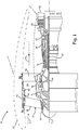
- FIG. 1 is a cross-sectional view of gas turbine engine 10, in a turbofan embodiment.
- gas turbine engine 10 includes fan 12, low pressure compressor (LPC) section 14, high pressure compressor (HPC) section 16, combustor 18, high pressure turbine (HPT) section 20, low pressure turbine (LPT) section 22, fan case 24, bypass duct 26, fan inlet cowl 28, exhaust nozzle 30, core flowpath F C , high pressure (HP) shaft 32, low pressure (LP) shaft 34, and structural guide vanes 36.
- Engine centerline CL denotes a central axis of gas turbine engine 10 in a direction parallel to the axial direction.
- Fan 12, LPC section 14, HPC section 16, combustor 18, HPT section 20, and LPT section 22 are arranged in flow series between fan inlet cowl 28 and exhaust nozzle 30 along engine centerline CL.
- fan 12 includes a plurality of fan blades 38 carried by fan hub 40.
- Basic operation of gas turbine engine 10 is well known and is not described in detail here.
- Gas turbine engine 10 can further include other components and features not specifically shown or discussed.
- Fan case 24 is disposed around fan 12 and can be formed from composite material. Fan blades 38 of fan 12 are circumferentially arranged in cascade around fan hub 40 and engine centerline CL. Fan 12 can be rotationally coupled, directly or indirectly, to LP shaft 34. In some embodiments, such as the embodiment of FIG. 1 , fan 12 is coupled to LP shaft 34 via a geared fan drive mechanism, providing independent fan speed control. As shown in FIG. 1 , fan 12 is forward-mounted and provides thrust by accelerating flow downstream through bypass duct 26. In operation of gas turbine engine 10, airflow F enters a flowpath defined by fan inlet cowl 28 and can divide into a core airflow and a bypass airflow, downstream of fan 12.
- the core airflow propagates along core flowpath F C through LPC section 14, HPC section 16, combustor 18, HPT section 20, and LPT section 22.
- the bypass airflow propagates along bypass flowpath F B through bypass duct 26.
- Structural guide vanes 36 can be disposed inside bypass duct 26 and extend between fan case 24 and a core case. As the bypass airflow flows from fan 12 into bypass duct 26, structural guide vanes 36 help de-swirl the bypass airflow into an axial direction substantially parallel to engine centerline CL. Structural guide vanes 36 also connect the core case to fan case 24 and center the core case and the engine core inside fan case 24.
- Fan case 24 is positioned generally aftward and downstream from fan inlet cowl 28, with both fan case 24 and fan inlet cowl 28 circumscribing the flowpath and fan blades 38.
- Fan containment liner 41 is positioned around the flowpath and fan blades 38 and at least partially radially inward from fan case 24.
- Liner assembly 42 is generally annular and is disposed aft of fan containment liner 41 and fan blades 38, and is disposed at least partially radially inward from fan case 24. Liner assembly 42 is discussed below in greater detail with respect to FIG. 2 .
- FIG. 2 is a cross-sectional view of an embodiment of liner assembly 42 of gas turbine engine 10.
- liner assembly 42 can include honeycomb core 44, impact resistant layer 46, and interior layer 48.
- Honeycomb core 44 can include first end 50, second end 52, first end 50 being disposed axially forward of second end 52.
- Honeycomb core 44 further includes forward segment 56, and aft segment 58.
- Forward segment 56 can include forward end 56a and aft end 56b.
- Aft segment 58 can include forward end 58a and aft end 58b.
- Interior layer 48 can include flowpath surface 62 and a plurality of perforations 64.
- Honeycomb core 44 is disposed radially inward of fan case 24 and aft of fan blades 38. Honeycomb core 44 can be connected to fan case 24 by a film adhesive. Honeycomb core 44 extends axially between first end 50 and second end 52. Honeycomb core 44 can be formed of aluminum or an aluminum alloy and includes a plurality of generally radially extending cells (for example, Helmoholtz resonators), the cells having a hexagonal geometry or other geometry that aides honeycomb core 44 in acoustically reducing noise within fan case 24. As illustrated, the cells of honeycomb core 44 can vary in the radial dimension, that is, cell thickness, between cells in the axial direction. As shown in the embodiment of FIG. 2 , axially adjacent cells of honeycomb core 44 can vary in thickness such that liner assembly 42 tapers in thickness in the downstream direction.
- Honeycomb core 44 can be axially segmented such that honeycomb core 44 includes forward segment 56 and aft segment 58.
- Aft segment 58 of honeycomb core 44 is disposed downstream of forward segment 56 and can directly abut forward segment 56.
- Forward end 56a of forward segment 56 can define first end 50 of honeycomb core 44 and aft end 56a is disposed axially between first end 50 and second end 52 of honeycomb core 44.
- Forward end 58a of aft segment 58 can be disposed adjacent aft end 56a of forward segment 56 and aft end 58b of aft segment 58 can define second end 52 of honeycomb core 44.
- forward segment 56 of honeycomb core 44 can have the same density as aft segment 58 of honeycomb core 44 such that all of honeycomb core 44 is substantially uniform in density. Segmenting honeycomb core 44 axially into forward segment 56 and aft segment 58 can increase the ease of manufacturing honeycomb core 44 and handling of honeycomb core 44 during the assembling process. This is because segmenting allows honeycomb core 44 to be manufactured, handled, and maneuvered in pieces.
- Forward segment 56 can taper in a downstream direction from forward end 56a to aft end 56b, and aft segment 58 can taper in a downstream direction from forward end 58a to aft end 58b. Tapering forward segment 56 and aft segment 58 helps to form and contour the flowpath within fan case 24.
- Each of the segments of the honeycomb core 44 can respectively have a substantially uniform density, that is, the cells have substantially equal sizing in the engine fore-aft direction, or cell length. Making the density of honeycomb core 44 substantially uniform helps reduce manufacturing complexity and cost of liner assembly 42.
- Impact resistant layer 46 is disposed at least partially radially inward from honeycomb core 44 and can be disposed on forward segment 56 of honeycomb core 44 such that impact resistant layer 46 axially extends from forward end 56a to aft end 56b of forward segment 56.
- Impact resistant layer 46 can be bonded to forward segment 56 by a film adhesive.
- a radial thickness of forward segment 56 can be selected to accommodate impact resistant layer 46 such that impact resistant layer 46 does not create a radially inner offset, that is a relatively raised shelf or ledge between forward segment 56 and aft segment 58 at forward end 58b.
- forward segment 56 can be less thick at aft end 56b than aft segment 58 at forward end 58b.
- Impact resistant layer 46 can be less thick radially than honeycomb core 44 and can be formed from layered plies of poly-paraphenylene terephthalamide (e.g., Kevlar ® material).
- Impact resistant layer 46 is disposed on forward segment 56 and aft of fan blades 38, impact resistant layer 46 is positioned where liner assembly 42 would generally be impacted by ice shed off of fan blades 38 during operation of gas turbine engine 10.
- Impact resistant layer 46 can be radially thicker than interior layer 48 (described below) and, in some embodiments, can be approximately three times thicker than interior layer 48.
- Interior layer 48 is disposed radially inward from honeycomb core 44 and impact resistant layer 46, and can be bonded to both impact resistant layer 46 and aft segment 58 of honeycomb core 44 by a film adhesive. Interior layer 48 can extend axially from first end 50 of honeycomb core 44 to second end 52 of honeycomb core 44 and can completely cover honeycomb core 44 and impact resistant layer 46. Interior layer 48 can also cover seam 59 between forward segment 56 and aft segment 58 and can define flowpath surface 62 extending relatively smoothly and uninterrupted between first end 50 and second end 52 of honeycomb core 44.
- Interior layer 48 is thinner than impact resistant layer 46.
- Interior layer 48 can be a covering or skin formed from layered plies of fiberglass. In the embodiment of FIG. 2 , interior layer 48 can formed from five layers of fiberglass plies while impact resistant layer 46 can be formed of fifteen layers of poly-paraphenylene terephthalamide (e.g., Kevlar ® material) plies. Together, interior layer 48 and impact resistant layer 46 help protect liner assembly 42 against ice shed off of fan blades 38 during operation of gas turbine engine 10.
- poly-paraphenylene terephthalamide e.g., Kevlar ® material
- a plurality of mutually axially offset perforations 64 can be formed in interior layer 48 between forward end 58a and aft end 58b of aft segment 58 of honeycomb core 44 (axially aligned with aft segment 58), so that the perforations 64 each communicate with one of the cells of honeycomb core 44 in aft segment 58.
- perforations 64 and honeycomb core 44 in aft segment 58 acoustically dampen noise generated within gas turbine engine 10 proximate fan 12.
- Interior layer 48 can remain free of perforations 64 upstream from forward end 58a of aft segment 58.
- honeycomb core 44 and impact resistant layer 46 can be segmented circumferentially into a plurality of panels 66.
- FIG. 3 is a cross-sectional view of liner assembly 42 taken along line A-A of FIG. 2 .
- liner assembly 42 can include panels 66 (shown in FIG. 3 as panel 66a and panel 66b) with seam 68 and gap 70.
- Interior layer 48 can also include edges 72.
- Panels 66 can be formed by segmenting honeycomb core 44 and impact resistant layer 46 circumferentially. As with axially segmenting honeycomb core 44 into forward segment 56 and aft segment 58, discussed above, circumferentially segmenting honeycomb core 44 and impact resistant layer 46 can increase ease of manufacturing liner assembly 42 and handling of liner assembly 42 during the assembling process. That is, segmenting allows honeycomb core 44 and impact resistant layer 46 to be manufactured, handled, and maneuvered in pieces.
- FIG. 3 shows, by way of example, first panel 66a disposed next to second panel 66b.
- Seam 68 can be disposed between honeycomb core 44 of first panel 66a and honeycomb core 44 of second panel 66b.
- Gap 70 can be disposed between impact resistant layer 46 on first panel 66a and impact resistant layer 46 on second panel 66b.
- Honeycomb core 44 can have a substantially uniform density circumferentially across panels 66.
- Interior layer 48 is disposed radially inward from panels 66 and can be bonded by a film adhesive to impact resistant layer 46 of each panel 66.
- Interior layer 48 is segmented circumferentially to form edges 72a and 72b. Edges 72 of each segment of interior layer 48 are circumferentially offset from seam 68 and gap 70 such that interior layer 48 extends over and covers seam 68 and gap 70. Because interior layer 48 extends over seam 68 and gap 70, interior layer 48 sufficiently protects seam 68 and gap 70 from impact damage without having to increase the density of honeycomb core 44 at seam 68. Edges 72 of each segment of interior layer 48 are overlapped and bonded to edges 72 of adjacent segments of interior layer 48 in a lap or shiplap joint to form a relatively smooth transition between segments of interior layer 48 so as to assist maintaining flowpath surface 62 relatively smooth.
- panels 66 can be formed by segmenting honeycomb core 44 apart from impact resistant layer 46.
- Impact resistant layer 46 can be segmented circumferentially into segments that differ in number and circumferential length than panels 66 of honeycomb core 44.
- gap 70 (or a splice) between segments of impact resistant layer 46 can be circumferentially misaligned from seam 68 between panels 66 of honeycomb core 44. Circumferentially misaligning gap 70 and seam 68 causes impact resistant layer 46 to cover seam 68 and reinforce honeycomb core 44 at seam 68.
- honeycomb core 44 can also include inserts of higher cell-density core circumferentially aligned with gaps 70 (or splices) between segments of impact resistant layer 46 to provide additional impact resistance at the location of gaps 70 (or the splices).
- Liner assembly 42 of the present invention can provide numerous advantages and benefits. Some examples of those advantages and benefits are as follows.
- Liner assembly 42 provides honeycomb core 44, impact resistant layer 46, and interior layer 48.
- Interior layer 48 defines relatively smooth and substantially uninterrupted flowpath surface 62 downstream from fan blades 38. Because flowpath surface 62 is relatively smooth and substantially uninterrupted, flowpath surface 62 increases the efficiency of gas turbine engine 10 by reducing flow losses downstream from fan 12.
- Impact resistant layer 46 and interior layer 48 together reinforce liner assembly 42 against impact from ice or other objects ingested by gas turbine engine 10.
- Honeycomb core 44 and interior layer 48 can assist in acoustically dampening noise generated by fan 12 downstream from impact resistant layer 46.
- Liner assembly 42 can also be relatively less complex than prior art liner assemblies because honeycomb core 44 can have a substantially uniform density and can be made up of fewer pieces.
- honeycomb core 44 as having a substantially uniform density
- the density of honeycomb core 44 can be varied circumferentially and/or axially without departing from the scope of the invention. Therefore, it is intended that the invention not be limited to the particular embodiment(s) disclosed, but that the invention will include all embodiments falling within the scope of the appended claims.
Landscapes
- Engineering & Computer Science (AREA)
- Chemical & Material Sciences (AREA)
- Combustion & Propulsion (AREA)
- Mechanical Engineering (AREA)
- General Engineering & Computer Science (AREA)
- Structures Of Non-Positive Displacement Pumps (AREA)
Claims (15)
- Ensemble de revêtement (42) pour le revêtement d'une turbine à gaz (10), l'ensemble de revêtement (42) comprenant :un noyau alvéolaire (44) ayant au moins deux segments axialement adjacents, y compris un segment avant (56) et un segment arrière (58) ;une couche résistante aux chocs (46) disposée radialement vers l'intérieur contre le segment alvéolaire avant (56) ; etune couche radialement intérieure (48), définissant un chemin d'écoulement sensiblement relativement ininterrompu sur au moins une partie de la couche résistante aux chocs (46) et du segment arrière (58), la couche intérieure (46) s'étendant radialement vers l'intérieur contre à la fois la couche résistante aux chocs (46) et le segment alvéolaire arrière (58) ;caractérisé en ce que :le noyau alvéolaire (44) et la couche résistante aux chocs (46) sont tous deux segmentés circonférentiellement en une pluralité de panneaux (66) agencés autour de l'axe de la turbine à gaz (10), et la couche intérieure (48) couvre une couture (68) entre les panneaux adjacents (66a, 66b) de la pluralité de panneaux (66) ;la couche intérieure (48) est segmentée circonférentiellement pour former des bords (72a, 72b), et les bords (72a, 72b) de chaque segment de la couche intérieure (48) sont décalés circonférentiellement par rapport à la couture (68) de telle sorte que la couche intérieure (48) s'étend sur la couture (68) et la couvre ; etles bords (72a, 72b) de chaque segment de la couche intérieure (48) sont superposés et collés aux bords (72a, 72b) de segments adjacents de la couche intérieure (48).
- Ensemble de revêtement (42) selon la revendication 1, dans lequel la couche résistante aux chocs (46) s'étend axialement d'une extrémité axialement avant (56a) du segment avant (56) vers une extrémité axialement arrière (56b) du segment avant (56) .
- Ensemble de revêtement (42) selon la revendication 2, dans lequel la couche intérieure (48) s'étend axialement de l'extrémité axialement avant (56a) du segment avant (56) vers une extrémité axialement arrière (58b) du segment arrière (58).
- Ensemble de revêtement selon la revendication 3, dans lequel une pluralité de perforations (64) sont formées dans la couche intérieure (48) en aval de l'extrémité axialement arrière (56b) du segment avant (56) du noyau alvéolaire (44).
- Ensemble de revêtement (42) selon une quelconque revendication précédente, dans lequel la couche résistante aux chocs (46) est formée à partir de plis superposés de poly(téréphtalamide de paraphénylène).
- Ensemble de revêtement (42) selon une quelconque revendication précédente, dans lequel la couche intérieure (48) est formée de fibre de verre.
- Ensemble de revêtement (42) selon une quelconque revendication précédente, dans lequel la couche résistante aux chocs (46) est plus épaisse que la couche intérieure (48).
- Ensemble de revêtement (42) selon la revendication 7, dans lequel la couche résistante aux chocs (46) est environ trois fois plus épaisse que la couche intérieure (48).
- Turbine à gaz (10) comprenant :une pluralité d'aubes de soufflante (38) agencées autour d'un axe de la turbine à gaz (10) ;un carter de soufflante (24) disposé autour de la pluralité d'aubes de soufflante (38) ; etun ensemble de revêtement (42) selon une quelconque revendication précédente disposé à l'intérieur du carter de soufflante (24) et à l'arrière des aubes de soufflante (38).
- Turbine à gaz (10) selon la revendication 9, dans laquelle le carter de soufflante (24) est composé de matériau composite.
- Turbine à gaz (10) selon la revendication 9 ou 10, dans laquelle la couche intérieure (48) définit une surface de chemin d'écoulement (62) en aval de la pluralité d'aubes de soufflante (38).
- Turbine à gaz selon l'une quelconque des revendications 9 à 11, dans laquelle le segment arrière (58) du noyau alvéolaire (44) vient en butée directement contre le segment avant (56) du noyau alvéolaire (44), le segment avant (56) du noyau alvéolaire (44) a la même densité cellulaire que le segment arrière (58) du noyau alvéolaire, et le segment avant s'amincit dans une direction aval d'une extrémité axialement avant (56a) du segment avant (56) vers une extrémité axialement arrière (56b) du segment avant (56).
- Turbine à gaz (10) selon la revendication 12, dans laquelle le segment arrière (58) s'amincit dans une direction aval d'une extrémité axialement avant (58a) du segment arrière (58) vers une extrémité axialement arrière (58b) du segment arrière (58), éventuellement dans laquelle l'extrémité axialement avant (58a) du segment arrière (58) est plus épaisse que l'extrémité axialement arrière (56b) du segment avant (56).
- Turbine à gaz (10) selon l'une quelconque des revendications 9 à 13, dans laquelle une épaisseur de l'ensemble de revêtement (42) s'amincit vers l'aval.
- Turbine à gaz (10) selon l'une quelconque des revendications 9 à 14, dans laquelle une pluralité de perforations (64) sont formées dans la couche intérieure (48) en aval du segment avant (56) du noyau alvéolaire (44) et la couche intérieure (48) est exempte de perforations en amont du segment arrière (58) du noyau alvéolaire (44).
Applications Claiming Priority (2)
| Application Number | Priority Date | Filing Date | Title |
|---|---|---|---|
| US201361919213P | 2013-12-20 | 2013-12-20 | |
| PCT/US2014/069073 WO2015094764A1 (fr) | 2013-12-20 | 2014-12-08 | Revêtement en couche de glace |
Publications (3)
| Publication Number | Publication Date |
|---|---|
| EP3084178A1 EP3084178A1 (fr) | 2016-10-26 |
| EP3084178A4 EP3084178A4 (fr) | 2016-12-28 |
| EP3084178B1 true EP3084178B1 (fr) | 2018-03-28 |
Family
ID=53403515
Family Applications (1)
| Application Number | Title | Priority Date | Filing Date |
|---|---|---|---|
| EP14871637.6A Active EP3084178B1 (fr) | 2013-12-20 | 2014-12-08 | Revêtement en couche de glace |
Country Status (3)
| Country | Link |
|---|---|
| US (1) | US20160273550A1 (fr) |
| EP (1) | EP3084178B1 (fr) |
| WO (1) | WO2015094764A1 (fr) |
Families Citing this family (5)
| Publication number | Priority date | Publication date | Assignee | Title |
|---|---|---|---|---|
| GB201417415D0 (en) * | 2014-10-02 | 2014-11-19 | Rolls Royce Plc | Fan track liner assembly |
| GB201805006D0 (en) * | 2018-03-28 | 2018-05-09 | Rolls Royce Plc | A containment assembly |
| US20200011203A1 (en) * | 2018-07-06 | 2020-01-09 | General Electric Company | Blade containment structure |
| US11047316B2 (en) * | 2019-04-09 | 2021-06-29 | Pratt & Whitney Canada Corp. | Method of ice removal by inducing sudden variation of rotor speed in a gas turbine engine |
| US11788549B2 (en) * | 2021-10-04 | 2023-10-17 | General Electric Company | Turbofan blade blocking apparatus |
Family Cites Families (8)
| Publication number | Priority date | Publication date | Assignee | Title |
|---|---|---|---|---|
| US4534698A (en) * | 1983-04-25 | 1985-08-13 | General Electric Company | Blade containment structure |
| CA2042198A1 (fr) * | 1990-06-18 | 1991-12-19 | Stephen C. Mitchell | Ecran protecteur contre les projectiles |
| US5160248A (en) | 1991-02-25 | 1992-11-03 | General Electric Company | Fan case liner for a gas turbine engine with improved foreign body impact resistance |
| US5344280A (en) * | 1993-05-05 | 1994-09-06 | General Electric Company | Impact resistant fan case liner |
| FR2847304B1 (fr) * | 2002-11-18 | 2005-07-01 | Airbus France | Nacelle de reacteur d'aeronef a attenuation acoustique |
| US8672609B2 (en) * | 2009-08-31 | 2014-03-18 | United Technologies Corporation | Composite fan containment case assembly |
| US9249681B2 (en) * | 2012-01-31 | 2016-02-02 | United Technologies Corporation | Fan case rub system |
| US9200531B2 (en) | 2012-01-31 | 2015-12-01 | United Technologies Corporation | Fan case rub system, components, and their manufacture |
-
2014
- 2014-12-08 US US15/037,770 patent/US20160273550A1/en not_active Abandoned
- 2014-12-08 EP EP14871637.6A patent/EP3084178B1/fr active Active
- 2014-12-08 WO PCT/US2014/069073 patent/WO2015094764A1/fr not_active Ceased
Non-Patent Citations (1)
| Title |
|---|
| None * |
Also Published As
| Publication number | Publication date |
|---|---|
| WO2015094764A1 (fr) | 2015-06-25 |
| EP3084178A4 (fr) | 2016-12-28 |
| US20160273550A1 (en) | 2016-09-22 |
| EP3084178A1 (fr) | 2016-10-26 |
Similar Documents
| Publication | Publication Date | Title |
|---|---|---|
| CN109415940B (zh) | 用于复合风扇叶片的金属前缘 | |
| EP3441565B1 (fr) | Aube de soufflante comportant une poche d'extrémité et procédé | |
| EP2336500B1 (fr) | Méthode pour fabriquer un dispositif d'admission d'un moteur-fusée | |
| EP2930317B1 (fr) | Entrée d'une turbine à gaz | |
| EP2855849B1 (fr) | Système de cache d'aile portante | |
| EP2812558B1 (fr) | Moteur à turbine à gaz à générateur de gaz et unité de propulsion distincts | |
| EP2932052B1 (fr) | Boîtier de confinement de soufflante doté d'un chemisage conforme thermiquement | |
| US20080159856A1 (en) | Guide vane and method of fabricating the same | |
| EP1942253A2 (fr) | Aube de guidage et son procédé de fabrication | |
| EP1908920A2 (fr) | Aube fixe et turbine à gaz comprenant plusieurs de ces aubes | |
| EP2366871B1 (fr) | Procédé et appareil pour conduit d'aube de sortie structurelle | |
| EP2952696B1 (fr) | Ensemble turboréacteur à double flux avec cartouche de revêtement pour le carter de soufflante | |
| US20150345320A1 (en) | Fan case with auxetic liner | |
| EP2604811B1 (fr) | Carter de soufflante à absorption d'énergie pour un moteur à turbine à gaz | |
| CA2602319A1 (fr) | Systeme de retenue des aubes pour turbine a gaz | |
| US20160273550A1 (en) | Layered ice liner | |
| EP3106289B1 (fr) | Anneau de confinement de boîtier de ventilateur métallique co-moulé | |
| US12209506B2 (en) | Composite fan case containment hook and improved forward debris capture | |
| WO2014197053A2 (fr) | Cartouche de revêtement insonorisant thermiquement conformable pour un moteur à turbine à gaz | |
| EP4223980B1 (fr) | Ensemble rotor à plateformes structurelles pour moteurs à turbine à gaz | |
| EP2915742B2 (fr) | Moteur à turbine à gaz avec cône renforcé | |
| US20240288002A1 (en) | Turbomachine and method of assembly | |
| US12305524B1 (en) | Containment ring for gas turbine engine | |
| US20240301889A1 (en) | Turbomachine and method of assembly | |
| US20240288003A1 (en) | Turbomachine and method of assembly |
Legal Events
| Date | Code | Title | Description |
|---|---|---|---|
| PUAI | Public reference made under article 153(3) epc to a published international application that has entered the european phase |
Free format text: ORIGINAL CODE: 0009012 |
|
| 17P | Request for examination filed |
Effective date: 20160711 |
|
| AK | Designated contracting states |
Kind code of ref document: A1 Designated state(s): AL AT BE BG CH CY CZ DE DK EE ES FI FR GB GR HR HU IE IS IT LI LT LU LV MC MK MT NL NO PL PT RO RS SE SI SK SM TR |
|
| AX | Request for extension of the european patent |
Extension state: BA ME |
|
| A4 | Supplementary search report drawn up and despatched |
Effective date: 20161130 |
|
| RIC1 | Information provided on ipc code assigned before grant |
Ipc: F02C 7/05 20060101AFI20161124BHEP |
|
| DAX | Request for extension of the european patent (deleted) | ||
| GRAP | Despatch of communication of intention to grant a patent |
Free format text: ORIGINAL CODE: EPIDOSNIGR1 |
|
| STAA | Information on the status of an ep patent application or granted ep patent |
Free format text: STATUS: GRANT OF PATENT IS INTENDED |
|
| INTG | Intention to grant announced |
Effective date: 20170831 |
|
| GRAJ | Information related to disapproval of communication of intention to grant by the applicant or resumption of examination proceedings by the epo deleted |
Free format text: ORIGINAL CODE: EPIDOSDIGR1 |
|
| STAA | Information on the status of an ep patent application or granted ep patent |
Free format text: STATUS: REQUEST FOR EXAMINATION WAS MADE |
|
| GRAR | Information related to intention to grant a patent recorded |
Free format text: ORIGINAL CODE: EPIDOSNIGR71 |
|
| GRAS | Grant fee paid |
Free format text: ORIGINAL CODE: EPIDOSNIGR3 |
|
| INTC | Intention to grant announced (deleted) | ||
| STAA | Information on the status of an ep patent application or granted ep patent |
Free format text: STATUS: GRANT OF PATENT IS INTENDED |
|
| GRAA | (expected) grant |
Free format text: ORIGINAL CODE: 0009210 |
|
| STAA | Information on the status of an ep patent application or granted ep patent |
Free format text: STATUS: THE PATENT HAS BEEN GRANTED |
|
| AK | Designated contracting states |
Kind code of ref document: B1 Designated state(s): AL AT BE BG CH CY CZ DE DK EE ES FI FR GB GR HR HU IE IS IT LI LT LU LV MC MK MT NL NO PL PT RO RS SE SI SK SM TR |
|
| INTG | Intention to grant announced |
Effective date: 20180220 |
|
| REG | Reference to a national code |
Ref country code: GB Ref legal event code: FG4D |
|
| REG | Reference to a national code |
Ref country code: CH Ref legal event code: EP |
|
| REG | Reference to a national code |
Ref country code: AT Ref legal event code: REF Ref document number: 983658 Country of ref document: AT Kind code of ref document: T Effective date: 20180415 |
|
| REG | Reference to a national code |
Ref country code: IE Ref legal event code: FG4D |
|
| REG | Reference to a national code |
Ref country code: DE Ref legal event code: R096 Ref document number: 602014023168 Country of ref document: DE |
|
| PG25 | Lapsed in a contracting state [announced via postgrant information from national office to epo] |
Ref country code: LT Free format text: LAPSE BECAUSE OF FAILURE TO SUBMIT A TRANSLATION OF THE DESCRIPTION OR TO PAY THE FEE WITHIN THE PRESCRIBED TIME-LIMIT Effective date: 20180328 Ref country code: FI Free format text: LAPSE BECAUSE OF FAILURE TO SUBMIT A TRANSLATION OF THE DESCRIPTION OR TO PAY THE FEE WITHIN THE PRESCRIBED TIME-LIMIT Effective date: 20180328 Ref country code: HR Free format text: LAPSE BECAUSE OF FAILURE TO SUBMIT A TRANSLATION OF THE DESCRIPTION OR TO PAY THE FEE WITHIN THE PRESCRIBED TIME-LIMIT Effective date: 20180328 Ref country code: NO Free format text: LAPSE BECAUSE OF FAILURE TO SUBMIT A TRANSLATION OF THE DESCRIPTION OR TO PAY THE FEE WITHIN THE PRESCRIBED TIME-LIMIT Effective date: 20180628 |
|
| REG | Reference to a national code |
Ref country code: NL Ref legal event code: MP Effective date: 20180328 |
|
| REG | Reference to a national code |
Ref country code: LT Ref legal event code: MG4D |
|
| PG25 | Lapsed in a contracting state [announced via postgrant information from national office to epo] |
Ref country code: BG Free format text: LAPSE BECAUSE OF FAILURE TO SUBMIT A TRANSLATION OF THE DESCRIPTION OR TO PAY THE FEE WITHIN THE PRESCRIBED TIME-LIMIT Effective date: 20180628 Ref country code: RS Free format text: LAPSE BECAUSE OF FAILURE TO SUBMIT A TRANSLATION OF THE DESCRIPTION OR TO PAY THE FEE WITHIN THE PRESCRIBED TIME-LIMIT Effective date: 20180328 Ref country code: LV Free format text: LAPSE BECAUSE OF FAILURE TO SUBMIT A TRANSLATION OF THE DESCRIPTION OR TO PAY THE FEE WITHIN THE PRESCRIBED TIME-LIMIT Effective date: 20180328 Ref country code: SE Free format text: LAPSE BECAUSE OF FAILURE TO SUBMIT A TRANSLATION OF THE DESCRIPTION OR TO PAY THE FEE WITHIN THE PRESCRIBED TIME-LIMIT Effective date: 20180328 Ref country code: GR Free format text: LAPSE BECAUSE OF FAILURE TO SUBMIT A TRANSLATION OF THE DESCRIPTION OR TO PAY THE FEE WITHIN THE PRESCRIBED TIME-LIMIT Effective date: 20180629 |
|
| PG25 | Lapsed in a contracting state [announced via postgrant information from national office to epo] |
Ref country code: RO Free format text: LAPSE BECAUSE OF FAILURE TO SUBMIT A TRANSLATION OF THE DESCRIPTION OR TO PAY THE FEE WITHIN THE PRESCRIBED TIME-LIMIT Effective date: 20180328 Ref country code: IT Free format text: LAPSE BECAUSE OF FAILURE TO SUBMIT A TRANSLATION OF THE DESCRIPTION OR TO PAY THE FEE WITHIN THE PRESCRIBED TIME-LIMIT Effective date: 20180328 Ref country code: PL Free format text: LAPSE BECAUSE OF FAILURE TO SUBMIT A TRANSLATION OF THE DESCRIPTION OR TO PAY THE FEE WITHIN THE PRESCRIBED TIME-LIMIT Effective date: 20180328 Ref country code: ES Free format text: LAPSE BECAUSE OF FAILURE TO SUBMIT A TRANSLATION OF THE DESCRIPTION OR TO PAY THE FEE WITHIN THE PRESCRIBED TIME-LIMIT Effective date: 20180328 Ref country code: NL Free format text: LAPSE BECAUSE OF FAILURE TO SUBMIT A TRANSLATION OF THE DESCRIPTION OR TO PAY THE FEE WITHIN THE PRESCRIBED TIME-LIMIT Effective date: 20180328 Ref country code: AL Free format text: LAPSE BECAUSE OF FAILURE TO SUBMIT A TRANSLATION OF THE DESCRIPTION OR TO PAY THE FEE WITHIN THE PRESCRIBED TIME-LIMIT Effective date: 20180328 Ref country code: EE Free format text: LAPSE BECAUSE OF FAILURE TO SUBMIT A TRANSLATION OF THE DESCRIPTION OR TO PAY THE FEE WITHIN THE PRESCRIBED TIME-LIMIT Effective date: 20180328 |
|
| PG25 | Lapsed in a contracting state [announced via postgrant information from national office to epo] |
Ref country code: SM Free format text: LAPSE BECAUSE OF FAILURE TO SUBMIT A TRANSLATION OF THE DESCRIPTION OR TO PAY THE FEE WITHIN THE PRESCRIBED TIME-LIMIT Effective date: 20180328 Ref country code: CZ Free format text: LAPSE BECAUSE OF FAILURE TO SUBMIT A TRANSLATION OF THE DESCRIPTION OR TO PAY THE FEE WITHIN THE PRESCRIBED TIME-LIMIT Effective date: 20180328 Ref country code: SK Free format text: LAPSE BECAUSE OF FAILURE TO SUBMIT A TRANSLATION OF THE DESCRIPTION OR TO PAY THE FEE WITHIN THE PRESCRIBED TIME-LIMIT Effective date: 20180328 |
|
| REG | Reference to a national code |
Ref country code: AT Ref legal event code: MK05 Ref document number: 983658 Country of ref document: AT Kind code of ref document: T Effective date: 20180328 |
|
| PG25 | Lapsed in a contracting state [announced via postgrant information from national office to epo] |
Ref country code: PT Free format text: LAPSE BECAUSE OF FAILURE TO SUBMIT A TRANSLATION OF THE DESCRIPTION OR TO PAY THE FEE WITHIN THE PRESCRIBED TIME-LIMIT Effective date: 20180730 |
|
| REG | Reference to a national code |
Ref country code: DE Ref legal event code: R097 Ref document number: 602014023168 Country of ref document: DE |
|
| PG25 | Lapsed in a contracting state [announced via postgrant information from national office to epo] |
Ref country code: DK Free format text: LAPSE BECAUSE OF FAILURE TO SUBMIT A TRANSLATION OF THE DESCRIPTION OR TO PAY THE FEE WITHIN THE PRESCRIBED TIME-LIMIT Effective date: 20180328 Ref country code: AT Free format text: LAPSE BECAUSE OF FAILURE TO SUBMIT A TRANSLATION OF THE DESCRIPTION OR TO PAY THE FEE WITHIN THE PRESCRIBED TIME-LIMIT Effective date: 20180328 |
|
| PLBE | No opposition filed within time limit |
Free format text: ORIGINAL CODE: 0009261 |
|
| STAA | Information on the status of an ep patent application or granted ep patent |
Free format text: STATUS: NO OPPOSITION FILED WITHIN TIME LIMIT |
|
| 26N | No opposition filed |
Effective date: 20190103 |
|
| PG25 | Lapsed in a contracting state [announced via postgrant information from national office to epo] |
Ref country code: SI Free format text: LAPSE BECAUSE OF FAILURE TO SUBMIT A TRANSLATION OF THE DESCRIPTION OR TO PAY THE FEE WITHIN THE PRESCRIBED TIME-LIMIT Effective date: 20180328 |
|
| REG | Reference to a national code |
Ref country code: CH Ref legal event code: PL |
|
| PG25 | Lapsed in a contracting state [announced via postgrant information from national office to epo] |
Ref country code: LU Free format text: LAPSE BECAUSE OF NON-PAYMENT OF DUE FEES Effective date: 20181208 Ref country code: MC Free format text: LAPSE BECAUSE OF FAILURE TO SUBMIT A TRANSLATION OF THE DESCRIPTION OR TO PAY THE FEE WITHIN THE PRESCRIBED TIME-LIMIT Effective date: 20180328 |
|
| REG | Reference to a national code |
Ref country code: IE Ref legal event code: MM4A |
|
| REG | Reference to a national code |
Ref country code: BE Ref legal event code: MM Effective date: 20181231 |
|
| PG25 | Lapsed in a contracting state [announced via postgrant information from national office to epo] |
Ref country code: IE Free format text: LAPSE BECAUSE OF NON-PAYMENT OF DUE FEES Effective date: 20181208 |
|
| PG25 | Lapsed in a contracting state [announced via postgrant information from national office to epo] |
Ref country code: BE Free format text: LAPSE BECAUSE OF NON-PAYMENT OF DUE FEES Effective date: 20181231 |
|
| PG25 | Lapsed in a contracting state [announced via postgrant information from national office to epo] |
Ref country code: LI Free format text: LAPSE BECAUSE OF NON-PAYMENT OF DUE FEES Effective date: 20181231 Ref country code: CH Free format text: LAPSE BECAUSE OF NON-PAYMENT OF DUE FEES Effective date: 20181231 |
|
| PG25 | Lapsed in a contracting state [announced via postgrant information from national office to epo] |
Ref country code: MT Free format text: LAPSE BECAUSE OF NON-PAYMENT OF DUE FEES Effective date: 20181208 |
|
| PG25 | Lapsed in a contracting state [announced via postgrant information from national office to epo] |
Ref country code: TR Free format text: LAPSE BECAUSE OF FAILURE TO SUBMIT A TRANSLATION OF THE DESCRIPTION OR TO PAY THE FEE WITHIN THE PRESCRIBED TIME-LIMIT Effective date: 20180328 |
|
| PG25 | Lapsed in a contracting state [announced via postgrant information from national office to epo] |
Ref country code: CY Free format text: LAPSE BECAUSE OF FAILURE TO SUBMIT A TRANSLATION OF THE DESCRIPTION OR TO PAY THE FEE WITHIN THE PRESCRIBED TIME-LIMIT Effective date: 20180328 Ref country code: MK Free format text: LAPSE BECAUSE OF NON-PAYMENT OF DUE FEES Effective date: 20180328 Ref country code: HU Free format text: LAPSE BECAUSE OF FAILURE TO SUBMIT A TRANSLATION OF THE DESCRIPTION OR TO PAY THE FEE WITHIN THE PRESCRIBED TIME-LIMIT; INVALID AB INITIO Effective date: 20141208 |
|
| PG25 | Lapsed in a contracting state [announced via postgrant information from national office to epo] |
Ref country code: IS Free format text: LAPSE BECAUSE OF FAILURE TO SUBMIT A TRANSLATION OF THE DESCRIPTION OR TO PAY THE FEE WITHIN THE PRESCRIBED TIME-LIMIT Effective date: 20180728 |
|
| REG | Reference to a national code |
Ref country code: DE Ref legal event code: R081 Ref document number: 602014023168 Country of ref document: DE Owner name: RAYTHEON TECHNOLOGIES CORPORATION (N.D.GES.D.S, US Free format text: FORMER OWNER: UNITED TECHNOLOGIES CORPORATION, FARMINGTON, CONN., US Ref country code: DE Ref legal event code: R081 Ref document number: 602014023168 Country of ref document: DE Owner name: RTX CORPORATION (N.D.GES.D. STAATES DELAWARE),, US Free format text: FORMER OWNER: UNITED TECHNOLOGIES CORPORATION, FARMINGTON, CONN., US |
|
| P01 | Opt-out of the competence of the unified patent court (upc) registered |
Effective date: 20230520 |
|
| REG | Reference to a national code |
Ref country code: DE Ref legal event code: R081 Ref document number: 602014023168 Country of ref document: DE Owner name: RTX CORPORATION (N.D.GES.D. STAATES DELAWARE),, US Free format text: FORMER OWNER: RAYTHEON TECHNOLOGIES CORPORATION (N.D.GES.D.STAATES DELAWARE), ARLINGTON, VA, US |
|
| PGFP | Annual fee paid to national office [announced via postgrant information from national office to epo] |
Ref country code: DE Payment date: 20251126 Year of fee payment: 12 |
|
| PGFP | Annual fee paid to national office [announced via postgrant information from national office to epo] |
Ref country code: GB Payment date: 20251120 Year of fee payment: 12 |
|
| PGFP | Annual fee paid to national office [announced via postgrant information from national office to epo] |
Ref country code: FR Payment date: 20251119 Year of fee payment: 12 |