EP3084543B1 - Détection d'obstacle pour une tondeuse robotisée - Google Patents
Détection d'obstacle pour une tondeuse robotisée Download PDFInfo
- Publication number
- EP3084543B1 EP3084543B1 EP13899964.4A EP13899964A EP3084543B1 EP 3084543 B1 EP3084543 B1 EP 3084543B1 EP 13899964 A EP13899964 A EP 13899964A EP 3084543 B1 EP3084543 B1 EP 3084543B1
- Authority
- EP
- European Patent Office
- Prior art keywords
- beacon
- robotic lawnmower
- marker
- beacon marker
- work tool
- Prior art date
- Legal status (The legal status is an assumption and is not a legal conclusion. Google has not performed a legal analysis and makes no representation as to the accuracy of the status listed.)
- Active
Links
Images

Classifications
-
- G—PHYSICS
- G05—CONTROLLING; REGULATING
- G05D—SYSTEMS FOR CONTROLLING OR REGULATING NON-ELECTRIC VARIABLES
- G05D1/00—Control of position, course, altitude or attitude of land, water, air or space vehicles, e.g. using automatic pilots
- G05D1/02—Control of position or course in two dimensions
- G05D1/021—Control of position or course in two dimensions specially adapted to land vehicles
- G05D1/0276—Control of position or course in two dimensions specially adapted to land vehicles using signals provided by a source external to the vehicle
- G05D1/028—Control of position or course in two dimensions specially adapted to land vehicles using signals provided by a source external to the vehicle using a RF signal
-
- A—HUMAN NECESSITIES
- A01—AGRICULTURE; FORESTRY; ANIMAL HUSBANDRY; HUNTING; TRAPPING; FISHING
- A01D—HARVESTING; MOWING
- A01D34/00—Mowers; Mowing apparatus of harvesters
- A01D34/006—Control or measuring arrangements
- A01D34/008—Control or measuring arrangements for automated or remotely controlled operation
-
- A—HUMAN NECESSITIES
- A01—AGRICULTURE; FORESTRY; ANIMAL HUSBANDRY; HUNTING; TRAPPING; FISHING
- A01D—HARVESTING; MOWING
- A01D75/00—Accessories for harvesters or mowers
- A01D75/18—Safety devices for parts of the machines
- A01D75/185—Avoiding collisions with obstacles
-
- B—PERFORMING OPERATIONS; TRANSPORTING
- B60—VEHICLES IN GENERAL
- B60L—PROPULSION OF ELECTRICALLY-PROPELLED VEHICLES; SUPPLYING ELECTRIC POWER FOR AUXILIARY EQUIPMENT OF ELECTRICALLY-PROPELLED VEHICLES; ELECTRODYNAMIC BRAKE SYSTEMS FOR VEHICLES IN GENERAL; MAGNETIC SUSPENSION OR LEVITATION FOR VEHICLES; MONITORING OPERATING VARIABLES OF ELECTRICALLY-PROPELLED VEHICLES; ELECTRIC SAFETY DEVICES FOR ELECTRICALLY-PROPELLED VEHICLES
- B60L1/00—Supplying electric power to auxiliary equipment of vehicles
- B60L1/003—Supplying electric power to auxiliary equipment of vehicles to auxiliary motors, e.g. for pumps, compressors
-
- B—PERFORMING OPERATIONS; TRANSPORTING
- B60—VEHICLES IN GENERAL
- B60L—PROPULSION OF ELECTRICALLY-PROPELLED VEHICLES; SUPPLYING ELECTRIC POWER FOR AUXILIARY EQUIPMENT OF ELECTRICALLY-PROPELLED VEHICLES; ELECTRODYNAMIC BRAKE SYSTEMS FOR VEHICLES IN GENERAL; MAGNETIC SUSPENSION OR LEVITATION FOR VEHICLES; MONITORING OPERATING VARIABLES OF ELECTRICALLY-PROPELLED VEHICLES; ELECTRIC SAFETY DEVICES FOR ELECTRICALLY-PROPELLED VEHICLES
- B60L15/00—Methods, circuits, or devices for controlling the traction-motor speed of electrically-propelled vehicles
- B60L15/20—Methods, circuits, or devices for controlling the traction-motor speed of electrically-propelled vehicles for control of the vehicle or its driving motor to achieve a desired performance, e.g. speed, torque, programmed variation of speed
- B60L15/2036—Electric differentials, e.g. for supporting steering vehicles
-
- B—PERFORMING OPERATIONS; TRANSPORTING
- B60—VEHICLES IN GENERAL
- B60L—PROPULSION OF ELECTRICALLY-PROPELLED VEHICLES; SUPPLYING ELECTRIC POWER FOR AUXILIARY EQUIPMENT OF ELECTRICALLY-PROPELLED VEHICLES; ELECTRODYNAMIC BRAKE SYSTEMS FOR VEHICLES IN GENERAL; MAGNETIC SUSPENSION OR LEVITATION FOR VEHICLES; MONITORING OPERATING VARIABLES OF ELECTRICALLY-PROPELLED VEHICLES; ELECTRIC SAFETY DEVICES FOR ELECTRICALLY-PROPELLED VEHICLES
- B60L50/00—Electric propulsion with power supplied within the vehicle
- B60L50/10—Electric propulsion with power supplied within the vehicle using propulsion power supplied by engine-driven generators, e.g. generators driven by combustion engines
- B60L50/16—Electric propulsion with power supplied within the vehicle using propulsion power supplied by engine-driven generators, e.g. generators driven by combustion engines with provision for separate direct mechanical propulsion
-
- B—PERFORMING OPERATIONS; TRANSPORTING
- B60—VEHICLES IN GENERAL
- B60L—PROPULSION OF ELECTRICALLY-PROPELLED VEHICLES; SUPPLYING ELECTRIC POWER FOR AUXILIARY EQUIPMENT OF ELECTRICALLY-PROPELLED VEHICLES; ELECTRODYNAMIC BRAKE SYSTEMS FOR VEHICLES IN GENERAL; MAGNETIC SUSPENSION OR LEVITATION FOR VEHICLES; MONITORING OPERATING VARIABLES OF ELECTRICALLY-PROPELLED VEHICLES; ELECTRIC SAFETY DEVICES FOR ELECTRICALLY-PROPELLED VEHICLES
- B60L50/00—Electric propulsion with power supplied within the vehicle
- B60L50/50—Electric propulsion with power supplied within the vehicle using propulsion power supplied by batteries or fuel cells
- B60L50/52—Electric propulsion with power supplied within the vehicle using propulsion power supplied by batteries or fuel cells characterised by DC-motors
-
- B—PERFORMING OPERATIONS; TRANSPORTING
- B60—VEHICLES IN GENERAL
- B60L—PROPULSION OF ELECTRICALLY-PROPELLED VEHICLES; SUPPLYING ELECTRIC POWER FOR AUXILIARY EQUIPMENT OF ELECTRICALLY-PROPELLED VEHICLES; ELECTRODYNAMIC BRAKE SYSTEMS FOR VEHICLES IN GENERAL; MAGNETIC SUSPENSION OR LEVITATION FOR VEHICLES; MONITORING OPERATING VARIABLES OF ELECTRICALLY-PROPELLED VEHICLES; ELECTRIC SAFETY DEVICES FOR ELECTRICALLY-PROPELLED VEHICLES
- B60L53/00—Methods of charging batteries, specially adapted for electric vehicles; Charging stations or on-board charging equipment therefor; Exchange of energy storage elements in electric vehicles
- B60L53/10—Methods of charging batteries, specially adapted for electric vehicles; Charging stations or on-board charging equipment therefor; Exchange of energy storage elements in electric vehicles characterised by the energy transfer between the charging station and the vehicle
- B60L53/14—Conductive energy transfer
-
- B—PERFORMING OPERATIONS; TRANSPORTING
- B60—VEHICLES IN GENERAL
- B60L—PROPULSION OF ELECTRICALLY-PROPELLED VEHICLES; SUPPLYING ELECTRIC POWER FOR AUXILIARY EQUIPMENT OF ELECTRICALLY-PROPELLED VEHICLES; ELECTRODYNAMIC BRAKE SYSTEMS FOR VEHICLES IN GENERAL; MAGNETIC SUSPENSION OR LEVITATION FOR VEHICLES; MONITORING OPERATING VARIABLES OF ELECTRICALLY-PROPELLED VEHICLES; ELECTRIC SAFETY DEVICES FOR ELECTRICALLY-PROPELLED VEHICLES
- B60L53/00—Methods of charging batteries, specially adapted for electric vehicles; Charging stations or on-board charging equipment therefor; Exchange of energy storage elements in electric vehicles
- B60L53/30—Constructional details of charging stations
-
- B—PERFORMING OPERATIONS; TRANSPORTING
- B60—VEHICLES IN GENERAL
- B60L—PROPULSION OF ELECTRICALLY-PROPELLED VEHICLES; SUPPLYING ELECTRIC POWER FOR AUXILIARY EQUIPMENT OF ELECTRICALLY-PROPELLED VEHICLES; ELECTRODYNAMIC BRAKE SYSTEMS FOR VEHICLES IN GENERAL; MAGNETIC SUSPENSION OR LEVITATION FOR VEHICLES; MONITORING OPERATING VARIABLES OF ELECTRICALLY-PROPELLED VEHICLES; ELECTRIC SAFETY DEVICES FOR ELECTRICALLY-PROPELLED VEHICLES
- B60L8/00—Electric propulsion with power supply from forces of nature, e.g. sun or wind
- B60L8/003—Converting light into electric energy, e.g. by using photo-voltaic systems
-
- G—PHYSICS
- G05—CONTROLLING; REGULATING
- G05D—SYSTEMS FOR CONTROLLING OR REGULATING NON-ELECTRIC VARIABLES
- G05D1/00—Control of position, course, altitude or attitude of land, water, air or space vehicles, e.g. using automatic pilots
- G05D1/02—Control of position or course in two dimensions
- G05D1/021—Control of position or course in two dimensions specially adapted to land vehicles
- G05D1/0255—Control of position or course in two dimensions specially adapted to land vehicles using acoustic signals, e.g. ultra-sonic singals
-
- A—HUMAN NECESSITIES
- A47—FURNITURE; DOMESTIC ARTICLES OR APPLIANCES; COFFEE MILLS; SPICE MILLS; SUCTION CLEANERS IN GENERAL
- A47L—DOMESTIC WASHING OR CLEANING; SUCTION CLEANERS IN GENERAL
- A47L2201/00—Robotic cleaning machines, i.e. with automatic control of the travelling movement or the cleaning operation
- A47L2201/04—Automatic control of the travelling movement; Automatic obstacle detection
-
- B—PERFORMING OPERATIONS; TRANSPORTING
- B60—VEHICLES IN GENERAL
- B60L—PROPULSION OF ELECTRICALLY-PROPELLED VEHICLES; SUPPLYING ELECTRIC POWER FOR AUXILIARY EQUIPMENT OF ELECTRICALLY-PROPELLED VEHICLES; ELECTRODYNAMIC BRAKE SYSTEMS FOR VEHICLES IN GENERAL; MAGNETIC SUSPENSION OR LEVITATION FOR VEHICLES; MONITORING OPERATING VARIABLES OF ELECTRICALLY-PROPELLED VEHICLES; ELECTRIC SAFETY DEVICES FOR ELECTRICALLY-PROPELLED VEHICLES
- B60L2200/00—Type of vehicles
- B60L2200/40—Working vehicles
-
- B—PERFORMING OPERATIONS; TRANSPORTING
- B60—VEHICLES IN GENERAL
- B60L—PROPULSION OF ELECTRICALLY-PROPELLED VEHICLES; SUPPLYING ELECTRIC POWER FOR AUXILIARY EQUIPMENT OF ELECTRICALLY-PROPELLED VEHICLES; ELECTRODYNAMIC BRAKE SYSTEMS FOR VEHICLES IN GENERAL; MAGNETIC SUSPENSION OR LEVITATION FOR VEHICLES; MONITORING OPERATING VARIABLES OF ELECTRICALLY-PROPELLED VEHICLES; ELECTRIC SAFETY DEVICES FOR ELECTRICALLY-PROPELLED VEHICLES
- B60L2220/00—Electrical machine types; Structures or applications thereof
- B60L2220/40—Electrical machine applications
- B60L2220/46—Wheel motors, i.e. motor connected to only one wheel
-
- B—PERFORMING OPERATIONS; TRANSPORTING
- B60—VEHICLES IN GENERAL
- B60L—PROPULSION OF ELECTRICALLY-PROPELLED VEHICLES; SUPPLYING ELECTRIC POWER FOR AUXILIARY EQUIPMENT OF ELECTRICALLY-PROPELLED VEHICLES; ELECTRODYNAMIC BRAKE SYSTEMS FOR VEHICLES IN GENERAL; MAGNETIC SUSPENSION OR LEVITATION FOR VEHICLES; MONITORING OPERATING VARIABLES OF ELECTRICALLY-PROPELLED VEHICLES; ELECTRIC SAFETY DEVICES FOR ELECTRICALLY-PROPELLED VEHICLES
- B60L2240/00—Control parameters of input or output; Target parameters
- B60L2240/40—Drive Train control parameters
- B60L2240/42—Drive Train control parameters related to electric machines
- B60L2240/423—Torque
-
- B—PERFORMING OPERATIONS; TRANSPORTING
- B60—VEHICLES IN GENERAL
- B60L—PROPULSION OF ELECTRICALLY-PROPELLED VEHICLES; SUPPLYING ELECTRIC POWER FOR AUXILIARY EQUIPMENT OF ELECTRICALLY-PROPELLED VEHICLES; ELECTRODYNAMIC BRAKE SYSTEMS FOR VEHICLES IN GENERAL; MAGNETIC SUSPENSION OR LEVITATION FOR VEHICLES; MONITORING OPERATING VARIABLES OF ELECTRICALLY-PROPELLED VEHICLES; ELECTRIC SAFETY DEVICES FOR ELECTRICALLY-PROPELLED VEHICLES
- B60L2240/00—Control parameters of input or output; Target parameters
- B60L2240/60—Navigation input
- B60L2240/62—Vehicle position
-
- B—PERFORMING OPERATIONS; TRANSPORTING
- B60—VEHICLES IN GENERAL
- B60L—PROPULSION OF ELECTRICALLY-PROPELLED VEHICLES; SUPPLYING ELECTRIC POWER FOR AUXILIARY EQUIPMENT OF ELECTRICALLY-PROPELLED VEHICLES; ELECTRODYNAMIC BRAKE SYSTEMS FOR VEHICLES IN GENERAL; MAGNETIC SUSPENSION OR LEVITATION FOR VEHICLES; MONITORING OPERATING VARIABLES OF ELECTRICALLY-PROPELLED VEHICLES; ELECTRIC SAFETY DEVICES FOR ELECTRICALLY-PROPELLED VEHICLES
- B60L2260/00—Operating Modes
- B60L2260/20—Drive modes; Transition between modes
- B60L2260/32—Auto pilot mode
-
- Y—GENERAL TAGGING OF NEW TECHNOLOGICAL DEVELOPMENTS; GENERAL TAGGING OF CROSS-SECTIONAL TECHNOLOGIES SPANNING OVER SEVERAL SECTIONS OF THE IPC; TECHNICAL SUBJECTS COVERED BY FORMER USPC CROSS-REFERENCE ART COLLECTIONS [XRACs] AND DIGESTS
- Y02—TECHNOLOGIES OR APPLICATIONS FOR MITIGATION OR ADAPTATION AGAINST CLIMATE CHANGE
- Y02T—CLIMATE CHANGE MITIGATION TECHNOLOGIES RELATED TO TRANSPORTATION
- Y02T10/00—Road transport of goods or passengers
- Y02T10/60—Other road transportation technologies with climate change mitigation effect
- Y02T10/64—Electric machine technologies in electromobility
-
- Y—GENERAL TAGGING OF NEW TECHNOLOGICAL DEVELOPMENTS; GENERAL TAGGING OF CROSS-SECTIONAL TECHNOLOGIES SPANNING OVER SEVERAL SECTIONS OF THE IPC; TECHNICAL SUBJECTS COVERED BY FORMER USPC CROSS-REFERENCE ART COLLECTIONS [XRACs] AND DIGESTS
- Y02—TECHNOLOGIES OR APPLICATIONS FOR MITIGATION OR ADAPTATION AGAINST CLIMATE CHANGE
- Y02T—CLIMATE CHANGE MITIGATION TECHNOLOGIES RELATED TO TRANSPORTATION
- Y02T10/00—Road transport of goods or passengers
- Y02T10/60—Other road transportation technologies with climate change mitigation effect
- Y02T10/70—Energy storage systems for electromobility, e.g. batteries
-
- Y—GENERAL TAGGING OF NEW TECHNOLOGICAL DEVELOPMENTS; GENERAL TAGGING OF CROSS-SECTIONAL TECHNOLOGIES SPANNING OVER SEVERAL SECTIONS OF THE IPC; TECHNICAL SUBJECTS COVERED BY FORMER USPC CROSS-REFERENCE ART COLLECTIONS [XRACs] AND DIGESTS
- Y02—TECHNOLOGIES OR APPLICATIONS FOR MITIGATION OR ADAPTATION AGAINST CLIMATE CHANGE
- Y02T—CLIMATE CHANGE MITIGATION TECHNOLOGIES RELATED TO TRANSPORTATION
- Y02T10/00—Road transport of goods or passengers
- Y02T10/60—Other road transportation technologies with climate change mitigation effect
- Y02T10/7072—Electromobility specific charging systems or methods for batteries, ultracapacitors, supercapacitors or double-layer capacitors
-
- Y—GENERAL TAGGING OF NEW TECHNOLOGICAL DEVELOPMENTS; GENERAL TAGGING OF CROSS-SECTIONAL TECHNOLOGIES SPANNING OVER SEVERAL SECTIONS OF THE IPC; TECHNICAL SUBJECTS COVERED BY FORMER USPC CROSS-REFERENCE ART COLLECTIONS [XRACs] AND DIGESTS
- Y02—TECHNOLOGIES OR APPLICATIONS FOR MITIGATION OR ADAPTATION AGAINST CLIMATE CHANGE
- Y02T—CLIMATE CHANGE MITIGATION TECHNOLOGIES RELATED TO TRANSPORTATION
- Y02T10/00—Road transport of goods or passengers
- Y02T10/60—Other road transportation technologies with climate change mitigation effect
- Y02T10/72—Electric energy management in electromobility
-
- Y—GENERAL TAGGING OF NEW TECHNOLOGICAL DEVELOPMENTS; GENERAL TAGGING OF CROSS-SECTIONAL TECHNOLOGIES SPANNING OVER SEVERAL SECTIONS OF THE IPC; TECHNICAL SUBJECTS COVERED BY FORMER USPC CROSS-REFERENCE ART COLLECTIONS [XRACs] AND DIGESTS
- Y02—TECHNOLOGIES OR APPLICATIONS FOR MITIGATION OR ADAPTATION AGAINST CLIMATE CHANGE
- Y02T—CLIMATE CHANGE MITIGATION TECHNOLOGIES RELATED TO TRANSPORTATION
- Y02T90/00—Enabling technologies or technologies with a potential or indirect contribution to GHG emissions mitigation
- Y02T90/10—Technologies relating to charging of electric vehicles
- Y02T90/12—Electric charging stations
-
- Y—GENERAL TAGGING OF NEW TECHNOLOGICAL DEVELOPMENTS; GENERAL TAGGING OF CROSS-SECTIONAL TECHNOLOGIES SPANNING OVER SEVERAL SECTIONS OF THE IPC; TECHNICAL SUBJECTS COVERED BY FORMER USPC CROSS-REFERENCE ART COLLECTIONS [XRACs] AND DIGESTS
- Y02—TECHNOLOGIES OR APPLICATIONS FOR MITIGATION OR ADAPTATION AGAINST CLIMATE CHANGE
- Y02T—CLIMATE CHANGE MITIGATION TECHNOLOGIES RELATED TO TRANSPORTATION
- Y02T90/00—Enabling technologies or technologies with a potential or indirect contribution to GHG emissions mitigation
- Y02T90/10—Technologies relating to charging of electric vehicles
- Y02T90/14—Plug-in electric vehicles
-
- Y—GENERAL TAGGING OF NEW TECHNOLOGICAL DEVELOPMENTS; GENERAL TAGGING OF CROSS-SECTIONAL TECHNOLOGIES SPANNING OVER SEVERAL SECTIONS OF THE IPC; TECHNICAL SUBJECTS COVERED BY FORMER USPC CROSS-REFERENCE ART COLLECTIONS [XRACs] AND DIGESTS
- Y02—TECHNOLOGIES OR APPLICATIONS FOR MITIGATION OR ADAPTATION AGAINST CLIMATE CHANGE
- Y02T—CLIMATE CHANGE MITIGATION TECHNOLOGIES RELATED TO TRANSPORTATION
- Y02T90/00—Enabling technologies or technologies with a potential or indirect contribution to GHG emissions mitigation
- Y02T90/10—Technologies relating to charging of electric vehicles
- Y02T90/16—Information or communication technologies improving the operation of electric vehicles
Definitions
- This application relates to a method and a robotic work tool system for an improved navigation for a robotic work tool. And in particular to an improved detection of obstacles.
- Contemporary robotic work tools are becoming more and more advanced and are able to perform more and more advanced tasks such as executing advanced operation patterns.
- the advanced working pattern may be a complicated mowing pattern based on the layout of a garden including bushes, garden islands and other structures.
- some contemporary robotic work tools employ various navigation techniques three of the main being deduced reckoning (also known as dead reckoning), satellite navigation or using boundary wires.
- US20130041526 suggests a robotic lawn mower positioning system based on time-of-flight measurements.
- US20100156660 relates to another time-of-flight positioning system for mobile units.
- the obstacles may be bushes and trees and the structures may be a porch or a shed.
- Such structures are usually fixed or permanent and will not change over time and can thus be marked with a boundary marker such as a boundary wire that transmits an electric current that is detected by the robotic work tool.
- a boundary marker such as a boundary wire that transmits an electric current that is detected by the robotic work tool.
- they can be marked in a map of the work area and the robotic work tool includes the coordinates of such structures in its operating pattern so that the structures are avoided.
- Such technologies are well known in the art.
- obstacles may change over time and may also not always be present.
- a user may dig a hole in his garden for example to service some pipes and this hole would not be a permanent feature of the garden.
- the user may want that one area should not be serviced at a specific time such as when a child is playing in one corner of the garden.
- Such areas will hereafter be referred to as temporary or virtual obstacles.
- the international patent application WO99/59042A discloses a robotic system for systematically moving about an area to be covered.
- the system includes at least one boundary marker located along the outer edge of the area to be covered, a robot with a navigation system and a sensor unit.
- the navigation system navigates the robot in generally straight, parallel lines from an initial location and turns the robot when the robot encounters one of the boundary markers, thereby to systematically move about the area to be covered.
- the sensor unit senses proximity to one of the at least one boundary marker.
- the system may further comprise obstacle markers that are also sensed by the robot.
- the disclosure also teaches on page 9 that the obstacle markers are wires and a manner of differentiating between obstacle markers and boundary markers is given. As has been discussed above, such wires need to be dug down in the ground and as such require much work to be done which may be especially cumbersome if it is only for a temporary marker.
- the obstacle markers may be a post having a bar code written on it which is detected through a bar code reader.
- barcodes must therefore be visually detected which limits the placement, the distance/size of the (virtual) obstacle and the arrangement is also sensitive to debris blocking the barcode reader's lens.
- a robotic work tool system comprising a robotic work tool and a beacon marker
- said robotic work tool comprising a beacon sensor configured to sense a signal being transmitted by the beacon marker, said beacon marker marking an area around an obstacle in a work area in which said robotic work tool is arranged to operate, wherein said robotic work tool is configured to determine a proximity to a beacon marker and to adapt its operation accordingly.
- the robotic work tool is a farming equipment, a vacuum cleaner, a floor cleaner, a street sweeper, a snow removal tool, a golf ball retriever robot, a cleaner robot, a leaves blower robot, a leaves collector robot, snow thrower robot or a mine clearance robot.
- a method for use in a robotic work tool system comprising a robotic work tool and a beacon marker, said robotic work tool comprising a beacon sensor configured to sense a signal being transmitted by the beacon marker, said beacon marker marking an area around an obstacle in a work area in which said robotic work tool is arranged to operate, said method comprising determining a proximity to a beacon marker and adapt an operation of the robotic work tool accordingly.
- the inventors of the present invention have realized, after inventive and insightful reasoning that by arranging a beacon (radio frequency or ultrasonic) to be placed on an or close to obstacle, a simple and effective manner of marking an obstacle is achieved.
- the obstacle marker will uniformly mark most objects, especially such that occur in everyday scenarios and especially with regards to temporary obstacles, and enable a radius to be effectively set by a user by setting the strength of the signal transmitted by the beacon.
- beacon markers may be easily arranged on for example a pole or stick which can easily be driven into the ground to mark a virtual obstacle or a hole.
- RFID radio Frequency Identification technology
- RFID tags can not indicate a distance, such as by reflecting a transmitted signal.
- RFID technology thus provide a more complicated solution that requires that more power is used, increases the interference and can not provide all the functionality of using a beacon based system as disclosed herein.
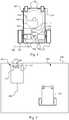
- Figure 1 shows a schematic overview of a robotic work tool 100 having a body 140 and a plurality of wheels 130.
- the robotic work tool 100 has 4 wheels 130, two front wheels 130' and the rear wheels 130". At least some of the wheels 130 are drivably connected to at least one electric motor 150. It should be noted that even if the description herein is focussed on electric motors, combustion engines may alternatively or additionally be used possibly in combination with an electric motor.
- the rear wheels 130" are connected to each an electric motor 150. This allows for driving the rear wheels 130" independently of one another which, for example, enables steep turning.
- the robotic work tool 100 also comprises a controller 110.
- the controller 110 may be implemented using instructions that enable hardware functionality, for example, by using executable computer program instructions in a general-purpose or special-purpose processor that may be stored on a computer readable storage medium (disk, memory etc) 120 to be executed by such a processor.
- the controller 110 is configured to read instructions from the memory 120 and execute these instructions to control the operation of the robotic work tool 100.
- the controller 110 may be implemented using any suitable, publically available processor or Programmable Logic Circuit (PLC).
- PLC Programmable Logic Circuit
- the memory 120 may be implemented using any commonly known technology for computer-readable memories such as ROM, RAM, SRAM, DRAM, FLASH, DDR, SDRAM or some other memory technology.
- the robotic work tool 100 further may have at least one sensor 170, in the example of figure 1 there are two sensors 170, arranged to detect a magnetic field (not shown).
- the sensors are connected to the controller 110 and the controller 110 is configured to process any signals received from the sensors 170.
- the sensor signals may be caused by the magnetic field caused by a control signal being transmitted through a boundary wire (for more details on charging stations, control signals and boundary wires, see the description below with reference to figure 2 ). This enables the controller 110 to determine whether the robotic work tool 100 is inside or outside an area enclosed by a boundary wire.
- teachings herein may also be used for a robotic work tool that is configured to operate in a work area, where the work area is not bounded by a boundary wire.
- robotic work tools are tools arranged to physically detect a boundary by collision detection, or a robotic work tool that uses a position determination system (such as GNSS) to maintain a position within the work area, which work area is specified by coordinates.
- GNSS position determination system
- the robotic work tool 100 may also or alternatively be arranged with a position determining device 190, such as a GNSS (Global Navigation Satellite System) device 190.
- a position determining device 190 such as a GNSS (Global Navigation Satellite System) device 190.
- the GNSS device is a GPS (Global Positioning Service) device 190.
- the GNSS device 190 is connected to the controller 110 for enabling the controller 110 to determine a current position for the robotic work tool 100 using the GNSS device and to control the movements of the robotic work tool 100 based on the position.
- the robotic work tool 100 may be arranged to operate within the work area solely or mainly based on the position determining device 190. A user may then establish a work area through coordinates and the robotic work tool will ensure that it stays within those coordinates based on the signals received by the position determining device 190.
- position determining devices 190 include optical (such as laser) position determining devices, other radio frequency position determining systems, such as ultrawideband (UWB) beacons and receivers.
- optical such as laser
- UWB ultrawideband
- the robotic work tool 100 may further be arranged with at least one sensor 195 for providing signals for deduced reckoning navigation.
- deduced reckoning navigation sensors 195 are odometers, accelerometers, gyroscopes and compasses.
- the deduced reckoning sensor(s) may be used to navigate in areas where satellite reception is not possible, i.e. areas hereafter referred to as shadowed areas.
- the controller 110 is connected to the motors 150 for controlling the propulsion of the robotic work tool 100 which enables the robotic work tool 100 to service an enclosed area without leaving the area.
- the robotic work tool 100 also comprises a work tool 160, which may be a grass cutting device, such as a rotating blade 160 driven by a cutter motor 165.
- the cutter motor 165 is connected to the controller 110 which enables the controller 110 to control the operation of the cutter motor 165.
- the controller is also configured to determine the load exerted on the rotating blade, by for example measure the power delivered to the cutter motor 165 or by measuring the axle torque exerted by the rotating blade.
- the robotic work tool 100 is, in one embodiment, a lawnmower robot.
- the robotic work tool 100 is a farming equipment.
- the robotic work tool 100 is a golf ball collecting tool.
- the robotic work tool 100 may also be a vacuum cleaner, a floor cleaner, a street sweeper, a snow removal tool, a mine clearance robot or any other robotic work tool that is required to operate in a work area in a methodical and systematic or position oriented manner.
- the robotic work tool 100 also has (at least) one battery 180 for providing power to the motors 150 and the cutter motor 165.
- the robotic work tool may have a fuel tank 180 for supplying fuel to any other type of engine 150.
- the robotic work tool is arranged with solar panel for supplying power to the battery 180.
- FIG. 2 shows a schematic view of a robotic work tool system 200 comprising a charging station 210 and a boundary wire 250 arranged to enclose a working area 205, the working area 205 not necessarily being a part of the robotic work tool system 200, in which the robotic work tool 100 is supposed to service.
- the robotic work tool 100 may be arranged to operate solely using the position determining device in which case no boundary wire 250 nor signal generator (to be disclosed) is part of the system 200.
- the charging station 210 has a charger 220 coupled to, in this embodiment, two charging plates 230.
- the charging plates 230 are arranged to co-operate with corresponding charging plates (not shown) of the robotic work tool 100 for charging the battery 180 of the robotic work tool 100.
- the charging station 210 also has, or may be coupled to, a signal generator 240 for providing a control signal (not shown) to be transmitted through the boundary wire 250.
- the control signal will generate a magnetic field around the boundary wire 250 which the sensors 170 of the robotic work tool 100 will detect.
- the robotic work tool 100 (or more accurately, the sensor 170) crosses the boundary wire 250 the direction of the magnetic field will change.
- the robotic work tool 100 will thus be able to determine that the boundary wire has been crossed.
- the use of more than one sensor 170 enables the controller 110 of the robotic work tool 100 to determine how the robotic work tool 100 is aligned with relation to the boundary wire 250 by comparing the sensor signals received from each sensor 170. This enables the robotic work tool to follow the boundary wire 250, for example when returning to the charging station 210 for charging.
- the charging station 210 also has a guide cable 260 for enabling the robotic work tool to find the entrance of the charging station 210.
- the guide cable 260 is formed by a loop of the boundary wire 250.
- the guide wire 260 is used to generate a magnetic field for enabling the robotic work tool 100 to find the charging station without following a guide cable 260.
- Figure 3 shows another schematic view of a robotic work tool system 200 according to the teachings herein, such as the robotic work tool system 200 of figure 2 , being depicted here at a larger scale.
- the work area 205 is shown here to include two obstacles 260 and being delimited by a boundary 250. It should be noted that there may be more or less than two obstacles 260.
- the boundary 250 may be effected through navigation coordinates or a boundary wire or other suitable means for defining a boundary for a work area for robotic work tools.
- Two obstacles 260A and 260B are shown in the example embodiment of figure 3 , one obstacle being a virtual obstacle 260A and one being an actual obstacle 260B.
- An obstacle marker in the form of a beacon marker 280 is arranged on or in each obstacle 260.
- the beacon markers 280 emit each a signal that marks an area 270 around the obstacle 260.
- the areas 270 may be of different size/radius.
- the area 270A for the virtual obstacle 260A being larger than the area 270B for the physical obstacle 260B.
- the area 270 of a beacon marker 280 may be regulated and possibly user settable by increasing or decreasing the signal power, or by programming the robotic work tool to detect a signal at a certain strength.
- the size relationship of the areas 270 in figure 3 are only examples and any internal relationship of sizes is possible and within the scope of this application.
- beacon sensor 175 is coupled to the controller 110 for determining the proximity to the beacon marker 280.
- the beacon sensor 175 is arranged to determine the proximity to the beacon marker 280 by itself and signal that a beacon marker is close by to the controller as the proximity of a beacon marker 280 is determined.
- the robotic work tool 100 is configured to determine the proximity to a beacon marker by comparing the signal strength (SSI) of the beacon signal, or a radio signal strength indicator (RSSI) of the beacon signal.
- SSI signal strength
- RSSI radio signal strength indicator
- the robotic work tool 100 is configured to determine the proximity to a beacon marker as a state close or not close by comparing the signal strength of the beacon signal to a threshold value. If the signal strength is above the threshold value, the beacon is close, and, if not, it is not close.
- the robotic work tool 100 is configured to determine the proximity to a beacon marker by comparing the signal strength of the beacon signal to a model of signal declination. In this embodiment the robotic work tool 100 is configured to know at what signal strengths the beacon signal is transmitted. This enables for determining a more precise distance to the beacon marker 280 and the robotic work tool 100 may take different actions depending on the actual distance. Such different actions may be to slow down or make a turn less than 180 degrees depending on the distance. For example, the robotic work tool may be configured to slow down if the distance is 5 m, to turn 90 degrees if the distance is 2 m, and to turn 180 degrees if the distance is less than 1 m.
- the robotic work tool 100 is configured to determine the proximity to a beacon marker by sending a signal to the beacon and measure the two-way response time or alternatively phrased to measure the time of arrival (TOA).
- TOA time of arrival
- the robotic work tool 100 is configured to determine the proximity to a beacon marker as a state close or not close by comparing the two-way response to a threshold value. If the two-way response is above the threshold value, the beacon is close, and, if not, it is not close.
- the robotic work tool 100 is configured to determine a more precise distance to the beacon marker 280 based on the two-way response. This enables for determining a more precise distance to the beacon marker 280 and the robotic work tool 100 may take different actions depending on the actual distance. Such different actions may be to slow down or make a turn less than 180 degrees depending on the distance. For example, the robotic work tool may be configured to slow down if the distance is 5 m, to turn 90 degrees if the distance is 2 m, and to turn 180 degrees if the distance is less than 1 m.
- the beacon marker 280 and the beacon sensor 175 are synchronized wherein the robotic work tool 100 need not transmit a signal to the beacon marker 280, but merely measures the time of arrival from a known last transmission time. Such an embodiment may operate in a manner similar to measure the two-way response time.
- FIG 4 shows a schematic view of a beacon marker 280.
- the beacon marker 280 is arranged to be fastened to an obstacle or a pole 260' (indicated with dashed lines).
- the beacon marker 280 may be fastened through various fastening means 281, such as, but not limited to, straps, belts, adhesive tape, VelcroTM to name a few examples.
- the beacon marker 280 is a radio frequency beacon emitting a radio frequency signal and the beacon sensor 175 is a radio frequency receiver (or transceiver).
- the beacon marker 280 is an ultrasonic beacon emitting an ultrasonic signal and the beacon sensor 175 is an ultrasonic receiver (or transceiver).
- an obstacle 260 is simple to mark by simply arranging a beacon marker on or adjacent to the obstacle 260. This is especially so for virtual obstacles 260A.
- Robotic work tools 100 may otherwise become stuck under such obstacles if collision detection is used.
- collision detection increases the wear and tear of the robotic work tool 100
- the collision detection systems may be highly sensitive to dirt and debris and may become blocked rendering the collision detection inefficient.
Landscapes
- Engineering & Computer Science (AREA)
- Power Engineering (AREA)
- Transportation (AREA)
- Mechanical Engineering (AREA)
- Physics & Mathematics (AREA)
- Remote Sensing (AREA)
- Radar, Positioning & Navigation (AREA)
- Life Sciences & Earth Sciences (AREA)
- Aviation & Aerospace Engineering (AREA)
- Environmental Sciences (AREA)
- General Physics & Mathematics (AREA)
- Automation & Control Theory (AREA)
- Acoustics & Sound (AREA)
- Sustainable Energy (AREA)
- Sustainable Development (AREA)
- Control Of Position, Course, Altitude, Or Attitude Of Moving Bodies (AREA)
Claims (11)
- Système de tondeuse à gazon robotisée (200) comprenant une tondeuse à gazon robotisée (100) configurée pour fonctionner dans une zone de travail, et un marqueur de balise (280), ladite tondeuse à gazon robotisée (100) comprenant un capteur de balise (175) configuré pour détecter un signal étant transmis par le marqueur de balise (280), dans lequel le système de tondeuse à gazon robotisée (200) est caractérisé en ce que ledit marqueur de balise (280) marque une zone (270) autour d'un obstacle temporaire (260) dans la zone de travail (205) dans laquelle ladite tondeuse à gazon robotisée (100) est agencée pour fonctionner, dans lequel ladite tondeuse à gazon robotisée est configurée pour :déterminer une proximité avec le marqueur de balise (280) et pour adapter son fonctionnement en conséquence, dans lequella tondeuse à gazon robotisée (100) est configurée pour déterminer la proximité avec le marqueur de balise (280) en envoyant un signal au marqueur de balise (280) et en mesurant un temps de réponse bidirectionnel.
- Système de tondeuse à gazon robotisée (200) selon la revendication 1, dans lequel la tondeuse à gazon robotisée (100) est en outre configurée pour
déterminer la proximité avec un marqueur de balise comme un état proche ou pas proche en comparant une intensité de signal du signal de balise à une valeur de seuil, et si la force du signal est supérieure à la valeur de seuil, le marqueur de balise (280) est proche et, sinon, il n'est pas proche. - Système de tondeuse à gazon robotisée (200) selon la revendication 1 ou 2, dans lequel la tondeuse à gazon robotisée (100) est configurée pour déterminer la proximité avec un marqueur de balise en comparant la force de signal du signal de balise à un modèle de déclinaison de signal.
- Système de tondeuse à gazon robotisée (200) selon la revendication 1, dans lequel la tondeuse à gazon robotisée (100) est configurée pour déterminer la proximité avec un marqueur de balise (280) comme un état proche ou pas proche en comparant le temps de réponse bidirectionnel à une valeur de seuil, et si le temps de réponse bidirectionnel est inférieur à la valeur de seuil, le marqueur de balise (280) est proche et, sinon, il n'est pas proche.
- Système de tondeuse à gazon robotisée (200) selon la revendication 1, dans lequel la tondeuse à gazon robotisée (100) est configurée pour déterminer une distance par rapport au marqueur de balise (280) sur la base du temps de réponse bidirectionnel.
- Système de tondeuse à gazon robotisée (200) selon l'une quelconque des revendications précédentes, dans lequel la tondeuse à gazon robotisée (100) est configurée pour adapter son fonctionnement lors de la détermination d'une proximité à un obstacle (260) en ralentissant ou en effectuant un virage de moins de 180 degrés.
- Système de tondeuse à gazon robotisée (200) selon l'une quelconque des revendications précédentes, dans lequel le marqueur de balise (280) et un capteur de balise (175) compris dans la tondeuse à gazon robotisée sont synchronisés.
- Système de tondeuse à gazon robotisée (200) selon l'une quelconque des revendications précédentes, dans lequel le marqueur de balise (280) est une balise radiofréquence.
- Système de tondeuse à gazon robotisée (200) selon l'une quelconque des revendications précédentes, dans lequel le marqueur de balise (280) est une balise à ultrasons.
- Système de tondeuse à gazon robotisée (200) selon l'une quelconque des revendications précédentes, dans lequel ledit marqueur de balise comprend un moyen de fixation (281) pour fixer ledit marqueur de balise (280) à un obstacle (260) ou à un poteau (260').
- Procédé de fonctionnement d'un système de tondeuse à gazon robotisée (200) comprenant une tondeuse à gazon robotisée (100) configurée pour fonctionner dans une zone de travail et un marqueur de balise (280), ladite tondeuse à gazon robotisée (100) comprenant un capteur de balise (175) configuré pour détecter un signal transmis par le marqueur de balise (280), caractérisé en ce que ledit marqueur de balise (280) marque une zone (270) autour d'un obstacle temporaire (260) dans la zone de travail (205) dans laquelle ladite tondeuse à gazon robotisée (100) est agencée pour fonctionner, ledit procédé comprenant
la détermination d'une proximité avec le marqueur de balise (280) et l'adaptation d'un fonctionnement de la tondeuse à gazon robotisée (100) en conséquence, et
dans lequel la proximité avec le marqueur de balise (280) est déterminée en envoyant un signal au marqueur de balise (280) et en mesurant un temps de réponse bidirectionnel.
Applications Claiming Priority (1)
| Application Number | Priority Date | Filing Date | Title |
|---|---|---|---|
| PCT/SE2013/051574 WO2015094052A1 (fr) | 2013-12-19 | 2013-12-19 | Détection d'obstacle pour outil de travail robotisé |
Publications (3)
| Publication Number | Publication Date |
|---|---|
| EP3084543A1 EP3084543A1 (fr) | 2016-10-26 |
| EP3084543A4 EP3084543A4 (fr) | 2017-09-06 |
| EP3084543B1 true EP3084543B1 (fr) | 2021-05-19 |
Family
ID=53403218
Family Applications (1)
| Application Number | Title | Priority Date | Filing Date |
|---|---|---|---|
| EP13899964.4A Active EP3084543B1 (fr) | 2013-12-19 | 2013-12-19 | Détection d'obstacle pour une tondeuse robotisée |
Country Status (3)
| Country | Link |
|---|---|
| US (2) | US10185325B2 (fr) |
| EP (1) | EP3084543B1 (fr) |
| WO (1) | WO2015094052A1 (fr) |
Families Citing this family (25)
| Publication number | Priority date | Publication date | Assignee | Title |
|---|---|---|---|---|
| US10281898B2 (en) | 2015-07-16 | 2019-05-07 | The Boeing Company | Method and system for controlling automated operations on a workpiece |
| US10146202B2 (en) * | 2015-07-16 | 2018-12-04 | The Boeing Company | Method and device for performing automated operations on a workpiece |
| US10034421B2 (en) | 2015-07-24 | 2018-07-31 | Irobot Corporation | Controlling robotic lawnmowers |
| DE102015222390A1 (de) * | 2015-11-13 | 2017-05-18 | Robert Bosch Gmbh | Autonomes Arbeitsgerät |
| US10649466B2 (en) * | 2015-12-02 | 2020-05-12 | Husqvarna Ab | Navigation for a vehicle by implementing two operating modes |
| EP3508049B1 (fr) | 2016-06-30 | 2022-08-24 | Techtronic Outdoor Products Technology Limited | Tondeuse à gazon autonome |
| US11172608B2 (en) | 2016-06-30 | 2021-11-16 | Tti (Macao Commercial Offshore) Limited | Autonomous lawn mower and a system for navigating thereof |
| DE102016226285A1 (de) * | 2016-12-29 | 2018-07-05 | Robert Bosch Gmbh | Haltesystem, insbesondere für Agraranwendungen |
| KR102070068B1 (ko) | 2017-11-30 | 2020-03-23 | 엘지전자 주식회사 | 이동 로봇 및 그 제어방법 |
| CN108283051A (zh) * | 2017-12-22 | 2018-07-17 | 宁波大叶园林设备股份有限公司 | 具智能机器人扫雪机通过局域网用于智慧花园的一站多机 |
| WO2018104927A2 (fr) * | 2018-03-20 | 2018-06-14 | Asociación De Municipios De Panamá - Amupa | Robot-tondeuse à gazon autonome en forme d'araignée |
| US11354815B2 (en) * | 2018-05-23 | 2022-06-07 | Samsung Electronics Co., Ltd. | Marker-based augmented reality system and method |
| CN110646762B (zh) * | 2018-06-26 | 2021-09-10 | 苏州触达信息技术有限公司 | 隧道内人员位置监测系统、方法和计算机可读存储介质 |
| CN112512300A (zh) | 2018-08-08 | 2021-03-16 | 托罗公司 | 用于训练自主车辆的手柄和方法及其存放方法 |
| CN120595785A (zh) | 2018-08-08 | 2025-09-05 | 苏州宝时得电动工具有限公司 | 自移动设备、自动工作系统及其控制方法 |
| CN109085836A (zh) * | 2018-08-29 | 2018-12-25 | 深圳市浦硕科技有限公司 | 一种扫地机器人回指定位置最短路线的方法 |
| KR102269851B1 (ko) * | 2019-01-31 | 2021-06-28 | 엘지전자 주식회사 | 이동 로봇 및 그 제어방법 |
| SE545353C2 (en) * | 2020-04-06 | 2023-07-18 | Husqvarna Ab | Adaptable operation for a robotic lawnmower |
| US12296694B2 (en) | 2021-03-10 | 2025-05-13 | Techtronic Cordless Gp | Lawnmowers |
| US12443180B2 (en) | 2021-11-10 | 2025-10-14 | Techtronic Cordless Gp | Robotic lawn mowers |
| AU2023200381A1 (en) | 2022-01-31 | 2023-08-17 | Techtronic Cordless Gp | Robotic garden tool |
| EP4270138A1 (fr) | 2022-04-28 | 2023-11-01 | Techtronic Cordless GP | Création d'une limite virtuelle pour un outil de jardin robotisé |
| US12472611B2 (en) | 2022-05-31 | 2025-11-18 | Techtronic Cordless Gp | Peg driver |
| AU2023204696A1 (en) | 2022-07-19 | 2024-02-08 | Techtronic Cordless Gp | Display for controlling robotic tool |
| AU2023206123A1 (en) | 2022-07-29 | 2024-02-15 | Techtronic Cordless Gp | Generation of a cryptography key for a robotic garden tool |
Citations (2)
| Publication number | Priority date | Publication date | Assignee | Title |
|---|---|---|---|---|
| US20100156660A1 (en) * | 2008-12-23 | 2010-06-24 | Lee In Ock | Apparatus and method for estimating position of mobile unit |
| US20130041526A1 (en) * | 2011-08-11 | 2013-02-14 | Chien Ouyang | Robotic Lawn Mower with Network Sensors |
Family Cites Families (59)
| Publication number | Priority date | Publication date | Assignee | Title |
|---|---|---|---|---|
| US5703464A (en) | 1995-06-28 | 1997-12-30 | Amerigon, Inc. | Radio frequency energy management system |
| IL124413A (en) | 1998-05-11 | 2001-05-20 | Friendly Robotics Ltd | System and method for area coverage with an autonomous robot |
| US6005367A (en) | 1998-07-14 | 1999-12-21 | Centurion International, Inc. | Smart power system |
| GB9820271D0 (en) | 1998-09-17 | 1998-11-11 | Simoco Int Ltd | A method of and apparatus for monitoring the condition of batteries used by a mobile radio telecommunications fleet |
| GB9827779D0 (en) * | 1998-12-18 | 1999-02-10 | Notetry Ltd | Improvements in or relating to appliances |
| GB2357028A (en) * | 1999-12-06 | 2001-06-13 | Notetry Ltd | Barrier for robotic floor cleaning device |
| GB2358843B (en) | 2000-02-02 | 2002-01-23 | Logical Technologies Ltd | An autonomous mobile apparatus for performing work within a pre-defined area |
| US20030034757A1 (en) | 2000-12-04 | 2003-02-20 | Woodnorth Douglas J. | Utilizing portable electrical power sources |
| KR200269832Y1 (ko) | 2001-12-28 | 2002-03-23 | (주)에스피에스 | 스마트 기능을 가지는 외장형 배터리팩 |
| US6674687B2 (en) | 2002-01-25 | 2004-01-06 | Navcom Technology, Inc. | System and method for navigation using two-way ultrasonic positioning |
| JP2005166001A (ja) | 2003-11-10 | 2005-06-23 | Funai Electric Co Ltd | 自動集塵装置 |
| KR100663402B1 (ko) | 2004-01-20 | 2007-01-02 | 엘지전자 주식회사 | 휴대용 단말기에서의 전력라인 통신장치 |
| US6913087B1 (en) | 2004-01-30 | 2005-07-05 | Black & Decker Inc. | System and method for communicating over power terminals in DC tools |
| US7385795B2 (en) | 2004-05-04 | 2008-06-10 | O2Micro International Limited | Cordless power tool with a protected weak link element |
| EP1805863B1 (fr) | 2004-10-18 | 2013-06-26 | Black & Decker, Inc. | Systeme electrique sans fil |
| US20100222926A1 (en) * | 2005-05-09 | 2010-09-02 | Ting-Yin Chiu | Virtual wall system |
| SE531000C2 (sv) | 2005-11-17 | 2008-11-11 | Atlas Copco Tools Ab | System för bibringande av de olika driftsegenskaper till ett batteridrivet skruvåtdragningsverktyg |
| EP1949345B1 (fr) | 2005-11-18 | 2010-01-13 | Metabowerke GmbH | Machine-outil electrique manuelle et batterie d'accumulateurs a cet effet |
| ES2522926T3 (es) * | 2005-12-02 | 2014-11-19 | Irobot Corporation | Robot Autónomo de Cubrimiento |
| US7953526B2 (en) * | 2006-01-18 | 2011-05-31 | I-Guide Robotics, Inc. | Robotic vehicle controller |
| US20070182576A1 (en) | 2006-02-09 | 2007-08-09 | 1673892 Ontario, Inc. | Remote battery monitoring |
| US20080150474A1 (en) | 2006-10-27 | 2008-06-26 | Ingersoll-Rand Company | Cordless power tool battery charging and analyzing system |
| KR101414321B1 (ko) * | 2007-05-09 | 2014-07-01 | 아이로보트 코퍼레이션 | 자동 커버리지 로봇 |
| EP2014423A3 (fr) | 2007-06-14 | 2014-01-22 | Black & Decker Inc. | Système d'identification de bloc-batterie |
| US8027761B1 (en) | 2007-09-04 | 2011-09-27 | Nelson Russell G | Local positioning system for automated lawn mowers |
| US20140000922A1 (en) | 2007-09-06 | 2014-01-02 | PELLENC (Société Anonyme) | Multifunctional portable electric apparatuses |
| EP2232670A4 (fr) | 2007-11-26 | 2012-06-27 | Gwacs Defense Inc | Système de batterie intelligente et procédés d'utilisation |
| JP2009259023A (ja) | 2008-04-17 | 2009-11-05 | Panasonic Corp | 自走式機器およびそのプログラム |
| US8031086B2 (en) * | 2008-12-10 | 2011-10-04 | Deere & Company | Method and system for determining a position of a vehicle |
| US9257865B2 (en) | 2009-01-22 | 2016-02-09 | Techtronic Power Tools Technology Limited | Wireless power distribution system and method |
| EP2581797B1 (fr) | 2009-05-15 | 2021-08-18 | Samsung Electronics Co., Ltd. | Procédé d'évitement de collision avec une balise pour un système de robot mobile |
| JP5476872B2 (ja) | 2009-09-04 | 2014-04-23 | 株式会社デンソー | 充電状態送信装置および外部充電システム |
| DE102009050547A1 (de) | 2009-10-23 | 2011-04-28 | Andreas Stihl Ag & Co. Kg | Elektrisches Arbeitsgerät mit einer Kommunikationsleitung zum Akkupack |
| JP2011135740A (ja) | 2009-12-25 | 2011-07-07 | Makita Corp | 電動工具用バッテリパックおよびバッテリ接続装置 |
| JP5524772B2 (ja) | 2010-09-02 | 2014-06-18 | 株式会社マキタ | 電池パック |
| JP5744509B2 (ja) | 2010-12-28 | 2015-07-08 | 株式会社マキタ | 電動工具用バッテリ |
| CN102142186B (zh) | 2011-03-01 | 2013-01-09 | 合肥国轩高科动力能源有限公司 | 锂电池组远程监控系统 |
| DE102011076963A1 (de) | 2011-06-06 | 2012-12-06 | Robert Bosch Gmbh | Batteriepaket mit einer separaten Energieversorgungseinrichtung für eine drahtlose Kommunikationseinrichtung des Batteriepakets |
| EP2735078B1 (fr) | 2011-07-24 | 2017-10-04 | Makita Corporation | Système d'outil électrique et adaptateur correspondant |
| US9146595B2 (en) | 2011-08-05 | 2015-09-29 | Qualcomm Incorporated | Systems and methods for remotely monitoring or controlling a battery |
| ES2733727T3 (es) | 2011-09-27 | 2019-12-02 | Nilfisk As | Paquete de batería con un sistema de control de la batería |
| WO2013063507A1 (fr) | 2011-10-26 | 2013-05-02 | Milwaukee Electric Tool Corporation | Suivi sans fil d'outils électriques et dispositifs associés |
| US9146560B2 (en) * | 2012-03-30 | 2015-09-29 | Irobot Corporation | System and method for implementing force field deterrent for robot |
| US9293928B2 (en) | 2013-04-23 | 2016-03-22 | Kevin Alexander | System and method for a dynamically configurable power distribution control and management system |
| US9590432B2 (en) | 2012-05-24 | 2017-03-07 | Hitachi Automotive Systems, Inc. | Battery control device comprising a plurality of cell controllers and being capable of determining whether a cell controller is operating abnormally |
| US20140107853A1 (en) | 2012-06-26 | 2014-04-17 | Black & Decker Inc. | System for enhancing power tools |
| US20150316913A1 (en) | 2012-07-09 | 2015-11-05 | Techtronic Outdoor Products Technology Limited | An interface for a power tool |
| US20140035357A1 (en) | 2012-08-01 | 2014-02-06 | Infineon Technologies Ag | Battery, Battery Management System, and Method to Control a Battery |
| CN103000826A (zh) | 2012-11-12 | 2013-03-27 | 北京慧网通达科技股份有限公司 | 具有无线标签读写功能的便携式设备用电池和便携式设备 |
| US9466198B2 (en) | 2013-02-22 | 2016-10-11 | Milwaukee Electric Tool Corporation | Wireless tracking of power tools and related devices |
| JP6474950B2 (ja) | 2013-03-28 | 2019-02-27 | 株式会社マキタ | 電動機器システム |
| JP6103392B2 (ja) | 2013-03-29 | 2017-03-29 | パナソニックIpマネジメント株式会社 | 蓄電池パック、電気機器、通信制御方法 |
| JP2014205978A (ja) | 2013-04-11 | 2014-10-30 | トヨタ自動車株式会社 | スマートエントリー用携帯機 |
| CA2908155A1 (fr) | 2013-04-11 | 2014-10-16 | Sony Corporation | Dispositif de batterie |
| US20140342193A1 (en) | 2013-05-17 | 2014-11-20 | Tenergy Corporation | Smart battery system |
| US20150042291A1 (en) | 2013-08-08 | 2015-02-12 | Instavolt Inc. | Method and System for Communication with a Battery Charger |
| CN104512494A (zh) | 2013-09-29 | 2015-04-15 | 凹凸电子(武汉)有限公司 | 电动车辆及其管理方法 |
| US10131042B2 (en) | 2013-10-21 | 2018-11-20 | Milwaukee Electric Tool Corporation | Adapter for power tool devices |
| EP3369292B1 (fr) | 2015-10-30 | 2020-12-02 | Milwaukee Electric Tool Corporation | Commande, configuration et contrôle de lumière à distance |
-
2013
- 2013-12-19 WO PCT/SE2013/051574 patent/WO2015094052A1/fr not_active Ceased
- 2013-12-19 EP EP13899964.4A patent/EP3084543B1/fr active Active
- 2013-12-19 US US15/105,013 patent/US10185325B2/en active Active
-
2018
- 2018-12-10 US US16/215,123 patent/US10782705B2/en active Active
Patent Citations (2)
| Publication number | Priority date | Publication date | Assignee | Title |
|---|---|---|---|---|
| US20100156660A1 (en) * | 2008-12-23 | 2010-06-24 | Lee In Ock | Apparatus and method for estimating position of mobile unit |
| US20130041526A1 (en) * | 2011-08-11 | 2013-02-14 | Chien Ouyang | Robotic Lawn Mower with Network Sensors |
Also Published As
| Publication number | Publication date |
|---|---|
| WO2015094052A1 (fr) | 2015-06-25 |
| EP3084543A1 (fr) | 2016-10-26 |
| US20170031360A1 (en) | 2017-02-02 |
| US10185325B2 (en) | 2019-01-22 |
| US20190113923A1 (en) | 2019-04-18 |
| EP3084543A4 (fr) | 2017-09-06 |
| US10782705B2 (en) | 2020-09-22 |
Similar Documents
| Publication | Publication Date | Title |
|---|---|---|
| US10782705B2 (en) | Obstacle detection for a robotic working tool | |
| US10646997B2 (en) | Navigation for a robotic working tool | |
| EP3084541B1 (fr) | Navigation adaptée à un outil de travail robotisé | |
| US10136576B2 (en) | Navigation for a robotic working tool | |
| EP3084542B1 (fr) | Système et procédé permettant la navigation d'un outil de travail robotique | |
| US10598793B2 (en) | Navigation for a robotic work tool | |
| US12487602B2 (en) | Navigation for a robotic work tool | |
| EP3236734B1 (fr) | Fonctionnement amélioré d'un outil de travail robotique en adaptant le fonctionnement aux conditions météorologiques | |
| US20230117845A1 (en) | System and method for improved navigation of a robotic work tool | |
| EP4068040A1 (fr) | Fonctionnement amélioré pour un outil de travail robotique | |
| EP4314974A1 (fr) | Navigation améliorée pour outil de travail robotique | |
| WO2021244883A1 (fr) | Procédé de fourniture d'une estimation de position d'un outil robotique, outil robotique et système d'outils robotiques |
Legal Events
| Date | Code | Title | Description |
|---|---|---|---|
| PUAI | Public reference made under article 153(3) epc to a published international application that has entered the european phase |
Free format text: ORIGINAL CODE: 0009012 |
|
| 17P | Request for examination filed |
Effective date: 20160706 |
|
| AK | Designated contracting states |
Kind code of ref document: A1 Designated state(s): AL AT BE BG CH CY CZ DE DK EE ES FI FR GB GR HR HU IE IS IT LI LT LU LV MC MK MT NL NO PL PT RO RS SE SI SK SM TR |
|
| AX | Request for extension of the european patent |
Extension state: BA ME |
|
| DAX | Request for extension of the european patent (deleted) | ||
| A4 | Supplementary search report drawn up and despatched |
Effective date: 20170803 |
|
| RIC1 | Information provided on ipc code assigned before grant |
Ipc: B60L 15/20 20060101ALI20170728BHEP Ipc: A01D 34/00 20060101ALI20170728BHEP Ipc: B60L 1/00 20060101ALI20170728BHEP Ipc: B60L 11/14 20060101ALI20170728BHEP Ipc: G01S 1/68 20060101ALI20170728BHEP Ipc: B60L 8/00 20060101ALI20170728BHEP Ipc: B60L 11/18 20060101ALI20170728BHEP Ipc: G01S 1/72 20060101ALI20170728BHEP Ipc: G05D 1/02 20060101AFI20170728BHEP Ipc: A01D 75/18 20060101ALI20170728BHEP |
|
| STAA | Information on the status of an ep patent application or granted ep patent |
Free format text: STATUS: EXAMINATION IS IN PROGRESS |
|
| 17Q | First examination report despatched |
Effective date: 20190104 |
|
| RIC1 | Information provided on ipc code assigned before grant |
Ipc: B60L 15/20 20060101ALI20201106BHEP Ipc: G01S 1/72 20060101ALI20201106BHEP Ipc: B60L 50/16 20190101ALI20201106BHEP Ipc: G05D 1/02 20200101AFI20201106BHEP Ipc: B60L 53/30 20190101ALI20201106BHEP Ipc: B60L 50/52 20190101ALI20201106BHEP Ipc: B60L 1/00 20060101ALI20201106BHEP Ipc: A01D 75/18 20060101ALI20201106BHEP Ipc: G01S 1/68 20060101ALI20201106BHEP Ipc: B60L 8/00 20060101ALI20201106BHEP Ipc: A01D 34/00 20060101ALI20201106BHEP |
|
| GRAP | Despatch of communication of intention to grant a patent |
Free format text: ORIGINAL CODE: EPIDOSNIGR1 |
|
| STAA | Information on the status of an ep patent application or granted ep patent |
Free format text: STATUS: GRANT OF PATENT IS INTENDED |
|
| INTG | Intention to grant announced |
Effective date: 20201222 |
|
| GRAS | Grant fee paid |
Free format text: ORIGINAL CODE: EPIDOSNIGR3 |
|
| GRAA | (expected) grant |
Free format text: ORIGINAL CODE: 0009210 |
|
| STAA | Information on the status of an ep patent application or granted ep patent |
Free format text: STATUS: THE PATENT HAS BEEN GRANTED |
|
| AK | Designated contracting states |
Kind code of ref document: B1 Designated state(s): AL AT BE BG CH CY CZ DE DK EE ES FI FR GB GR HR HU IE IS IT LI LT LU LV MC MK MT NL NO PL PT RO RS SE SI SK SM TR |
|
| REG | Reference to a national code |
Ref country code: GB Ref legal event code: FG4D |
|
| REG | Reference to a national code |
Ref country code: CH Ref legal event code: EP |
|
| REG | Reference to a national code |
Ref country code: DE Ref legal event code: R096 Ref document number: 602013077607 Country of ref document: DE |
|
| REG | Reference to a national code |
Ref country code: AT Ref legal event code: REF Ref document number: 1394608 Country of ref document: AT Kind code of ref document: T Effective date: 20210615 |
|
| REG | Reference to a national code |
Ref country code: IE Ref legal event code: FG4D |
|
| REG | Reference to a national code |
Ref country code: LT Ref legal event code: MG9D |
|
| REG | Reference to a national code |
Ref country code: AT Ref legal event code: MK05 Ref document number: 1394608 Country of ref document: AT Kind code of ref document: T Effective date: 20210519 |
|
| REG | Reference to a national code |
Ref country code: NL Ref legal event code: MP Effective date: 20210519 |
|
| PG25 | Lapsed in a contracting state [announced via postgrant information from national office to epo] |
Ref country code: LT Free format text: LAPSE BECAUSE OF FAILURE TO SUBMIT A TRANSLATION OF THE DESCRIPTION OR TO PAY THE FEE WITHIN THE PRESCRIBED TIME-LIMIT Effective date: 20210519 Ref country code: FI Free format text: LAPSE BECAUSE OF FAILURE TO SUBMIT A TRANSLATION OF THE DESCRIPTION OR TO PAY THE FEE WITHIN THE PRESCRIBED TIME-LIMIT Effective date: 20210519 Ref country code: BG Free format text: LAPSE BECAUSE OF FAILURE TO SUBMIT A TRANSLATION OF THE DESCRIPTION OR TO PAY THE FEE WITHIN THE PRESCRIBED TIME-LIMIT Effective date: 20210819 Ref country code: AT Free format text: LAPSE BECAUSE OF FAILURE TO SUBMIT A TRANSLATION OF THE DESCRIPTION OR TO PAY THE FEE WITHIN THE PRESCRIBED TIME-LIMIT Effective date: 20210519 Ref country code: HR Free format text: LAPSE BECAUSE OF FAILURE TO SUBMIT A TRANSLATION OF THE DESCRIPTION OR TO PAY THE FEE WITHIN THE PRESCRIBED TIME-LIMIT Effective date: 20210519 |
|
| PG25 | Lapsed in a contracting state [announced via postgrant information from national office to epo] |
Ref country code: LV Free format text: LAPSE BECAUSE OF FAILURE TO SUBMIT A TRANSLATION OF THE DESCRIPTION OR TO PAY THE FEE WITHIN THE PRESCRIBED TIME-LIMIT Effective date: 20210519 Ref country code: GR Free format text: LAPSE BECAUSE OF FAILURE TO SUBMIT A TRANSLATION OF THE DESCRIPTION OR TO PAY THE FEE WITHIN THE PRESCRIBED TIME-LIMIT Effective date: 20210820 Ref country code: IS Free format text: LAPSE BECAUSE OF FAILURE TO SUBMIT A TRANSLATION OF THE DESCRIPTION OR TO PAY THE FEE WITHIN THE PRESCRIBED TIME-LIMIT Effective date: 20210919 Ref country code: ES Free format text: LAPSE BECAUSE OF FAILURE TO SUBMIT A TRANSLATION OF THE DESCRIPTION OR TO PAY THE FEE WITHIN THE PRESCRIBED TIME-LIMIT Effective date: 20210519 Ref country code: PT Free format text: LAPSE BECAUSE OF FAILURE TO SUBMIT A TRANSLATION OF THE DESCRIPTION OR TO PAY THE FEE WITHIN THE PRESCRIBED TIME-LIMIT Effective date: 20210920 Ref country code: NO Free format text: LAPSE BECAUSE OF FAILURE TO SUBMIT A TRANSLATION OF THE DESCRIPTION OR TO PAY THE FEE WITHIN THE PRESCRIBED TIME-LIMIT Effective date: 20210819 Ref country code: PL Free format text: LAPSE BECAUSE OF FAILURE TO SUBMIT A TRANSLATION OF THE DESCRIPTION OR TO PAY THE FEE WITHIN THE PRESCRIBED TIME-LIMIT Effective date: 20210519 Ref country code: SE Free format text: LAPSE BECAUSE OF FAILURE TO SUBMIT A TRANSLATION OF THE DESCRIPTION OR TO PAY THE FEE WITHIN THE PRESCRIBED TIME-LIMIT Effective date: 20210519 Ref country code: RS Free format text: LAPSE BECAUSE OF FAILURE TO SUBMIT A TRANSLATION OF THE DESCRIPTION OR TO PAY THE FEE WITHIN THE PRESCRIBED TIME-LIMIT Effective date: 20210519 |
|
| PG25 | Lapsed in a contracting state [announced via postgrant information from national office to epo] |
Ref country code: NL Free format text: LAPSE BECAUSE OF FAILURE TO SUBMIT A TRANSLATION OF THE DESCRIPTION OR TO PAY THE FEE WITHIN THE PRESCRIBED TIME-LIMIT Effective date: 20210519 |
|
| PG25 | Lapsed in a contracting state [announced via postgrant information from national office to epo] |
Ref country code: RO Free format text: LAPSE BECAUSE OF FAILURE TO SUBMIT A TRANSLATION OF THE DESCRIPTION OR TO PAY THE FEE WITHIN THE PRESCRIBED TIME-LIMIT Effective date: 20210519 Ref country code: SM Free format text: LAPSE BECAUSE OF FAILURE TO SUBMIT A TRANSLATION OF THE DESCRIPTION OR TO PAY THE FEE WITHIN THE PRESCRIBED TIME-LIMIT Effective date: 20210519 Ref country code: SK Free format text: LAPSE BECAUSE OF FAILURE TO SUBMIT A TRANSLATION OF THE DESCRIPTION OR TO PAY THE FEE WITHIN THE PRESCRIBED TIME-LIMIT Effective date: 20210519 Ref country code: EE Free format text: LAPSE BECAUSE OF FAILURE TO SUBMIT A TRANSLATION OF THE DESCRIPTION OR TO PAY THE FEE WITHIN THE PRESCRIBED TIME-LIMIT Effective date: 20210519 Ref country code: CZ Free format text: LAPSE BECAUSE OF FAILURE TO SUBMIT A TRANSLATION OF THE DESCRIPTION OR TO PAY THE FEE WITHIN THE PRESCRIBED TIME-LIMIT Effective date: 20210519 Ref country code: DK Free format text: LAPSE BECAUSE OF FAILURE TO SUBMIT A TRANSLATION OF THE DESCRIPTION OR TO PAY THE FEE WITHIN THE PRESCRIBED TIME-LIMIT Effective date: 20210519 |
|
| REG | Reference to a national code |
Ref country code: DE Ref legal event code: R097 Ref document number: 602013077607 Country of ref document: DE |
|
| PLBE | No opposition filed within time limit |
Free format text: ORIGINAL CODE: 0009261 |
|
| STAA | Information on the status of an ep patent application or granted ep patent |
Free format text: STATUS: NO OPPOSITION FILED WITHIN TIME LIMIT |
|
| 26N | No opposition filed |
Effective date: 20220222 |
|
| PG25 | Lapsed in a contracting state [announced via postgrant information from national office to epo] |
Ref country code: IS Free format text: LAPSE BECAUSE OF FAILURE TO SUBMIT A TRANSLATION OF THE DESCRIPTION OR TO PAY THE FEE WITHIN THE PRESCRIBED TIME-LIMIT Effective date: 20210919 Ref country code: AL Free format text: LAPSE BECAUSE OF FAILURE TO SUBMIT A TRANSLATION OF THE DESCRIPTION OR TO PAY THE FEE WITHIN THE PRESCRIBED TIME-LIMIT Effective date: 20210519 |
|
| PG25 | Lapsed in a contracting state [announced via postgrant information from national office to epo] |
Ref country code: MC Free format text: LAPSE BECAUSE OF FAILURE TO SUBMIT A TRANSLATION OF THE DESCRIPTION OR TO PAY THE FEE WITHIN THE PRESCRIBED TIME-LIMIT Effective date: 20210519 Ref country code: IT Free format text: LAPSE BECAUSE OF FAILURE TO SUBMIT A TRANSLATION OF THE DESCRIPTION OR TO PAY THE FEE WITHIN THE PRESCRIBED TIME-LIMIT Effective date: 20210519 |
|
| PG25 | Lapsed in a contracting state [announced via postgrant information from national office to epo] |
Ref country code: LU Free format text: LAPSE BECAUSE OF NON-PAYMENT OF DUE FEES Effective date: 20211219 Ref country code: IE Free format text: LAPSE BECAUSE OF NON-PAYMENT OF DUE FEES Effective date: 20211219 |
|
| PG25 | Lapsed in a contracting state [announced via postgrant information from national office to epo] |
Ref country code: HU Free format text: LAPSE BECAUSE OF FAILURE TO SUBMIT A TRANSLATION OF THE DESCRIPTION OR TO PAY THE FEE WITHIN THE PRESCRIBED TIME-LIMIT; INVALID AB INITIO Effective date: 20131219 |
|
| P01 | Opt-out of the competence of the unified patent court (upc) registered |
Effective date: 20230419 |
|
| PG25 | Lapsed in a contracting state [announced via postgrant information from national office to epo] |
Ref country code: CY Free format text: LAPSE BECAUSE OF FAILURE TO SUBMIT A TRANSLATION OF THE DESCRIPTION OR TO PAY THE FEE WITHIN THE PRESCRIBED TIME-LIMIT Effective date: 20210519 |
|
| REG | Reference to a national code |
Ref country code: DE Ref legal event code: R079 Ref document number: 602013077607 Country of ref document: DE Free format text: PREVIOUS MAIN CLASS: G05D0001020000 Ipc: G05D0001430000 |
|
| PGFP | Annual fee paid to national office [announced via postgrant information from national office to epo] |
Ref country code: GB Payment date: 20231106 Year of fee payment: 11 |
|
| PGFP | Annual fee paid to national office [announced via postgrant information from national office to epo] |
Ref country code: FR Payment date: 20231107 Year of fee payment: 11 |
|
| PGFP | Annual fee paid to national office [announced via postgrant information from national office to epo] |
Ref country code: BE Payment date: 20231106 Year of fee payment: 11 |
|
| PG25 | Lapsed in a contracting state [announced via postgrant information from national office to epo] |
Ref country code: MK Free format text: LAPSE BECAUSE OF FAILURE TO SUBMIT A TRANSLATION OF THE DESCRIPTION OR TO PAY THE FEE WITHIN THE PRESCRIBED TIME-LIMIT Effective date: 20210519 |
|
| PGFP | Annual fee paid to national office [announced via postgrant information from national office to epo] |
Ref country code: CH Payment date: 20240101 Year of fee payment: 11 |
|
| PG25 | Lapsed in a contracting state [announced via postgrant information from national office to epo] |
Ref country code: MT Free format text: LAPSE BECAUSE OF FAILURE TO SUBMIT A TRANSLATION OF THE DESCRIPTION OR TO PAY THE FEE WITHIN THE PRESCRIBED TIME-LIMIT Effective date: 20210519 |
|
| PGFP | Annual fee paid to national office [announced via postgrant information from national office to epo] |
Ref country code: DE Payment date: 20241111 Year of fee payment: 12 |
|
| REG | Reference to a national code |
Ref country code: CH Ref legal event code: PL |
|
| GBPC | Gb: european patent ceased through non-payment of renewal fee |
Effective date: 20241219 |
|
| REG | Reference to a national code |
Ref country code: BE Ref legal event code: MM Effective date: 20241231 |
|
| PG25 | Lapsed in a contracting state [announced via postgrant information from national office to epo] |
Ref country code: GB Free format text: LAPSE BECAUSE OF NON-PAYMENT OF DUE FEES Effective date: 20241219 Ref country code: BE Free format text: LAPSE BECAUSE OF NON-PAYMENT OF DUE FEES Effective date: 20241231 |
|
| PG25 | Lapsed in a contracting state [announced via postgrant information from national office to epo] |
Ref country code: FR Free format text: LAPSE BECAUSE OF NON-PAYMENT OF DUE FEES Effective date: 20241231 |
|
| PG25 | Lapsed in a contracting state [announced via postgrant information from national office to epo] |
Ref country code: CH Free format text: LAPSE BECAUSE OF NON-PAYMENT OF DUE FEES Effective date: 20241231 |
|
| PG25 | Lapsed in a contracting state [announced via postgrant information from national office to epo] |
Ref country code: TR Free format text: LAPSE BECAUSE OF FAILURE TO SUBMIT A TRANSLATION OF THE DESCRIPTION OR TO PAY THE FEE WITHIN THE PRESCRIBED TIME-LIMIT Effective date: 20210519 |