EP3084545B1 - Dynamisches ausgleichsventil zur steuerung des durchflusses unabhängig vom druck - Google Patents
Dynamisches ausgleichsventil zur steuerung des durchflusses unabhängig vom druck Download PDFInfo
- Publication number
- EP3084545B1 EP3084545B1 EP14800053.2A EP14800053A EP3084545B1 EP 3084545 B1 EP3084545 B1 EP 3084545B1 EP 14800053 A EP14800053 A EP 14800053A EP 3084545 B1 EP3084545 B1 EP 3084545B1
- Authority
- EP
- European Patent Office
- Prior art keywords
- equipment
- valve
- flow rate
- main equipment
- orifice
- Prior art date
- Legal status (The legal status is an assumption and is not a legal conclusion. Google has not performed a legal analysis and makes no representation as to the accuracy of the status listed.)
- Active
Links
Images


Classifications
-
- G—PHYSICS
- G05—CONTROLLING; REGULATING
- G05D—SYSTEMS FOR CONTROLLING OR REGULATING NON-ELECTRIC VARIABLES
- G05D7/00—Control of flow
- G05D7/06—Control of flow characterised by the use of electric means
- G05D7/0617—Control of flow characterised by the use of electric means specially adapted for fluid materials
- G05D7/0629—Control of flow characterised by the use of electric means specially adapted for fluid materials characterised by the type of regulator means
- G05D7/0635—Control of flow characterised by the use of electric means specially adapted for fluid materials characterised by the type of regulator means by action on throttling means
-
- G—PHYSICS
- G05—CONTROLLING; REGULATING
- G05D—SYSTEMS FOR CONTROLLING OR REGULATING NON-ELECTRIC VARIABLES
- G05D7/00—Control of flow
- G05D7/005—Control of flow characterised by the use of auxiliary non-electric power combined with the use of electric means
-
- G—PHYSICS
- G05—CONTROLLING; REGULATING
- G05D—SYSTEMS FOR CONTROLLING OR REGULATING NON-ELECTRIC VARIABLES
- G05D16/00—Control of fluid pressure
- G05D16/04—Control of fluid pressure without auxiliary power
- G05D16/06—Control of fluid pressure without auxiliary power the sensing element being a flexible membrane, yielding to pressure, e.g. diaphragm, bellows, capsule
- G05D16/063—Control of fluid pressure without auxiliary power the sensing element being a flexible membrane, yielding to pressure, e.g. diaphragm, bellows, capsule the sensing element being a membrane
- G05D16/0644—Control of fluid pressure without auxiliary power the sensing element being a flexible membrane, yielding to pressure, e.g. diaphragm, bellows, capsule the sensing element being a membrane the membrane acting directly on the obturator
- G05D16/0655—Control of fluid pressure without auxiliary power the sensing element being a flexible membrane, yielding to pressure, e.g. diaphragm, bellows, capsule the sensing element being a membrane the membrane acting directly on the obturator using one spring-loaded membrane
-
- G—PHYSICS
- G05—CONTROLLING; REGULATING
- G05D—SYSTEMS FOR CONTROLLING OR REGULATING NON-ELECTRIC VARIABLES
- G05D7/00—Control of flow
- G05D7/01—Control of flow without auxiliary power
- G05D7/0106—Control of flow without auxiliary power the sensing element being a flexible member, e.g. bellows, diaphragm, capsule
-
- Y—GENERAL TAGGING OF NEW TECHNOLOGICAL DEVELOPMENTS; GENERAL TAGGING OF CROSS-SECTIONAL TECHNOLOGIES SPANNING OVER SEVERAL SECTIONS OF THE IPC; TECHNICAL SUBJECTS COVERED BY FORMER USPC CROSS-REFERENCE ART COLLECTIONS [XRACs] AND DIGESTS
- Y10—TECHNICAL SUBJECTS COVERED BY FORMER USPC
- Y10T—TECHNICAL SUBJECTS COVERED BY FORMER US CLASSIFICATION
- Y10T137/00—Fluid handling
- Y10T137/7722—Line condition change responsive valves
- Y10T137/7781—With separate connected fluid reactor surface
- Y10T137/7784—Responsive to change in rate of fluid flow
- Y10T137/7787—Expansible chamber subject to differential pressures
- Y10T137/7791—Pressures across flow line valve
-
- Y—GENERAL TAGGING OF NEW TECHNOLOGICAL DEVELOPMENTS; GENERAL TAGGING OF CROSS-SECTIONAL TECHNOLOGIES SPANNING OVER SEVERAL SECTIONS OF THE IPC; TECHNICAL SUBJECTS COVERED BY FORMER USPC CROSS-REFERENCE ART COLLECTIONS [XRACs] AND DIGESTS
- Y10—TECHNICAL SUBJECTS COVERED BY FORMER USPC
- Y10T—TECHNICAL SUBJECTS COVERED BY FORMER US CLASSIFICATION
- Y10T137/00—Fluid handling
- Y10T137/8593—Systems
- Y10T137/87917—Flow path with serial valves and/or closures
- Y10T137/87981—Common actuator
-
- Y—GENERAL TAGGING OF NEW TECHNOLOGICAL DEVELOPMENTS; GENERAL TAGGING OF CROSS-SECTIONAL TECHNOLOGIES SPANNING OVER SEVERAL SECTIONS OF THE IPC; TECHNICAL SUBJECTS COVERED BY FORMER USPC CROSS-REFERENCE ART COLLECTIONS [XRACs] AND DIGESTS
- Y10—TECHNICAL SUBJECTS COVERED BY FORMER USPC
- Y10T—TECHNICAL SUBJECTS COVERED BY FORMER US CLASSIFICATION
- Y10T137/00—Fluid handling
- Y10T137/8593—Systems
- Y10T137/87917—Flow path with serial valves and/or closures
- Y10T137/88038—One valve head carries other valve head
Definitions
- the present invention relates to a valve for dynamic balancing of the flow rates of thermal carrier fluid independent of the fluctuations of pressure in hydraulic systems in an environment of HVAC (heating, ventilation and air conditioning) and of distribution of sanitary water and automatic regulation of the flow rate of feeding of terminal units, heat exchangers, fan coils, AHU batteries, metering units and the like.
- HVAC heating, ventilation and air conditioning
- valves known as PICV (pressure independent control valves) whereof a schematic representation (typical but not the only one possible) is given in the accompanying Fig. 1
- PICV pressure independent control valves
- a functional unit " ⁇ p" suitable for maintaining constant the differential pressure between upstream and downstream of a functional unit "Kv"
- Kv a functional unit
- the latter being made up of at least one orifice whose area of passage can be made to vary up to total closure by means of manual actuation and/or by means of an actuator "M" of whatsoever kind.
- the PICV valves therefore carry out typically the following functions:
- the functional unit " ⁇ p" assigned to function 2) i.e. maintaining constant the pressure differential P 2 -P 3 on either side of the regulation unit "Kv"
- a cut-off which chokes an orifice, cut-off actuated by a diaphragm which senses the differential pressure P 2 -P 3 : when the variations in pressures upstream of the valve P 1 or downstream of the valve P 3 seek to vary also the differential P 2 -P 3 , the diaphragm senses an imbalance in the design value and therefore moves the lamination cut-off which will vary the differential P 1 -P 2 in an opposed manner so that the value P 2 -P 3 will be restored to the design one.
- the functional unit "Kv" is assigned to perform the other functions 1), 3) and 4).
- the function 1) of presetting is typically performed by an orifice/cut-off pair wherein the position of the cut-off relative to the orifice is made to change with manual mechanical operations, typically on installation of the valve or in any case during one-off regulation or maintenance of the system, consequently varying the area of passage and therefore the maximum rate of flow which from that time onwards may traverse it.
- the function 3 of modulation of the flow rate is typically performed by an orifice/cut-off pair wherein the position of the cut-off relative to the orifice and therefore the resulting area of passage is made to change mechanically by an actuator (thermostatic, thermoelectric, electromechanical, solenoid, managed with direct feedback from the valve or remote, etc.) during the normal regime of functioning of the system so as to vary the rate of flow which may traverse the valve in order to modify in time the point of regulation of the end unit or branch controlled by the valve.
- an actuator thermostatic, thermoelectric, electromechanical, solenoid, managed with direct feedback from the valve or remote, etc.
- the on-off function 4) is typically performed by an orifice/cut-off pair wherein the cut-off is brought, manually or by means of an actuator of whatsoever kind, to occlude totally the area of the orifice so as to inhibit the flowing of the thermal carrier fluid to the subsequent components of the system.
- the mobile equipment then has to be moved further to perform the function of modulation of the flow rate 3) wherein, in order to modulate the flow rate in time, the linear actuator mounted on the valve body further varies the position of the mobile equipment between the presetting position set and the minimum opening.
- the action of manual presetting moves the end part of the rod of the cut-off equipment 4 away from the presser 7 of the actuator 6, thus making sure that during the subsequent phase of control modulating the movement of the presser no effect arises until it has once again reached the terminal end of the rod, all this however using a portion of the stroke, limited, made available by the actuator.
- the stroke which can be used for the modulating regulation is reduced, with respect to the maximum one available, by the section used at presetting for the limitation of the maximum rate of flow which can traverse the valve: the regulation of the flow rate between the maximum ceiling and the minimum value allowed by the structure of the valve must therefore be distributed over a residual length which can also be very small (especially in heating systems where work is carried out with minimum flow rates), length over which the errors due to the inevitable mechanical, dimensional and coupling tolerances of the various components and of the actuator will be found to weigh increasingly in percentage terms, reducing in parallel the capacities for regulation of the valve and the precision of the regulation itself.
- valves disclosed in WO 2006/136158 A1 and WO 2009/135490 A2 represent two solutions to this problem, where regulation of the maximum flow rate takes place through rotation of two cylindrical elements whose degree of circumferential overlapping of the respective openings allows the maximum flow rate to be preset while the entire stroke of the pusher of the actuator is used for the axial translation of one of the two elements in the first case or of the entire equipment formed by the two elements in the second, permitting the further regulation of the flow rate which traverses the valve from the preset maximum value to zero.
- both the abovementioned solutions can be realised only by means of very heavy and voluminous metal components which are complex to machine and therefore very costly, or by using components made in plastic material which is very sensitive to the environmental conditions as far as thermal expansions are concerned (therefore problems of precision during regulation) and of lower capacity for maintaining in time the functional features and therefore working life of the valve.
- the object of the invention is that of obviating the aforesaid functional limits of the PICV valves of the prior art.
- PICV valve which has the following features:
- the dynamic balancing valve for pressure independent flow rate control apt to be placed in hydraulic systems between an upstream fluid inlet duct and a downstream outlet duct, comprises a first functional unit "Kv" arranged between said inlet duct and said outlet duct, comprising mobile equipment which can be actuated manually or by means of an actuator for setting and modifying the span of a fluid passage orifice, and thus the valve flow rate, up to complete closure; and a second functional unit “ ⁇ p” apt to maintain the differential pressure on the two sides (between upstream and downstream) of said first unit "Kv” constant, and therefore the set flow rate of the valve independently of the fluctuations of the pressures in the hydraulic system, wherein said mobile equipment comprises main equipment and secondary equipment which can translate linearly with respect to the main equipment for presetting the maximum valve flow rate, the main equipment carrying integrally the secondary equipment and can be linearly displaced by means of said actuator for modulating the fluid flow rate from the preset maximum one up to complete closure.
- the lower valve body 11 houses the aforesaid second functional unit " ⁇ p", suitable for maintaining constant the pressure differential between upstream and downstream of said first functional unit "Kv”, housed substantially in said upper body 12.
- the second functional unit " ⁇ p” is assigned to function 2), previously disclosed, i.e. to maintain constant the pressure differential between upstream and downstream of the first functional unit "Kv", and therefore to maintain the flow rate set independently of the fluctuations of the pressures in the hydraulic system wherein the valve is installed.
- the first functional unit "Kv” is instead assigned the other three functions 1), 3) and 4), respectively of presetting, modulation and complete closure (on-off) of the valve.
- the second unit " ⁇ p" is placed between an inlet duct 13 of the fluid in the valve and an outlet duct 14, formed respectively in the lower valve body 11 and upper valve body 12.
- the second unit “ ⁇ p” comprises substantially a tubular slider/cut-off 20 housed in a chamber C and sliding axially in a hole formed in the base 21 of said chamber C, where a dynamic seal gasket 22 is placed, in order to vary a span 23 of passage of the fluid coming from the inlet duct 13.
- a diaphragm 24 is interposed, which divides the chamber C into a lower chamber C1 and an upper chamber C2 of considerably smaller dimensions.
- the outer perimeter edge of the diaphragm 24 is blocked between the lower body 11 and the upper body 12 of the valve, where a static seal 25 is provided, while the inner perimeter edge is blocked in an annular groove placed peripherally to the tubular slider 20, where a further static seal 25' is provided.
- the fluid from the inlet duct 13 passes through the aforesaid span 23, through the tubular slider 20, fills the abovementioned upper chamber C2, traverses an orifice 26 formed in the upper wall 27 of the chamber C, coinciding with the base wall of the upper body valve 12 and exits through the outlet duct 14.
- the span of the aforesaid orifice 26, which determines the flow rate of the valve, is determined by the position of the cut-off of the unit "Kv", as will be described in greater detail here below.
- a spring 28 acts on the tubular slider 20, which spring tends to push it in the direction of forward movement of the fluid, maintaining the diaphragm 24 in a position of equilibrium.
- the structure of the unit " ⁇ p" is such as to maintain always the same pressure differential P 2 -P 3 on either side of the functional unit "Kv", and this is determined by the diaphragm 24, whose possible movement actuates the cut-off 20, which diaphragm is held in a position of equilibrium by the contrast between the action of the spring 28 and the difference between the pressures P 2 and P 3 which reign respectively in the upper chamber C2 and in the lower chamber C1, these pressures acting on the opposite surfaces of the diaphragm.
- Double mobile linear equipment 30 housed in a cylindrical seat 31 of the upper valve body 12, and is made up of main equipment 32, responsible for the function of modulation of the flow rate 3) and the on-off function 4), moved by a linear actuator 40, as will be explained in greater detail here below, and by second mobile linear equipment 33, responsible for the function 1) of presetting, coaxial to the previous one and whose relative position can be made to vary manually.
- the main mobile equipment 32 is made up of a hollow cylindrical body with several sections 34, mounted with the possibility of axial sliding in an outer sleeve 35, attached by means of a ring nut 36 to the upper valve body 12.
- the ring nut 36 is attached through screwing to the upper valve body 12, and between the two elements a static seal gasket 37 is interposed, as also through screwing the sleeve 35 is restrained to the ring nut 36.
- a helical spring 38 is placed, which tends to push the main equipment towards the actuator 40, with interposition of a block 50 provided with a rod 51.
- the hollow cylindrical body 34 of the main equipment 32 has below a widening 60 which goes to abut against the lower edge of the sleeve 35, and having at the lower end, made in metal or resilient material, a conical bevel 61, suitable for abutting against a conical hole 62, provided in said base wall 27 of the upper valve body 12, coaxial to and wider than said orifice 26, to determine the complete closure of the passage of fluid as will be explained in greater detail here below.
- a dynamic seal gasket 39 is placed between the hollow cylindrical body 34 of the main equipment 32 and the outer sleeve 35.
- the upper end of stroke of the main equipment 32 is determined by an annular widening 52, against which the abovementioned helical spring 38 acts, which goes to abut against an internal step 53 of the ring nut 36, as well as the possible abutting of the lower widening 60 of the main equipment against the lower edge of the sleeve 35.
- Second mobile equipment or secondary equipment 33 which is required to perform the function of presetting of the valve, is placed inside the main equipment 32 and can translate axially with respect thereto by means of a screw coupling 71.
- a dynamic seal gasket 73 is placed between the two items of equipment.
- the secondary equipment 33 is made up of a cylindrical pin 70 housed in the hollow cylindrical body 34 of the main equipment 32 and has above an annular flange 72 projecting radially, housed in a seat 74 determined by an upper cylindrical skirt 75 of the main body 32, of greater diameter with respect to the body 34, with which it forms an inner step 76, against which said annular flange 72 abuts, determining a lower end of stroke of the translation of the secondary equipment 33.
- the outer surface of the skirt 75 has the shape of a polygonal prism (hexagonal, octagonal, etc.) suitable for axially sliding freely in a seat of corresponding prismatic geometry obtained in the ring nut 36 but to prevent the relative rotation thereof, so that when the secondary equipment 33 is screwed or unscrewed for setting the maximum flow rate, the main equipment 32 is prevented from rotating, thus allowing that the screwing/unscrewing action on the secondary equipment 33 is always followed by the relative axial sliding with respect to the main equipment 32.
- a polygonal prism hexagonal, octagonal, etc.
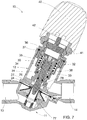
- the body or pin 70 of the secondary equipment 33 has below a conical tip 77, suitable for housing partially in the abovementioned orifice 26 formed in the base wall 27 of the upper valve body 12, in order to vary the span of passage of the fluid, and therefore the flow rate of the valve.
- the configuration of the conical tip 77 is such that in the position of maximum insertion in the orifice 26 (see Figure 7 ) it does not close completely the span of passage of the fluid.
- the pin 70 also has, at the base of the aforesaid conical tip 77, an annular raised part 78, suitable for abutting against an inner annular shoulder 79 of the main equipment 32, in order to determine an upper end of stroke position of the secondary equipment 33 with respect to the main equipment 32 (see Figure 3 ).
- the translation of the secondary equipment 33 with respect to the main equipment 32 is normally performed manually, removing the actuator 40 and the block 50, and acting for example with an Allen key (not shown) in a corresponding shaped hole 80 provided above the pin 70.
- the actuator 40 is shown at schematic level, and is mounted on the valve body, more specifically on said ring nut 36 by means of a screw attachment 41.
- actuator 40 is for example a small electric motor which goes to act with a pusher 42 on the rod 51 of the block 50 for the transmission of motion to the functional unit "Kv".
- pusher 42 is schematised with a stem which projects in a differentiated manner from the actuator 40 according to the working conditions of the valve, as will now be described.
- FIGS. 3 and 4 illustrate respectively a presetting wherein there is a maximum flow rate, i.e. minimum occlusion of the orifice 26, with the pin 70 of the secondary equipment in the position of upper end of stroke ( Figure 3 ); a presetting wherein there is an intermediate flow rate ( Figure 4 ); and a presetting wherein there is a minimum flow rate, determined by the maximum linear translation of the secondary equipment 33 with respect to the main equipment 32, wherein the abovementioned annular flange 72 of the secondary equipment abuts against the step 76 of the main equipment.
- the actuator 40 is actuated further making the pusher 42 project further and which, acting on the motion transmission rod 51, further lowers the assembly of the two items of equipment, bringing the conical bevel 61 in sealed abutment against the aforesaid conical hole 62 coaxial and external to the orifice 26 of regulation of the flow rate ( Figure 7 ). From what has been disclosed the advantages appear clear of the PICV valve according to the invention due to the doubling of the mobile equipment.
- the double mobile equipment structure allows, although maintaining the advantages present in the solution described in the prior art, separation of manual presetting of the maximum flow rate from modulation of the position of the regulation equipment: whatever the setting of the presetting starting from the position of maximum opening of the valve was, it will remain available to the actuator for the displacements necessary for the further reduction in the span of passage necessary for the modulating regulation again for the entire stroke provided in the design for the travel of the main equipment.
- the entire modulating regulation is distributed always over the entire length of the stroke available, therefore maintaining reduced to a minimum the influence of the mechanical tolerances of machining and assembly of the components.
- the modulating regulation will therefore be found to have the maximum possible effect also due to the strong reductions in the maximum flow rate preset.
- the component materials of the valve are preferably metals such as brass, bronze, steel and the like.
- ⁇ p unit suitable for maintaining constant the set flow rate of the valve independently of the fluctuations of the pressures, can obviously be shaped differently from what is illustrated in the accompanying drawings. Other interconnections may be provided between the two items of mobile equipment and between the latter and the valve body.
- the two mobile linear items of equipment 32 and 33 can work with pulling rather than pushing by the actuator 40, in which case the respective cut-offs, appropriately shaped, are placed below the respective orifices of passage of the fluid, rather than above as shown in the drawings, working therefore in favour of the flow, rather than in opposition.
- the presence of devices for indicating the degree of positioning of the cut-offs of the two items of equipment can also be provided, for example with the provision of graduated scales.
Landscapes
- Engineering & Computer Science (AREA)
- Physics & Mathematics (AREA)
- General Physics & Mathematics (AREA)
- Automation & Control Theory (AREA)
- Power Engineering (AREA)
- Fluid Mechanics (AREA)
- Lift Valve (AREA)
- Fluid-Driven Valves (AREA)
- Fluid-Pressure Circuits (AREA)
- Lubrication Of Internal Combustion Engines (AREA)
- Details Of Valves (AREA)
- Safety Valves (AREA)
- Flow Control (AREA)
Claims (11)
- Druckunabhängiges Durchflussregelventil (PICV), das dafür geeignet ist, in Hydraulikanlagen zwischen einer stromaufwärts gelegenen Fluideinlassleitung (13) und einer stromabwärts gelegenen Auslassleitung (14) angeordnet zu werden, wobei es eine erste Funktionseinheit (Kv), die zwischen der Einlassleitung (13) und der Auslassleitung (14) angeordnet ist, die eine mobile Apparatur (30) umfasst, die manuell oder mit Hilfe eines Stellantriebs (40) betätigt werden kann zum Einstellen und Modifizieren der Spannweite einer Durchgangsöffnung des Fluids und folglich des Ventildurchflusses, bis zu einem vollständigen Verschluss, und eine zweite Funktionseinheit (Δp), die dafür geeignet ist, den Differenzdruck (P2-P3) zwischen der stromaufwärts und der stromabwärts gelegenen Seite der ersten Einheit (Kv) und folglich den eingestellten Durchfluss des Ventils unabhängig von den Schwankungen des Drucks in der Hydraulikanlage konstant zu halten, umfasst,
wobei die mobile Apparatur (30) eine Hauptapparatur (32) umfasst, die integral eine sekundäre Apparatur (33) trägt und durch manuelle Betätigung der mit Hilfe des Stellantriebs (40) verschiebbar ist zum Modulieren des Durchflusses des Fluids von einem voreingestellten maximalen Durchfluss bis zu einem vollständigen Verschluss, dadurch gekennzeichnet, dass sich die sekundäre Apparatur (33) in Bezug auf die Hauptapparatur (32) linear verschieben kann zum Voreinstellen des maximalen Durchflusses des Ventils. - Ventil nach Anspruch 1, ferner dadurch gekennzeichnet, dass die Hauptapparatur (32) und die sekundäre Apparatur (33) koaxial zueinander sind und auf jeweilige koaxiale Öffnungen (62, 26) des Durchgangs des Fluids einwirken.
- Ventil nach Anspruch 2, wobei die Hauptapparatur (32) und die sekundäre Apparatur (33) mit Hilfe einer Gewindekupplung (71) integral hergestellt sind.
- Ventil nach einem der Ansprüche 2 oder 3, wobei elastische Mittel (38) bereitgestellt werden, die gegen die Wirkung des Stellantriebs (40) auf die Hauptapparatur (32) einwirken.
- Ventil nach einem der Ansprüche 2 bis 4, wobei die sekundäre Apparatur (33) innerhalb der Hauptapparatur (32) angeordnet ist.
- Ventil nach Anspruch 5, wobei die Hauptapparatur (32) in einer Umschließungshülle (35) untergebracht ist, wo die elastischen Mittel (38) angeordnet sind, die dazu neigen, die Hauptapparatur (32) zu dem Stellantrieb (40) hin zu schieben, wobei der Letztere durch Schub arbeitet, mit Hilfe einer Schubvorrichtung (42) und einer Übertragungsstange (51), welche die Bewegung auf die Hauptapparatur (32) übertragt, um die Apparaturelemente (32, 33) nahe an die Öffnungen (62, 26) zu bringen.
- Ventil nach Anspruch 6, wobei die sekundäre Apparatur (33) eine konische Spitze (77) hat, die auf eine solche Weise geformt ist, dass sie die entsprechende Öffnung (26) nicht vollständig verschließt, wenn sich die Apparaturelemente in der Hub-Endstellung befinden, während die Hauptapparatur (32) eine Stirnfläche (61) hat, die in Metall oder einem elastischen Material hergestellt ist, geeignet, um mit der Öffnung (62) in Wechselwirkung zu treten, um den Durchgang des Fluids zu verhindern, um so einen vollständigen Verschluss des Ventils zu bewirken.
- Ventil nach einem der Ansprüche 5 bis 7, wobei die sekundäre Apparatur (33), die in der Hauptapparatur (32) untergebracht ist, die Form eines zylindrischen Stiftes hat, der einen oberen ringförmigen Flansch (72) hat, der in einem erweiterten Saum (75) der Hauptapparatur (32) untergebracht und zum Anstoßen an eine Stufe (76) geeignet ist, die in der Letzteren geformt ist, in der unteren Hub-Endstellung, die den Voreinstellungszustand eines minimalen Durchflusses bestimmt, während an der Basis der konischen Spitze (77) ein ringförmiger Vorsprung (78) bereitgestellt wird, der geeignet ist zum Anstoßen an eine Stufe (79) der Hauptapparatur (32) in der oberen Hub-Endstellung der sekundären Apparatur, die dem Voreinstellungszustand eines maximalen Durchflusses entspricht.
- Ventil nach Anspruch 8, wobei die Außenfläche des Saums (75) die Form eines vieleckigen Prismas hat, geeignet zum freien axialen Gleiten in einem Sitz mit einer entsprechenden prismatischen Geometrie, die in einer Ringmutter (36) erhalten wird, aber zum Verhindern der verhältnismäßigen Drehung desselben, so dass, wenn die sekundäre Apparatur (33) aufgeschraubt oder abgeschraubt wird zum Einstellen des maximalen Durchflusses, die Hauptapparatur (32) am Drehen gehindert wird, was folglich ermöglicht, dass die Aufschraube-/Abschraubebewegung an der sekundären Apparatur (33) immer von dem verhältnismäßigen axialen Gleiten in Bezug auf die Hauptapparatur (32) gefolgt wird.
- Ventil nach einem der vorhergehenden Ansprüche, ferner dadurch gekennzeichnet, dass ein Gehäuse des Ventils ein unteres Ventilgehäuse (11) und ein oberes Ventilgehäuse (12), die integral miteinander verbunden sind, umfasst, wobei die zweite Funktionseinheit (Δp) in dem unteren Ventilgehäuse (11) untergebracht ist und die erste Funktionseinheit (Kv) in dem oberen Ventilgehäuse (12) untergebracht ist, in dessen Bodenwand (27) die Öffnungen (26, 62) geformt sind.
- Ventil nach Anspruch 10, wobei die zweite Funktionseinheit (Δp) einen röhrenförmigen Schieber (20) umfasst, der unterhalb der Öffnung (26) positioniert und in der Richtung dieser Öffnung (26) geschoben wird, ohne sie vollständig zu verschließen, durch die Wirkung einer Feder (28), und der röhrenförmige Schieber (20) in einer Kammer (C) untergebracht ist, die in eine untere Kammer (C1) und eine obere Kammer (C2) geteilt ist durch eine Membran (24), welche die Form einer kreisförmigen Krone hat, deren äußere Umfangskante durch das untere (11) und das obere (12) Ventilgehäuse blockiert wird und deren innere Kante an den röhrenförmigen Schieber (20) eingespannt ist, der in Axialrichtung beweglich ist zum Modifizieren einer Einlass-Spannweite des Fluids (23) in Abhängigkeit von den Drücken (P2, P3), die jeweils in der oberen Kammer (C2) beziehungsweise in der unteren Kammer (C 1) wirken, um den Differenzdruck zwischen (P2) und (P3) unter Kontrolle zu halten.
Applications Claiming Priority (2)
| Application Number | Priority Date | Filing Date | Title |
|---|---|---|---|
| IT002133A ITMI20132133A1 (it) | 2013-12-19 | 2013-12-19 | Valvola di bilanciamento dinamico per controllo della portata indipendente dalla pressione |
| PCT/EP2014/075001 WO2015090817A1 (en) | 2013-12-19 | 2014-11-19 | Dynamic balancing valve for control of flow rate independently of pressure |
Publications (2)
| Publication Number | Publication Date |
|---|---|
| EP3084545A1 EP3084545A1 (de) | 2016-10-26 |
| EP3084545B1 true EP3084545B1 (de) | 2017-11-29 |
Family
ID=50190549
Family Applications (1)
| Application Number | Title | Priority Date | Filing Date |
|---|---|---|---|
| EP14800053.2A Active EP3084545B1 (de) | 2013-12-19 | 2014-11-19 | Dynamisches ausgleichsventil zur steuerung des durchflusses unabhängig vom druck |
Country Status (7)
| Country | Link |
|---|---|
| US (1) | US10013001B2 (de) |
| EP (1) | EP3084545B1 (de) |
| CN (1) | CN105829986B (de) |
| DK (1) | DK3084545T3 (de) |
| IT (1) | ITMI20132133A1 (de) |
| SA (1) | SA516371296B1 (de) |
| WO (1) | WO2015090817A1 (de) |
Families Citing this family (5)
| Publication number | Priority date | Publication date | Assignee | Title |
|---|---|---|---|---|
| DK178871B1 (en) * | 2015-11-05 | 2017-04-10 | Danfoss As | Valve with detachable regulation unit |
| CN109009413B (zh) * | 2018-08-13 | 2024-02-06 | 北京安和加利尔科技有限公司 | 一种具有注液结构的内镜用高频电刀 |
| IT201900003433A1 (it) * | 2019-03-08 | 2020-09-08 | Giacomini Spa | Gruppo di regolazione a cartuccia e valvola idraulica con doppia scala di regolazione della portata. |
| NO346853B1 (no) * | 2021-06-23 | 2023-01-30 | Braathen Thor F | Et skap for kaldt og varmt forbruksvann til hus med nødvendige ventiler og fordelerrør |
| EP4625090A1 (de) * | 2024-03-28 | 2025-10-01 | Pittway Sarl | Turbinenfunktion in einem steuerventil |
Family Cites Families (19)
| Publication number | Priority date | Publication date | Assignee | Title |
|---|---|---|---|---|
| US2866477A (en) * | 1954-03-19 | 1958-12-30 | Crane Co | Combined throttle and stop valve |
| US3630228A (en) * | 1969-12-31 | 1971-12-28 | United Aircraft Corp | Water regulator and check valve for a jet engine |
| US4791956A (en) * | 1987-09-28 | 1988-12-20 | Asahi Yukizai Kogyo Co., Ltd. | Constant flow valve |
| DK160648B (da) * | 1988-08-05 | 1991-04-02 | Frese Armatur | Fremgangsmaade til regulering af et central- eller fjernvarmeanlaeg med en differenstrykventil og anlaeg til brug hertil |
| AU677159B2 (en) * | 1990-08-28 | 1997-04-17 | Tour & Andersson Ab | Combined control and regulating valve for liquids or gases |
| CN2382919Y (zh) * | 1999-07-30 | 2000-06-14 | 北京天箭星机电技术有限公司 | 恒流量调节阀 |
| DK174076B1 (da) * | 2000-01-21 | 2002-05-21 | Flowcon Int As | Reguleringsindsats til anbringelse i ventiler og ventilenhed |
| US6688319B2 (en) * | 2002-04-10 | 2004-02-10 | Flow Design, Inc. | Flow regulating control valve and method for regulating fluid flow |
| DE10323981B3 (de) * | 2003-05-27 | 2005-04-21 | Danfoss A/S | Heizungs-Ventilanordnung |
| SE528703C2 (sv) * | 2004-09-15 | 2007-01-30 | Tour & Andersson Ab | Anordning för flödesreglering av ett medium i ett värme-och kylsystem |
| DK176350B2 (da) * | 2005-06-23 | 2008-10-13 | Frese As | Reguleringsventil |
| WO2007127949A2 (en) * | 2006-04-27 | 2007-11-08 | Sko Flo Industries, Inc. | Flow control valve |
| US7621461B2 (en) * | 2006-08-18 | 2009-11-24 | Flow Design, Inc. | System and method for regulating heat transfer on a fluid by regulating the flow of the fluid |
| SE532137C2 (sv) * | 2006-10-04 | 2009-10-27 | Tour & Andersson Ab | Ventil med reglerfunktion |
| DE112008003909A5 (de) * | 2008-04-18 | 2011-04-07 | F.W. Oventrop Gmbh & Co. Kg | Armaturenkombination zur Regelung der Durchflussmenge oder des Differenzdruckes |
| US8596296B2 (en) * | 2008-04-30 | 2013-12-03 | Broen A/S | Regulation valve |
| DK177066B1 (da) * | 2008-05-05 | 2011-05-23 | Frese As | Reguleringsventil |
| SE533456C2 (sv) * | 2009-02-05 | 2010-10-05 | Tour & Andersson Ab | Ventil försedd med en delta p-funktion och en flödesbegränsningsfunktion |
| DE102009011506B4 (de) * | 2009-03-06 | 2013-05-02 | Oventrop Gmbh & Co. Kg | Durchflussregelventil für Heizungs- und Kühlanlagen |
-
2013
- 2013-12-19 IT IT002133A patent/ITMI20132133A1/it unknown
-
2014
- 2014-11-19 US US15/106,335 patent/US10013001B2/en active Active
- 2014-11-19 WO PCT/EP2014/075001 patent/WO2015090817A1/en not_active Ceased
- 2014-11-19 CN CN201480068909.9A patent/CN105829986B/zh active Active
- 2014-11-19 DK DK14800053.2T patent/DK3084545T3/en active
- 2014-11-19 EP EP14800053.2A patent/EP3084545B1/de active Active
-
2016
- 2016-06-12 SA SA516371296A patent/SA516371296B1/ar unknown
Also Published As
| Publication number | Publication date |
|---|---|
| CN105829986A (zh) | 2016-08-03 |
| EP3084545A1 (de) | 2016-10-26 |
| ITMI20132133A1 (it) | 2015-06-20 |
| WO2015090817A1 (en) | 2015-06-25 |
| DK3084545T3 (en) | 2018-03-05 |
| US10013001B2 (en) | 2018-07-03 |
| CN105829986B (zh) | 2018-12-07 |
| US20170003692A1 (en) | 2017-01-05 |
| SA516371296B1 (ar) | 2019-07-04 |
Similar Documents
| Publication | Publication Date | Title |
|---|---|---|
| EP3084545B1 (de) | Dynamisches ausgleichsventil zur steuerung des durchflusses unabhängig vom druck | |
| KR101690810B1 (ko) | 인-라인 압력 조절기 | |
| JP6449159B2 (ja) | 流体調整装置および流体流量制御装置のためのバランスポート制御アセンブリ | |
| EP3147594B1 (de) | Ventil für ein kühlsystem | |
| US9732866B2 (en) | Adjustable temperature regulated faucet | |
| CN203797073U (zh) | 紧急切断安全装置 | |
| US9494950B2 (en) | Pressure regulator | |
| CA1290643C (en) | Automatic pressurized reservoir bleed valve | |
| EP3309643B1 (de) | Druckunabhängiges regelventil | |
| US6843266B2 (en) | Regulator with erosion resistant seal assemblies | |
| RU2643113C2 (ru) | Входной контроль для симметричного входа | |
| KR101253666B1 (ko) | 유량 조절 밸브 | |
| US5507468A (en) | Integral bi-directional flow control valve | |
| EP3129660A1 (de) | Servoventil | |
| KR102132364B1 (ko) | 교번하는 시트 시스템을 가진 아마튜어 | |
| GB2582747A (en) | Device for controlling fluid flow | |
| US4237922A (en) | In-line flow control valve | |
| US20140326336A1 (en) | Valve, In Particular A Pressure Regulating Valve Or Pressure Limiting Valve | |
| US2725896A (en) | Valves | |
| EP3454160B1 (de) | Differenzdruckregelventil | |
| US3823729A (en) | Differential pressure monitoring valve | |
| EP2748468A1 (de) | Manuelle übersteuerungsvorrichtung für ein doppelschieberventil | |
| SU1138579A1 (ru) | Регул тор расхода |
Legal Events
| Date | Code | Title | Description |
|---|---|---|---|
| PUAI | Public reference made under article 153(3) epc to a published international application that has entered the european phase |
Free format text: ORIGINAL CODE: 0009012 |
|
| 17P | Request for examination filed |
Effective date: 20160608 |
|
| AK | Designated contracting states |
Kind code of ref document: A1 Designated state(s): AL AT BE BG CH CY CZ DE DK EE ES FI FR GB GR HR HU IE IS IT LI LT LU LV MC MK MT NL NO PL PT RO RS SE SI SK SM TR |
|
| AX | Request for extension of the european patent |
Extension state: BA ME |
|
| DAX | Request for extension of the european patent (deleted) | ||
| GRAP | Despatch of communication of intention to grant a patent |
Free format text: ORIGINAL CODE: EPIDOSNIGR1 |
|
| STAA | Information on the status of an ep patent application or granted ep patent |
Free format text: STATUS: GRANT OF PATENT IS INTENDED |
|
| RIC1 | Information provided on ipc code assigned before grant |
Ipc: G05D 7/01 20060101ALI20170808BHEP Ipc: G05D 7/00 20060101ALI20170808BHEP Ipc: G05D 7/06 20060101AFI20170808BHEP Ipc: G05D 16/06 20060101ALI20170808BHEP |
|
| INTG | Intention to grant announced |
Effective date: 20170913 |
|
| GRAS | Grant fee paid |
Free format text: ORIGINAL CODE: EPIDOSNIGR3 |
|
| GRAA | (expected) grant |
Free format text: ORIGINAL CODE: 0009210 |
|
| STAA | Information on the status of an ep patent application or granted ep patent |
Free format text: STATUS: THE PATENT HAS BEEN GRANTED |
|
| AK | Designated contracting states |
Kind code of ref document: B1 Designated state(s): AL AT BE BG CH CY CZ DE DK EE ES FI FR GB GR HR HU IE IS IT LI LT LU LV MC MK MT NL NO PL PT RO RS SE SI SK SM TR |
|
| REG | Reference to a national code |
Ref country code: CH Ref legal event code: EP |
|
| REG | Reference to a national code |
Ref country code: AT Ref legal event code: REF Ref document number: 950954 Country of ref document: AT Kind code of ref document: T Effective date: 20171215 |
|
| REG | Reference to a national code |
Ref country code: IE Ref legal event code: FG4D |
|
| REG | Reference to a national code |
Ref country code: DE Ref legal event code: R096 Ref document number: 602014018010 Country of ref document: DE |
|
| REG | Reference to a national code |
Ref country code: DK Ref legal event code: T3 Effective date: 20180226 |
|
| REG | Reference to a national code |
Ref country code: SE Ref legal event code: TRGR |
|
| REG | Reference to a national code |
Ref country code: NL Ref legal event code: MP Effective date: 20171129 |
|
| REG | Reference to a national code |
Ref country code: LT Ref legal event code: MG4D |
|
| REG | Reference to a national code |
Ref country code: AT Ref legal event code: MK05 Ref document number: 950954 Country of ref document: AT Kind code of ref document: T Effective date: 20171129 |
|
| PG25 | Lapsed in a contracting state [announced via postgrant information from national office to epo] |
Ref country code: LT Free format text: LAPSE BECAUSE OF FAILURE TO SUBMIT A TRANSLATION OF THE DESCRIPTION OR TO PAY THE FEE WITHIN THE PRESCRIBED TIME-LIMIT Effective date: 20171129 Ref country code: FI Free format text: LAPSE BECAUSE OF FAILURE TO SUBMIT A TRANSLATION OF THE DESCRIPTION OR TO PAY THE FEE WITHIN THE PRESCRIBED TIME-LIMIT Effective date: 20171129 Ref country code: ES Free format text: LAPSE BECAUSE OF FAILURE TO SUBMIT A TRANSLATION OF THE DESCRIPTION OR TO PAY THE FEE WITHIN THE PRESCRIBED TIME-LIMIT Effective date: 20171129 Ref country code: NO Free format text: LAPSE BECAUSE OF FAILURE TO SUBMIT A TRANSLATION OF THE DESCRIPTION OR TO PAY THE FEE WITHIN THE PRESCRIBED TIME-LIMIT Effective date: 20180228 |
|
| PG25 | Lapsed in a contracting state [announced via postgrant information from national office to epo] |
Ref country code: GR Free format text: LAPSE BECAUSE OF FAILURE TO SUBMIT A TRANSLATION OF THE DESCRIPTION OR TO PAY THE FEE WITHIN THE PRESCRIBED TIME-LIMIT Effective date: 20180301 Ref country code: HR Free format text: LAPSE BECAUSE OF FAILURE TO SUBMIT A TRANSLATION OF THE DESCRIPTION OR TO PAY THE FEE WITHIN THE PRESCRIBED TIME-LIMIT Effective date: 20171129 Ref country code: AT Free format text: LAPSE BECAUSE OF FAILURE TO SUBMIT A TRANSLATION OF THE DESCRIPTION OR TO PAY THE FEE WITHIN THE PRESCRIBED TIME-LIMIT Effective date: 20171129 Ref country code: LV Free format text: LAPSE BECAUSE OF FAILURE TO SUBMIT A TRANSLATION OF THE DESCRIPTION OR TO PAY THE FEE WITHIN THE PRESCRIBED TIME-LIMIT Effective date: 20171129 Ref country code: RS Free format text: LAPSE BECAUSE OF FAILURE TO SUBMIT A TRANSLATION OF THE DESCRIPTION OR TO PAY THE FEE WITHIN THE PRESCRIBED TIME-LIMIT Effective date: 20171129 Ref country code: BG Free format text: LAPSE BECAUSE OF FAILURE TO SUBMIT A TRANSLATION OF THE DESCRIPTION OR TO PAY THE FEE WITHIN THE PRESCRIBED TIME-LIMIT Effective date: 20180228 |
|
| PG25 | Lapsed in a contracting state [announced via postgrant information from national office to epo] |
Ref country code: NL Free format text: LAPSE BECAUSE OF FAILURE TO SUBMIT A TRANSLATION OF THE DESCRIPTION OR TO PAY THE FEE WITHIN THE PRESCRIBED TIME-LIMIT Effective date: 20171129 |
|
| PG25 | Lapsed in a contracting state [announced via postgrant information from national office to epo] |
Ref country code: SK Free format text: LAPSE BECAUSE OF FAILURE TO SUBMIT A TRANSLATION OF THE DESCRIPTION OR TO PAY THE FEE WITHIN THE PRESCRIBED TIME-LIMIT Effective date: 20171129 Ref country code: CZ Free format text: LAPSE BECAUSE OF FAILURE TO SUBMIT A TRANSLATION OF THE DESCRIPTION OR TO PAY THE FEE WITHIN THE PRESCRIBED TIME-LIMIT Effective date: 20171129 Ref country code: EE Free format text: LAPSE BECAUSE OF FAILURE TO SUBMIT A TRANSLATION OF THE DESCRIPTION OR TO PAY THE FEE WITHIN THE PRESCRIBED TIME-LIMIT Effective date: 20171129 Ref country code: CY Free format text: LAPSE BECAUSE OF FAILURE TO SUBMIT A TRANSLATION OF THE DESCRIPTION OR TO PAY THE FEE WITHIN THE PRESCRIBED TIME-LIMIT Effective date: 20171129 |
|
| REG | Reference to a national code |
Ref country code: DE Ref legal event code: R097 Ref document number: 602014018010 Country of ref document: DE |
|
| PG25 | Lapsed in a contracting state [announced via postgrant information from national office to epo] |
Ref country code: SM Free format text: LAPSE BECAUSE OF FAILURE TO SUBMIT A TRANSLATION OF THE DESCRIPTION OR TO PAY THE FEE WITHIN THE PRESCRIBED TIME-LIMIT Effective date: 20171129 Ref country code: PL Free format text: LAPSE BECAUSE OF FAILURE TO SUBMIT A TRANSLATION OF THE DESCRIPTION OR TO PAY THE FEE WITHIN THE PRESCRIBED TIME-LIMIT Effective date: 20171129 Ref country code: RO Free format text: LAPSE BECAUSE OF FAILURE TO SUBMIT A TRANSLATION OF THE DESCRIPTION OR TO PAY THE FEE WITHIN THE PRESCRIBED TIME-LIMIT Effective date: 20171129 |
|
| PLBE | No opposition filed within time limit |
Free format text: ORIGINAL CODE: 0009261 |
|
| STAA | Information on the status of an ep patent application or granted ep patent |
Free format text: STATUS: NO OPPOSITION FILED WITHIN TIME LIMIT |
|
| REG | Reference to a national code |
Ref country code: FR Ref legal event code: PLFP Year of fee payment: 5 |
|
| 26N | No opposition filed |
Effective date: 20180830 |
|
| PG25 | Lapsed in a contracting state [announced via postgrant information from national office to epo] |
Ref country code: SI Free format text: LAPSE BECAUSE OF FAILURE TO SUBMIT A TRANSLATION OF THE DESCRIPTION OR TO PAY THE FEE WITHIN THE PRESCRIBED TIME-LIMIT Effective date: 20171129 |
|
| REG | Reference to a national code |
Ref country code: CH Ref legal event code: PL |
|
| PG25 | Lapsed in a contracting state [announced via postgrant information from national office to epo] |
Ref country code: LU Free format text: LAPSE BECAUSE OF NON-PAYMENT OF DUE FEES Effective date: 20181119 Ref country code: MC Free format text: LAPSE BECAUSE OF FAILURE TO SUBMIT A TRANSLATION OF THE DESCRIPTION OR TO PAY THE FEE WITHIN THE PRESCRIBED TIME-LIMIT Effective date: 20171129 |
|
| REG | Reference to a national code |
Ref country code: BE Ref legal event code: MM Effective date: 20181130 |
|
| REG | Reference to a national code |
Ref country code: IE Ref legal event code: MM4A |
|
| PG25 | Lapsed in a contracting state [announced via postgrant information from national office to epo] |
Ref country code: LI Free format text: LAPSE BECAUSE OF NON-PAYMENT OF DUE FEES Effective date: 20181130 Ref country code: CH Free format text: LAPSE BECAUSE OF NON-PAYMENT OF DUE FEES Effective date: 20181130 |
|
| PG25 | Lapsed in a contracting state [announced via postgrant information from national office to epo] |
Ref country code: IE Free format text: LAPSE BECAUSE OF NON-PAYMENT OF DUE FEES Effective date: 20181119 |
|
| PG25 | Lapsed in a contracting state [announced via postgrant information from national office to epo] |
Ref country code: BE Free format text: LAPSE BECAUSE OF NON-PAYMENT OF DUE FEES Effective date: 20181130 |
|
| PG25 | Lapsed in a contracting state [announced via postgrant information from national office to epo] |
Ref country code: MT Free format text: LAPSE BECAUSE OF NON-PAYMENT OF DUE FEES Effective date: 20181119 |
|
| PG25 | Lapsed in a contracting state [announced via postgrant information from national office to epo] |
Ref country code: TR Free format text: LAPSE BECAUSE OF FAILURE TO SUBMIT A TRANSLATION OF THE DESCRIPTION OR TO PAY THE FEE WITHIN THE PRESCRIBED TIME-LIMIT Effective date: 20171129 |
|
| PG25 | Lapsed in a contracting state [announced via postgrant information from national office to epo] |
Ref country code: PT Free format text: LAPSE BECAUSE OF FAILURE TO SUBMIT A TRANSLATION OF THE DESCRIPTION OR TO PAY THE FEE WITHIN THE PRESCRIBED TIME-LIMIT Effective date: 20171129 |
|
| PG25 | Lapsed in a contracting state [announced via postgrant information from national office to epo] |
Ref country code: MK Free format text: LAPSE BECAUSE OF NON-PAYMENT OF DUE FEES Effective date: 20171129 Ref country code: HU Free format text: LAPSE BECAUSE OF FAILURE TO SUBMIT A TRANSLATION OF THE DESCRIPTION OR TO PAY THE FEE WITHIN THE PRESCRIBED TIME-LIMIT; INVALID AB INITIO Effective date: 20141119 |
|
| PG25 | Lapsed in a contracting state [announced via postgrant information from national office to epo] |
Ref country code: AL Free format text: LAPSE BECAUSE OF FAILURE TO SUBMIT A TRANSLATION OF THE DESCRIPTION OR TO PAY THE FEE WITHIN THE PRESCRIBED TIME-LIMIT Effective date: 20171129 Ref country code: IS Free format text: LAPSE BECAUSE OF FAILURE TO SUBMIT A TRANSLATION OF THE DESCRIPTION OR TO PAY THE FEE WITHIN THE PRESCRIBED TIME-LIMIT Effective date: 20180329 |
|
| P01 | Opt-out of the competence of the unified patent court (upc) registered |
Effective date: 20230526 |
|
| PGFP | Annual fee paid to national office [announced via postgrant information from national office to epo] |
Ref country code: DE Payment date: 20251127 Year of fee payment: 12 |
|
| PGFP | Annual fee paid to national office [announced via postgrant information from national office to epo] |
Ref country code: GB Payment date: 20251107 Year of fee payment: 12 |
|
| PGFP | Annual fee paid to national office [announced via postgrant information from national office to epo] |
Ref country code: DK Payment date: 20251125 Year of fee payment: 12 Ref country code: IT Payment date: 20251007 Year of fee payment: 12 |
|
| PGFP | Annual fee paid to national office [announced via postgrant information from national office to epo] |
Ref country code: FR Payment date: 20251126 Year of fee payment: 12 |
|
| PGFP | Annual fee paid to national office [announced via postgrant information from national office to epo] |
Ref country code: SE Payment date: 20251119 Year of fee payment: 12 |