EP3085253A1 - Machine de fabrication de tiges de l'industrie de traitement du tabac et procede de fabrication de tiges a plusieurs segments - Google Patents
Machine de fabrication de tiges de l'industrie de traitement du tabac et procede de fabrication de tiges a plusieurs segments Download PDFInfo
- Publication number
- EP3085253A1 EP3085253A1 EP16162770.8A EP16162770A EP3085253A1 EP 3085253 A1 EP3085253 A1 EP 3085253A1 EP 16162770 A EP16162770 A EP 16162770A EP 3085253 A1 EP3085253 A1 EP 3085253A1
- Authority
- EP
- European Patent Office
- Prior art keywords
- segments
- wrapping strip
- light
- strip
- machine according
- Prior art date
- Legal status (The legal status is an assumption and is not a legal conclusion. Google has not performed a legal analysis and makes no representation as to the accuracy of the status listed.)
- Granted
Links
Images

Classifications
-
- A—HUMAN NECESSITIES
- A24—TOBACCO; CIGARS; CIGARETTES; SIMULATED SMOKING DEVICES; SMOKERS' REQUISITES
- A24D—CIGARS; CIGARETTES; TOBACCO SMOKE FILTERS; MOUTHPIECES OF CIGARS OR CIGARETTES; MANUFACTURE OF TOBACCO SMOKE FILTERS OR MOUTHPIECES
- A24D3/00—Tobacco smoke filters, e.g. filter tips or filtering inserts; Filters specially adapted for simulated smoking devices; Mouthpieces of cigars or cigarettes
- A24D3/02—Manufacture of tobacco smoke filters
- A24D3/0295—Process control means
-
- A—HUMAN NECESSITIES
- A24—TOBACCO; CIGARS; CIGARETTES; SIMULATED SMOKING DEVICES; SMOKERS' REQUISITES
- A24D—CIGARS; CIGARETTES; TOBACCO SMOKE FILTERS; MOUTHPIECES OF CIGARS OR CIGARETTES; MANUFACTURE OF TOBACCO SMOKE FILTERS OR MOUTHPIECES
- A24D3/00—Tobacco smoke filters, e.g. filter tips or filtering inserts; Filters specially adapted for simulated smoking devices; Mouthpieces of cigars or cigarettes
- A24D3/02—Manufacture of tobacco smoke filters
- A24D3/0229—Filter rod forming processes
- A24D3/0233—Filter rod forming processes by means of a garniture
-
- A—HUMAN NECESSITIES
- A24—TOBACCO; CIGARS; CIGARETTES; SIMULATED SMOKING DEVICES; SMOKERS' REQUISITES
- A24D—CIGARS; CIGARETTES; TOBACCO SMOKE FILTERS; MOUTHPIECES OF CIGARS OR CIGARETTES; MANUFACTURE OF TOBACCO SMOKE FILTERS OR MOUTHPIECES
- A24D3/00—Tobacco smoke filters, e.g. filter tips or filtering inserts; Filters specially adapted for simulated smoking devices; Mouthpieces of cigars or cigarettes
- A24D3/02—Manufacture of tobacco smoke filters
- A24D3/0275—Manufacture of tobacco smoke filters for filters with special features
- A24D3/0287—Manufacture of tobacco smoke filters for filters with special features for composite filters
Definitions
- the present invention relates to a rod making machine of the tobacco processing industry for manufacturing multi-segment bars, comprising an endless driven format strip for conveying a wrapping strip laid on the format strip and a series of segments laid on the wrapping strip, an enclosing means for enclosing the segments with the wrapping strip, and a optical measuring device for detecting a property of the formed from the segments and the wrapping strip multi-segment strand.
- the present invention further relates to a method of manufacturing multi-segment bars of the tobacco processing industry.
- a stranding machine of the tobacco processing industry for producing multi-segment bars with an endless format belt and an enclosure device has long been known, see for example DE 27 36 871 A1 ,
- the object of the invention is to provide a stranding machine and a method in which a reliable optical detection of the segments is possible regardless of the nature of the wrapping material.
- the arrangement of the light exit in the conveying direction before the enclosure means an inspection of the segments before their wrapping with the wrapping strip on the still open strand is possible.
- a stranding machine with a format band it is surprising that such an arrangement is possible, since in the area before the wrapping of the segments only very little space is available and the field of view is usually covered by a hold-down for holding down the segments on the format ,
- Conventional optical sensors with corresponding optical elements can only partially reach all inspection points. Especially with position markings on a wrapping material strip, such as printing marks, and the mechanical boundary conditions in the format area, the angle of incidence is too shallow, i.e., too small. too little light passes from the object back to the receiving optics of the conventional sensor. A mechanical hold-down and the guidance of the still loose segments complicate the integration of conventional sensors.
- the light exit is formed by at least one light guide.
- optical fibers for example based on glass fiber
- the optical detection can be realized advantageously with minimal installation space. Due to the small design, a measuring distance and angle of incidence can be realized, which enables a reliable measurement without additional optical elements.
- the at least one light exit is preferably arranged in direct measuring relationship to the surface to be measured.
- direct measurement relationship means that the light emerging from the light exit falls directly onto the object to be examined (segment or wrapping strip) without optical elements arranged therebetween in the beam path, such as lenses, filters or the like.
- the measuring device is configured to carry out at least one punctiform and / or rectangular reflection measurement.
- Optical reflection measurements can be carried out with comparatively little effort, in comparison to optical transmission measurements, which do not always work reliably depending on the material investigated.
- a point measurement means that only the light intensity reflected by a point or light spot is determined, but a two-dimensional image consisting of a multiplicity of pixels does not have to be elaborately taken and evaluated, for example by means of a camera.
- the measuring device comprises a first light exit, which is arranged in measuring relation to the segment strand.
- a first light exit which is arranged in measuring relation to the segment strand.
- the measuring device comprises a second light exit, which is arranged in measuring relation to the wrapping strip.
- a second light exit which is arranged in measuring relation to the wrapping strip.
- the light exits are arranged at an angle in the range between 0 ° and 180 °, more preferably between 50 ° and 110 ° to each other. This advantageously enables a reliable detection of both the segments as well as marks or print marks on the wrapping paper with sufficiently steep angles of incidence of light.
- each light emission is generated by an associated transmitting optical fiber, wherein in particular each transmitting optical fiber, a corresponding receiving optical fiber can be assigned.
- the at least one light guide is advantageously held in a light guide head.
- the transmitting optical waveguide and the corresponding receiving optical waveguide are preferably arranged in a common outlet opening of the optical waveguide head.
- the light guide head is attached to a hold-down for holding down the segments. Since the hold-down is in a fixed spatial relationship to the segments, this is achieved in a simple manner that also the light guide head is in a fixed spatial relationship to the multi-segment strand. This is advantageous for a reliable and accurate optical measurement.
- the optical fiber head can be attached directly or indirectly, for example via a support element, to the hold-down device.
- the light guide head is guided through an opening in the hold-down, which can be particularly space-saving.
- the tubular or pin-shaped optical fiber head at an angle in the range between 0 ° and 90 °, more preferably between 30 ° and 60 ° inclined to the horizontal. This advantageously allows both a detection of the segments and the wrapping strip by means of a simply constructed optical fiber head.
- the invention is applicable to all extrusion machines of the tobacco processing industry for the manufacture of multi-segment bars.
- An advantageous application relates to a stranding machine for producing multi-segment filter rods.
- the invention can be used, in particular, for quality assurance with regard to defined lengths of the segments and / or possible cutting position monitoring or control.
- a relative position detection can be advantageously realized by a corresponding light guide arrangement, for example with contrast or color sensors.
- the stranding machine 10 is part of a machine for producing multi-segment filter rods 48, each consisting of a plurality of optically distinguishable filter rod segments 17.
- group forming device 12 groups of filter segments 17 are assembled and placed longitudinally by means of a loading device 33 on a withdrawn from a reel 37 and provided with a gluing device 38 with glue envelope strip 39.
- a loading device 33 on a withdrawn from a reel 37 and provided with a gluing device 38 with glue envelope strip 39.
- an initially open multisegment filter strand 41 is formed from the longitudinally juxtaposed filter segment groups.
- optically detectable markings or print marks 30 can be arranged on the Inside the wrapper strip 39.
- the wrapping strip 39 may be a wrapping paper strip.
- the wrapping strip 39 and the multi-segment filter strand 41 rest on a strand conveyor in the form of an endless format strip 42 driven by a drive 40.
- the format belt 42 guides the components 39, 41 through a format 45, or enclosing device 43, which completely wraps the wrapping strip 39 around the filter strand 41, due to the sizing, thus forming an endless closed multi-segment filter strand 44.
- This can pass through a seam plate 46, in which the adhesive seam is dried by means of heat input or cooling.
- individual multi-segment filter rods 48 are continuously cut off from the multi-segment filter strand 44 by means of a cutting device 47 and transferred to a downstream delivery conveyor.
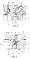
- the stranding machine 10 is shown in a cross section in the region between the loading device 33 and the enclosing device 43, in which the filter strand 41 is not yet enclosed by the wrapping paper.
- the format 45 has a longitudinal axial recess 49 for receiving and guiding the filter strand 41.
- the format tape 45 is placed in a U-shaped cross section on the format 45.
- the wrapping strip 39 is placed on the format strip 45 in a U-shaped cross-section, wherein the legs 39a of the wrapping strip 39 project upwards beyond the filter strand 41.
- a longitudinally axially extending hold-down 20 is provided in the Figures 2 and 4 is shown.
- the plate-shaped or strip-shaped holding-down device 20, for example, is arranged on the format 45 or in the recess 49 of the format 45 for holding down the segments 17 forming the filter strand 41.
- the hold-down 20 may be pivotable about a horizontal axis to make the format 45 accessible in case of failure.
- a light guide head 21 is provided which is part of an optical measuring device 19 (see FIG FIG. 4 ) for detecting the segments 17 in the filter strand 41 and / or for detecting marks 30 on the inside of the wrapping paper 39 is.
- the fiber optic head 21 is advantageously attached to the hold-down 20, so that due to the fixed spatial relationship between the filter strand 41 and the hold-down 20 also a fixed spatial relationship between the optical fiber head 21 and the filter strand 41 is made.
- the optical fiber head 21 For fixing the optical fiber head 21 to the plate-shaped holding-down device 20, it is possible, for example, to provide a holder 15 which is attached to the holding-down device 20 and extends perpendicular to it.
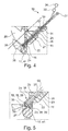
- the light guide head 21 is advantageously guided at an angle in the range between 0 ° and 90 °, more preferably between 30 ° and 60 °, even more preferably between 40 ° and 50 °, through an opening 16 in the hold-down 20 (see FIGS. 4, 5 ), which allows a particularly space-saving arrangement.
- the light guide head 21 comprises a, for example, pin-shaped or tubular housing 22, in which light guides 25, 31, 37, 50 to be explained later are arranged.
- the pin shape results in an optimal small design and high stability and protection for the light guides 25, 31, 37, 50.
- the hold-20 including optical fiber head 21 and the flexible light guides 25, 31, 37, 50 hinged to the side.
- the light guide head 21 For detecting differences, in particular color differences, on the shell side of the filter strand 41, which are caused in particular by transitions between the segments 17 in the filter strand 41, the light guide head 21 comprises a first light exit 23 (see FIG Figures 3 and 5 ), through which a directed on the shell side of the filter strand 41 first light beam or light cone 24 emerges.
- the first light beam 24 is preferably vertically, or substantially vertically in the range of + - 20 °, directed downward and arranged so that it preferably meets centrally of the segments 17 of the filter strand 41.
- a first transmission optical fiber 25 is provided (see FIG. 4 ), which extends from the first light outlet 23 in the interior of the housing 22 and is connected for example via a cable 26 to a remote light source 27.
- the light source 27 may be any suitable source of visible light, an infrared source and / or UV source.
- the first light exit 23 is formed by an end face of the first transmit light guide 25, which at a suitable angle preferably in the range between 30 ° and 60 °, more preferably in the range between 35 ° and 55 °, even more preferably in the range between 40 ° and is inclined 50 ° towards the measuring head axis.
- the light emerging from the first light exit 23 of the first transmission light guide 25 falls directly and directly, ie without interposed optical elements, such as lenses, filters, etc., onto the surface to be examined, here the lateral surface of the filter strand 41 or the segments 17. It is not excluded that the housing 22 has a transparent, the first light exit opening 29 occlusive exit window.
- the light reflected by the surface to be examined falls on a first light entrance 28, which may be arranged adjacent to the first light exit 23. It is thus a punctiform and / or rectangular reflection measurement.
- the first light outlet 23 and the first light inlet 28 are advantageously arranged together in one and the same outlet opening 29 of the measuring head 21 or of the measuring head housing 22.
- a first receiving optical fiber 31 is associated with the first light inlet 28, with which the reflected light entering the measuring head 21 through the first light inlet 28 is directed to a remote optical sensor 32, in particular in the region of the light source 27, in order to obtain a light from the Intensity of the reflected light dependent electrical signal to produce.
- the optical sensor 32 is suitably tuned to the measurement wavelength of the light source 27. It may preferably be a contrast or color sensor. A luminescence or infrared sensor can also be used according to the requirements. In principle, all sensor principles can be advantageously used, which can be physically combined with optical fibers or combined in other ways. By variable length of the light guides 25, 31, 37, 50, the sensor 32 can be installed appropriately at a suitable location.
- the light guide head 21 For detecting markings or print marks 30 on the inside of the wrapping strip 39, the light guide head 21 comprises a second light outlet 35 (see FIG Figures 3 and 5 ), through which a second light beam or light cone 36 directed onto the inside of the wrapping strip 39 exits.
- the second light beam 36 is preferably laterally directed approximately horizontally in the range of + - 20 ° and arranged so that it preferably strikes the wrapping strip 39 approximately perpendicularly.
- a second transmitting light guide 37 is provided (see FIG. 4 ), which extends from the second light exit 35 inside the housing 22 and is connected for example via the cable 26 to the light source 27 (or a suitable further light source).
- the second light exit 35 is formed by an end face of the second transmitting light guide 37, which at a suitable angle, preferably in the range between 30 ° and 60 °, on is preferably inclined in the range between 35 ° and 55 °, even more preferably in the range between 40 ° and 50 ° to the Meßkopfachse.
- the light exits 23, 35 and the light beams 24, 26 form an angle in the range between 50 ° and 110 °, preferably between 60 ° and 100 °, more preferably between 70 ° and 90 ° to each other.
- the light emerging from the second light exit 35 of the second transmitting lightguide 37 falls directly and immediately, i. Without intermediate optical elements, such as lenses, filters, etc., on the surface to be examined, here the inside of the wrapping strip 39.
- the housing 22 has a transparent, the second light exit opening 13 occlusive exit window.
- the second light exit 35 is advantageously arranged below the upper edge of the wrapping strip 39, which allows a spatially optimal measuring arrangement.
- the light reflected from the surface to be examined falls on a second light entrance 11, which may be arranged adjacent to the second light exit 35. It is also a punctiform and / or rectangular reflection measurement.
- the second light exit 35 and the second light entrance 11 are advantageously arranged together in one and the same outlet opening 13 of the light guide head 21 or of the housing 22.
- the second light entrance 11 is associated with a second receiving optical fiber 50, with which the reflected light entering the light guide head 21 through the second light entrance 11 is directed to the optical sensor 32 (or a suitable further sensor) to reflect the intensity of the reflected light Light dependent, preferably electrical signal to produce.
- the electrical signals are converted into a digital signal and transmitted to an electronic data processing device 34.
- the signals are evaluated in order to derive therefrom the relative position and / or length of the individual segments 17, and / or a position and / or width detection of an inner mark 30 on the wrapping strip 39, as actual values for downstream monitoring - and to determine synchronization tasks.
- the evaluation can be done for example by determining one or more rising or falling signal edges.
- process-dependent material processing for example, cutting position control of the cutting device 47, detection of the object or segment length and position control can then be controlled and carried out automatically and online in the production process.
- an (error) signal may be generated when the relative allocation of a segment 17 to an inner marker 30 on the wrapper strip 39 exceeds or falls below given limits.
- the error signal can advantageously be used for ejecting defective articles, issuing a warning to an operator and / or for a machine stop.
- the cone angle of the cone of rays of the light cone 24, 36 is preferably small, in particular smaller than 70 ° or 68 °, preferably smaller than 45 °, more preferably smaller than 30 ° and amounts to preferably 22 °.
- the shape of the light exits 23, 35 may vary and be, for example, round or angular.
- the light exits 23, 35 are preferably polished smooth and can therefore be easily cleaned, for example in Leimabsatz etc.
- the optical measuring device 19 comprises the light source 27, the optical fiber head 21, the optical fibers 25, 31, 37, 50 and the optical sensor 32.
- the optical fiber technology used makes it possible to use any geometrical holders and guides with one or more optical detection points as online measuring device 19 to realize.
- a light guide head 21 may also be provided a plurality of optical fiber heads.
- a light guide head for a pair of transmit-receive optical fibers may be provided in each case.
- a separate fiber optic head for each light guide is not excluded.
Landscapes
- Manufacturing Of Cigar And Cigarette Tobacco (AREA)
- Investigating Or Analysing Materials By Optical Means (AREA)
Priority Applications (1)
| Application Number | Priority Date | Filing Date | Title |
|---|---|---|---|
| PL16162770.8T PL3085253T5 (pl) | 2015-04-24 | 2016-03-30 | Maszyna do wytwarzania kabli przemysłu przetwórstwa tytoniu i sposób wytwarzania sztabek wielosegmentowych |
Applications Claiming Priority (1)
| Application Number | Priority Date | Filing Date | Title |
|---|---|---|---|
| DE102015106347.6A DE102015106347A1 (de) | 2015-04-24 | 2015-04-24 | Strangmaschine der Tabak verarbeitenden Industrie und Verfahren zum Herstellen von Multisegmentstäben |
Publications (3)
| Publication Number | Publication Date |
|---|---|
| EP3085253A1 true EP3085253A1 (fr) | 2016-10-26 |
| EP3085253B1 EP3085253B1 (fr) | 2018-05-02 |
| EP3085253B2 EP3085253B2 (fr) | 2025-06-25 |
Family
ID=55640638
Family Applications (1)
| Application Number | Title | Priority Date | Filing Date |
|---|---|---|---|
| EP16162770.8A Active EP3085253B2 (fr) | 2015-04-24 | 2016-03-30 | Machine de fabrication de tiges de l'industrie de traitement du tabac et procede de fabrication de tiges a plusieurs segments |
Country Status (4)
| Country | Link |
|---|---|
| EP (1) | EP3085253B2 (fr) |
| CN (1) | CN106063586B (fr) |
| DE (1) | DE102015106347A1 (fr) |
| PL (1) | PL3085253T5 (fr) |
Cited By (2)
| Publication number | Priority date | Publication date | Assignee | Title |
|---|---|---|---|---|
| WO2019097428A1 (fr) * | 2017-11-14 | 2019-05-23 | G.D Società per Azioni | Unité et procédé d'inspection d'un groupe de parties d'articles de l'industrie du tabac |
| CN114747800A (zh) * | 2022-02-28 | 2022-07-15 | 浙江中烟工业有限责任公司 | 醋酸纤维丝束拼接段检测方法及装置 |
Citations (5)
| Publication number | Priority date | Publication date | Assignee | Title |
|---|---|---|---|---|
| DE2736871A1 (de) | 1977-08-16 | 1979-03-01 | Hauni Werke Koerber & Co Kg | Anordnung zum ueberwachen der arbeitsweise einer filterstrangherstellmaschine |
| US20070068540A1 (en) * | 2005-09-23 | 2007-03-29 | Thomas Timothy F | Equipment for insertion of objects into smoking articles |
| EP1913824A1 (fr) | 2006-10-18 | 2008-04-23 | G.D. S.p.A | Machine de fabrication de filtres composites |
| DE102009041319A1 (de) * | 2009-09-15 | 2011-03-24 | Hauni Maschinenbau Ag | Maschine zur Herstellung und Verfahren zum Herstellen von Multisegmentfiltern der Tabak verarbeitenden Industrie |
| EP2628399A1 (fr) * | 2009-09-15 | 2013-08-21 | HAUNI Maschinenbau AG | Tambour de transfert de l'industrie de traitement du tabac |
Family Cites Families (21)
| Publication number | Priority date | Publication date | Assignee | Title |
|---|---|---|---|---|
| CH627119A5 (fr) * | 1977-10-19 | 1981-12-31 | Baumgartner Papiers Sa | |
| DE3806320A1 (de) * | 1988-02-27 | 1989-09-07 | Hauni Werke Koerber & Co Kg | Verfahren und vorrichtung zum ueberwachen der geometrischen abmessungen von strang- oder stabfoermigen erzeugnissen der tabakverarbeitenden industrie |
| US6020969A (en) * | 1997-07-11 | 2000-02-01 | Philip Morris Incorporated | Cigarette making machine including band inspection |
| JP3372193B2 (ja) | 1997-08-20 | 2003-01-27 | 日本たばこ産業株式会社 | シガレット製造装置 |
| US6213128B1 (en) | 1999-06-04 | 2001-04-10 | Philip Morris Incorporated | Apparatus and method for making and inspecting multi-component wrapped article |
| EP1479305A1 (fr) * | 2002-02-27 | 2004-11-24 | Japan Tobacco Inc. | Appareil recepteur d'elements batonnets |
| JP2004024132A (ja) * | 2002-06-26 | 2004-01-29 | Japan Tobacco Inc | フィルタシガレット検査装置 |
| AU2003253235A1 (en) † | 2002-08-19 | 2004-03-03 | Green Vision Systems Ltd. | Electro-optically inspecting a longitudinally moving rod of material |
| US7448991B2 (en) | 2002-11-14 | 2008-11-11 | Philip Morris Usa Inc. | Process and system for monitoring a continuous element being incorporated within a cigarette filter |
| US6952257B2 (en) † | 2003-06-13 | 2005-10-04 | Philip Morris Usa Inc. | Inspection station |
| CN2712094Y (zh) * | 2003-09-15 | 2005-07-27 | 北京清大科技股份有限公司 | 条烟缺包在线检测装置 |
| DE10358670A1 (de) * | 2003-12-12 | 2005-07-07 | Focke & Co.(Gmbh & Co. Kg) | Verfahren und Vorrichtung zum Prüfen der Oberfläche eines bewegten Materialstrangs der tabakverarbeitenden Industrie |
| DE102005046581A1 (de) * | 2005-09-28 | 2007-03-29 | Hauni Maschinenbau Ag | Einrichtung und Verfahren zum Messen von Eigenschaften von Multisegmentfiltern oder Zusammenstellungen von Filtersegmenten |
| ZA200901679B (en) * | 2009-03-09 | 2015-08-26 | Tobacco Res And Development Institute (Pty) Ltd | Apparatus for introducing objects into filter rod material |
| DE202009012142U1 (de) † | 2009-09-07 | 2011-02-03 | Sick Ag | Optoelektronischer Sensor zur Streifenerkennung |
| PL217430B1 (pl) * | 2010-05-06 | 2014-07-31 | Int Tobacco Machinery Poland | Sposób ustalania wzajemnego położenia segmentów filtrowych na elemencie nośnym zespołu grupującego w procesie wytwarzania filtrów wielosegmentowych |
| DE102011113704A1 (de) * | 2011-08-02 | 2013-02-07 | Focke & Co. (Gmbh & Co. Kg) | Verfahren und Vorrichtung zur optischen Prüfung von bei der Herstellung und/oder Verpackung von Zigaretten zu prüfenden Objekten |
| DE102011082178A1 (de) * | 2011-09-06 | 2013-03-07 | Hauni Maschinenbau Ag | Optische Inspektion von stabförmigen Artikeln der Tabak verarbeitenden Industrie |
| DE102012224089A1 (de) * | 2012-12-20 | 2014-06-26 | Hauni Maschinenbau Ag | Messanordnung und Messverfahren für ein Filterstabsegment in der Tabak verarbeitenden Industrie, Maschine zum Herstellen von Filterstäben, Maschine und Anlage zur Herstellung eines Multisegmentfilterprodukts |
| CN103005709B (zh) * | 2012-12-28 | 2014-04-16 | 龙岩烟草工业有限责任公司 | 一种滤棒成型机的丝束拼接头检测剔除方法及装置 |
| CN103884717B (zh) * | 2014-04-03 | 2016-03-23 | 四川三联卷烟材料有限公司 | 一种自动测试特种滤棒截面特征参数的装置及测量方法 |
-
2015
- 2015-04-24 DE DE102015106347.6A patent/DE102015106347A1/de not_active Ceased
-
2016
- 2016-03-30 PL PL16162770.8T patent/PL3085253T5/pl unknown
- 2016-03-30 EP EP16162770.8A patent/EP3085253B2/fr active Active
- 2016-04-25 CN CN201610258993.1A patent/CN106063586B/zh active Active
Patent Citations (5)
| Publication number | Priority date | Publication date | Assignee | Title |
|---|---|---|---|---|
| DE2736871A1 (de) | 1977-08-16 | 1979-03-01 | Hauni Werke Koerber & Co Kg | Anordnung zum ueberwachen der arbeitsweise einer filterstrangherstellmaschine |
| US20070068540A1 (en) * | 2005-09-23 | 2007-03-29 | Thomas Timothy F | Equipment for insertion of objects into smoking articles |
| EP1913824A1 (fr) | 2006-10-18 | 2008-04-23 | G.D. S.p.A | Machine de fabrication de filtres composites |
| DE102009041319A1 (de) * | 2009-09-15 | 2011-03-24 | Hauni Maschinenbau Ag | Maschine zur Herstellung und Verfahren zum Herstellen von Multisegmentfiltern der Tabak verarbeitenden Industrie |
| EP2628399A1 (fr) * | 2009-09-15 | 2013-08-21 | HAUNI Maschinenbau AG | Tambour de transfert de l'industrie de traitement du tabac |
Cited By (2)
| Publication number | Priority date | Publication date | Assignee | Title |
|---|---|---|---|---|
| WO2019097428A1 (fr) * | 2017-11-14 | 2019-05-23 | G.D Società per Azioni | Unité et procédé d'inspection d'un groupe de parties d'articles de l'industrie du tabac |
| CN114747800A (zh) * | 2022-02-28 | 2022-07-15 | 浙江中烟工业有限责任公司 | 醋酸纤维丝束拼接段检测方法及装置 |
Also Published As
| Publication number | Publication date |
|---|---|
| DE102015106347A1 (de) | 2016-10-27 |
| PL3085253T5 (pl) | 2025-09-08 |
| PL3085253T3 (pl) | 2018-10-31 |
| EP3085253B2 (fr) | 2025-06-25 |
| EP3085253B1 (fr) | 2018-05-02 |
| CN106063586B (zh) | 2020-08-07 |
| CN106063586A (zh) | 2016-11-02 |
Similar Documents
| Publication | Publication Date | Title |
|---|---|---|
| EP1397961B1 (fr) | Procédé et installation pour la mesure de la longueur et du diamètre de tiges de filtre | |
| DE2732520C3 (de) | Einrichtung zur Überprüfung eines Stranges | |
| EP2918180B2 (fr) | Contrôle optique d'articles en forme de tige de l'industrie de traitement du tabac | |
| DE3628088C2 (fr) | ||
| EP1702524A1 (fr) | Détection des inhomogénéités dans une tige de filtre | |
| EP2769632B2 (fr) | Procédé de mesure et dispositif de mesure pour l'enregistrement de la position d'un objet dans une tige de filtre transportée en direction axiale longitudinale et machine de l'industrie de traitement du tabac | |
| DE3437580A1 (de) | Vorrichtung zum optischen pruefen eines zigarettenstrangs | |
| EP1655599B1 (fr) | Détecteur de fil | |
| EP1557100B1 (fr) | Inspection d'une tige de filtre | |
| EP3085253B1 (fr) | Machine de fabrication de tiges de l'industrie de traitement du tabac et procédé de fabrication de tiges a plusieurs segments | |
| DE202005007089U1 (de) | Sensoranordnung zur optischen Kantendetektierung einer Ware | |
| EP1445576A1 (fr) | Procédé et dispositif pour la mesure du diamètre d'un object en barre, en particulier de l'industrie du tabac | |
| DE19850335B4 (de) | Vorrichtung zum Erfassen von Eigenschaften einer in Längsrichtung transportierten Warenbahn | |
| EP3015851B1 (fr) | Tete d'application, dispositif d'application de fibre et procede | |
| DE3336659C2 (de) | Meßgerät zum Bestimmen des Profils des Feuchtigkeitsgehalts einer Materialbahn quer zu ihrer Laufrichtung | |
| EP1479303B1 (fr) | Appareil pour mesurer le diamètre d'un article en forme de tige, notamment de l'industrie du tabac | |
| EP4106557B1 (fr) | Procédé et dispositif d'examen de produits en forme de tige de l'industrie des cigarettes | |
| DE3834478A1 (de) | Verfahren zur messung der anzahl von titerungleichmaessigkeiten sowie vorrichtung zur durchfuehrung des verfahrens | |
| DE102004049879A1 (de) | Vorrichtung und Verfahren zum Messen des Durchmessers eines stabförmigen Gegenstandes insbesondere der Tabak verarbeitenden Industrie | |
| EP1709431A2 (fr) | Procede et dispositif de surveillance optique d'un faisceau de fibres qui chemine | |
| DE19816359A1 (de) | Fasersensor zum Erkennen von Oberflächenstrukturen | |
| DE102022121928A1 (de) | Verfahren bzw. System zum Analysieren von Objekten | |
| EP0737857A2 (fr) | Dispositif de contrÔle optique des irrégularités dans un fil | |
| DE102005025121B3 (de) | Verfahren zum Herstellen eines Bandes mit mehreren parallel verlaufenden Lichtleitern | |
| EP1518469B1 (fr) | Procédé et appareil pour l'investigation d'une tige de matériau de l'industrie du tabac |
Legal Events
| Date | Code | Title | Description |
|---|---|---|---|
| PUAI | Public reference made under article 153(3) epc to a published international application that has entered the european phase |
Free format text: ORIGINAL CODE: 0009012 |
|
| AK | Designated contracting states |
Kind code of ref document: A1 Designated state(s): AL AT BE BG CH CY CZ DE DK EE ES FI FR GB GR HR HU IE IS IT LI LT LU LV MC MK MT NL NO PL PT RO RS SE SI SK SM TR |
|
| AX | Request for extension of the european patent |
Extension state: BA ME |
|
| STAA | Information on the status of an ep patent application or granted ep patent |
Free format text: STATUS: REQUEST FOR EXAMINATION WAS MADE |
|
| 17P | Request for examination filed |
Effective date: 20170410 |
|
| RBV | Designated contracting states (corrected) |
Designated state(s): AL AT BE BG CH CY CZ DE DK EE ES FI FR GB GR HR HU IE IS IT LI LT LU LV MC MK MT NL NO PL PT RO RS SE SI SK SM TR |
|
| RIN1 | Information on inventor provided before grant (corrected) |
Inventor name: JONAT, ILMAR Inventor name: SACHER, DIRK |
|
| GRAP | Despatch of communication of intention to grant a patent |
Free format text: ORIGINAL CODE: EPIDOSNIGR1 |
|
| STAA | Information on the status of an ep patent application or granted ep patent |
Free format text: STATUS: GRANT OF PATENT IS INTENDED |
|
| INTG | Intention to grant announced |
Effective date: 20171106 |
|
| GRAS | Grant fee paid |
Free format text: ORIGINAL CODE: EPIDOSNIGR3 |
|
| GRAA | (expected) grant |
Free format text: ORIGINAL CODE: 0009210 |
|
| STAA | Information on the status of an ep patent application or granted ep patent |
Free format text: STATUS: THE PATENT HAS BEEN GRANTED |
|
| AK | Designated contracting states |
Kind code of ref document: B1 Designated state(s): AL AT BE BG CH CY CZ DE DK EE ES FI FR GB GR HR HU IE IS IT LI LT LU LV MC MK MT NL NO PL PT RO RS SE SI SK SM TR |
|
| REG | Reference to a national code |
Ref country code: GB Ref legal event code: FG4D Free format text: NOT ENGLISH |
|
| REG | Reference to a national code |
Ref country code: CH Ref legal event code: EP Ref country code: AT Ref legal event code: REF Ref document number: 994284 Country of ref document: AT Kind code of ref document: T Effective date: 20180515 |
|
| REG | Reference to a national code |
Ref country code: DE Ref legal event code: R096 Ref document number: 502016000950 Country of ref document: DE Ref country code: IE Ref legal event code: FG4D Free format text: LANGUAGE OF EP DOCUMENT: GERMAN |
|
| REG | Reference to a national code |
Ref country code: NL Ref legal event code: FP |
|
| REG | Reference to a national code |
Ref country code: LT Ref legal event code: MG4D |
|
| PG25 | Lapsed in a contracting state [announced via postgrant information from national office to epo] |
Ref country code: BG Free format text: LAPSE BECAUSE OF FAILURE TO SUBMIT A TRANSLATION OF THE DESCRIPTION OR TO PAY THE FEE WITHIN THE PRESCRIBED TIME-LIMIT Effective date: 20180802 Ref country code: NO Free format text: LAPSE BECAUSE OF FAILURE TO SUBMIT A TRANSLATION OF THE DESCRIPTION OR TO PAY THE FEE WITHIN THE PRESCRIBED TIME-LIMIT Effective date: 20180802 Ref country code: FI Free format text: LAPSE BECAUSE OF FAILURE TO SUBMIT A TRANSLATION OF THE DESCRIPTION OR TO PAY THE FEE WITHIN THE PRESCRIBED TIME-LIMIT Effective date: 20180502 Ref country code: SE Free format text: LAPSE BECAUSE OF FAILURE TO SUBMIT A TRANSLATION OF THE DESCRIPTION OR TO PAY THE FEE WITHIN THE PRESCRIBED TIME-LIMIT Effective date: 20180502 Ref country code: ES Free format text: LAPSE BECAUSE OF FAILURE TO SUBMIT A TRANSLATION OF THE DESCRIPTION OR TO PAY THE FEE WITHIN THE PRESCRIBED TIME-LIMIT Effective date: 20180502 Ref country code: LT Free format text: LAPSE BECAUSE OF FAILURE TO SUBMIT A TRANSLATION OF THE DESCRIPTION OR TO PAY THE FEE WITHIN THE PRESCRIBED TIME-LIMIT Effective date: 20180502 |
|
| PG25 | Lapsed in a contracting state [announced via postgrant information from national office to epo] |
Ref country code: LV Free format text: LAPSE BECAUSE OF FAILURE TO SUBMIT A TRANSLATION OF THE DESCRIPTION OR TO PAY THE FEE WITHIN THE PRESCRIBED TIME-LIMIT Effective date: 20180502 Ref country code: HR Free format text: LAPSE BECAUSE OF FAILURE TO SUBMIT A TRANSLATION OF THE DESCRIPTION OR TO PAY THE FEE WITHIN THE PRESCRIBED TIME-LIMIT Effective date: 20180502 Ref country code: GR Free format text: LAPSE BECAUSE OF FAILURE TO SUBMIT A TRANSLATION OF THE DESCRIPTION OR TO PAY THE FEE WITHIN THE PRESCRIBED TIME-LIMIT Effective date: 20180803 Ref country code: RS Free format text: LAPSE BECAUSE OF FAILURE TO SUBMIT A TRANSLATION OF THE DESCRIPTION OR TO PAY THE FEE WITHIN THE PRESCRIBED TIME-LIMIT Effective date: 20180502 |
|
| PG25 | Lapsed in a contracting state [announced via postgrant information from national office to epo] |
Ref country code: EE Free format text: LAPSE BECAUSE OF FAILURE TO SUBMIT A TRANSLATION OF THE DESCRIPTION OR TO PAY THE FEE WITHIN THE PRESCRIBED TIME-LIMIT Effective date: 20180502 Ref country code: DK Free format text: LAPSE BECAUSE OF FAILURE TO SUBMIT A TRANSLATION OF THE DESCRIPTION OR TO PAY THE FEE WITHIN THE PRESCRIBED TIME-LIMIT Effective date: 20180502 Ref country code: RO Free format text: LAPSE BECAUSE OF FAILURE TO SUBMIT A TRANSLATION OF THE DESCRIPTION OR TO PAY THE FEE WITHIN THE PRESCRIBED TIME-LIMIT Effective date: 20180502 Ref country code: CZ Free format text: LAPSE BECAUSE OF FAILURE TO SUBMIT A TRANSLATION OF THE DESCRIPTION OR TO PAY THE FEE WITHIN THE PRESCRIBED TIME-LIMIT Effective date: 20180502 Ref country code: SK Free format text: LAPSE BECAUSE OF FAILURE TO SUBMIT A TRANSLATION OF THE DESCRIPTION OR TO PAY THE FEE WITHIN THE PRESCRIBED TIME-LIMIT Effective date: 20180502 |
|
| REG | Reference to a national code |
Ref country code: DE Ref legal event code: R026 Ref document number: 502016000950 Country of ref document: DE |
|
| PLBI | Opposition filed |
Free format text: ORIGINAL CODE: 0009260 |
|
| PLAX | Notice of opposition and request to file observation + time limit sent |
Free format text: ORIGINAL CODE: EPIDOSNOBS2 |
|
| PG25 | Lapsed in a contracting state [announced via postgrant information from national office to epo] |
Ref country code: SM Free format text: LAPSE BECAUSE OF FAILURE TO SUBMIT A TRANSLATION OF THE DESCRIPTION OR TO PAY THE FEE WITHIN THE PRESCRIBED TIME-LIMIT Effective date: 20180502 |
|
| 26 | Opposition filed |
Opponent name: G.D S.P.A. Effective date: 20190201 |
|
| PG25 | Lapsed in a contracting state [announced via postgrant information from national office to epo] |
Ref country code: SI Free format text: LAPSE BECAUSE OF FAILURE TO SUBMIT A TRANSLATION OF THE DESCRIPTION OR TO PAY THE FEE WITHIN THE PRESCRIBED TIME-LIMIT Effective date: 20180502 |
|
| PLBB | Reply of patent proprietor to notice(s) of opposition received |
Free format text: ORIGINAL CODE: EPIDOSNOBS3 |
|
| PG25 | Lapsed in a contracting state [announced via postgrant information from national office to epo] |
Ref country code: MC Free format text: LAPSE BECAUSE OF FAILURE TO SUBMIT A TRANSLATION OF THE DESCRIPTION OR TO PAY THE FEE WITHIN THE PRESCRIBED TIME-LIMIT Effective date: 20180502 |
|
| REG | Reference to a national code |
Ref country code: CH Ref legal event code: PL |
|
| PG25 | Lapsed in a contracting state [announced via postgrant information from national office to epo] |
Ref country code: LU Free format text: LAPSE BECAUSE OF NON-PAYMENT OF DUE FEES Effective date: 20190330 Ref country code: AL Free format text: LAPSE BECAUSE OF FAILURE TO SUBMIT A TRANSLATION OF THE DESCRIPTION OR TO PAY THE FEE WITHIN THE PRESCRIBED TIME-LIMIT Effective date: 20180502 |
|
| REG | Reference to a national code |
Ref country code: BE Ref legal event code: MM Effective date: 20190331 |
|
| PG25 | Lapsed in a contracting state [announced via postgrant information from national office to epo] |
Ref country code: CH Free format text: LAPSE BECAUSE OF NON-PAYMENT OF DUE FEES Effective date: 20190331 Ref country code: LI Free format text: LAPSE BECAUSE OF NON-PAYMENT OF DUE FEES Effective date: 20190331 Ref country code: IE Free format text: LAPSE BECAUSE OF NON-PAYMENT OF DUE FEES Effective date: 20190330 |
|
| PG25 | Lapsed in a contracting state [announced via postgrant information from national office to epo] |
Ref country code: FR Free format text: LAPSE BECAUSE OF NON-PAYMENT OF DUE FEES Effective date: 20190331 Ref country code: BE Free format text: LAPSE BECAUSE OF NON-PAYMENT OF DUE FEES Effective date: 20190331 |
|
| PG25 | Lapsed in a contracting state [announced via postgrant information from national office to epo] |
Ref country code: TR Free format text: LAPSE BECAUSE OF FAILURE TO SUBMIT A TRANSLATION OF THE DESCRIPTION OR TO PAY THE FEE WITHIN THE PRESCRIBED TIME-LIMIT Effective date: 20180502 |
|
| PG25 | Lapsed in a contracting state [announced via postgrant information from national office to epo] |
Ref country code: MT Free format text: LAPSE BECAUSE OF FAILURE TO SUBMIT A TRANSLATION OF THE DESCRIPTION OR TO PAY THE FEE WITHIN THE PRESCRIBED TIME-LIMIT Effective date: 20180502 Ref country code: PT Free format text: LAPSE BECAUSE OF FAILURE TO SUBMIT A TRANSLATION OF THE DESCRIPTION OR TO PAY THE FEE WITHIN THE PRESCRIBED TIME-LIMIT Effective date: 20180903 |
|
| PG25 | Lapsed in a contracting state [announced via postgrant information from national office to epo] |
Ref country code: CY Free format text: LAPSE BECAUSE OF FAILURE TO SUBMIT A TRANSLATION OF THE DESCRIPTION OR TO PAY THE FEE WITHIN THE PRESCRIBED TIME-LIMIT Effective date: 20180502 |
|
| PG25 | Lapsed in a contracting state [announced via postgrant information from national office to epo] |
Ref country code: IS Free format text: LAPSE BECAUSE OF FAILURE TO SUBMIT A TRANSLATION OF THE DESCRIPTION OR TO PAY THE FEE WITHIN THE PRESCRIBED TIME-LIMIT Effective date: 20180902 |
|
| PG25 | Lapsed in a contracting state [announced via postgrant information from national office to epo] |
Ref country code: HU Free format text: LAPSE BECAUSE OF FAILURE TO SUBMIT A TRANSLATION OF THE DESCRIPTION OR TO PAY THE FEE WITHIN THE PRESCRIBED TIME-LIMIT; INVALID AB INITIO Effective date: 20160330 |
|
| APBM | Appeal reference recorded |
Free format text: ORIGINAL CODE: EPIDOSNREFNO |
|
| APBP | Date of receipt of notice of appeal recorded |
Free format text: ORIGINAL CODE: EPIDOSNNOA2O |
|
| APAH | Appeal reference modified |
Free format text: ORIGINAL CODE: EPIDOSCREFNO |
|
| APBQ | Date of receipt of statement of grounds of appeal recorded |
Free format text: ORIGINAL CODE: EPIDOSNNOA3O |
|
| REG | Reference to a national code |
Ref country code: AT Ref legal event code: MM01 Ref document number: 994284 Country of ref document: AT Kind code of ref document: T Effective date: 20210330 |
|
| PG25 | Lapsed in a contracting state [announced via postgrant information from national office to epo] |
Ref country code: MK Free format text: LAPSE BECAUSE OF FAILURE TO SUBMIT A TRANSLATION OF THE DESCRIPTION OR TO PAY THE FEE WITHIN THE PRESCRIBED TIME-LIMIT Effective date: 20180502 |
|
| PG25 | Lapsed in a contracting state [announced via postgrant information from national office to epo] |
Ref country code: AT Free format text: LAPSE BECAUSE OF NON-PAYMENT OF DUE FEES Effective date: 20210330 |
|
| REG | Reference to a national code |
Ref country code: DE Ref legal event code: R081 Ref document number: 502016000950 Country of ref document: DE Owner name: KOERBER TECHNOLOGIES GMBH, DE Free format text: FORMER OWNER: HAUNI MASCHINENBAU GMBH, 21033 HAMBURG, DE |
|
| REG | Reference to a national code |
Ref country code: NL Ref legal event code: HC Owner name: KOERBER TECHNOLOGIES GMBH; DE Free format text: DETAILS ASSIGNMENT: CHANGE OF OWNER(S), CHANGE OF OWNER(S) NAME; FORMER OWNER NAME: HAUNI MASCHINENBAU GMBH Effective date: 20221031 |
|
| RAP4 | Party data changed (patent owner data changed or rights of a patent transferred) |
Owner name: KOERBER TECHNOLOGIES GMBH |
|
| P01 | Opt-out of the competence of the unified patent court (upc) registered |
Effective date: 20230616 |
|
| APBU | Appeal procedure closed |
Free format text: ORIGINAL CODE: EPIDOSNNOA9O |
|
| PLAY | Examination report in opposition despatched + time limit |
Free format text: ORIGINAL CODE: EPIDOSNORE2 |
|
| PLBC | Reply to examination report in opposition received |
Free format text: ORIGINAL CODE: EPIDOSNORE3 |
|
| PGFP | Annual fee paid to national office [announced via postgrant information from national office to epo] |
Ref country code: DE Payment date: 20250331 Year of fee payment: 10 |
|
| PUAH | Patent maintained in amended form |
Free format text: ORIGINAL CODE: 0009272 |
|
| STAA | Information on the status of an ep patent application or granted ep patent |
Free format text: STATUS: PATENT MAINTAINED AS AMENDED |
|
| 27A | Patent maintained in amended form |
Effective date: 20250625 |
|
| AK | Designated contracting states |
Kind code of ref document: B2 Designated state(s): AL AT BE BG CH CY CZ DE DK EE ES FI FR GB GR HR HU IE IS IT LI LT LU LV MC MK MT NL NO PL PT RO RS SE SI SK SM TR |
|
| REG | Reference to a national code |
Ref country code: DE Ref legal event code: R102 Ref document number: 502016000950 Country of ref document: DE |
|
| PGFP | Annual fee paid to national office [announced via postgrant information from national office to epo] |
Ref country code: IT Payment date: 20250327 Year of fee payment: 10 |
|
| REG | Reference to a national code |
Ref country code: NL Ref legal event code: FP |
|
| PGFP | Annual fee paid to national office [announced via postgrant information from national office to epo] |
Ref country code: GB Payment date: 20260330 Year of fee payment: 11 |
|
| PGFP | Annual fee paid to national office [announced via postgrant information from national office to epo] |
Ref country code: NL Payment date: 20260330 Year of fee payment: 11 |
|
| PGFP | Annual fee paid to national office [announced via postgrant information from national office to epo] |
Ref country code: PL Payment date: 20260220 Year of fee payment: 11 |