EP3085265A1 - Verschluss für armband - Google Patents
Verschluss für armband Download PDFInfo
- Publication number
- EP3085265A1 EP3085265A1 EP15164867.2A EP15164867A EP3085265A1 EP 3085265 A1 EP3085265 A1 EP 3085265A1 EP 15164867 A EP15164867 A EP 15164867A EP 3085265 A1 EP3085265 A1 EP 3085265A1
- Authority
- EP
- European Patent Office
- Prior art keywords
- blade
- base plate
- strand
- bracelet
- cover
- Prior art date
- Legal status (The legal status is an assumption and is not a legal conclusion. Google has not performed a legal analysis and makes no representation as to the accuracy of the status listed.)
- Granted
Links
Images


Classifications
-
- A—HUMAN NECESSITIES
- A44—HABERDASHERY; JEWELLERY
- A44C—PERSONAL ADORNMENTS, e.g. JEWELLERY; COINS
- A44C5/00—Bracelets; Wrist-watch straps; Fastenings for bracelets or wrist-watch straps
- A44C5/18—Fasteners for straps, chains or the like
- A44C5/22—Fasteners for straps, chains or the like for closed straps
- A44C5/24—Fasteners for straps, chains or the like for closed straps with folding devices
-
- A—HUMAN NECESSITIES
- A44—HABERDASHERY; JEWELLERY
- A44C—PERSONAL ADORNMENTS, e.g. JEWELLERY; COINS
- A44C5/00—Bracelets; Wrist-watch straps; Fastenings for bracelets or wrist-watch straps
- A44C5/14—Bracelets; Wrist-watch straps; Fastenings for bracelets or wrist-watch straps characterised by the way of fastening to a wrist-watch or the like
-
- A—HUMAN NECESSITIES
- A44—HABERDASHERY; JEWELLERY
- A44C—PERSONAL ADORNMENTS, e.g. JEWELLERY; COINS
- A44C5/00—Bracelets; Wrist-watch straps; Fastenings for bracelets or wrist-watch straps
- A44C5/18—Fasteners for straps, chains or the like
- A44C5/22—Fasteners for straps, chains or the like for closed straps
- A44C5/24—Fasteners for straps, chains or the like for closed straps with folding devices
- A44C5/243—Automatic folding spring closure
-
- A—HUMAN NECESSITIES
- A44—HABERDASHERY; JEWELLERY
- A44C—PERSONAL ADORNMENTS, e.g. JEWELLERY; COINS
- A44C5/00—Bracelets; Wrist-watch straps; Fastenings for bracelets or wrist-watch straps
- A44C5/18—Fasteners for straps, chains or the like
- A44C5/22—Fasteners for straps, chains or the like for closed straps
- A44C5/24—Fasteners for straps, chains or the like for closed straps with folding devices
- A44C5/246—Fasteners for straps, chains or the like for closed straps with folding devices having size adjusting means
-
- A—HUMAN NECESSITIES
- A44—HABERDASHERY; JEWELLERY
- A44B—BUTTONS, PINS, BUCKLES, SLIDE FASTENERS, OR THE LIKE
- A44B11/00—Buckles; Similar fasteners for interconnecting straps or the like, e.g. for safety belts
- A44B11/20—Buckles; Similar fasteners for interconnecting straps or the like, e.g. for safety belts engaging holes or the like in strap
- A44B11/22—Buckle with fixed prong
- A44B11/226—Buckle with fixed prong with cover plate
-
- A—HUMAN NECESSITIES
- A44—HABERDASHERY; JEWELLERY
- A44D—INDEXING SCHEME RELATING TO BUTTONS, PINS, BUCKLES OR SLIDE FASTENERS, AND TO JEWELLERY, BRACELETS OR OTHER PERSONAL ADORNMENTS
- A44D2200/00—General types of fasteners
- A44D2200/10—Details of construction
Definitions
- the invention relates to a clasp for an adjustable strand bracelet, and in particular for watch bracelets.
- a bracelet clasp having a mechanism comprising a base plate hinged to the end of a blade, and an inverted U-shaped cowl protruding from the base plate and the two free edges of which are respectively extended by the same side by a side arm whose end is rotatably mounted to the corresponding side face of the base plate.
- the free edges of the cover can be locked by means of lateral locking means, the adjustable strand passing between the base plate and the cover, and being held by a protruding nipple of the inner face of the base plate or cover.
- the invention particularly aims to overcome the various disadvantages of these known techniques.
- an object of the invention is to provide a clasp for a simple and quick adjustment of the length of a bracelet strand.
- the invention also aims, at least in a particular embodiment, to provide a clasp that is simple to implement and inexpensive.
- a clasp for a bracelet comprising at least first and second blades, the first blade being articulated to the second blade by a first end, between a closed position, said bearing position, in which the first blade is folded over the second blade, and an open position in which the first blade is disengaged from the second blade, the second blade carrying at a second end a fastener of a first bracelet strand, a second bracelet strand being connected at least indirectly to the second blade, the first blade having first locking means capable of holding the first blade in its closed position,
- the second locking means comprise a pusher arranged to be moved in a longitudinal direction of the bracelet, in response to an action by the user, between a first rest position in which the base plate is locked in the closed position. on the second blade, and a second pushed position in which base plate is disengaged from the second blade.
- the invention also relates to a clasp for a bracelet, of the unfolding clasp type, comprising at least first and second blades, the first blade being articulated to the second blade by a first end, between a closed position, called the wearing position, in which the first blade is folded over the second blade, and an open position in which the first blade is disengaged from the second blade, the first blade carrying at a second end a fastener of a first strand of a bracelet, a second strand bracelet being connected at least indirectly to the second blade, the first blade having first locking means adapted to maintain the first blade in its closed position.
- the second locking means comprise a pusher arranged to be moved in a longitudinal direction of the bracelet, in response to an action by the user, between a first rest position in which the hood is locked in the closed position on the base plate, and a second pushed position in which the hood is clear of the base plate.
- the second locking means comprising a pusher arranged to be moved in a longitudinal direction of the bracelet, in response to an action by the user, between a first rest position in which the cover is locked in the closed position on the base plate, and a second pushed position in which the hood is clear of the base plate.
- the object of the present invention by its different functional and structural aspects described above, provides a clasp whose adjustment of the length of a strand is particularly easy and fast.
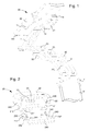
- the invention relates to a clasp for a bracelet, of the folding clasp type, comprising at least first and second blades, the first blade 1 being articulated to the second blade 2 by a first end, between a position closed, said bearing position, in which the first blade 1 is folded over the second blade 2, and an open position in which the first blade 1 is disengaged from the second blade 2.
- the first blade 1 carries at a second end a fastener 20 of a first strand 100 of a bracelet, a second strap strand 101 being connected at least indirectly to the second blade 2 by means of a fastening link 11 by for example, the first blade 1 having first locking means capable of holding the first blade 1 in its closed position.
- the strands 100, 101 may be made of materials such as leather, fabric, canvas, or any other material known to those skilled in the art for making bracelets or belts.
- the first locking means may be formed, for example, by at least one trigger 32 configured to maintain and / or release a pin, said lower pin 31, so as to maintain the first blade 1 in its closed position against the second blade 2 or release the first blade 1 in its unobstructed position.
- the second blade 2 may, for example, have a through hole at its center, said central orifice 25, the central orifice being configured to receive the lower pin 31 so that the lower pin 31 cooperates with the trigger.
- other locking means could have been envisaged by the skilled person in the context of the present invention.
- the base plate 21 and the cover 22 allows the first strand 100 to pass between the base plate 21 and the cover 22.
- the first strand 100 passes through the adjustment means, at the level of the articulation of the hood on the base plate.
- the first strand 100 is held in its position by means of holding means such as a pin, said upper nipple 30, intended to be inserted into a suitable hole of the first strand 100 for define an anchor point of the latter at the clasp.
- holding means such as a pin, said upper nipple 30, intended to be inserted into a suitable hole of the first strand 100 for define an anchor point of the latter at the clasp.
- other holding means could have been envisaged by those skilled in the art in the context of the present invention.
- the adjustment means also comprise second locking means for holding the cover 22 in the closed position on the base plate 21.
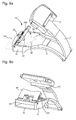
- the second locking means are formed by a pusher 24 arranged to be displaced in a longitudinal direction of the first strand 100, in response to an action by the user, between a first rest position in which the cover 22 is locked in the closed position on the base plate 21, and a second pushed position in which the cover 22 is disengaged from the base plate 21.
- the second locking means comprise return means, such as springs 230, configured to exert a force on the pusher 24 so as to maintain the pusher 24 in the closed position.
- the base plate 21 comprises guide means for the pusher 24 and the springs 230, the guide means being respectively in the form of a guide slot 210 on either side of the base plate 21 for the pusher 24 and a guide cylinder 211 for each spring 230, the springs 230 thus being held laterally in the guide cylinders 211.
- the guide slots 210 are provided open, so that the pusher 24 can cooperate with the side walls of the cover 21.
- the pusher 24 is formed by a body 240, of width equivalent to the width of the base plate 21, and has an arm 241 disposed at each of its ends, the arms 241 being configured to slide within the guide slots 210 and cooperating in support with the springs 230.
- each arm 241 of the pusher 24 comprises a pin 241 directed towards the outside of the guide slot 210 to cooperate with one of the side walls 220 of the hood 22.
- the pusher also has a through hole 243 at each arm 241, each of the through holes 243 being configured to pass a screw 212 attached to the base plate 21 and thereby hold the pusher 24 in place while being constrained by the springs 230.
- the holes Through-holes 243 are larger in diameter than those of the screws 212, the difference between the diameters of the hole 243 and the screw 212 defining the stroke length of the pusher 24.
- the cover 22 has an L-shaped groove 221 on the internal face of each of its side walls 220, preferably disposed near one of its ends, each L-shaped groove 221 being configured to cooperate with a pion 241 respective pusher 24.
- the cover 22 comprises on the inner face of each of its side walls 220 a pin, and each arm 241 of the pusher 24 comprises a groove configured to cooperate with a respective pin of the cover 22
- the grooves move and release the pins present on the side walls 220 of the cover 22.
- the springs 230 force the pusher 24 so that the body 240 of the pusher 24 protrudes slightly from the cover 22 and the pins 241 remain in place at the bottom of the grooves L 221.
- the user presses the pusher 24 so as to place the pegs 241 in abutment with the foot of the L of each L-shaped groove 221. The user can then raise the cover 22 and release the first strand 100 by lifting the latter in order to extract the upper nipple of the first strand 100.
- the user can use the same finger to press the pusher 24 and lift the cover 22, the finger arriving in the immediate vicinity of the cover 22 once the pusher in the pushed position.
- the clasp for a bracelet comprises first, second and third blades, the first blade 1 being articulated to the second blade 2 at one end, and the third blade 3 being hinged to the second blade 2 by the second end opposite the first end.
- the first blade 1 and the third blade 3 can pass from a closed position, called the wearing position, in which the first blade 1 and the third blade 3 are folded over the second blade 2, and an open position in which the first blade 1 and the third blade 3 are disengaged from the second blade 2.
- the first blade 1 carries at its second end a fastener 20 of a first strand 100 of a bracelet, a second strap strand 101 being connected at least indirectly to the second blade 2, the first blade 1 having first locking means 10 able to maintain the first blade 1 in its closed position.
- the fastener 20 comprises means for adjusting the length of the first strand 100 identical to those present in the first embodiment, therefore we do not go back to the description of these adjustment means.
- the second blade 2 comprises two longitudinal recesses 26 and 27 arranged symmetrically on either side of the central orifice 25.
- the longitudinal recesses 26 and 27 are respectively of complementary shape to the first blade 1 and the third blade 3 .
- first blade 1 and the third blade 3 rest at least partially in the longitudinal housing 26 and 27, so that the second end of the first blade 1 and the third blade 3 rests on the second blade 2 in the immediate vicinity of the central orifice 25.
- the base plate 21 has a recess 213 at the end receiving the pusher 24 so as to form a housing, between the base plate 21 and the pusher 24, which is configured to receive the second end of the third blade 3 when the first blade 1 and the third blade 3 are in the closed position.
- the fixing member 20 has a receptacle 200 in which the body 240 of the pusher 24 is housed when the first blade 1 and the third blade 3 are folded on the second blade 2 in closed position.
- the user folds at first the third blade 3 on the second blade 2 in the corresponding longitudinal recess 27, so that the second end of the third blade 3 is positioned above the orifice central 25. Then, the user folds the first blade 1 on the second blade 2 in the corresponding longitudinal recess 26, so that the second end of the first blade 1 is positioned above the central orifice 25 and that the second end of the third blade 3 rests at the hollow 213. Finally, the blades 1 and 3 are locked once the user positions the lower pin 31 in the central hole 25 so as to lock it through first locking means.
- the clasp comprises a first blade 1 articulated to a second blade 2 at a first end, between a closed position, called the wearing position, in which the first blade 1 is folded over the second blade 2, and an open position in which the first blade 1 is disengaged from the second blade 2.
- the second blade 2 carries at a second end a fastener 20 of a first strand 100 of a bracelet, a second strand of bracelet that can be connected at least indirectly to the first blade 1 by means of a rod 13 for example, the first blade 1 having first locking means adapted to maintain the first blade 1 in its closed position.
- the second blade comprises at its second end a bridge 40 for the passage of the first strand 100.
- the bridge 40 may be perforated according to the material used to manufacture the clasp blades, so as to reduce manufacturing costs.
- the first locking means may be formed, for example, by at least one trigger 32 configured to maintain and / or release a pin, said upper pin 30 'on the second blade 2, so as to maintain the first blade 1 in its position closed against the second blade 2 or release the first blade 1 in its disengaged position.
- the first blade 1 comprises a guide element 12 which makes it possible to guide the first blade 1 laterally relative to the second blade 2 when the first blade 1 is folded over the second blade 2.
- Another advantage of this Guiding element 12 is to prevent the first blade 1 to be moved laterally and thus prevent wear or even breakage of the upper pin 30 'when the clasp is closed.
- the fixing member 20 comprises means for adjusting the useful length of the bracelet, these adjustment means comprising a base plate 21 pivotally articulated at the second end of the second blade 2, the base plate being held by a bar 10
- the base plate 21 and the second blade 2 allows the first strand 100 to pass under the base plate 21 by the bridge 40 of the second blade 2.
- the first strand 100 passes through the means of adjustment, at the articulation of the base plate 21
- the first strand 100 is held in its position by means of holding means such as a nipple, said lower nipple 31 ', intended to be inserted into a suitable hole of the first strand 100 to define an anchor point of the latter to the clasp.
- holding means such as a nipple, said lower nipple 31 ', intended to be inserted into a suitable hole of the first strand 100 to define an anchor point of the latter to the clasp.
- other holding means could have been envisaged by those skilled in the art in the context of the present invention.
- the adjustment means also comprise second locking means for holding the base plate 21 in the closed position on the second blade 2.
- the second locking means are formed by a pusher 24 arranged to be moved in a longitudinal direction of the first strand 100, in response to an action by the user, between a first rest position in which the base plate 21 is locked in the closed position on the second blade 2, and a second pushed position in which the base plate 21 is disengaged from the second blade 2.
- the second locking means comprise return means, such as springs 230, configured to exert a force on the pusher 24 so as to maintain the pusher 24 in the closed position.
- the base plate 21 comprises guide means for the pusher 24 and the springs 230, the guide means being respectively in the form of a guide slot 210 on either side of the base plate 21 for the pusher 24 and a guide cylinder 211 for each spring 230, the springs 230 thus being held laterally in the guide cylinder 211.
- the pusher 24 is formed by a body 240, of width equivalent to the width of the base plate 21, and has an arm 241 disposed at each of its ends, the arms 241 being configured to slide within the guide slots 210 and cooperating in support with the springs 230.
- each arm 241 of the pusher 24 comprises an L-shaped groove 221 facing outwards to cooperate with one of the side walls 41, 42 of the bridge 40 of the second blade 2.
- the bridge 40 has a pin 242 on the inner face of each of its side walls 41, 42, preferably disposed near one of its ends, each pin 242 being configured to cooperate with a groove L 221 respective pusher 24.
- the skilled person can reverse the position of the pins 242 and grooves L 221.
- the pins 242 can be located on the pusher 24 and the grooves L 221 on the side walls 41 and 42 of the bridge 40 .
- the springs 230 force the pusher 24 so that the pins 241 of the bridge 40 remain in place at the bottom of the L-grooves 221 of the base plate 21.
- base 21 the user presses the pusher 24 so as to place the pins 241 in abutment at the foot of the L of each groove L 221. The user can then lift the base plate 21 and release the first strand 100 in lifting the latter so as to extract the nipple of the first strand 100.
- the invention also relates to a wristwatch comprising a bracelet provided with a clasp as described above.
- the second locking means comprise a pusher 24 arranged to be moved in a longitudinal direction of the strand, in response to an action by the user, between a first rest position in which the cover 22 is locked in position. closed on the base plate 21, and a second pushed position in which the cover 22 is disengaged from the base plate 21.
Landscapes
- Buckles (AREA)
Priority Applications (5)
| Application Number | Priority Date | Filing Date | Title |
|---|---|---|---|
| EP15164867.2A EP3085265B1 (de) | 2015-04-23 | 2015-04-23 | Verschluss für armband |
| US15/085,310 US10278460B2 (en) | 2015-04-23 | 2016-03-30 | Bracelet clasp |
| JP2016078761A JP6280589B2 (ja) | 2015-04-23 | 2016-04-11 | 締め輪クラスプ |
| KR1020160049493A KR101855068B1 (ko) | 2015-04-23 | 2016-04-22 | 팔찌 클래스프 |
| CN201610257154.8A CN106063620B (zh) | 2015-04-23 | 2016-04-22 | 链扣钩 |
Applications Claiming Priority (1)
| Application Number | Priority Date | Filing Date | Title |
|---|---|---|---|
| EP15164867.2A EP3085265B1 (de) | 2015-04-23 | 2015-04-23 | Verschluss für armband |
Publications (2)
| Publication Number | Publication Date |
|---|---|
| EP3085265A1 true EP3085265A1 (de) | 2016-10-26 |
| EP3085265B1 EP3085265B1 (de) | 2020-12-30 |
Family
ID=53002556
Family Applications (1)
| Application Number | Title | Priority Date | Filing Date |
|---|---|---|---|
| EP15164867.2A Active EP3085265B1 (de) | 2015-04-23 | 2015-04-23 | Verschluss für armband |
Country Status (5)
| Country | Link |
|---|---|
| US (1) | US10278460B2 (de) |
| EP (1) | EP3085265B1 (de) |
| JP (1) | JP6280589B2 (de) |
| KR (1) | KR101855068B1 (de) |
| CN (1) | CN106063620B (de) |
Cited By (1)
| Publication number | Priority date | Publication date | Assignee | Title |
|---|---|---|---|---|
| CN108991661A (zh) * | 2017-06-07 | 2018-12-14 | 奥米加股份有限公司 | 链扣钩 |
Families Citing this family (13)
| Publication number | Priority date | Publication date | Assignee | Title |
|---|---|---|---|---|
| US9949537B2 (en) * | 2015-03-06 | 2018-04-24 | Apple Inc. | Clasp mechanism for wrist-worn devices |
| CN107019297B (zh) * | 2016-01-29 | 2021-02-12 | 精工爱普生株式会社 | 表扣、表带及钟表 |
| EP3501325B1 (de) * | 2017-12-19 | 2020-07-22 | Omega SA | Verschluss für armband |
| USD877647S1 (en) * | 2018-01-16 | 2020-03-10 | Frank Boschman | Bracelet clasp for jewellery |
| CH715059A1 (de) * | 2018-05-31 | 2019-12-13 | Richemont Int Sa | Faltschliesse für Armbanduhr und Verfahren zum Nachrüsten einer solchen. |
| EP3666110B1 (de) * | 2018-12-13 | 2022-04-20 | Omega SA | Verstellbarer armbandverschluss |
| CH715815A1 (de) * | 2019-02-04 | 2020-08-14 | Bucherer Ag | Metallisches Uhrenarmband. |
| USD979442S1 (en) * | 2022-01-04 | 2023-02-28 | Lu Wang | Watch band |
| JP7683621B2 (ja) * | 2023-03-08 | 2025-05-27 | カシオ計算機株式会社 | 中留及びバンド |
| USD1110884S1 (en) * | 2023-03-10 | 2026-02-03 | Rolex Watch U.S.A., Inc. | Clasp |
| USD1018352S1 (en) * | 2023-09-05 | 2024-03-19 | Zhonghua Wu | Watch buckle |
| USD1012765S1 (en) * | 2023-09-05 | 2024-01-30 | Zhonghua Wu | Watch buckle |
| USD1103817S1 (en) * | 2024-06-03 | 2025-12-02 | Qi Wu | Watchband |
Citations (5)
| Publication number | Priority date | Publication date | Assignee | Title |
|---|---|---|---|---|
| DE61468C (de) * | J. schiffers in Düsseldorf | Leicht lösbare Schnalle | ||
| EP0344620A1 (de) * | 1988-05-31 | 1989-12-06 | G.T.F. S.r.l. | Verschluss für Uhrarmbänder, Armbänder, Schmuckartikel oder dergleichen |
| EP0607726A1 (de) | 1992-12-28 | 1994-07-27 | Maier S.A. | Faltverschluss für Armband mit verstellbarem Ende |
| EP1943917A2 (de) * | 2007-01-10 | 2008-07-16 | Boucledor SA | Klappbarer Verschluss für Armband |
| CH702523A2 (fr) * | 2010-01-08 | 2011-07-15 | Richemont Int Sa | Dispositif de réglage fin de la longueur utile d'un bracelet et fermoir correspondant. |
Family Cites Families (28)
| Publication number | Priority date | Publication date | Assignee | Title |
|---|---|---|---|---|
| US1741421A (en) * | 1929-01-16 | 1929-12-31 | Louis Stern Company | Foldable extension device |
| US3665564A (en) * | 1970-06-02 | 1972-05-30 | Bambi Kk | Three-fold metal fitting for adjusting steplessly the length of a watch band |
| US3797716A (en) * | 1970-10-24 | 1974-03-19 | Mochizuki Mfg Co Ltd | Watch band |
| IT8321828U1 (it) * | 1983-05-13 | 1984-11-13 | Lascor Spa | Fermaglio di chiusura estensibile in particolare per cinturino flessibile in cuoio o materiale plastico per orologio |
| JPH06327508A (ja) * | 1993-03-26 | 1994-11-29 | Citizen Watch Co Ltd | 時計バンドの中留構造 |
| GB2278148B (en) * | 1993-04-23 | 1996-08-21 | Ming Fung Metal Manufacturing | Wrist watch buckle |
| WO1996028064A1 (en) * | 1995-03-15 | 1996-09-19 | Citizen Watch Co., Ltd. | Device for fine adjustment of length of band-shaped accessory |
| AU7559396A (en) * | 1996-02-12 | 1997-09-02 | Gay Freres Vente Et Exportation S.A. | Strap clasp |
| EP1027842B1 (de) * | 1998-07-02 | 2010-04-28 | Citizen Holdings Co., Ltd. | Drehanschlag für faltverschlusselement eines bandförmigen schmuckes |
| WO2002074124A1 (en) * | 2001-03-19 | 2002-09-26 | Citizen Watch Co., Ltd. | Length adjustment device of band-shaped ornament |
| US6792652B2 (en) * | 2003-02-25 | 2004-09-21 | Luigi Ferrario | Unfolding clasp for bracelet |
| JP4545547B2 (ja) * | 2004-10-20 | 2010-09-15 | シチズンホールディングス株式会社 | 装身具の中留構造 |
| JP5149498B2 (ja) * | 2006-09-07 | 2013-02-20 | 株式会社バンビ | 装身具バンドの中留構造 |
| JP5354434B2 (ja) * | 2007-05-24 | 2013-11-27 | 株式会社バンビ | バンド用三折式中留構造およびそれを備えた腕時計 |
| CH702061A1 (fr) | 2009-10-26 | 2011-04-29 | Thi Technologies Horlogeres Ind S A | Fermoir extensible pour bracelet. |
| EP2534970B1 (de) * | 2011-06-16 | 2014-04-16 | Montres Breguet SA | Klappbarer Dreifachverschluss |
| EP2601855A1 (de) * | 2011-12-09 | 2013-06-12 | Omega SA | Verschluss eines Uhrenarmbands |
| EP2601856A1 (de) * | 2011-12-09 | 2013-06-12 | Omega SA | Verschluss eines Uhrenarmbands |
| EP2606762B1 (de) * | 2011-12-22 | 2015-08-12 | Montres Tudor S.A. | Armbandverschluss mit verschiedenen Längenregulierungen |
| EP2702891B1 (de) * | 2012-09-04 | 2015-11-18 | Omega SA | Verschluss eines Uhrenarmbands oder eines Kleidungsgürtels |
| JP6201482B2 (ja) * | 2012-09-20 | 2017-09-27 | カシオ計算機株式会社 | 駒体着脱用冶具 |
| EP2767184B1 (de) * | 2013-02-13 | 2015-04-08 | Omega SA | Verschluss für Uhrenarmband |
| EP2870893B1 (de) * | 2013-11-07 | 2016-06-08 | The Swatch Group Management Services AG | Armbandverschluss |
| EP2997847B1 (de) * | 2014-09-19 | 2018-04-18 | Omega SA | Verschluss für Armband oder Gürtel |
| KR102234724B1 (ko) * | 2014-09-23 | 2021-04-01 | 삼성전자 주식회사 | 웨어러블 디바이스의 버클장치 |
| EP3011857B1 (de) * | 2014-10-24 | 2017-03-15 | The Swatch Group Management Services AG | Armbandverschluss |
| US9681711B2 (en) * | 2015-05-28 | 2017-06-20 | Fossil Group, Inc. | Adjustable bracelet |
| CN107019297B (zh) * | 2016-01-29 | 2021-02-12 | 精工爱普生株式会社 | 表扣、表带及钟表 |
-
2015
- 2015-04-23 EP EP15164867.2A patent/EP3085265B1/de active Active
-
2016
- 2016-03-30 US US15/085,310 patent/US10278460B2/en active Active
- 2016-04-11 JP JP2016078761A patent/JP6280589B2/ja active Active
- 2016-04-22 KR KR1020160049493A patent/KR101855068B1/ko active Active
- 2016-04-22 CN CN201610257154.8A patent/CN106063620B/zh active Active
Patent Citations (5)
| Publication number | Priority date | Publication date | Assignee | Title |
|---|---|---|---|---|
| DE61468C (de) * | J. schiffers in Düsseldorf | Leicht lösbare Schnalle | ||
| EP0344620A1 (de) * | 1988-05-31 | 1989-12-06 | G.T.F. S.r.l. | Verschluss für Uhrarmbänder, Armbänder, Schmuckartikel oder dergleichen |
| EP0607726A1 (de) | 1992-12-28 | 1994-07-27 | Maier S.A. | Faltverschluss für Armband mit verstellbarem Ende |
| EP1943917A2 (de) * | 2007-01-10 | 2008-07-16 | Boucledor SA | Klappbarer Verschluss für Armband |
| CH702523A2 (fr) * | 2010-01-08 | 2011-07-15 | Richemont Int Sa | Dispositif de réglage fin de la longueur utile d'un bracelet et fermoir correspondant. |
Cited By (2)
| Publication number | Priority date | Publication date | Assignee | Title |
|---|---|---|---|---|
| CN108991661A (zh) * | 2017-06-07 | 2018-12-14 | 奥米加股份有限公司 | 链扣钩 |
| US10932532B2 (en) | 2017-06-07 | 2021-03-02 | Omega Sa | Bracelet clasp |
Also Published As
| Publication number | Publication date |
|---|---|
| CN106063620B (zh) | 2018-01-30 |
| JP6280589B2 (ja) | 2018-02-14 |
| EP3085265B1 (de) | 2020-12-30 |
| US10278460B2 (en) | 2019-05-07 |
| US20160309859A1 (en) | 2016-10-27 |
| KR101855068B1 (ko) | 2018-05-09 |
| JP2016202899A (ja) | 2016-12-08 |
| KR20160126913A (ko) | 2016-11-02 |
| CN106063620A (zh) | 2016-11-02 |
Similar Documents
| Publication | Publication Date | Title |
|---|---|---|
| EP3085265B1 (de) | Verschluss für armband | |
| EP2997847B1 (de) | Verschluss für Armband oder Gürtel | |
| EP3769640B1 (de) | Verschluss für uhrenarmband | |
| EP3412168B1 (de) | Verschluss für armband | |
| EP4059374B1 (de) | Armbandverschluss, der eine vorrichtung zur einstellung der länge des armbands umfasst, die eine rasche und bequeme anpassung ermöglicht | |
| EP2361523B1 (de) | Verschluss für Armband | |
| EP3501325B1 (de) | Verschluss für armband | |
| CH700230B1 (fr) | Fermoir de bracelet comprenant un dispositif de réglage fin de la longueur utile du bracelet. | |
| EP0661938B1 (de) | Faltverschluss für armbänder | |
| EP1836917B1 (de) | Längenverstellbares Armband | |
| EP0862097B1 (de) | Bandanschlusssteg zum Befestigen eines Armbandes und eine mit einem solchen Steg versehene Uhr | |
| EP4176757B1 (de) | Verschluss mit klappöse | |
| CH698981B1 (fr) | Dispositif de réglage de longueur pour bracelet, fermoire de bracelet et bracelet munis d'un tel dispositif. | |
| CH710133A2 (fr) | Fermoir pour bracelet ou ceinture. | |
| CH711022A2 (fr) | Fermoir pour bracelet. | |
| EP3417734B1 (de) | Armbandverschluss, der eine reguliervorrichtung der länge des armbands umfasst | |
| CH715632A2 (fr) | Fermoir de bracelet à boucle déployante comportant un dispositif de réglage de la longueur utile du bracelet. | |
| CH714461B1 (fr) | Fermoir pour bracelet avec mise à l'aise. | |
| FR2743641A1 (fr) | Montre-bracelet a cornes munie d'un dispositif de fixation d'un bracelet aux cornes et bracelet pour une telle montre | |
| CH713856A2 (fr) | Fermoir pour bracelet. | |
| FR3042389A1 (fr) | Systeme de verrouillage rapide d'une piece amovible et interchangeable par rapport a une piece fixe | |
| EP4005427B1 (de) | Verschluss für armband oder gürtel | |
| CH684151A5 (fr) | Fermoir de bracelet. | |
| CH712039B1 (fr) | Fermoir déployant pour bracelet. | |
| CH702308B1 (fr) | Objet portable ayant un bracelet interchangeable. |
Legal Events
| Date | Code | Title | Description |
|---|---|---|---|
| PUAI | Public reference made under article 153(3) epc to a published international application that has entered the european phase |
Free format text: ORIGINAL CODE: 0009012 |
|
| AK | Designated contracting states |
Kind code of ref document: A1 Designated state(s): AL AT BE BG CH CY CZ DE DK EE ES FI FR GB GR HR HU IE IS IT LI LT LU LV MC MK MT NL NO PL PT RO RS SE SI SK SM TR |
|
| AX | Request for extension of the european patent |
Extension state: BA ME |
|
| 17P | Request for examination filed |
Effective date: 20170426 |
|
| RBV | Designated contracting states (corrected) |
Designated state(s): AL AT BE BG CH CY CZ DE DK EE ES FI FR GB GR HR HU IE IS IT LI LT LU LV MC MK MT NL NO PL PT RO RS SE SI SK SM TR |
|
| STAA | Information on the status of an ep patent application or granted ep patent |
Free format text: STATUS: REQUEST FOR EXAMINATION WAS MADE |
|
| STAA | Information on the status of an ep patent application or granted ep patent |
Free format text: STATUS: EXAMINATION IS IN PROGRESS |
|
| 17Q | First examination report despatched |
Effective date: 20191121 |
|
| GRAP | Despatch of communication of intention to grant a patent |
Free format text: ORIGINAL CODE: EPIDOSNIGR1 |
|
| STAA | Information on the status of an ep patent application or granted ep patent |
Free format text: STATUS: GRANT OF PATENT IS INTENDED |
|
| INTG | Intention to grant announced |
Effective date: 20200910 |
|
| GRAS | Grant fee paid |
Free format text: ORIGINAL CODE: EPIDOSNIGR3 |
|
| GRAA | (expected) grant |
Free format text: ORIGINAL CODE: 0009210 |
|
| STAA | Information on the status of an ep patent application or granted ep patent |
Free format text: STATUS: THE PATENT HAS BEEN GRANTED |
|
| AK | Designated contracting states |
Kind code of ref document: B1 Designated state(s): AL AT BE BG CH CY CZ DE DK EE ES FI FR GB GR HR HU IE IS IT LI LT LU LV MC MK MT NL NO PL PT RO RS SE SI SK SM TR |
|
| REG | Reference to a national code |
Ref country code: GB Ref legal event code: FG4D Free format text: NOT ENGLISH |
|
| REG | Reference to a national code |
Ref country code: DE Ref legal event code: R096 Ref document number: 602015064035 Country of ref document: DE |
|
| REG | Reference to a national code |
Ref country code: AT Ref legal event code: REF Ref document number: 1349059 Country of ref document: AT Kind code of ref document: T Effective date: 20210115 |
|
| REG | Reference to a national code |
Ref country code: CH Ref legal event code: NV Representative=s name: ICB INGENIEURS CONSEILS EN BREVETS SA, CH |
|
| REG | Reference to a national code |
Ref country code: IE Ref legal event code: FG4D Free format text: LANGUAGE OF EP DOCUMENT: FRENCH |
|
| PG25 | Lapsed in a contracting state [announced via postgrant information from national office to epo] |
Ref country code: FI Free format text: LAPSE BECAUSE OF FAILURE TO SUBMIT A TRANSLATION OF THE DESCRIPTION OR TO PAY THE FEE WITHIN THE PRESCRIBED TIME-LIMIT Effective date: 20201230 Ref country code: RS Free format text: LAPSE BECAUSE OF FAILURE TO SUBMIT A TRANSLATION OF THE DESCRIPTION OR TO PAY THE FEE WITHIN THE PRESCRIBED TIME-LIMIT Effective date: 20201230 Ref country code: NO Free format text: LAPSE BECAUSE OF FAILURE TO SUBMIT A TRANSLATION OF THE DESCRIPTION OR TO PAY THE FEE WITHIN THE PRESCRIBED TIME-LIMIT Effective date: 20210330 Ref country code: GR Free format text: LAPSE BECAUSE OF FAILURE TO SUBMIT A TRANSLATION OF THE DESCRIPTION OR TO PAY THE FEE WITHIN THE PRESCRIBED TIME-LIMIT Effective date: 20210331 |
|
| REG | Reference to a national code |
Ref country code: AT Ref legal event code: MK05 Ref document number: 1349059 Country of ref document: AT Kind code of ref document: T Effective date: 20201230 |
|
| PG25 | Lapsed in a contracting state [announced via postgrant information from national office to epo] |
Ref country code: LV Free format text: LAPSE BECAUSE OF FAILURE TO SUBMIT A TRANSLATION OF THE DESCRIPTION OR TO PAY THE FEE WITHIN THE PRESCRIBED TIME-LIMIT Effective date: 20201230 Ref country code: SE Free format text: LAPSE BECAUSE OF FAILURE TO SUBMIT A TRANSLATION OF THE DESCRIPTION OR TO PAY THE FEE WITHIN THE PRESCRIBED TIME-LIMIT Effective date: 20201230 Ref country code: BG Free format text: LAPSE BECAUSE OF FAILURE TO SUBMIT A TRANSLATION OF THE DESCRIPTION OR TO PAY THE FEE WITHIN THE PRESCRIBED TIME-LIMIT Effective date: 20210330 |
|
| REG | Reference to a national code |
Ref country code: NL Ref legal event code: MP Effective date: 20201230 |
|
| PG25 | Lapsed in a contracting state [announced via postgrant information from national office to epo] |
Ref country code: HR Free format text: LAPSE BECAUSE OF FAILURE TO SUBMIT A TRANSLATION OF THE DESCRIPTION OR TO PAY THE FEE WITHIN THE PRESCRIBED TIME-LIMIT Effective date: 20201230 |
|
| REG | Reference to a national code |
Ref country code: LT Ref legal event code: MG9D |
|
| PG25 | Lapsed in a contracting state [announced via postgrant information from national office to epo] |
Ref country code: SK Free format text: LAPSE BECAUSE OF FAILURE TO SUBMIT A TRANSLATION OF THE DESCRIPTION OR TO PAY THE FEE WITHIN THE PRESCRIBED TIME-LIMIT Effective date: 20201230 Ref country code: PT Free format text: LAPSE BECAUSE OF FAILURE TO SUBMIT A TRANSLATION OF THE DESCRIPTION OR TO PAY THE FEE WITHIN THE PRESCRIBED TIME-LIMIT Effective date: 20210430 Ref country code: RO Free format text: LAPSE BECAUSE OF FAILURE TO SUBMIT A TRANSLATION OF THE DESCRIPTION OR TO PAY THE FEE WITHIN THE PRESCRIBED TIME-LIMIT Effective date: 20201230 Ref country code: LT Free format text: LAPSE BECAUSE OF FAILURE TO SUBMIT A TRANSLATION OF THE DESCRIPTION OR TO PAY THE FEE WITHIN THE PRESCRIBED TIME-LIMIT Effective date: 20201230 Ref country code: EE Free format text: LAPSE BECAUSE OF FAILURE TO SUBMIT A TRANSLATION OF THE DESCRIPTION OR TO PAY THE FEE WITHIN THE PRESCRIBED TIME-LIMIT Effective date: 20201230 Ref country code: CZ Free format text: LAPSE BECAUSE OF FAILURE TO SUBMIT A TRANSLATION OF THE DESCRIPTION OR TO PAY THE FEE WITHIN THE PRESCRIBED TIME-LIMIT Effective date: 20201230 Ref country code: NL Free format text: LAPSE BECAUSE OF FAILURE TO SUBMIT A TRANSLATION OF THE DESCRIPTION OR TO PAY THE FEE WITHIN THE PRESCRIBED TIME-LIMIT Effective date: 20201230 |
|
| PG25 | Lapsed in a contracting state [announced via postgrant information from national office to epo] |
Ref country code: PL Free format text: LAPSE BECAUSE OF FAILURE TO SUBMIT A TRANSLATION OF THE DESCRIPTION OR TO PAY THE FEE WITHIN THE PRESCRIBED TIME-LIMIT Effective date: 20201230 Ref country code: AT Free format text: LAPSE BECAUSE OF FAILURE TO SUBMIT A TRANSLATION OF THE DESCRIPTION OR TO PAY THE FEE WITHIN THE PRESCRIBED TIME-LIMIT Effective date: 20201230 |
|
| PG25 | Lapsed in a contracting state [announced via postgrant information from national office to epo] |
Ref country code: IS Free format text: LAPSE BECAUSE OF FAILURE TO SUBMIT A TRANSLATION OF THE DESCRIPTION OR TO PAY THE FEE WITHIN THE PRESCRIBED TIME-LIMIT Effective date: 20210430 |
|
| REG | Reference to a national code |
Ref country code: DE Ref legal event code: R097 Ref document number: 602015064035 Country of ref document: DE |
|
| PG25 | Lapsed in a contracting state [announced via postgrant information from national office to epo] |
Ref country code: IT Free format text: LAPSE BECAUSE OF FAILURE TO SUBMIT A TRANSLATION OF THE DESCRIPTION OR TO PAY THE FEE WITHIN THE PRESCRIBED TIME-LIMIT Effective date: 20201230 Ref country code: AL Free format text: LAPSE BECAUSE OF FAILURE TO SUBMIT A TRANSLATION OF THE DESCRIPTION OR TO PAY THE FEE WITHIN THE PRESCRIBED TIME-LIMIT Effective date: 20201230 |
|
| PLBE | No opposition filed within time limit |
Free format text: ORIGINAL CODE: 0009261 |
|
| STAA | Information on the status of an ep patent application or granted ep patent |
Free format text: STATUS: NO OPPOSITION FILED WITHIN TIME LIMIT |
|
| PG25 | Lapsed in a contracting state [announced via postgrant information from national office to epo] |
Ref country code: ES Free format text: LAPSE BECAUSE OF FAILURE TO SUBMIT A TRANSLATION OF THE DESCRIPTION OR TO PAY THE FEE WITHIN THE PRESCRIBED TIME-LIMIT Effective date: 20201230 Ref country code: DK Free format text: LAPSE BECAUSE OF FAILURE TO SUBMIT A TRANSLATION OF THE DESCRIPTION OR TO PAY THE FEE WITHIN THE PRESCRIBED TIME-LIMIT Effective date: 20201230 Ref country code: MC Free format text: LAPSE BECAUSE OF FAILURE TO SUBMIT A TRANSLATION OF THE DESCRIPTION OR TO PAY THE FEE WITHIN THE PRESCRIBED TIME-LIMIT Effective date: 20201230 |
|
| 26N | No opposition filed |
Effective date: 20211001 |
|
| PG25 | Lapsed in a contracting state [announced via postgrant information from national office to epo] |
Ref country code: LU Free format text: LAPSE BECAUSE OF NON-PAYMENT OF DUE FEES Effective date: 20210423 |
|
| REG | Reference to a national code |
Ref country code: BE Ref legal event code: MM Effective date: 20210430 |
|
| PG25 | Lapsed in a contracting state [announced via postgrant information from national office to epo] |
Ref country code: SI Free format text: LAPSE BECAUSE OF FAILURE TO SUBMIT A TRANSLATION OF THE DESCRIPTION OR TO PAY THE FEE WITHIN THE PRESCRIBED TIME-LIMIT Effective date: 20201230 |
|
| PG25 | Lapsed in a contracting state [announced via postgrant information from national office to epo] |
Ref country code: IE Free format text: LAPSE BECAUSE OF NON-PAYMENT OF DUE FEES Effective date: 20210423 |
|
| PG25 | Lapsed in a contracting state [announced via postgrant information from national office to epo] |
Ref country code: IS Free format text: LAPSE BECAUSE OF FAILURE TO SUBMIT A TRANSLATION OF THE DESCRIPTION OR TO PAY THE FEE WITHIN THE PRESCRIBED TIME-LIMIT Effective date: 20210430 |
|
| PG25 | Lapsed in a contracting state [announced via postgrant information from national office to epo] |
Ref country code: BE Free format text: LAPSE BECAUSE OF NON-PAYMENT OF DUE FEES Effective date: 20210430 |
|
| PG25 | Lapsed in a contracting state [announced via postgrant information from national office to epo] |
Ref country code: HU Free format text: LAPSE BECAUSE OF FAILURE TO SUBMIT A TRANSLATION OF THE DESCRIPTION OR TO PAY THE FEE WITHIN THE PRESCRIBED TIME-LIMIT; INVALID AB INITIO Effective date: 20150423 |
|
| PG25 | Lapsed in a contracting state [announced via postgrant information from national office to epo] |
Ref country code: CY Free format text: LAPSE BECAUSE OF FAILURE TO SUBMIT A TRANSLATION OF THE DESCRIPTION OR TO PAY THE FEE WITHIN THE PRESCRIBED TIME-LIMIT Effective date: 20201230 |
|
| PG25 | Lapsed in a contracting state [announced via postgrant information from national office to epo] |
Ref country code: SM Free format text: LAPSE BECAUSE OF FAILURE TO SUBMIT A TRANSLATION OF THE DESCRIPTION OR TO PAY THE FEE WITHIN THE PRESCRIBED TIME-LIMIT Effective date: 20201230 |
|
| P01 | Opt-out of the competence of the unified patent court (upc) registered |
Effective date: 20230701 |
|
| PG25 | Lapsed in a contracting state [announced via postgrant information from national office to epo] |
Ref country code: MK Free format text: LAPSE BECAUSE OF FAILURE TO SUBMIT A TRANSLATION OF THE DESCRIPTION OR TO PAY THE FEE WITHIN THE PRESCRIBED TIME-LIMIT Effective date: 20201230 |
|
| PG25 | Lapsed in a contracting state [announced via postgrant information from national office to epo] |
Ref country code: MT Free format text: LAPSE BECAUSE OF FAILURE TO SUBMIT A TRANSLATION OF THE DESCRIPTION OR TO PAY THE FEE WITHIN THE PRESCRIBED TIME-LIMIT Effective date: 20201230 |
|
| PGFP | Annual fee paid to national office [announced via postgrant information from national office to epo] |
Ref country code: DE Payment date: 20250319 Year of fee payment: 11 |
|
| PGFP | Annual fee paid to national office [announced via postgrant information from national office to epo] |
Ref country code: CH Payment date: 20250501 Year of fee payment: 11 |
|
| PG25 | Lapsed in a contracting state [announced via postgrant information from national office to epo] |
Ref country code: TR Free format text: LAPSE BECAUSE OF FAILURE TO SUBMIT A TRANSLATION OF THE DESCRIPTION OR TO PAY THE FEE WITHIN THE PRESCRIBED TIME-LIMIT Effective date: 20201230 |
|
| PGFP | Annual fee paid to national office [announced via postgrant information from national office to epo] |
Ref country code: GB Payment date: 20260319 Year of fee payment: 12 |
|
| PGFP | Annual fee paid to national office [announced via postgrant information from national office to epo] |
Ref country code: FR Payment date: 20260320 Year of fee payment: 12 |