EP3085295A1 - Dispositif d'endoscope - Google Patents
Dispositif d'endoscope Download PDFInfo
- Publication number
- EP3085295A1 EP3085295A1 EP14871544.4A EP14871544A EP3085295A1 EP 3085295 A1 EP3085295 A1 EP 3085295A1 EP 14871544 A EP14871544 A EP 14871544A EP 3085295 A1 EP3085295 A1 EP 3085295A1
- Authority
- EP
- European Patent Office
- Prior art keywords
- moving direction
- focusing lens
- images
- image
- lens
- Prior art date
- Legal status (The legal status is an assumption and is not a legal conclusion. Google has not performed a legal analysis and makes no representation as to the accuracy of the status listed.)
- Withdrawn
Links
- 230000003287 optical effect Effects 0.000 claims abstract description 35
- 238000005286 illumination Methods 0.000 description 9
- 238000000034 method Methods 0.000 description 9
- 238000003384 imaging method Methods 0.000 description 8
- 230000006870 function Effects 0.000 description 3
- 238000011156 evaluation Methods 0.000 description 2
- 238000003780 insertion Methods 0.000 description 2
- 230000037431 insertion Effects 0.000 description 2
- 238000003745 diagnosis Methods 0.000 description 1
- 238000010586 diagram Methods 0.000 description 1
- 230000000694 effects Effects 0.000 description 1
- 230000010349 pulsation Effects 0.000 description 1
Images


Classifications
-
- A—HUMAN NECESSITIES
- A61—MEDICAL OR VETERINARY SCIENCE; HYGIENE
- A61B—DIAGNOSIS; SURGERY; IDENTIFICATION
- A61B1/00—Instruments for performing medical examinations of the interior of cavities or tubes of the body by visual or photographical inspection, e.g. endoscopes; Illuminating arrangements therefor
- A61B1/00163—Optical arrangements
- A61B1/00188—Optical arrangements with focusing or zooming features
-
- A—HUMAN NECESSITIES
- A61—MEDICAL OR VETERINARY SCIENCE; HYGIENE
- A61B—DIAGNOSIS; SURGERY; IDENTIFICATION
- A61B1/00—Instruments for performing medical examinations of the interior of cavities or tubes of the body by visual or photographical inspection, e.g. endoscopes; Illuminating arrangements therefor
- A61B1/00064—Constructional details of the endoscope body
- A61B1/00071—Insertion part of the endoscope body
- A61B1/0008—Insertion part of the endoscope body characterised by distal tip features
- A61B1/00096—Optical elements
-
- A—HUMAN NECESSITIES
- A61—MEDICAL OR VETERINARY SCIENCE; HYGIENE
- A61B—DIAGNOSIS; SURGERY; IDENTIFICATION
- A61B1/00—Instruments for performing medical examinations of the interior of cavities or tubes of the body by visual or photographical inspection, e.g. endoscopes; Illuminating arrangements therefor
- A61B1/00131—Accessories for endoscopes
- A61B1/00133—Drive units for endoscopic tools inserted through or with the endoscope
-
- A—HUMAN NECESSITIES
- A61—MEDICAL OR VETERINARY SCIENCE; HYGIENE
- A61B—DIAGNOSIS; SURGERY; IDENTIFICATION
- A61B1/00—Instruments for performing medical examinations of the interior of cavities or tubes of the body by visual or photographical inspection, e.g. endoscopes; Illuminating arrangements therefor
- A61B1/04—Instruments for performing medical examinations of the interior of cavities or tubes of the body by visual or photographical inspection, e.g. endoscopes; Illuminating arrangements therefor combined with photographic or television appliances
- A61B1/045—Control thereof
-
- A—HUMAN NECESSITIES
- A61—MEDICAL OR VETERINARY SCIENCE; HYGIENE
- A61B—DIAGNOSIS; SURGERY; IDENTIFICATION
- A61B5/00—Measuring for diagnostic purposes; Identification of persons
- A61B5/06—Devices, other than using radiation, for detecting or locating foreign bodies ; Determining position of diagnostic devices within or on the body of the patient
-
- A—HUMAN NECESSITIES
- A61—MEDICAL OR VETERINARY SCIENCE; HYGIENE
- A61B—DIAGNOSIS; SURGERY; IDENTIFICATION
- A61B5/00—Measuring for diagnostic purposes; Identification of persons
- A61B5/06—Devices, other than using radiation, for detecting or locating foreign bodies ; Determining position of diagnostic devices within or on the body of the patient
- A61B5/065—Determining position of the probe employing exclusively positioning means located on or in the probe, e.g. using position sensors arranged on the probe
-
- G—PHYSICS
- G02—OPTICS
- G02B—OPTICAL ELEMENTS, SYSTEMS OR APPARATUS
- G02B23/00—Telescopes, e.g. binoculars; Periscopes; Instruments for viewing the inside of hollow bodies; Viewfinders; Optical aiming or sighting devices
- G02B23/24—Instruments or systems for viewing the inside of hollow bodies, e.g. fibrescopes
- G02B23/2407—Optical details
- G02B23/2423—Optical details of the distal end
- G02B23/243—Objectives for endoscopes
-
- G—PHYSICS
- G02—OPTICS
- G02B—OPTICAL ELEMENTS, SYSTEMS OR APPARATUS
- G02B23/00—Telescopes, e.g. binoculars; Periscopes; Instruments for viewing the inside of hollow bodies; Viewfinders; Optical aiming or sighting devices
- G02B23/24—Instruments or systems for viewing the inside of hollow bodies, e.g. fibrescopes
- G02B23/26—Instruments or systems for viewing the inside of hollow bodies, e.g. fibrescopes using light guides
-
- G—PHYSICS
- G02—OPTICS
- G02B—OPTICAL ELEMENTS, SYSTEMS OR APPARATUS
- G02B7/00—Mountings, adjusting means, or light-tight connections, for optical elements
- G02B7/28—Systems for automatic generation of focusing signals
- G02B7/36—Systems for automatic generation of focusing signals using image sharpness techniques, e.g. image processing techniques for generating autofocus signals
- G02B7/38—Systems for automatic generation of focusing signals using image sharpness techniques, e.g. image processing techniques for generating autofocus signals measured at different points on the optical axis, e.g. focussing on two or more planes and comparing image data
-
- H—ELECTRICITY
- H04—ELECTRIC COMMUNICATION TECHNIQUE
- H04N—PICTORIAL COMMUNICATION, e.g. TELEVISION
- H04N23/00—Cameras or camera modules comprising electronic image sensors; Control thereof
- H04N23/50—Constructional details
- H04N23/555—Constructional details for picking-up images in sites, inaccessible due to their dimensions or hazardous conditions, e.g. endoscopes or borescopes
-
- H—ELECTRICITY
- H04—ELECTRIC COMMUNICATION TECHNIQUE
- H04N—PICTORIAL COMMUNICATION, e.g. TELEVISION
- H04N23/00—Cameras or camera modules comprising electronic image sensors; Control thereof
- H04N23/60—Control of cameras or camera modules
- H04N23/67—Focus control based on electronic image sensor signals
- H04N23/673—Focus control based on electronic image sensor signals based on contrast or high frequency components of image signals, e.g. hill climbing method
-
- A—HUMAN NECESSITIES
- A61—MEDICAL OR VETERINARY SCIENCE; HYGIENE
- A61B—DIAGNOSIS; SURGERY; IDENTIFICATION
- A61B1/00—Instruments for performing medical examinations of the interior of cavities or tubes of the body by visual or photographical inspection, e.g. endoscopes; Illuminating arrangements therefor
- A61B1/00002—Operational features of endoscopes
- A61B1/00004—Operational features of endoscopes characterised by electronic signal processing
- A61B1/00006—Operational features of endoscopes characterised by electronic signal processing of control signals
-
- A—HUMAN NECESSITIES
- A61—MEDICAL OR VETERINARY SCIENCE; HYGIENE
- A61B—DIAGNOSIS; SURGERY; IDENTIFICATION
- A61B1/00—Instruments for performing medical examinations of the interior of cavities or tubes of the body by visual or photographical inspection, e.g. endoscopes; Illuminating arrangements therefor
- A61B1/04—Instruments for performing medical examinations of the interior of cavities or tubes of the body by visual or photographical inspection, e.g. endoscopes; Illuminating arrangements therefor combined with photographic or television appliances
-
- A—HUMAN NECESSITIES
- A61—MEDICAL OR VETERINARY SCIENCE; HYGIENE
- A61B—DIAGNOSIS; SURGERY; IDENTIFICATION
- A61B1/00—Instruments for performing medical examinations of the interior of cavities or tubes of the body by visual or photographical inspection, e.g. endoscopes; Illuminating arrangements therefor
- A61B1/04—Instruments for performing medical examinations of the interior of cavities or tubes of the body by visual or photographical inspection, e.g. endoscopes; Illuminating arrangements therefor combined with photographic or television appliances
- A61B1/05—Instruments for performing medical examinations of the interior of cavities or tubes of the body by visual or photographical inspection, e.g. endoscopes; Illuminating arrangements therefor combined with photographic or television appliances characterised by the image sensor, e.g. camera, being in the distal end portion
Definitions
- the present invention relates to an endoscope device, more particularly to an endoscope device having an auto focusing function.
- the conventional optical devices have adopted a low pixel number imaging element for reducing the size of the device, and can obtain images with sufficiently wide depth of field only by narrowing the aperture stop of the optical system.
- Patent Literature 1 discloses an Auto Focusing endoscope which drives the aperture stop and the lens, using brightness information.
- the auto focusing using the brightness information as described in Patent Literature 1 is insufficient in quality.
- information related to the brightness is information which correlates to the distance between the optical system and the object and which can be used for auto focusing, that cannot be sufficient information for high accuracy auto focusing when the object has pulsation or concave and convex portions.
- the endoscope apparatus since low invasiveness is required, it is desirable that the device is compact.
- the present invention has been made in view of these circumstances, and an object of the present invention is to improve the accuracy of the auto focusing in an endoscope device in which the observation depth can be changed and accurate observation images can be obtained.
- the present invention provides the following solutions.
- An aspect of the present invention is an endoscope device comprising the following elements: an optical system having a focusing lens; a lens moving unit which moves the focusing lens along an optical axis thereof in order to change an observation depth; an image capturing unit which obtains an optical image of an object from the optical system as a plurality of images each of which has a different focal position from each other; a moving direction determining section which determines whether to change the observation depth on the basis of the plurality of images, and determines, when the observation depth is determined to be changed, a moving direction toward which the focusing lens is to be moved on the bases of the images; and a drive control unit which controls the lens moving unit to move the focusing lens toward a determined moving direction.
- the observation is performed, appropriately changing the observation depth by moving the focusing lens of the optical system along the optical axis by means of the lens moving unit.
- the image capturing unit captures an optical image from the optical system as a plurality of images each of which has a different focal position from each other, and moving direction determining section determines whether or not to change the observation depth on the basis of these images.
- the moving direction determining section determines whether or not to change the observation depth prior to the focusing, it becomes possible to prevent unnecessary operations of moving the focusing lens 14a when the device is in the in-focus state, and also it becomes possible to stabilize the operation of the endoscope device.
- the moving direction of the focusing lens is determined by the moving direction determining section when the device determines that the switching of the observation depth is necessary, it is possible to prevent unnecessary operations of the focusing lens, and it is also possible to achieve accurate focusing even in the case in which the depth of field is narrow and therefore the focusing is difficult.
- the determinations as to whether to switch the observation depth and as to the moving direction of the focusing lens are performed based on a plurality of images each of which has a different focal position from each other.
- the characteristics of the plurality of images that is, the contrast, the brightness, the frequency component thereof, and the like can be utilized, and therefore, it is possible to perform an accurate focusing.
- the device further comprises a position detector for detecting position information which indicates a position of the focusing lens at the time of obtaining the plurality of images, wherein the moving direction determining section calculates contrasts of the plurality of images, respectively, and determines that the observation depth is to be changed when the calculated contrasts are smaller than a threshold value which is predetermined in relation to the position information.
- the device Since the characteristics of the images defer due to the position of the focusing lens, the device obtains the position information which indicates the position of the focusing lens at the time of obtaining the image. Also, the device calculates the contrast which indicates a characteristic of the image, and then determines whether or not to change the observation depth by comparing the contrast with the threshold value corresponding to the position information. Therefore, it is possible to accurately determine whether or not to change the observation depth.
- the moving direction determining section determines the moving direction of the focusing lens so that the observation depth is changed toward a direction by which the observation depth is moved from a focal position of an obtained image corresponding to a minimum contrast of the calculated contrasts to a focal position of an obtained image corresponding to a maximum contrast of the calculated contrasts.
- the image capturing unit captures a near point image whose focal position is at a near point and a distant point image whose focal position is at a distant point, and that the moving direction determining section calculates a contrast F1 of the near point image and a contrast F2 of the distant point image, and determines that the observation depth is to be changed when the following conditional expression (1) is satisfied.
- the near point threshold Th1 and the distant point threshold Th2 are predetermined so as to correspond to the position information of the focusing lens at the time of obtaining the near point image and the distant point image.
- the determination as to whether or not to change the observation depth can be done precisely, and therefore it becomes possible to improve the accuracy of the auto focusing.
- the moving direction determining section determines that the moving direction is a direction toward the near point when the following conditional expression (2) is satisfied, and that the moving direction is a direction toward the distant point when the following conditional expression (3) is satisfied.
- the determination as to whether or not to change the observation depth can be simplified, therefore it becomes possible to further improve the accuracy of the auto focusing.
- the present invention affords an advantage of improving the accuracy of the auto focusing in an endoscope device in which the observation depth can be changed and accurate observation images can be obtained.
- the endoscope device has a slender inserted portion 2 to be inserted into an object, and an endoscope controller 3 which performs various controls for supplying the illumination light to the insertion portion 2, obtaining observation images of the object, and the like, according to operational instructions by an operator.
- a light guide 11 for guiding the illumination light is inserted into the inserted portion 2.
- An illumination lens 12 which emits the illumination light toward the object is provided on the distal end side of the light guide 11, and the proximal end side of the light guide 11 is connected to the light source unit 25, which will be described later, via a cable and connector which are not shown in the drawings. Therefore, the illumination light from the light source unit 25 through the light guide 11 and the illumination lens 12 is irradiated to the object.
- an optical system 14 which forms an optical image of the illuminated object, is provided in the insertion portion 2.
- the optical system 14 has a focusing lens 14a, and can change the observation depth regarding the object by moving the focusing lens 14a in the optical axis direction.
- This embodiment is explained about a configuration in which the observation depth is changed to a magnified observation and a normal observation.
- the focusing lens 14a is moved in the optical axis direction by means of an actuator 15, and the focusing lens 14a is able to move within a predetermined range, and thereby the observation mode can be changed to the magnified and normal ones by moving the focusing lens 14a.
- the inserted portion 2 is provided with an image capturing unit 17 which obtains optical images of the object, which is formed by the optical system 14, and each of which has a plurality of images with different focal positions.
- image capturing unit 17 which obtains optical images of the object, which is formed by the optical system 14, and each of which has a plurality of images with different focal positions.
- the image capturing unit 17 comprises a polarizing beam splitter 19, mirror 20, and a ⁇ /4 wave plate 21, and thereby the image capturing unit 17 forms two optical images which are the distant point image and the near point image, using the condensed light by the optical system 14. Also, the image capturing unit 17 has an imaging element 18 whose imaging surfaces are located at the image forming positions, and obtains images at the two focal positions of the distant point image and the near point image.
- the image capturing unit 17 can perform a magnified observation, obtaining the near point image and the distant point image in the magnified observation mode. Also, when the focusing lens 14a is positioned on a distant point side of the movable range, it is possible to perform a normal observation, obtaining the near point image and the distant point image in the normal observation mode.
- the image capturing unit 17 is connected to an image signal processor 26 of the endoscope controller 3 via cable and a connector which are not shown in the drawings.
- the endoscope controller 3 includes the light source unit 25 which emits illumination light, the image processing unit 26 which performs a predetermined signal process on the image obtained by the imaging unit 17, and a drive control unit 27 that performs autofocusing by moving the focus lens by controlling the actuator, and a CPU 28 which controls these units.
- the light source unit 25 includes a lamp serving as the light source for generating illumination light, and a light amount adjusting unit which adjusts the amount of the light emitted from the lamp, and the light source unit 25 supplies a required amount of illuminating light to the light guide 11.
- the drive control unit 27 controls the actuator 15 to move the focus lens according to the command from the CPU 28. Also, the unit includes a position detector 30 for detecting the position information which indicates the current position of the actuator 15 in the movable range.
- the CPU 28 controls the above-described components, and determines whether or not to switch the observation depth based on an image obtained by the image capturing unit 17.
- the CPU 28 includes a moving direction determining section 31 which determines the moving direction of the focus lens on the basis of said images when it is determined that the switching of the observation depth becomes necessary, and outputs a determined moving direction to the drive control unit 27.
- the endoscope controller 3 includes a memory 29 which stores various types of data, such as a threshold value that is required when judging whether switching of the observation mode by the CPU 28 is necessary or not.
- the determination of necessity of the switching of the observation depth or the determination of the moving direction is performed based on the plurality of images obtained by the image capturing unit 17, preferably, for example, based on the characteristics of the images, the contrast, the brightness, the frequency component.
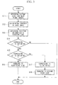
- the CPU 28 calculates the contrasts as an evaluation value for each of the images. That is, the contrasts are calculated so as to include the contrast of the near point image being F1 and as the contrast of the distant point image being F2, respectively.
- the CPU 28 obtains, from the position detector 30, position information indicating the position of the focusing lens 14a within the movable range at the time of obtaining the image in the step S11.
- threshold values Th1 and Th2 which correspond to the obtained position information of the focusing lens 14a are read out from the memory 29 as a first process.
- Th1 and Th2 are threshold values predetermined in accordance with the position of the focusing lens 14a when the distant point image and the near point image are obtained, and the threshold values are stored in the memory 29. Then, the CPU 28 determines whether the switching of the observation depth is necessary in order to satisfy the following conditional expression (1).
- step S14 when the above expression (1) is not satisfied, the movement of the focusing lens 14a is determined to be unnecessary, and the CPU 28 does not output any signal to the drive control unit 27.
- the process proceeds to the step S15, and the moving direction to which the focusing lens 14a is to be moved is determined for the switching of the observation depth.
- the moving direction of the focusing lens 14a is determined as follows. More specifically, when the following conditional expression (2) is satisfied, the process proceeds to the step S16 and determines that the moving direction of the focusing lens is the near point side. F 1 > F 2
- the moving direction determining section 31 outputs a signal to the drive control unit 27 so that the focusing lens 14 is moved toward the near point side.
- the signal for moving the lens to the magnified observation position is output from the CPU 28 to the drive control unit 27.
- the focusing lens 14a is positioned at the nearest point of the movable range, even if an additional signal for moving the lens toward the near point side is output, this does not cause any problem since the focusing lens 14a does not move beyond the movable range.
- the moving direction determining section 31 outputs a signal to the drive control unit 27 so that the focusing lens 14a is moved toward the distant point side. That is, when the focusing lens 14a is positioned in the magnified observation position, the CPU 28 outputs a signal, which is for moving the lens to the normal observation position, to the drive control unit 27.
- the focusing lens 14a When the focusing lens 14a is positioned at the most distant point of the movable range, even if an additional signal for moving the lens toward the distant point side is output, this does not cause any problem since the focusing lens 14a does not move beyond the movable range. On the other hand, it is possible not to output the signal for moving the lens toward the distant point side by detecting the current position of the focusing lens 14a.
- the optical images from the optical system 14 are respectively obtained as a plurality of images with different focal positions, and the determination as to whether or not to change the observation depth based on these images is performed. That is, since the device determines whether or not to switch the observation depth prior to the focusing, it becomes possible to prevent unnecessary operations of moving the focusing lens 14a when the device is in the in-focus state, and also it becomes possible to stabilize the operation of the endoscope device.
- the moving direction of the focusing lens 14a is determined when the device determines that the switching of the observation depth is necessary, it is possible to prevent unnecessary operations of the focusing lens 14a, and it is also possible to achieve accurate focusing even in the case in which the depth of field is narrow and therefore the focusing is difficult.
- the determinations as to whether to switch the observation depth and as to the moving direction of the focusing lens 14 are performed based on a plurality of images each of which has a different focal position from each other.
- the characteristics of the plurality of images that is, the contrast, the brightness, the frequency component thereof, and the like can be utilized, and therefore, it is possible to perform an accurate focusing.
Landscapes
- Life Sciences & Earth Sciences (AREA)
- Health & Medical Sciences (AREA)
- Physics & Mathematics (AREA)
- Engineering & Computer Science (AREA)
- Surgery (AREA)
- Optics & Photonics (AREA)
- Biophysics (AREA)
- Public Health (AREA)
- Animal Behavior & Ethology (AREA)
- Pathology (AREA)
- General Health & Medical Sciences (AREA)
- Veterinary Medicine (AREA)
- Biomedical Technology (AREA)
- Heart & Thoracic Surgery (AREA)
- Medical Informatics (AREA)
- Molecular Biology (AREA)
- Nuclear Medicine, Radiotherapy & Molecular Imaging (AREA)
- Radiology & Medical Imaging (AREA)
- General Physics & Mathematics (AREA)
- Astronomy & Astrophysics (AREA)
- Human Computer Interaction (AREA)
- Signal Processing (AREA)
- Multimedia (AREA)
- Computer Vision & Pattern Recognition (AREA)
- Endoscopes (AREA)
- Instruments For Viewing The Inside Of Hollow Bodies (AREA)
- Focusing (AREA)
- Camera Bodies And Camera Details Or Accessories (AREA)
- Automatic Focus Adjustment (AREA)
Applications Claiming Priority (2)
| Application Number | Priority Date | Filing Date | Title |
|---|---|---|---|
| JP2013259202 | 2013-12-16 | ||
| PCT/JP2014/083035 WO2015093412A1 (fr) | 2013-12-16 | 2014-12-12 | Dispositif d'endoscope |
Publications (2)
| Publication Number | Publication Date |
|---|---|
| EP3085295A1 true EP3085295A1 (fr) | 2016-10-26 |
| EP3085295A4 EP3085295A4 (fr) | 2017-10-04 |
Family
ID=53402758
Family Applications (1)
| Application Number | Title | Priority Date | Filing Date |
|---|---|---|---|
| EP14871544.4A Withdrawn EP3085295A4 (fr) | 2013-12-16 | 2014-12-12 | Dispositif d'endoscope |
Country Status (5)
| Country | Link |
|---|---|
| US (1) | US10070776B2 (fr) |
| EP (1) | EP3085295A4 (fr) |
| JP (1) | JP5881910B2 (fr) |
| CN (1) | CN105682531B (fr) |
| WO (1) | WO2015093412A1 (fr) |
Families Citing this family (5)
| Publication number | Priority date | Publication date | Assignee | Title |
|---|---|---|---|---|
| WO2018011857A1 (fr) * | 2016-07-11 | 2018-01-18 | オリンパス株式会社 | Dispositif d'endoscope |
| CN109744983B (zh) * | 2019-01-31 | 2024-05-10 | 北京超维景生物科技有限公司 | 变焦式腔体内窥镜探测装置及激光扫描腔体内窥镜 |
| CN111227771A (zh) * | 2020-01-09 | 2020-06-05 | 上海交通大学 | 工作距离可变的自聚焦oct内窥镜 |
| EP4184231B1 (fr) * | 2020-07-17 | 2025-11-12 | Sony Group Corporation | Système d'endoscope, processeur de commande d'endoscope et programme |
| CN113467071B (zh) * | 2021-07-27 | 2023-08-29 | 郑州光超医疗科技有限公司 | 一种可调焦的在体组织高分辨率光学扫描探头 |
Family Cites Families (25)
| Publication number | Priority date | Publication date | Assignee | Title |
|---|---|---|---|---|
| JPS5813075A (ja) * | 1981-07-16 | 1983-01-25 | Fuji Photo Film Co Ltd | ビデオカメラ用自動焦点調節装置 |
| US4873572A (en) * | 1987-02-27 | 1989-10-10 | Olympus Optical Co., Ltd. | Electronic endoscope apparatus |
| US4781448A (en) * | 1987-03-02 | 1988-11-01 | Medical Concepts Inc. | Zoom lens adapter for endoscopic camera |
| JPH0980323A (ja) * | 1995-09-11 | 1997-03-28 | Olympus Optical Co Ltd | 内視鏡装置 |
| JP4472130B2 (ja) | 2000-07-14 | 2010-06-02 | オリンパス株式会社 | 内視鏡装置 |
| US7469160B2 (en) * | 2003-04-18 | 2008-12-23 | Banks Perry S | Methods and apparatus for evaluating image focus |
| JP4336166B2 (ja) * | 2003-09-02 | 2009-09-30 | フジノン株式会社 | オートフォーカス機能を備えた電子内視鏡装置 |
| JP4377745B2 (ja) * | 2004-05-14 | 2009-12-02 | オリンパス株式会社 | 電子内視鏡 |
| JP4709579B2 (ja) * | 2005-04-26 | 2011-06-22 | オリンパスメディカルシステムズ株式会社 | カプセル型内視鏡 |
| US20070156021A1 (en) * | 2005-09-14 | 2007-07-05 | Bradford Morse | Remote imaging apparatus having an adaptive lens |
| US8233075B2 (en) * | 2007-05-24 | 2012-07-31 | Gyrus Acmi, Inc. | User-aided auto-focus |
| JP2009080413A (ja) | 2007-09-27 | 2009-04-16 | Fujinon Corp | 撮像光学系、内視鏡の撮像装置 |
| JP4987790B2 (ja) * | 2008-04-15 | 2012-07-25 | オリンパスメディカルシステムズ株式会社 | 撮像装置 |
| KR101594000B1 (ko) * | 2009-12-02 | 2016-02-26 | 삼성전자주식회사 | 포커스 렌즈의 이동 방향을 결정하는 오토포커싱 방법, 상기 방법을 기록한 기록 매체, 오토포커싱 장치 |
| JP5856733B2 (ja) | 2010-11-02 | 2016-02-10 | オリンパス株式会社 | 撮像装置 |
| JP5624955B2 (ja) * | 2011-07-21 | 2014-11-12 | オリンパスメディカルシステムズ株式会社 | 内視鏡装置 |
| US8672838B2 (en) * | 2011-08-12 | 2014-03-18 | Intuitive Surgical Operations, Inc. | Image capture unit in a surgical instrument |
| JP5948076B2 (ja) * | 2011-08-23 | 2016-07-06 | オリンパス株式会社 | フォーカス制御装置、内視鏡装置及びフォーカス制御方法 |
| JP5393926B2 (ja) * | 2011-08-24 | 2014-01-22 | オリンパスメディカルシステムズ株式会社 | 撮像装置及び撮像装置システム |
| JP5953187B2 (ja) * | 2011-10-11 | 2016-07-20 | オリンパス株式会社 | 合焦制御装置、内視鏡システム及び合焦制御方法 |
| JP5996218B2 (ja) * | 2012-03-07 | 2016-09-21 | オリンパス株式会社 | 内視鏡装置及び内視鏡装置の作動方法 |
| JP6120491B2 (ja) * | 2012-05-01 | 2017-04-26 | オリンパス株式会社 | 内視鏡装置及び内視鏡装置のフォーカス制御方法 |
| JP6013020B2 (ja) * | 2012-05-02 | 2016-10-25 | オリンパス株式会社 | 内視鏡装置及び内視鏡装置の作動方法 |
| JP6176978B2 (ja) * | 2013-01-31 | 2017-08-09 | オリンパス株式会社 | 内視鏡用画像処理装置、内視鏡装置、内視鏡用画像処理装置の作動方法及び画像処理プログラム |
| JP5695808B1 (ja) | 2013-04-19 | 2015-04-08 | オリンパスメディカルシステムズ株式会社 | 内視鏡装置 |
-
2014
- 2014-12-12 JP JP2015534859A patent/JP5881910B2/ja active Active
- 2014-12-12 CN CN201480059152.7A patent/CN105682531B/zh active Active
- 2014-12-12 EP EP14871544.4A patent/EP3085295A4/fr not_active Withdrawn
- 2014-12-12 WO PCT/JP2014/083035 patent/WO2015093412A1/fr not_active Ceased
-
2016
- 2016-04-25 US US15/137,576 patent/US10070776B2/en active Active
Also Published As
| Publication number | Publication date |
|---|---|
| US10070776B2 (en) | 2018-09-11 |
| CN105682531B (zh) | 2018-01-26 |
| US20160235281A1 (en) | 2016-08-18 |
| WO2015093412A1 (fr) | 2015-06-25 |
| CN105682531A (zh) | 2016-06-15 |
| EP3085295A4 (fr) | 2017-10-04 |
| JP5881910B2 (ja) | 2016-03-09 |
| JPWO2015093412A1 (ja) | 2017-03-16 |
Similar Documents
| Publication | Publication Date | Title |
|---|---|---|
| US10070776B2 (en) | Endoscope device with lens moving unit for changing observation depth based on captured images | |
| EP2689708B1 (fr) | Dispositif endoscopique et procédé de mesure | |
| US10682040B2 (en) | Endoscope apparatus and focus control method for endoscope apparatus | |
| US9345391B2 (en) | Control device, endoscope apparatus, aperture control method, and information storage medium | |
| KR101106852B1 (ko) | 광학식 3차원 계측 장치 및 필터 처리 방법 | |
| EP2950127A1 (fr) | Dispositif d'imagerie et procédé de commande de dispositif d'imagerie | |
| US10827906B2 (en) | Endoscopic surgery image processing apparatus, image processing method, and program | |
| US9621814B2 (en) | Image pickup for endoscope and method for operating image pickup system for endoscope | |
| JP6533284B2 (ja) | フォーカス制御装置、撮像装置、内視鏡システム、フォーカス制御装置の制御方法 | |
| US9241628B2 (en) | Ophthalmologic apparatus, method for controlling ophthalmologic apparatus, and program | |
| EP2749923A1 (fr) | Dispositif de commande de mise au point, dispositif endoscopique et procédé de commande de mise au point | |
| EP2728392A1 (fr) | Système microscope | |
| US11921277B2 (en) | Image acquisition device and image acquisition method | |
| JP6312410B2 (ja) | アライメント装置、顕微鏡システム、アライメント方法、及びアライメントプログラム | |
| US12607839B2 (en) | Microscope system and microscope control device | |
| JP5022580B2 (ja) | 内視鏡装置 | |
| US20140132918A1 (en) | Ophthalmologic apparatus and method | |
| US20120050678A1 (en) | Photographing apparatus, and control method and program for the same | |
| EP1972982A1 (fr) | Microscope avec mecanisme de mise au point automatique et procede de reglage de celui-ci | |
| JP5145698B2 (ja) | 顕微鏡用焦点検出装置と、これを具備する顕微鏡 | |
| US20140160429A1 (en) | Ophthalmic imaging apparatus, control method of ophthalmic imaging apparatus and storage medium | |
| JP2010022772A (ja) | 内視鏡及び生体観察システム | |
| JP2015210396A (ja) | アライメント装置、顕微鏡システム、アライメント方法、及びアライメントプログラム | |
| WO2024014079A1 (fr) | Dispositif d'observation de cellule et procédé d'imagerie utilisé dans un dispositif d'observation de cellule | |
| JP4804383B2 (ja) | 自動焦点調節装置および撮像装置 |
Legal Events
| Date | Code | Title | Description |
|---|---|---|---|
| PUAI | Public reference made under article 153(3) epc to a published international application that has entered the european phase |
Free format text: ORIGINAL CODE: 0009012 |
|
| 17P | Request for examination filed |
Effective date: 20160712 |
|
| AK | Designated contracting states |
Kind code of ref document: A1 Designated state(s): AL AT BE BG CH CY CZ DE DK EE ES FI FR GB GR HR HU IE IS IT LI LT LU LV MC MK MT NL NO PL PT RO RS SE SI SK SM TR |
|
| AX | Request for extension of the european patent |
Extension state: BA ME |
|
| DAX | Request for extension of the european patent (deleted) | ||
| A4 | Supplementary search report drawn up and despatched |
Effective date: 20170904 |
|
| RIC1 | Information provided on ipc code assigned before grant |
Ipc: A61B 1/04 20060101ALI20170829BHEP Ipc: G02B 23/24 20060101ALI20170829BHEP Ipc: G02B 23/26 20060101ALI20170829BHEP Ipc: A61B 1/00 20060101AFI20170829BHEP Ipc: G02B 7/28 20060101ALI20170829BHEP Ipc: H04N 5/232 20060101ALI20170829BHEP |
|
| STAA | Information on the status of an ep patent application or granted ep patent |
Free format text: STATUS: EXAMINATION IS IN PROGRESS |
|
| 17Q | First examination report despatched |
Effective date: 20180713 |
|
| STAA | Information on the status of an ep patent application or granted ep patent |
Free format text: STATUS: THE APPLICATION IS DEEMED TO BE WITHDRAWN |
|
| 18D | Application deemed to be withdrawn |
Effective date: 20181124 |