EP3085328A1 - Support de traitement orthodontique - Google Patents
Support de traitement orthodontique Download PDFInfo
- Publication number
- EP3085328A1 EP3085328A1 EP16150015.2A EP16150015A EP3085328A1 EP 3085328 A1 EP3085328 A1 EP 3085328A1 EP 16150015 A EP16150015 A EP 16150015A EP 3085328 A1 EP3085328 A1 EP 3085328A1
- Authority
- EP
- European Patent Office
- Prior art keywords
- groove
- bracket
- base
- sidewall
- lateral sidewall
- Prior art date
- Legal status (The legal status is an assumption and is not a legal conclusion. Google has not performed a legal analysis and makes no representation as to the accuracy of the status listed.)
- Withdrawn
Links
- 239000004606 Fillers/Extenders Substances 0.000 claims abstract description 21
- 230000000694 effects Effects 0.000 abstract description 10
- 238000004904 shortening Methods 0.000 abstract description 2
- 238000010586 diagram Methods 0.000 description 14
- 238000000034 method Methods 0.000 description 6
- 229910001000 nickel titanium Inorganic materials 0.000 description 5
- 210000002455 dental arch Anatomy 0.000 description 4
- 210000004283 incisor Anatomy 0.000 description 4
- 206010061274 Malocclusion Diseases 0.000 description 3
- 230000001815 facial effect Effects 0.000 description 3
- 239000010935 stainless steel Substances 0.000 description 3
- 229910001220 stainless steel Inorganic materials 0.000 description 3
- 229910001040 Beta-titanium Inorganic materials 0.000 description 2
- RTAQQCXQSZGOHL-UHFFFAOYSA-N Titanium Chemical compound [Ti] RTAQQCXQSZGOHL-UHFFFAOYSA-N 0.000 description 2
- 239000000919 ceramic Substances 0.000 description 2
- 230000002349 favourable effect Effects 0.000 description 2
- 229910001069 Ti alloy Inorganic materials 0.000 description 1
- 230000002159 abnormal effect Effects 0.000 description 1
- 210000001909 alveolar process Anatomy 0.000 description 1
- 239000013078 crystal Substances 0.000 description 1
- 230000007812 deficiency Effects 0.000 description 1
- 208000037265 diseases, disorders, signs and symptoms Diseases 0.000 description 1
- 230000003993 interaction Effects 0.000 description 1
- 239000000463 material Substances 0.000 description 1
- 239000004033 plastic Substances 0.000 description 1
- 229920003023 plastic Polymers 0.000 description 1
Images


Classifications
-
- A—HUMAN NECESSITIES
- A61—MEDICAL OR VETERINARY SCIENCE; HYGIENE
- A61C—DENTISTRY; APPARATUS OR METHODS FOR ORAL OR DENTAL HYGIENE
- A61C7/00—Orthodontics, i.e. obtaining or maintaining the desired position of teeth, e.g. by straightening, evening, regulating, separating, or by correcting malocclusions
- A61C7/12—Brackets; Arch wires; Combinations thereof; Accessories therefor
- A61C7/14—Brackets; Fixing brackets to teeth
- A61C7/141—Brackets with reinforcing structure, e.g. inserts
-
- A—HUMAN NECESSITIES
- A61—MEDICAL OR VETERINARY SCIENCE; HYGIENE
- A61C—DENTISTRY; APPARATUS OR METHODS FOR ORAL OR DENTAL HYGIENE
- A61C7/00—Orthodontics, i.e. obtaining or maintaining the desired position of teeth, e.g. by straightening, evening, regulating, separating, or by correcting malocclusions
- A61C7/12—Brackets; Arch wires; Combinations thereof; Accessories therefor
- A61C7/14—Brackets; Fixing brackets to teeth
- A61C7/143—Brackets with two or more recesses for arch wires
-
- A—HUMAN NECESSITIES
- A61—MEDICAL OR VETERINARY SCIENCE; HYGIENE
- A61C—DENTISTRY; APPARATUS OR METHODS FOR ORAL OR DENTAL HYGIENE
- A61C7/00—Orthodontics, i.e. obtaining or maintaining the desired position of teeth, e.g. by straightening, evening, regulating, separating, or by correcting malocclusions
- A61C7/12—Brackets; Arch wires; Combinations thereof; Accessories therefor
- A61C7/14—Brackets; Fixing brackets to teeth
- A61C7/16—Brackets; Fixing brackets to teeth specially adapted to be cemented to teeth
Definitions
- the present invention belongs to the field of medical device, specifically relating to an orthodontic treatment bracket.
- Malocclusion is a misalignment or incorrect relation between the teeth of two dental arches, and the occlusion disorder and skeletal disharmony of the face is caused thereby. Therefore, two major tasks of orthodontic treatment are: first is position adjustment, namely adjusting the position of teeth so as to correct the malpositioned teeth; second is orientation adjustment, namely adjusting the three-dimensional orientation of teeth, so as to regain normal three-dimensional orientation for abnormally orientated teeth.
- the purporse of treatment is to achieve normal standard of occlusion, meanwhile improving profile.
- the position adjustment aims to create large clearance and small friction
- the orientation adjustment is intended to reach small clearance and large friction.
- orthodontic bracket is crucial for the success of position adjustment and orientation adjustment.
- orthodontic brackets available in domestic and foreign markets can be divided according its structure:
- the contact area between the correction archwire and the orthodontic bracket groove is small, namely the so-called “point contact”.
- the "point contact” can reduce friction, making it easier to move the teeth during the position adjustment, but the "point contact” also means that the correction archwire cannot fully fit with the bracket during the orientation adjustment or effectively adjust the three-dimensional orientation of teeth, thus the treatment effect is limited.
- the contact area between the archwire and the bracket groove is large, namely multiple point contacts. This leads to a big friction between the archwire and the bracket, thus making the teeth harder to move and the treatment duration longer in the position adjustment procedure.
- the present invention is related to a great bracket which can meet the different requirements of position adjustment and orientation adjustment, so as to accurately control the three directions of teeth, improve tooth occlusion, coordinate facial proportion, and at the same time shorten the treatment process.
- the size and shape of the left and right subgrooves of the preferred groove extender 3 are the same, forming a groove that extends to the left and the right with groove 2.
- a lateral auxiliary groove 4 which is parallel with groove 2 inside the groove base
- the preferred auxiliary groove is arc-shaped, consisting of an upper lateral sidewall 41 and a lower lateral sidewall 42 and a top wall 44, wherein the inner surfaces of the said upper lateral sidewall 41 and lower lateral sidewall 42 are wavy folding and relatively protruded, the number of the wavy folding and protruded surfaces on the inner side of each sidewall is 2-8, equally spaced and / or symmetrical, and each folding surface 43 intersects two by two, forming intersecting lines that are parallel with the upper lateral sidewall 41 and the lower lateral sidewall 42.
- a vertical tube slot 5 that passes through the groove base 21 and auxiliary groove 4 can be provided along the longitudinal center line of the bracket base 1, and the diameter of the preferred vertical tube slot 5 is 0.018-0.020 inches.
- the length of the preferred groove is 0.074-0.145 inches, and the whole groove , after inserting the fitting piece of the groove, shall be 0.019-0.039 inches longer.
- the length of the preferred auxiliary groove is 0.137-0.157 inches, the width is 0.018-0.020 inches, and the depth is 0.018-0.020 inches.
- the preferred groove and the auxiliary groove have an axial tilt ⁇ , of which the numerical value is adjusted on the basis of the axial tilt value of the dental crown; when the bracket is used for mandibular incisor, the ⁇ value is the axial tilt value of the dental crown plus 2°; when the bracket is used for other teeth, the ⁇ value is the axial tilt value of the dental crown plus 4°, so as to compensate the "Angle escape"caused by the gap between the archwire and the groove.
- the base plane of preferred groove and the surface of the bracket base form a torque angle ⁇ , of which the numerical value is adjusted on the basis of the torque angle value of the dental crown; when the bracket is used for the upper teeth, the value of the torque angle ⁇ is the torque angle value of the dental crown plus 3-14°; when the bracket is used for the lower teeth, the value of torque angle ⁇ is the torque angle value of the dental crown plus 1-5°.
- the preferred groove is square, the width is 0.018-0.022 inches, and the depth is 0.022-0.025 inches.
- the purpose of using the double-groove bracket clinically is to rely on the two archwires placed in the two grooves to form mechanical match, so as to control the three-dimensional position of the teeth.
- the distance between the two grooves of the current double-groove bracket is very close, and both are located at the middle position of the whole bracket, so when used clinically, the two grooves are close to the corresponding position of the center of clinical crown, therefore its correction effect is not signicantly different from single-groove bracket (the groove is usually located at the middle position of the whole bracket, corresponding to the position of the center of clinical crown).
- the center of clinical crown is far from the center of resistance of tooth movement at the tooth root (the center of resistance of tooth is basically the same with the geometric center of the tooth root, and the center of resistance of unirooted teeth is located at the proximal alveolar ridge of the dental long axis, about 1/2 to 1/3 of the root length), when securing the bracket to this position, be it the groove of single-groove bracket or double-groove bracket, it is relatively far from the center of resistance of tooth movement, making it hard to effectively control three directions and reach the treatment requirements for tooth occlusion and facial shape improvement during orientation adjustment.
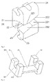
- the present invention provides an orthodontic treatment bracket with double grooves, including a bracket base 1.
- a bracket base 1 There is a mesial groove 2 and a distal auxiliary groove 4' on the outer surface of the bracket base, which are parallel, wherein the said mesial groove 2 and the distal auxiliary groove 4' are located on the upper and lower sides of the bracket base 1 respectively, and the distance between the mesidal groove 2 and the bracket base is greater than the distance between the distal auxiliary groove 4' and bracket base, and the vertical interval between the lateral center line a1 of the mesidal groove and the lateral center line a2 of the distal auxiliary groove is 0.086-0.196 inches.
- the said mesial groove 2 consists of a groove base 21 secured on the bracket base and the upper and lower sidewalls 22 & 23.
- the said upper sidewall 22 and lower sidewall 23 extend outward to form an upper bracket wing 24 and a lower bracket wing 25.
- the upper sidewall 22 of the said groove consists of an upper lateral sidewall 221 and an upper sloped sidewall 222 which is formed by bend upward at one end thereof, with an obtuse angle between them.
- the lower sidewall 23 of the said groove consists of the lower lateral sidewall 231 and the lower sloped sidewall 232 which is formed by bend downward at one end thereof, with an obtuse angle between them.
- the upper lateral sidewall 221 and the lower lateral sidewall 231 are parallel, and the upper sloped sidewall 222 and the lower sloped sidewall 232 are parallel.
- the said groove 2 also has a detachable groove extender 3, which includes a connecting section 31 and the left & right subgrooves 32 & 33.
- the connecting section 31 connects the left & right subgrooves 32 & 33, each of which 32 consists of a subgroove base 321 and an upper lateral sidewall 322 and a lower lateral sidewall 323 located on the subgroove base.
- each subgroove is in the same plane with the upper lateral sidewall 22 and the lower lateral sidewall 23 of groove 2 respectively, and the said subgroove base 321 are in the same plane with the groove base 21, forming the mesial groove that extends to the left and right.
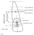
- distal and distal are defined by the distance between the groove and the center of resistance of tooth movement.
- the groove close to the center of resistance of tooth movement is the mesial groove, and the one far from the center of resistance of tooth movement is the distal auxiliary groove (as shown in FIG.11 ).
- the center of clinical crown is the midpoint of the facial axis of clinical crown, which is the marking point frequently used by the straight archwire bracket.
- the bracket When using the said new bracket of the present invention, the bracket is placed on the surface of the dental crown so that the mesial groove is located at the tooth root of the crown center and the distal auxiliary groove is located at the occlusion part of the crown center, and the distance between the lateral center line a1 of the mesidal groove and the center of clinical crown A is made greater than the distance between the lateral center line a2 of the distal auxiliary groove and the center of clinical crown A.
- the thin, soft and flexible NiTi round wire is placed into the distal auxiliary groove, and because it is relatively far from the center of resistance of tooth movement, it can promote the fast movement of the teeth and improve the efficiency of position adjustment.
- the thick, hard and flexible NiTi or stainless steel rectangular archwire is placed into the mesial groove, and because it is relatively close to the center of resistance of tooth movement, it can promote precise control of the three-dimensional movement of teeth.
- the aforementioned distal auxiliary groove can directly use the surface of the bracket base as the groove base, and the distance between the base of the mesial groove and the bracket base is greater than 0; or, the base of the mesial groove and the base of the distal auxiliary groove are higher than the surface of the bracket base, the distance between the base of the mesial groove and the bracket base is greater than the distance between the base of distal auxiliary groove and the bracket base; the mesial groove during use can fully apply the torque effect of the bracket and improve the accuracy of orientation adjustment; the vertical interval between the lateral center line of the mesidal groove and that of the distal auxiliary groove is 0.086-0.196 inches, so as to meet the different requirements for main and auxiliary grooves in different clinical stages of position adjustment and orientation adjustment.
- Arc-shaped bracket base that can better fit with the tooth surface is preferred for the aforementioned orthodontic treatment bracket with double groove; further, lines can be added to the side of the bracket base that fits with teeth so as to increase the friction with the teeth and fit better.
- a vertical tube slot 5 that passes through the bracket base 21 of the mesial groove and the distal auxiliary groove 4' can be located along the longitudinal center line of the bracket base (the said vertical tube slot 5 passes through the bracket base 21, not intersects with the archwire slot of the mesial groove, but intersects with the archwire slot of the distal auxiliary groove).
- the diameter of the preferred vertical tube slot 5 is 0.018-0.020 inches, so as to insert relevant accessories during the clinical orthodontic treatment.
- the distal auxiliary groove 4' is secured on the bracket base 1, consisting of the upper lateral sidewall 41' and the lower lateral sidewall 42' and the outer surface of the bracket base.
- the inner surfaces of the upper lateral sidewall 41' and the lower lateral sidewall 42' are wavy folding and relatively protruded.
- the number of the wavy folding and protruded surfaces on the inner side of each sidewall is 2-8, equally spaced and / or symmetrical, and each folding surface 43' intersects two by two, forming the intersecting lines that are parallel with the upper lateral sidewall 41' and the lower lateral sidewall 42'.
- the upper and lower sidewalls of the archwire and groove form paired point contact.
- the upper and lower lateral sidewall 41' and 42' of the preferred distal auxiliary groove extend, arch and intersect to form the top wall 44' of the groove, forming a tubular groove with an arc-shaped inner top wall and an opening to the buccal and labial side.
- the paired upper and lower folding surfaces on the inner surface of the upper lateral sidewall 41' and lower lateral sidewall 42' extend upward, arch and intersect with the inner top wall of the groove to form a smooth cambered surface.
- the length of the archwire slot of the preferred mesial groove is 0.074-0.145 inches; after inserting the fitting piece of the groove, the whole archwire slot is 0.019-0.039 inches longer.
- the length of the archwire slot of the preferred distal auxiliary groove is 0.137-0.157 inches, the width is 0.018-0.020 inches, and the depth is 0.018-0.020 inches.
- the preferred mesial groove and distal auxiliary groove have an axial tilt ⁇ , of which the numerical value is adjusted on the basis of the axial tilt value of the dental crown; when the bracket is used for mandibular incisor, the ⁇ value is the axial tilt value of the tooth plus 2°; when the bracket is used for other teeth, the ⁇ value is the axial tilt value of the tooth plus 4°, so as to compensate the "Angle escape"caused by the gap between the archwire and the groove.
- the base plane of preferred mesidal groove and the surface of the bracket base form a torque angle ⁇ , of which the numerical value is adjusted on the basis of the torque angle value of the dental crown; when the bracket is used for the upper teeth, the value of the torque angle ⁇ is the torque angle value of the dental crown of the upper teeth plus 3-14°; when the bracket is used for the lower teeth, the value of torque angle ⁇ is the torque angle value of the dental crown of the lower teeth plus 1-5°.
- the preferred mesial groove is square, with the width of 0.018-0.022 inches and the depth of 0.022-0.025 inches; the vertical distance between the lateral center line of the said mesial groove and the lateral center line of the center of clinical crown is 0.065-0.147 inches, and the vertical distance between the lateral center line of the distal auxiliary groove and the lateral center line of the center of clinical crown is 0.021-0.049 inches.
- All the aforementioned brackets can be made up of any suitable material, such as biological ceramics, crystal ceramics, titanium alloy, plastics and so on.
- the fitting surface between the curved bracket body and the teeth has anti-sliding lines.
- An orthodontic treatment bracket as shown in FIG.1-3 , comprising a bracket base 1 and a groove 2, which consists of a groove base 21 secured on the bracket base 1, an upper sidewall 22 and a lower sidewall 23, wherein the said upper sidewall 22 and lower sidewall 23 extend outward to form an upper bracket wing 24 and a lower bracket wing 25 respectively, and the said upper sidewall 22 of said groove consists of an upper lateral sidewall 221 and an upper sloped sidewall 222 which is formed by bend upward at one end thereof, and the said lower sidewall 23 consists of a lower lateral sidewall 231 and a lower sloped sidewall 232 which is formed by bend downward at one end thereof (or, described as the upper sidewall 22 of said mesial groove 2 consists of the upper lateral sidewall 221 and the upper sloped sidewall 222 which is formed by bend upper left at left end thereof, and the lower sidewall 23 of said mesial groove consists of the lower lateral sidewall 231 and the lower sloped sidewall 232 which is formed by bend but
- the upper lateral sidewall 221 and the lower lateral sidewall 231 are parallel, and the upper sloped sidewall 222 and the lower sloped sidewall 232 are parallel.
- the said groove also has a detachable groove extender 3, which includes a connecting section 31 and two subgrooves, left and right 32.
- the connecting section 31 connects the left & right subgrooves 32, each of which 32 consists of a subgroove base 321 and an upper lateral sidewall 322 and a lower lateral sidewall 323 located thereon.
- the groove size and shape of each subgroove 32 are the same with groove 2.
- the aforementioned groove with a groove extender can be used separately or in combination according to the position adjustment or orientation adjustment stage of orthodontics, specifically:
- auxiliary groove 4 is arc-shaped, comprising the upper lateral sidewall 41 and lower lateral sidewall 42 and the top wall 44, wherein the inner surfaces of two lateral sidewalls are wavy folding and relatively protruded, the number of protuberances of the wavy folding and protruded surfaces is 2-8, equally spaced and / or symmetrical, and each folding surface 43' intersects two by two, forming intersecting lines that are parallel with the upper lateral sidewall 41 and the lower lateral sidewall 42.
- This embodiment chooses the suitable size on the basis of Embodiments 1 and 2.
- the diameter of the vertical tube slot 4 is 0.018-0.020 inches
- the length of the groove 2 is 0.074-0.145 inches
- the whole groove, after inserting a groove extender 3 is 0.019-0.039 inches longer.
- the length of the auxiliary groove 4 is 0.137-0.157 inches. See the schematic diagram 9 of the torque angle ⁇ of the mesial groove set forth in Embodiment 5 and the schematic diagram 10 of the axial tilt ⁇ , the angle of inclination ⁇ and the included angle ⁇ of the bracket.
- the groove 2 and the auxiliary groove 4 have an axial tilt ⁇ , the numerical value of which is adjusted on the basis of the axial tilt value of dental crown; when the bracket is used for mandibular incisor, the ⁇ value is the axial tilt value of the tooth plus 2°; when the bracket is used for other teeth, the ⁇ value is the axial tilt value of the tooth plus 4°, so as to compensate the "Angle escape"caused by the gap between the archwire and the groove.
- the base plane of the groove and the surface of the bracket base form a torque angle ⁇ , the numerical value of which is adjusted on the basis of the torque angle value of the dental crown; when the bracket is used for the upper teeth, the value of the torque angle ⁇ is the torque angle value of the dental crown plus 3-14°; when the bracket is used for the lower teeth, the value of torque angle ⁇ is the torque angle value of the dental crown plus 1-5°.
- the groove is square, with the width of 0.018-0.022 inches and the depth of 0.022-0.025 inches.
- An orthodontic treatment bracket with double grooves as shown in Fig.4-10 , comprising the bracket base 1, There is a mesial groove 2 and a distal auxiliary groove 4' on the outer surface of the bracket base, which are parallel, wherein the said mesial groove 2 and the distal auxiliary groove 4' are located on the upper and lower sides of the bracket base 1, respectively, and the distance between the base of the mesidal groove 2 and the bracket base is greater than the distance between the base of the distal auxiliary groove 4' and bracket base, and the vertical interval d between the lateral center line of the mesidal groove and the lateral center line of the distal auxiliary groove is 0.086-0.196 inches.
- the said mesial groove 2 is of square shape, comprising the groove base 21 secured on the bracket base 1 and the upper and lower sidewalls 22 & 23.
- the said upper sidewall 22 and lower sidewall 23 extend outward to form an upper bracket wing 24 and a lower bracket wing 25.
- the upper sidewall 22 of the said groove consists of an upper lateral sidewall 221 and an upper sloped sidewall 222 which is formed by bend upper-right at right end thereof
- the lower sidewall 23 consists of a lower lateral sidewall 231 and a lower sloped sidewall 232 which is formed by bend lower left at left end thereof (or, described as the upper sidewall 22 of said mesial groove 2 consists of the upper lateral sidewall 221 and the upper sloped sidewall 222 which is formed by bend upper left at left end thereof
- the lower sidewall 23 of said mesial groove consists of the lower lateral sidewall 231 and the lower sloped sidewall 232 which is formed by bend buttom-right at right end thereof).
- the upper & lower lateral sidewalls are located at the two sides of the longitudinal center line, the upper & lower lateral sidewalls 221 & 231 are parallel, and the upper & lower sloped sidewalls 222 & 232 are parallel.
- the said groove also has a detachable groove extender 3, which includes a connecting section 31 and two subgrooves, left and right 32 & 33.
- the said connecting section 31 connects the left & right subgrooves 32 & 33, each 32 or 33 consisting of a subgroove base 321 and an upper lateral sidewall 322 and a lower lateral sidewall 323 located at the subgroove base.
- the bracket base 1 is arc-shaped.
- the distal auxiliary groove 4' is secured on the bracket base 1, as shown in FIG.8 , consisting of two parallel upper and lower lateral sidewalls 41 & 42 and the outer surface of the bracket base.
- Each folding surface is rectangular, which intersects two by two to form fold lines vertical to the groove base.
- This embodiment chooses the suitable size on the basis of Embodiment 4.
- the diameter of the vertical tube slot 5 is 0.018-0.020 inches; the mesial groove is square, with length of 0.074-0.145 inches, width of 0.018-0.022 inches and depth of 0.022-0.025 inches; the length of the distal auxiliary groove is 0.137-0.157 inches, the width is 0.018-0.020 inches, and the depth is 0.018-0.020 inches.
- the mesial groove 2 and the distal auxiliary groove 4' have an axial tilt ⁇ , the numerical value of which is adjusted on the basis of the axial tilt value of the dental crown; when the bracket is used for mandibular incisor, the ⁇ value is the axial tilt value of the tooth plus 2°; when the bracket is used for other teeth, the ⁇ value is the axial tilt value of the tooth plus 4°, so as to compensate the "Angle escape"caused by the gap between the archwire and the groove.
- the base plane of the mesial groove and the surface of the bracket base form a torque angle ⁇ , the numerical value of which is adjusted on the basis of the torque angle value of the dental crown; when the bracket is used for the upper teeth, the value of the torque angle ⁇ is the torque angle value of the dental crown of the upper teeth plus 3-14°; when the bracket is used for the lower teeth, the value of torque angle ⁇ is the torque angle value of the dental crown of the lower teeth plus 1-5°.
- the bracket When using the said new bracket, the bracket is placed on the surface of the dental crown, the mesial groove is close to the center of resistance of tooth movement, the distal auxiliary groove is far from the center of resistance of tooth movement, the mesial groove is located at the tooth root of the mesial groove, and the distal auxiliary groove is located at the occlusion side.
- the vertical distance between the lateral center line of the mesidal groove and the lateral center line of the center of clinical crown is 0.065-0.147 inches
- the vertical distance between the lateral center line of the distal auxiliary groove and the lateral center line of the center of clinical crown is 0.021-0.049 inches.
- the distal auxiliary groove is relatively far from the center of resistance of tooth movement, so the orthodontic force can quickly realize teeth tipping movement through filamentary light force, which can accelerate the position adjustment.
- the mesial groove is close to the center of resistance of tooth movement, thus the elastic force applied by the correction archwire is also close to the center of resistance, realizing the stable movement of all the teeth, this mode of force application can effectively control the movement of teeth in three directions, improve the effect of the orientation adjustment and shorten the duration thereof.
Landscapes
- Health & Medical Sciences (AREA)
- Oral & Maxillofacial Surgery (AREA)
- Dentistry (AREA)
- Epidemiology (AREA)
- Life Sciences & Earth Sciences (AREA)
- Animal Behavior & Ethology (AREA)
- General Health & Medical Sciences (AREA)
- Public Health (AREA)
- Veterinary Medicine (AREA)
- Dental Tools And Instruments Or Auxiliary Dental Instruments (AREA)
Applications Claiming Priority (1)
| Application Number | Priority Date | Filing Date | Title |
|---|---|---|---|
| CN201510197038.7A CN104970889B (zh) | 2015-04-23 | 2015-04-23 | 一种牙科正畸治疗托槽 |
Publications (1)
| Publication Number | Publication Date |
|---|---|
| EP3085328A1 true EP3085328A1 (fr) | 2016-10-26 |
Family
ID=54268218
Family Applications (1)
| Application Number | Title | Priority Date | Filing Date |
|---|---|---|---|
| EP16150015.2A Withdrawn EP3085328A1 (fr) | 2015-04-23 | 2016-01-04 | Support de traitement orthodontique |
Country Status (3)
| Country | Link |
|---|---|
| US (1) | US20160310238A1 (fr) |
| EP (1) | EP3085328A1 (fr) |
| CN (1) | CN104970889B (fr) |
Families Citing this family (2)
| Publication number | Priority date | Publication date | Assignee | Title |
|---|---|---|---|---|
| CN114601579B (zh) * | 2022-04-06 | 2025-07-22 | 华中科技大学同济医学院附属协和医院 | 一种用于控根的多维度正畸牵引装置 |
| CN115444590B (zh) * | 2022-09-13 | 2024-08-09 | 天津正丽科技有限公司 | 一种矫治系统 |
Citations (5)
| Publication number | Priority date | Publication date | Assignee | Title |
|---|---|---|---|---|
| US5125832A (en) * | 1986-06-26 | 1992-06-30 | Tp Orthodontics, Inc. | Bracket for permitting tipping and limiting uprighting |
| WO2003082138A1 (fr) * | 2002-03-25 | 2003-10-09 | Tp Orthodontics, Inc. | Bracket orthodontique |
| US20060204917A1 (en) * | 2005-03-14 | 2006-09-14 | Charles Clor | Orthodontic correction device |
| WO2013055529A1 (fr) * | 2011-10-10 | 2013-04-18 | 3M Innovative Properties Company | Appareils orthodontiques ayant des fentes d'arc dentaire conique |
| CN203898470U (zh) * | 2014-03-28 | 2014-10-29 | 陈启锋 | 一种带辅助管舌侧托槽 |
Family Cites Families (15)
| Publication number | Priority date | Publication date | Assignee | Title |
|---|---|---|---|---|
| US4107844A (en) * | 1976-11-15 | 1978-08-22 | Kurz Craven H | Orthodontic appliance |
| JPS5982013U (ja) * | 1982-11-25 | 1984-06-02 | 藤田 欣也 | 歯科矯正装置 |
| US4669980A (en) * | 1984-11-05 | 1987-06-02 | Degnan Edward V | Orthodontic appliance |
| US4674978A (en) * | 1986-06-04 | 1987-06-23 | Raul Acevedo | Orthodontic appliance |
| US20110287378A1 (en) * | 2002-10-29 | 2011-11-24 | Rmo, Inc. | Orthodontic appliance with encoded information formed in the base |
| US7192274B2 (en) * | 2003-12-08 | 2007-03-20 | 3M Innovative Properties Company | Ceramic orthodontic appliance with archwire slot liner |
| US7153130B2 (en) * | 2004-06-10 | 2006-12-26 | 3M Innovative Properties Company | Orthodontic appliance with removable insert |
| CN2922832Y (zh) * | 2006-06-26 | 2007-07-18 | 陈启锋 | 喇叭口活动翼托槽 |
| US7845941B2 (en) * | 2007-11-02 | 2010-12-07 | Mark Minium | Orthodontic instrument for use with adjustable orthodontic apparatus |
| WO2010119880A1 (fr) * | 2009-04-16 | 2010-10-21 | 株式会社ジーシー | Appareil orthodontique |
| BRPI1100503B1 (pt) * | 2011-02-15 | 2022-04-26 | Temistocles Uriarte Zucchi | Braquete interativo/passivo |
| TR201101724A2 (tr) * | 2011-02-22 | 2012-07-23 | M�Derr�S Ertan | Modüler ortodontik braket sistemi. |
| US8550814B1 (en) * | 2012-08-16 | 2013-10-08 | Monte Collins | Multi-component orthodontic bracket assembly |
| US9717660B2 (en) * | 2014-02-28 | 2017-08-01 | Regents Of The University Of Minnesota | Fluoride releasing dental composition and dental appliance |
| CN204655153U (zh) * | 2015-04-23 | 2015-09-23 | 赵喜林 | 一种牙科正畸治疗托槽 |
-
2015
- 2015-04-23 CN CN201510197038.7A patent/CN104970889B/zh not_active Expired - Fee Related
-
2016
- 2016-01-04 EP EP16150015.2A patent/EP3085328A1/fr not_active Withdrawn
- 2016-01-15 US US14/996,276 patent/US20160310238A1/en not_active Abandoned
Patent Citations (5)
| Publication number | Priority date | Publication date | Assignee | Title |
|---|---|---|---|---|
| US5125832A (en) * | 1986-06-26 | 1992-06-30 | Tp Orthodontics, Inc. | Bracket for permitting tipping and limiting uprighting |
| WO2003082138A1 (fr) * | 2002-03-25 | 2003-10-09 | Tp Orthodontics, Inc. | Bracket orthodontique |
| US20060204917A1 (en) * | 2005-03-14 | 2006-09-14 | Charles Clor | Orthodontic correction device |
| WO2013055529A1 (fr) * | 2011-10-10 | 2013-04-18 | 3M Innovative Properties Company | Appareils orthodontiques ayant des fentes d'arc dentaire conique |
| CN203898470U (zh) * | 2014-03-28 | 2014-10-29 | 陈启锋 | 一种带辅助管舌侧托槽 |
Also Published As
| Publication number | Publication date |
|---|---|
| US20160310238A1 (en) | 2016-10-27 |
| CN104970889B (zh) | 2017-07-28 |
| CN104970889A (zh) | 2015-10-14 |
Similar Documents
| Publication | Publication Date | Title |
|---|---|---|
| US12521208B2 (en) | Orthodontic appliance with non-sliding, tied archwire | |
| US4859179A (en) | Edgewise bracket with Sved shaped slot and control means | |
| US4664626A (en) | System for automatically preventing overtipping and/or overuprighting in the begg technique | |
| JP3124911B2 (ja) | 低輪郭歯科矯正装置およびその製造方法 | |
| JP2020520737A (ja) | 様々なサイズのアーチワイヤスロットを有する歯列矯正システム | |
| CN211583589U (zh) | 调整上下颌位关系的牙科器械及牙齿矫治系统 | |
| EP2724685A1 (fr) | Appareil orthodontique personnalisé ayant une fonction orthoaxiale | |
| JP4662582B2 (ja) | 歯科矯正用ブラケット | |
| JP2009535174A (ja) | 調整されたブラケットプロファイルを有する歯列矯正器具 | |
| US20200330189A1 (en) | Lingual orthodontic appliance | |
| US20250064558A1 (en) | An archwire | |
| JP2007522852A (ja) | 舌側ブラケット | |
| CN205411356U (zh) | 正畸牵引埋伏阻生牙用牵引弹簧 | |
| US11083547B2 (en) | Self-ligating bracket system with passive or interactive clip | |
| EP3085327A2 (fr) | Nouveau support orthodontique | |
| EP3085328A1 (fr) | Support de traitement orthodontique | |
| US6139317A (en) | Orthodontic appliance | |
| EP3745993A1 (fr) | Appareil orthodontique à autoligature en céramique ayant une force de traction labiale élevée | |
| CN115120365A (zh) | 牙科矫治辅助装置、壳状牙科矫治器及牙科器械 | |
| CN111727020B (zh) | 用于治疗咬合不正的正畸托架设备和方法 | |
| TWM630136U (zh) | 牙齒矯治輔助裝置、殼狀牙齒矯治器及牙科器械 | |
| CN115252180A (zh) | 力导控三系统口腔正畸矫治器 | |
| CN111214300A (zh) | 一种窄槽沟宽翼的牙齿正畸主动自锁托槽 | |
| WO2007087697A2 (fr) | Bracket orthodontique à prescription variable | |
| CN216754655U (zh) | 一种用于压低前牙的矫治装置 |
Legal Events
| Date | Code | Title | Description |
|---|---|---|---|
| PUAI | Public reference made under article 153(3) epc to a published international application that has entered the european phase |
Free format text: ORIGINAL CODE: 0009012 |
|
| 17P | Request for examination filed |
Effective date: 20160104 |
|
| AK | Designated contracting states |
Kind code of ref document: A1 Designated state(s): AL AT BE BG CH CY CZ DE DK EE ES FI FR GB GR HR HU IE IS IT LI LT LU LV MC MK MT NL NO PL PT RO RS SE SI SK SM TR |
|
| AX | Request for extension of the european patent |
Extension state: BA ME |
|
| STAA | Information on the status of an ep patent application or granted ep patent |
Free format text: STATUS: THE APPLICATION IS DEEMED TO BE WITHDRAWN |
|
| 18D | Application deemed to be withdrawn |
Effective date: 20180801 |