EP3085480A1 - Foret en alliage dur à tête remplaçable autobloquante - Google Patents
Foret en alliage dur à tête remplaçable autobloquante Download PDFInfo
- Publication number
- EP3085480A1 EP3085480A1 EP16165921.4A EP16165921A EP3085480A1 EP 3085480 A1 EP3085480 A1 EP 3085480A1 EP 16165921 A EP16165921 A EP 16165921A EP 3085480 A1 EP3085480 A1 EP 3085480A1
- Authority
- EP
- European Patent Office
- Prior art keywords
- cutter head
- cutter
- protrusions
- self
- drill bit
- Prior art date
- Legal status (The legal status is an assumption and is not a legal conclusion. Google has not performed a legal analysis and makes no representation as to the accuracy of the status listed.)
- Withdrawn
Links
- 239000000956 alloy Substances 0.000 title claims abstract description 38
- 229910045601 alloy Inorganic materials 0.000 title claims abstract description 37
- 238000005553 drilling Methods 0.000 claims abstract description 53
- 238000000034 method Methods 0.000 claims abstract description 11
- 230000008569 process Effects 0.000 claims abstract description 8
- 230000005540 biological transmission Effects 0.000 abstract description 2
- 230000006870 function Effects 0.000 description 9
- 238000005520 cutting process Methods 0.000 description 8
- 238000003754 machining Methods 0.000 description 8
- 230000000694 effects Effects 0.000 description 2
- 238000004519 manufacturing process Methods 0.000 description 2
- 238000010297 mechanical methods and process Methods 0.000 description 2
- 230000005226 mechanical processes and functions Effects 0.000 description 2
- 230000007704 transition Effects 0.000 description 2
- 229910000831 Steel Inorganic materials 0.000 description 1
- 238000013459 approach Methods 0.000 description 1
- 230000006872 improvement Effects 0.000 description 1
- 230000014759 maintenance of location Effects 0.000 description 1
- 230000009467 reduction Effects 0.000 description 1
- 239000007787 solid Substances 0.000 description 1
- 239000010959 steel Substances 0.000 description 1
- 239000002023 wood Substances 0.000 description 1
Images


Classifications
-
- B—PERFORMING OPERATIONS; TRANSPORTING
- B23—MACHINE TOOLS; METAL-WORKING NOT OTHERWISE PROVIDED FOR
- B23B—TURNING; BORING
- B23B51/00—Tools for drilling machines
-
- B—PERFORMING OPERATIONS; TRANSPORTING
- B23—MACHINE TOOLS; METAL-WORKING NOT OTHERWISE PROVIDED FOR
- B23B—TURNING; BORING
- B23B51/00—Tools for drilling machines
- B23B51/02—Twist drills
-
- B—PERFORMING OPERATIONS; TRANSPORTING
- B23—MACHINE TOOLS; METAL-WORKING NOT OTHERWISE PROVIDED FOR
- B23B—TURNING; BORING
- B23B2205/00—Fixation of cutting inserts in holders
- B23B2205/02—Fixation using an elastically deformable clamping member
-
- B—PERFORMING OPERATIONS; TRANSPORTING
- B23—MACHINE TOOLS; METAL-WORKING NOT OTHERWISE PROVIDED FOR
- B23B—TURNING; BORING
- B23B2222/00—Materials of tools or workpieces composed of metals, alloys or metal matrices
- B23B2222/28—Details of hard metal, i.e. cemented carbide
-
- B—PERFORMING OPERATIONS; TRANSPORTING
- B23—MACHINE TOOLS; METAL-WORKING NOT OTHERWISE PROVIDED FOR
- B23B—TURNING; BORING
- B23B2222/00—Materials of tools or workpieces composed of metals, alloys or metal matrices
- B23B2222/84—Steel
-
- B—PERFORMING OPERATIONS; TRANSPORTING
- B23—MACHINE TOOLS; METAL-WORKING NOT OTHERWISE PROVIDED FOR
- B23B—TURNING; BORING
- B23B2251/00—Details of tools for drilling machines
- B23B2251/02—Connections between shanks and removable cutting heads
-
- B—PERFORMING OPERATIONS; TRANSPORTING
- B23—MACHINE TOOLS; METAL-WORKING NOT OTHERWISE PROVIDED FOR
- B23B—TURNING; BORING
- B23B2251/00—Details of tools for drilling machines
- B23B2251/04—Angles, e.g. cutting angles
-
- B—PERFORMING OPERATIONS; TRANSPORTING
- B23—MACHINE TOOLS; METAL-WORKING NOT OTHERWISE PROVIDED FOR
- B23B—TURNING; BORING
- B23B2251/00—Details of tools for drilling machines
- B23B2251/04—Angles, e.g. cutting angles
- B23B2251/043—Helix angles
-
- B—PERFORMING OPERATIONS; TRANSPORTING
- B23—MACHINE TOOLS; METAL-WORKING NOT OTHERWISE PROVIDED FOR
- B23B—TURNING; BORING
- B23B2251/00—Details of tools for drilling machines
- B23B2251/14—Configuration of the cutting part, i.e. the main cutting edges
-
- B—PERFORMING OPERATIONS; TRANSPORTING
- B23—MACHINE TOOLS; METAL-WORKING NOT OTHERWISE PROVIDED FOR
- B23B—TURNING; BORING
- B23B2251/00—Details of tools for drilling machines
- B23B2251/18—Configuration of the drill point
-
- Y—GENERAL TAGGING OF NEW TECHNOLOGICAL DEVELOPMENTS; GENERAL TAGGING OF CROSS-SECTIONAL TECHNOLOGIES SPANNING OVER SEVERAL SECTIONS OF THE IPC; TECHNICAL SUBJECTS COVERED BY FORMER USPC CROSS-REFERENCE ART COLLECTIONS [XRACs] AND DIGESTS
- Y10—TECHNICAL SUBJECTS COVERED BY FORMER USPC
- Y10T—TECHNICAL SUBJECTS COVERED BY FORMER US CLASSIFICATION
- Y10T408/00—Cutting by use of rotating axially moving tool
- Y10T408/89—Tool or Tool with support
- Y10T408/909—Having peripherally spaced cutting edges
- Y10T408/9098—Having peripherally spaced cutting edges with means to retain Tool to support
- Y10T408/90987—Wedge means
Definitions
- the present invention relates to a hard alloy drill bit, in particular to a self-locking head-replaceable hard alloy drill bit which has the self-locking function and is convenient for cutter head replacement.
- Stony drill bits are used by Shuiren Shi for drilling wood to make fire, which is regards as the origin of drill bits.
- the twist drill bits commonly known as drill bits
- drill bits are widely used, which are a hole-machining tool with complicated shape and invented more than a hundred years ago.
- billions of drill bits of different types are used across the world. It is reported that the hole-drilling procedure accounts for about a half of the whole mechanical process in America's automobile industry, even higher in aircraft industry. Drilling operation belongs to the field of bore machining, and the hole-machining operation is one of the most complicated operations in mechanical process. That's why people have been working on the improvement of drill bits and drilling procedures.
- a cutter head-replaceable combined hard alloy drill bit comprises a hard alloy cutter head and a steel cutter bar, the cutter head being disposed on the cutter bar.
- the cutter head-replaceable combined hard alloy drill bit can fully replace the conventional commonly-used integrated hard alloy drill bit.
- the cutter head-replaceable combined hard alloy drill bit is featured that the cutter head can be replaced and the cutter bar can be repeatedly used.
- the consumption of hard alloy material required for cutter head of cutter head-replaceable combined hard alloy drill bit is far less than that of integrated hard alloy drill bit, thereby greatly reducing the cost of hole-machining tools.
- China patent ZL 200580037359.5 discloses a rotary cutting tool comprising a solid cutter head detachably fixed on a bar portion, the cutter head has a cutting part which is close to the front face of the cutter head and a mounting part which integrates with the cutting part and extends backward from the middle of the cutter head, the bar portion has a receiving part extending from the front face of the bar portion, when the cutter head is fixed to the bar portion, the mounting part is accommodated in the receiving part and the front face of the bar portion protrudes forward and approaches towards the front face of the cutter head.
- the clamping and fixing screw which is screwed in from the circumference of the cylindrical handle extends through the fixing column and the clamping extension portion for clamping the screw in place, the clamping and fixing screw not only provides a definitive fit-connection between the clamping extension portion and the fixing column but also increase the clamping pressure which is applied by clamping extension portion to the frusto-conical surface of the support in the radial direction.
- the clamping and fixing screw is disposed inside the slot opening in a way that the rotation axis thereof extends along the diameter direction, and the slot opening extends inside the fixing column in the radial direction and is open towards the gradually-tapered end of the fixing column.
- a rotary cutting tool comprising a cutter head detachably connected to a bar portion, the cutter head and the bar portion are integrated by fitting the shape and size of the circumferential surfaces of the cutter head and the bar portion, a cutting edge is disposed at the front end of the cutter head, the cutter head and the bar portion are advantageously connected by a dovetail-shaped junction configuration to provide firm retention and stable connection, without depending on screws or other connectors. This greatly simplifies the assembly and disassembly of cutter head and bar portion.
- cutter head-replaceable drill bits in the above patents have cutter head-replaceable function, however, the replacement of cutter head should be implemented by interference fit or screw fastening, in addition, the cutter head and cutter bar have fastening function alone, lacking self-locking function, interference fit fixation leads to strict requirement and big difficulty in manufacture, screw fixation is inconvenient, and both of them lack self-locking fixation function which is simple and easy for assembly/disassembly.
- an objective of the present invention is to provide a self-locking head-replaceable hard alloy drill bit which has a simple structure, is convenient for fabrication, works stably and reliably with high positioning accuracy, and has a self-locking function.
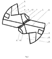
- a self-locking head-replaceable hard alloy drill bit comprises a cutter head and a cutter bar, in the view of the cutter head tip being upward, the upper part of the cutter head comprises a drill tip and a drilling body positioned below the drill tip, the cutter head is disposed at the upper end of the cutter bar, a cylindrical handle is disposed at the lower part of the cutter head, the outer diameter of the drilling body of the cutter head is larger than that of the cylindrical handle, a cylindrical handle holding slot or cylindrical handle holding hole is disposed at the upper end of the cutter bar, the cylindrical handle is mounted in the cylindrical handle holding slot or cylindrical handle holding hole, at least two cutter head notches are formed on the drilling body of the cutter head, each of the cutter head notches is formed by intersecting a first cutter head contact face and a second cutter head contact face, which are vertical or vertically oblique, the first cutter head contact faces are more close to the vertical central line of the drilling body of the cutter head than the second cutter head contact faces, the side edge of each first cutter head contact face distal to the corresponding
- the cutter head ridge edges and the inner surfaces of the protrusions are sequentially in non-contact fit, interference fit and non-interference fit during the assembly process, correspondingly, this effect is determined by the relative positional relation between the first cutter head contact faces and the cutter head ridge edges and the vertical central line of the drilling body and the relative position and distance between the protrusions, as well as the positional relation between the first cutter head contact faces and the inner surfaces of the protrusions and the positional relation between the second cutter head contact faces and the first lateral surfaces of the protrusions, such a structure can ensure self-locking, tight and stable assembly between the cutter head and the cutter bar and the transfer of vertical drilling force and torsion.
- the cutter head notches are two and symmetrically to each other relative to the vertical central line of the drilling body
- the protrusions are two and symmetrically to each other relative to the vertical central line of the cutter bar
- both the first cutter head contact faces and the second cutter head contact faces are a plane
- both the inner surfaces and the first lateral surfaces of the protrusions are a plane
- the distance between the two cutter head ridge edges is slightly greater than the shortest distance between the inner surfaces of the two protrusions.
- the first cutter head contact faces, the second cutter head contact faces and the inner surfaces and first lateral surfaces of the protrusions may be arc-shaped, but it is not preferred because the machining precision and machining cost of arc-shaped faces are higher.
- one of the specific preferred structures for realizing the assembly between the cutter head ridge edges and the inner surfaces of the two protrusions is that the distance between the two cutter head ridge edges is slightly greater than the shortest distance between the inner surfaces of the two protrusions, which is not always suitable for the case of more than two protrusions.
- the included angle between each second cutter head contact face and the horizontal direction is 45°-90°
- the upper part of each second cutter head contact face is more distal to the vertical central line of the drilling body of the cutter head than the lower part
- the included angle between each first lateral surface of the protrusions and the horizontal direction is 45°-90°.
- the first lateral surfaces of the protrusions receive the drilling torque from the second cutter head contact surfaces during the cutting process of the drill bit
- the upper end surfaces of the cutter bar is in close contact with the bottom of the drilling body of the cutter head when the drill bit is in self-locking state after assembly
- the end surfaces of the cutter bar receive the vertical drilling force from the bottom of the drilling body.
- the included angle between each second cutter head contact face and the horizontal direction is 65°, and the included angle between each first lateral surface of the protrusions and the horizontal direction is 65°.
- two loading/unloading clamp slots for mounting a loading/unloading tool are disposed on the upper margin of the drilling body of the cutter head and in the position beside the two cutter head notches.
- the included angle between the bottom of the loading/unloading clamp slots and the horizontal direction is 60°.
- the drill point angle of the drill tip at the top of the cutter head is 140°.
- spiral chip flutes are formed on both the cutter head and the cutter bar and communicate with each other.
- the spiral angle of the chip flutes is 25°.
- the first cutter head contact surfaces and second cutter head contact surfaces are disposed on the drilling body of the cutter head, the cutter head ridge edges are disposed on one side of the first cutter head contact surfaces, and the protrusions are disposed on the cutter bar, so that during the assembly process, the cutter head ridge edges are sequentially in non-contact fit, interference fit and non-interference fit with the inner surfaces of the protrusions, and after assembly, the first cutter head contact surfaces are in close contact with the inner surfaces of the protrusions and the vertically-oblique second cutter head contact surfaces are in close contact with the first lateral surfaces of the protrusions which are also vertically oblique at the same angle as the second cutter head contact surfaces, thereby realizing the self-locking function between the cutter head and the cutter bar and ensuring stable connection and reliable transmission of the cutter head and the cutter bar, in addition, the assembly/disassembly is very convenient and rapid without needing screws for fastening.
- the drilling torque applied to the cutter head is transferred to the cutter bar via the second cutter head contact surfaces, so that the fitting between the second contact surfaces of the cutter head and the first lateral surfaces of the protrusions and the fitting between the lower end surface of the drilling body of the cutter head and the upper end surfaces of the cutter bar are more tight during work of the cutter head and the cutter bar, thereby further realizing the self-locking function and ensuring high speed, high precision and less jump of the drill bit during the drilling process.
- the self-locking head-replaceable hard alloy drill bit of the present invention has unique self-locking function and the characteristics of simple structure, high reliability and high precision, has the advantages of high efficiency, high precision, low cost, rapid cutter head replacement, low cutting force, smooth chip removal and smooth cutting operation, and is widely applied to the high-speed high-feed machining of different types of holes.
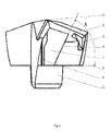
- the self-locking head-replaceable hard alloy drill bit of the present invention comprises a cutter head (6) and a cutter bar (12), in the view of the cutter head tip being upward, the upper part of the cutter head (6) comprises a drill tip (7) and a drilling body (not numbered in the figures) positioned below the drill tip (7), the drill point angle C of the drill tip (7) at the upper part of the cutter head (6) is 140°, the cutter head (6) is disposed at the upper end of the cutter bar (12), a cylindrical handle (1) is arranged at the lower part of the cutter head (6), the outer diameter of the drilling body of the cutter head (6) is larger than that of the cylindrical handle (1), a cylindrical handle holding slot (14) is disposed at the upper end faces (20) of the cutter bar (12), the cylindrical handle holding slot (14) is defined by the inner surface (15) of two upper end parts (19) of the cutter bar (12), the cylindrical handle holding slot (14) may be replaced by a cylindrical handle holding hole, the cylindrical handle (1) is
- reference horizontal line (8) is 65°, correspondingly, the included angle between the first lateral surface (21) of each protrusion (17) and the horizontal direction (i.e. reference horizontal line (8)) ranges from 45° to 90° and preferably equal to the included angle A, the included angle A may be another value in the range of 45° to 90°, the upper part of each second cutter head contact face (4) is more distal to the vertical central line of the drilling body of the cutter head (6) than the lower part, the first cutter head contact faces (5) are more close to the vertical central line of the drilling body of the cutter head (6) than the second cutter head contact faces (4), the side edge of each first cutter head contact face (5) distal to the corresponding second cutter head contact face (4) is bended towards the vertical central line of the drilling body of the cutter head (6) to form a cutter head ridge edge (10), the cutter head ridge edges (10) are arched edges, the distance between each cutter head ridge edge (10) and the vertical central line of the drilling body of the cutter head (6) is greater than the radi
- the included angle between the first cutter head contact face (5) and the second cutter head contact face (4) can be changed according to the actual needs, generally in the range of 60° to 90°, preferably 90°.
- Two loading/unloading clamp slots (3) are disposed at the upper edge of the drilling body of the cutter head (6) in the position beside the two cutter head notches (9) and used for mounting a loading/unloading tool, and the included angle B between the bottom surface of each clamp slot (3) and the horizontal direction (i.e. reference horizontal line (8)) is 60°.
- Spiral chip flutes (2) are disposed on the cutter head (6), a spiral chip flute (13) is disposed on the cutter bar (12), the spiral chip flutes (2) and the spiral chip flute (13) communicate to each other and both have the spiral angle of 25°.
- top surfaces (18) of the protrusions (17) are depicted, in which the height of the top surfaces (18) of the protrusions (17) is variable but needs to meet the fitting requirement of the protrusions (17) and the first cutter head contact faces (5).
- the top surfaces of the upper end parts (19) of the cutter bar (12) define upper end surfaces (20), and the upper end surfaces (20) are in close contact with the lower end surface of the drilling body of the cutter head (6) after the drill bit is assembled.
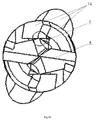
- the cylindrical handle (1) at the lower part of the cutter head (6) is put in the cylindrical handle holding slot (14) of the cutter bar (12), and the lower surface of the drilling body of the cutter head (6) is put on the upper end surfaces (20) of the cutter bar (12) in the position distal to the protrusions (17), and the cutter head ridge edges (10) are positioned on the inner side of the inner surfaces (16) of the protrusions (17); then the cutter head (6) is rotated clockwise using a loading/unloading tool (not shown in the figures) such that the cutter head ridge edges (10) are sequentially in non-contact fit, interference fit and non-interference fit with the inner surfaces (16) of the protrusions (17), the interference fit is depicted in Fig.12 and Fig.13 , upon interference fit, the contact between the cutter head (6) and the cutter bar (12) is closest, resulting in a need for
- the assembly of the cutter head (6) and the cutter bar (12) is completed.
- the cutter head (6) is rotated counter-clockwise using the loading/unloading tool, i.e., the cutter head (6) undergoes the reverse process to the foregoing, so that the cutter head ridge edges (10) and the inner surfaces (16) of the protrusions (17) are out of contact, as a result, the cutter head (6) and the cutter bar (12) are easily disassembled.
Landscapes
- Engineering & Computer Science (AREA)
- Mechanical Engineering (AREA)
- Drilling Tools (AREA)
Applications Claiming Priority (1)
| Application Number | Priority Date | Filing Date | Title |
|---|---|---|---|
| CN201510190598.XA CN104759664A (zh) | 2015-04-21 | 2015-04-21 | 自锁式可换头硬质合金钻头 |
Publications (1)
| Publication Number | Publication Date |
|---|---|
| EP3085480A1 true EP3085480A1 (fr) | 2016-10-26 |
Family
ID=53641939
Family Applications (1)
| Application Number | Title | Priority Date | Filing Date |
|---|---|---|---|
| EP16165921.4A Withdrawn EP3085480A1 (fr) | 2015-04-21 | 2016-04-19 | Foret en alliage dur à tête remplaçable autobloquante |
Country Status (3)
| Country | Link |
|---|---|
| US (1) | US10081066B2 (fr) |
| EP (1) | EP3085480A1 (fr) |
| CN (1) | CN104759664A (fr) |
Families Citing this family (26)
| Publication number | Priority date | Publication date | Assignee | Title |
|---|---|---|---|---|
| DE102013205889B3 (de) | 2013-04-03 | 2014-05-28 | Kennametal Inc. | Kupplungsteil, insbesondere Schneidkopf für ein Rotationswerkzeug sowie ein derartiges Rotationswerkzeug |
| DE102013220884B4 (de) | 2013-10-15 | 2022-02-17 | Kennametal Inc. | Modulares Trägerwerkzeug sowie Werkzeugkopf |
| DE102014206796B4 (de) | 2014-04-08 | 2020-10-15 | Kennametal Inc. | Rotationswerkzeug, insbesondere Bohrer sowie Schneidkopf für ein solches Rotationswerkzeug |
| DE102015106082A1 (de) * | 2014-04-24 | 2015-10-29 | Kennametal India Ltd. | Schneidwerkzeug mit auswechselbarem Schneideinsatz und geneigten Befestigungselementen |
| DE102015211744B4 (de) | 2015-06-24 | 2023-07-20 | Kennametal Inc. | Rotationswerkzeug, insbesondere Bohrer, und Schneidkopf für ein solches Rotationswerkzeug |
| US10071430B2 (en) | 2015-10-07 | 2018-09-11 | Kennametal Inc. | Cutting head, rotary tool and support for the rotary tool and for the accommodation of the cutting head |
| US9937567B2 (en) | 2015-10-07 | 2018-04-10 | Kennametal Inc. | Modular drill |
| USD798921S1 (en) | 2015-10-07 | 2017-10-03 | Kennametal Inc. | Cutting head for modular drill |
| USD798922S1 (en) | 2015-10-07 | 2017-10-03 | Kennametal Inc. | Cutting head for rotary drill |
| CN105328244A (zh) * | 2015-12-04 | 2016-02-17 | 苏州阿诺精密切削技术股份有限公司 | 交叉槽定位双螺钉锁紧齿冠钻头 |
| CN105290465A (zh) * | 2015-12-04 | 2016-02-03 | 苏州阿诺精密切削技术股份有限公司 | 交叉槽定位双螺钉锁紧齿冠钻刀片 |
| CN106475620B (zh) * | 2016-10-25 | 2020-05-05 | 株洲钻石切削刀具股份有限公司 | 可拆卸旋转刀具 |
| DE102017205166B4 (de) | 2017-03-27 | 2021-12-09 | Kennametal Inc. | Modulares Rotationswerkzeug und modulares Werkzeugsystem |
| DE102017212054B4 (de) | 2017-07-13 | 2019-02-21 | Kennametal Inc. | Verfahren zur Herstellung eines Schneidkopfes sowie Schneidkopf |
| US10799958B2 (en) | 2017-08-21 | 2020-10-13 | Kennametal Inc. | Modular rotary cutting tool |
| CN109590518B (zh) * | 2017-09-30 | 2024-06-21 | 成都新成量工具有限公司 | 自锁式快换钻 |
| CN112077370B (zh) | 2019-06-13 | 2024-10-01 | 肯纳金属印度有限公司 | 可转位钻头刀片 |
| CN111822757B (zh) * | 2020-07-27 | 2024-07-26 | 卑尔根精密工具(上海)有限公司 | 一种可换刀头式钻头 |
| CN115703157A (zh) | 2021-08-17 | 2023-02-17 | 肯纳金属印度有限公司 | 具有冷却剂系统的可转位钻头组件 |
| JP1715995S (ja) * | 2021-08-27 | 2022-05-27 | ドリルヘッド | |
| JP1715996S (ja) * | 2021-08-27 | 2022-05-27 | ドリルホルダ | |
| CN114147261A (zh) * | 2022-01-13 | 2022-03-08 | 成都邦普切削刀具股份有限公司 | 一种快速自锁式钻头及刀杆 |
| CN115090882B (zh) * | 2022-06-21 | 2023-12-01 | 昆山长鹰硬质材料科技股份有限公司 | 刀头半烧成型工艺及采用该工艺成型的刀头 |
| CN115026332B (zh) * | 2022-07-18 | 2024-08-20 | 杭州超尔切削工具有限公司 | 一种可换头式钻头 |
| US20240307978A1 (en) * | 2023-03-13 | 2024-09-19 | Kennametal Inc. | Modular rotary cutting tools |
| CN116652248A (zh) * | 2023-06-19 | 2023-08-29 | 苏州沃钛工业技术有限公司 | 全刀背旋插式换头钻 |
Citations (5)
| Publication number | Priority date | Publication date | Assignee | Title |
|---|---|---|---|---|
| US5957631A (en) | 1997-05-29 | 1999-09-28 | Iscar Ltd. | Cutting tool assembly and a replaceable cutting head for use therein |
| EP1273373A1 (fr) * | 2001-06-06 | 2003-01-08 | Sandvik Aktiebolag | Outil rotatif avec tête de coupe remplaçable |
| US7306410B2 (en) | 2000-09-01 | 2007-12-11 | Kennametal Inc. | Twist drill with a replaceable cutting insert and a rotary cutting tool with a replaceable cutting insert |
| WO2010105608A1 (fr) * | 2009-03-18 | 2010-09-23 | Gühring Ohg | Outil de coupe muni d'une plaquette de coupe interchangeable |
| EP2266735A1 (fr) * | 2009-06-23 | 2010-12-29 | Sandvik Intellectual Property AB | Outil de forage avec partie supérieure mobile |
Family Cites Families (20)
| Publication number | Priority date | Publication date | Assignee | Title |
|---|---|---|---|---|
| US7309196B2 (en) * | 2004-10-05 | 2007-12-18 | Kennametal Inc. | Modular drill |
| IL164888A (en) * | 2004-10-28 | 2009-07-20 | Iscar Ltd | Cutting tool and cutting head for it |
| JP4747282B2 (ja) * | 2005-03-29 | 2011-08-17 | 三菱マテリアル株式会社 | インサート着脱式ドリル |
| IL181296A0 (en) * | 2007-02-12 | 2007-07-04 | Iscar Ltd | Tool with releasably mounted self-clamping cutting head |
| DE102007044095A1 (de) * | 2007-09-14 | 2009-03-19 | Hartmetall-Werkzeugfabrik Paul Horn Gmbh | Bohrwerkzeug mit Bohrkrone |
| WO2008072840A2 (fr) * | 2007-11-05 | 2008-06-19 | Taegutec. Ltd. | Fraise |
| SE532280C2 (sv) * | 2008-04-14 | 2009-12-01 | Seco Tools Ab | Verktyg, verktygskropp och skärhuvud |
| SE533652C2 (sv) * | 2008-04-14 | 2010-11-23 | Seco Tools Ab | Verktyg för roterande skärande bearbetning med utbytbart skärhuvud |
| US7625161B1 (en) * | 2008-08-08 | 2009-12-01 | Kennametal Inc. | Rotary cutting tool assembly and cutting insert and tool shank therefor |
| DE102009013580A1 (de) * | 2009-03-19 | 2010-09-23 | EMUGE-Werk Richard Glimpel GmbH & Co. KG Fabrik für Präzisionswerkzeuge | Modularer Bohrer |
| SE533851C2 (sv) * | 2009-06-23 | 2011-02-08 | Sandvik Intellectual Property | Borrverktyg för spånavskiljande bearbetning samt löstopp och grundkropp härför |
| SE533853C2 (sv) * | 2009-06-23 | 2011-02-08 | Sandvik Intellectual Property | Borrverktyg för spånavskiljande bearbetning samt löstopp härför |
| JP4954331B2 (ja) * | 2009-12-08 | 2012-06-13 | オーエスジー株式会社 | スローアウェイ式回転工具 |
| JP4870228B2 (ja) * | 2009-12-08 | 2012-02-08 | オーエスジー株式会社 | スローアウェイ式回転工具 |
| DE102010026271B4 (de) * | 2010-07-06 | 2019-02-14 | Kennametal Inc. | Bohrwerkzeug |
| DE102012212146B4 (de) * | 2012-07-11 | 2024-02-01 | Kennametal Inc. | Kupplungsstelle für ein modulares Rotationswerkzeug sowie Werkzeugkopf und Träger für ein solches modulares Rotationswerkzeug |
| WO2014103972A1 (fr) * | 2012-12-28 | 2014-07-03 | 京セラ株式会社 | Mèche et procédé pour fabriquer un produit coupé l'utilisant |
| DE102013220884B4 (de) * | 2013-10-15 | 2022-02-17 | Kennametal Inc. | Modulares Trägerwerkzeug sowie Werkzeugkopf |
| KR101509954B1 (ko) * | 2013-10-29 | 2015-04-07 | 한국야금 주식회사 | 절삭 인서트 및 인덱서블 드릴 |
| CN204545517U (zh) * | 2015-04-21 | 2015-08-12 | 成都锋宜精密工具制造有限公司 | 自锁式可换头硬质合金钻头 |
-
2015
- 2015-04-21 CN CN201510190598.XA patent/CN104759664A/zh active Pending
-
2016
- 2016-04-19 EP EP16165921.4A patent/EP3085480A1/fr not_active Withdrawn
- 2016-04-20 US US15/134,018 patent/US10081066B2/en active Active
Patent Citations (5)
| Publication number | Priority date | Publication date | Assignee | Title |
|---|---|---|---|---|
| US5957631A (en) | 1997-05-29 | 1999-09-28 | Iscar Ltd. | Cutting tool assembly and a replaceable cutting head for use therein |
| US7306410B2 (en) | 2000-09-01 | 2007-12-11 | Kennametal Inc. | Twist drill with a replaceable cutting insert and a rotary cutting tool with a replaceable cutting insert |
| EP1273373A1 (fr) * | 2001-06-06 | 2003-01-08 | Sandvik Aktiebolag | Outil rotatif avec tête de coupe remplaçable |
| WO2010105608A1 (fr) * | 2009-03-18 | 2010-09-23 | Gühring Ohg | Outil de coupe muni d'une plaquette de coupe interchangeable |
| EP2266735A1 (fr) * | 2009-06-23 | 2010-12-29 | Sandvik Intellectual Property AB | Outil de forage avec partie supérieure mobile |
Also Published As
| Publication number | Publication date |
|---|---|
| US10081066B2 (en) | 2018-09-25 |
| CN104759664A (zh) | 2015-07-08 |
| US20160311035A1 (en) | 2016-10-27 |
Similar Documents
| Publication | Publication Date | Title |
|---|---|---|
| EP3085480A1 (fr) | Foret en alliage dur à tête remplaçable autobloquante | |
| EP1296791B1 (fr) | Outil rotatif comportant une pointe interchangeable au niveau de l'extremite libre d'enlevement de copeaux de l'outil | |
| JPS6133806A (ja) | ドリル | |
| US4076443A (en) | Cutting tool assembly | |
| JP6803472B1 (ja) | 切削インサートおよび切削工具 | |
| JP2017510469A (ja) | 切削工具、及び切削工具のためのちょうど4つの刃部を有する切削インサート | |
| US11446743B2 (en) | Side-lock modular drill with spring-assisted bump-off | |
| CN108687385A (zh) | 前装载、侧激活的模块化钻头 | |
| CN205218135U (zh) | 一种微型钻头 | |
| US20140308086A1 (en) | Drill head | |
| JP2009255202A (ja) | 深穴切削用ドリルヘッド | |
| JPS5946723B2 (ja) | 穿孔工具 | |
| EP2896478A1 (fr) | Outil de forage | |
| US4861048A (en) | Jaw assembly for lathe chuck | |
| US20210394281A1 (en) | Drill and insert for drill having improved centering capability and cutting performance | |
| CN205218134U (zh) | 一种印刷电路板用钻头 | |
| EP4435373A1 (fr) | Procédé de fabrication d'une equerre fixe | |
| KR101032667B1 (ko) | 센터링용 드릴 | |
| CN101700579B (zh) | 高精度孔加工钻镗刀具 | |
| EP3345705A1 (fr) | Manche pour outil de forage, outil de forage et procédé de fabrication d'un outil de forage | |
| CN214815126U (zh) | 带中心钻成型刀 | |
| CN106563839A (zh) | 一种三槽钻扩孔台阶钻 | |
| CN205551567U (zh) | 钻头打孔一体成型倒角器 | |
| CN209094627U (zh) | 一种s型螺旋扁钻尖的可更换钻头 | |
| CN119304243B (zh) | 一种高精度球头铣刀 |
Legal Events
| Date | Code | Title | Description |
|---|---|---|---|
| PUAI | Public reference made under article 153(3) epc to a published international application that has entered the european phase |
Free format text: ORIGINAL CODE: 0009012 |
|
| AK | Designated contracting states |
Kind code of ref document: A1 Designated state(s): AL AT BE BG CH CY CZ DE DK EE ES FI FR GB GR HR HU IE IS IT LI LT LU LV MC MK MT NL NO PL PT RO RS SE SI SK SM TR |
|
| AX | Request for extension of the european patent |
Extension state: BA ME |
|
| RIN1 | Information on inventor provided before grant (corrected) |
Inventor name: PENG, HAO Inventor name: PENG, LUGUI |
|
| 17P | Request for examination filed |
Effective date: 20170112 |
|
| RBV | Designated contracting states (corrected) |
Designated state(s): AL AT BE BG CH CY CZ DE DK EE ES FI FR GB GR HR HU IE IS IT LI LT LU LV MC MK MT NL NO PL PT RO RS SE SI SK SM TR |
|
| RIN1 | Information on inventor provided before grant (corrected) |
Inventor name: PENG, HAO Inventor name: PENG, LUGUI |
|
| STAA | Information on the status of an ep patent application or granted ep patent |
Free format text: STATUS: THE APPLICATION IS DEEMED TO BE WITHDRAWN |
|
| 18D | Application deemed to be withdrawn |
Effective date: 20181101 |