EP3085487B1 - Appareil de découpe d'objet fragile et procédé de découpage associé - Google Patents
Appareil de découpe d'objet fragile et procédé de découpage associé Download PDFInfo
- Publication number
- EP3085487B1 EP3085487B1 EP15166423.2A EP15166423A EP3085487B1 EP 3085487 B1 EP3085487 B1 EP 3085487B1 EP 15166423 A EP15166423 A EP 15166423A EP 3085487 B1 EP3085487 B1 EP 3085487B1
- Authority
- EP
- European Patent Office
- Prior art keywords
- laser
- heating
- scribing
- brittle object
- optical path
- Prior art date
- Legal status (The legal status is an assumption and is not a legal conclusion. Google has not performed a legal analysis and makes no representation as to the accuracy of the status listed.)
- Not-in-force
Links
Images


Classifications
-
- B—PERFORMING OPERATIONS; TRANSPORTING
- B23—MACHINE TOOLS; METAL-WORKING NOT OTHERWISE PROVIDED FOR
- B23K—SOLDERING OR UNSOLDERING; WELDING; CLADDING OR PLATING BY SOLDERING OR WELDING; CUTTING BY APPLYING HEAT LOCALLY, e.g. FLAME CUTTING; WORKING BY LASER BEAM
- B23K26/00—Working by laser beam, e.g. welding, cutting or boring
- B23K26/02—Positioning or observing the workpiece, e.g. with respect to the point of impact; Aligning, aiming or focusing the laser beam
- B23K26/06—Shaping the laser beam, e.g. by masks or multi-focusing
- B23K26/0604—Shaping the laser beam, e.g. by masks or multi-focusing by a combination of beams
- B23K26/0608—Shaping the laser beam, e.g. by masks or multi-focusing by a combination of beams in the same heat affected zone [HAZ]
-
- B—PERFORMING OPERATIONS; TRANSPORTING
- B23—MACHINE TOOLS; METAL-WORKING NOT OTHERWISE PROVIDED FOR
- B23K—SOLDERING OR UNSOLDERING; WELDING; CLADDING OR PLATING BY SOLDERING OR WELDING; CUTTING BY APPLYING HEAT LOCALLY, e.g. FLAME CUTTING; WORKING BY LASER BEAM
- B23K26/00—Working by laser beam, e.g. welding, cutting or boring
- B23K26/08—Devices involving relative movement between laser beam and workpiece
- B23K26/083—Devices involving movement of the workpiece in at least one axial direction
- B23K26/0853—Devices involving movement of the workpiece in at least two axial directions, e.g. in a plane
-
- B—PERFORMING OPERATIONS; TRANSPORTING
- B23—MACHINE TOOLS; METAL-WORKING NOT OTHERWISE PROVIDED FOR
- B23K—SOLDERING OR UNSOLDERING; WELDING; CLADDING OR PLATING BY SOLDERING OR WELDING; CUTTING BY APPLYING HEAT LOCALLY, e.g. FLAME CUTTING; WORKING BY LASER BEAM
- B23K26/00—Working by laser beam, e.g. welding, cutting or boring
- B23K26/14—Working by laser beam, e.g. welding, cutting or boring using a fluid stream, e.g. a jet of gas, in conjunction with the laser beam; Nozzles therefor
- B23K26/146—Working by laser beam, e.g. welding, cutting or boring using a fluid stream, e.g. a jet of gas, in conjunction with the laser beam; Nozzles therefor the fluid stream containing a liquid
-
- B—PERFORMING OPERATIONS; TRANSPORTING
- B23—MACHINE TOOLS; METAL-WORKING NOT OTHERWISE PROVIDED FOR
- B23K—SOLDERING OR UNSOLDERING; WELDING; CLADDING OR PLATING BY SOLDERING OR WELDING; CUTTING BY APPLYING HEAT LOCALLY, e.g. FLAME CUTTING; WORKING BY LASER BEAM
- B23K26/00—Working by laser beam, e.g. welding, cutting or boring
- B23K26/352—Working by laser beam, e.g. welding, cutting or boring for surface treatment
- B23K26/359—Working by laser beam, e.g. welding, cutting or boring for surface treatment by providing a line or line pattern, e.g. a dotted break initiation line
-
- B—PERFORMING OPERATIONS; TRANSPORTING
- B23—MACHINE TOOLS; METAL-WORKING NOT OTHERWISE PROVIDED FOR
- B23K—SOLDERING OR UNSOLDERING; WELDING; CLADDING OR PLATING BY SOLDERING OR WELDING; CUTTING BY APPLYING HEAT LOCALLY, e.g. FLAME CUTTING; WORKING BY LASER BEAM
- B23K26/00—Working by laser beam, e.g. welding, cutting or boring
- B23K26/36—Removing material
- B23K26/38—Removing material by boring or cutting
-
- B—PERFORMING OPERATIONS; TRANSPORTING
- B23—MACHINE TOOLS; METAL-WORKING NOT OTHERWISE PROVIDED FOR
- B23K—SOLDERING OR UNSOLDERING; WELDING; CLADDING OR PLATING BY SOLDERING OR WELDING; CUTTING BY APPLYING HEAT LOCALLY, e.g. FLAME CUTTING; WORKING BY LASER BEAM
- B23K26/00—Working by laser beam, e.g. welding, cutting or boring
- B23K26/36—Removing material
- B23K26/40—Removing material taking account of the properties of the material involved
-
- B—PERFORMING OPERATIONS; TRANSPORTING
- B28—WORKING CEMENT, CLAY, OR STONE
- B28D—WORKING STONE OR STONE-LIKE MATERIALS
- B28D1/00—Working stone or stone-like materials, e.g. brick, concrete or glass, not provided for elsewhere; Machines, devices, tools therefor
- B28D1/22—Working stone or stone-like materials, e.g. brick, concrete or glass, not provided for elsewhere; Machines, devices, tools therefor by cutting, e.g. incising
- B28D1/221—Working stone or stone-like materials, e.g. brick, concrete or glass, not provided for elsewhere; Machines, devices, tools therefor by cutting, e.g. incising by thermic methods
-
- B—PERFORMING OPERATIONS; TRANSPORTING
- B28—WORKING CEMENT, CLAY, OR STONE
- B28D—WORKING STONE OR STONE-LIKE MATERIALS
- B28D7/00—Accessories specially adapted for use with machines or devices of the preceding groups
- B28D7/005—Devices for the automatic drive or the program control of the machines
-
- B—PERFORMING OPERATIONS; TRANSPORTING
- B28—WORKING CEMENT, CLAY, OR STONE
- B28D—WORKING STONE OR STONE-LIKE MATERIALS
- B28D7/00—Accessories specially adapted for use with machines or devices of the preceding groups
- B28D7/02—Accessories specially adapted for use with machines or devices of the preceding groups for removing or laying dust, e.g. by spraying liquids; for cooling work
-
- C—CHEMISTRY; METALLURGY
- C03—GLASS; MINERAL OR SLAG WOOL
- C03B—MANUFACTURE, SHAPING, OR SUPPLEMENTARY PROCESSES
- C03B33/00—Severing cooled glass
- C03B33/09—Severing cooled glass by thermal shock
- C03B33/091—Severing cooled glass by thermal shock using at least one focussed radiation beam, e.g. laser beam
- C03B33/093—Severing cooled glass by thermal shock using at least one focussed radiation beam, e.g. laser beam using two or more focussed radiation beams
-
- B—PERFORMING OPERATIONS; TRANSPORTING
- B23—MACHINE TOOLS; METAL-WORKING NOT OTHERWISE PROVIDED FOR
- B23K—SOLDERING OR UNSOLDERING; WELDING; CLADDING OR PLATING BY SOLDERING OR WELDING; CUTTING BY APPLYING HEAT LOCALLY, e.g. FLAME CUTTING; WORKING BY LASER BEAM
- B23K2101/00—Articles made by soldering, welding or cutting
- B23K2101/36—Electric or electronic devices
- B23K2101/40—Semiconductor devices
-
- B—PERFORMING OPERATIONS; TRANSPORTING
- B23—MACHINE TOOLS; METAL-WORKING NOT OTHERWISE PROVIDED FOR
- B23K—SOLDERING OR UNSOLDERING; WELDING; CLADDING OR PLATING BY SOLDERING OR WELDING; CUTTING BY APPLYING HEAT LOCALLY, e.g. FLAME CUTTING; WORKING BY LASER BEAM
- B23K2103/00—Materials to be soldered, welded or cut
- B23K2103/50—Inorganic materials other than metals or composite materials
- B23K2103/52—Ceramics
-
- B—PERFORMING OPERATIONS; TRANSPORTING
- B23—MACHINE TOOLS; METAL-WORKING NOT OTHERWISE PROVIDED FOR
- B23K—SOLDERING OR UNSOLDERING; WELDING; CLADDING OR PLATING BY SOLDERING OR WELDING; CUTTING BY APPLYING HEAT LOCALLY, e.g. FLAME CUTTING; WORKING BY LASER BEAM
- B23K2103/00—Materials to be soldered, welded or cut
- B23K2103/50—Inorganic materials other than metals or composite materials
- B23K2103/54—Glass
Definitions
- the present invention relates to a cutting apparatus and cutting method thereof, in particular to a brittle object cutting apparatus and cutting method thereof, which apply laser to generate thermally-induced mechanical stress in order to cut brittle objects (see e.g. US 2008035617 ).
- the depth of the notch must be at least one-third of the flat material thickness.
- the notch can be applied mechanically or by means of lasers. Particularly for dicing chips from substrates (wafers), laser methods that create a notch by ablation into the material are increasingly being used.
- the notches are typically only a few ⁇ m wide and have an approximate depth of one third the flat material thickness.
- the notch depth is produced proportionately to the total thickness of the flat material, depending on its brittleness. It is disadvantageous that every volume of removed material potentially contributes to the microscopic contamination of the material being processed. Since the aspect ratio between notch width and notch depth is critical to all these laser processes, complex apparatuses are needed and the notch is created relatively slowly. Deep notches for thick wafers therefore require increasingly more process time.
- the wafer is completely cut by applying mechanical (impulse) energy or forces, for example tensile force (stretching of films), bending forces (breaking over ridges) or a combination thereof.
- mechanical energy or forces for example tensile force (stretching of films), bending forces (breaking over ridges) or a combination thereof.
- a known method is to produce a mechanically-induced initial crack, which is subsequently propagated through the flat material by means of thermally-induced mechanical stresses.
- Such a method thermal laser separation, TLS
- TLS thermal laser separation
- the present invention provides a brittle object cutting apparatus for cutting a brittle object, comprising: a scribing laser unit, configured to emit a scribing laser on the brittle object; a first heating laser unit, configured to emit a first heating laser; a second heating laser unit, configured to emit a second heating laser, wherein the first heating laser and the second heating laser respectively located on opposite sides of the scribing laser; two cooling units, configured to provide a coolant to cool the brittle object, one of the two cooling units disposed at a side of the first heating laser and opposite to the scribing laser so as to cool the brittle object irradiated by the first heating laser, another one of the two cooling units disposed at a side of the second heating laser and opposite to the scribing laser so as to cool the brittle object irradiated by the second heating laser; and a processing module, configured to selectively control the scribing laser unit, the first heating laser
- a machining direction of the scribing laser, the first heating laser and the coolant may be opposite to a machining direction of the scribing laser, the second heating laser and the coolant.
- the scribing laser may scribe the plurality of first-axis dividing lines with a predetermined distance, originated from an edge of the brittle object, on the brittle object, and the scribing laser scribes the plurality of second-axis dividing lines completely or only scribes intersections between the plurality of first-axis and second-axis dividing lines with the predetermined distance on the brittle object.
- the present invention further provides brittle object cutting apparatus for cutting a brittle object, comprising: a scribing laser unit, configured to emit a scribing laser on the brittle object via a scribing optical path; a heating laser unit, configured to emit a heating laser; a first light guide unit, configured to guide the heating laser to heat the brittle object via a first heating optical path or to pass the first light guide unit, or configured to guide a portion of the heating laser to pass the first heating optical path and another portion of the heating laser to pass through the first light guide unit; a second light guide unit, configured to guide the heating laser passed from the first light guide unit to heat the brittle object via a second heating optical path, wherein the first heating optical path and the second heating optical path respectively located on opposite sides of the scribing optical path when the first heating optical path, the second heating optical path and the scribing optical path are emitted on the brittle object; two cooling units, configured to provide a scribing laser
- a machining direction of the scribing laser in the scribing optical path, the heating laser in the first heating optical path and the coolant may be opposite to a machining direction of the scribing laser in the scribing optical path, the heating laser in the second heating optical path and the coolant.
- the scribing laser may scribe the plurality of first-axis dividing lines with a predetermined distance, originated from an edge of the brittle object, on the brittle object, and the scribing laser scribes the plurality of second-axis dividing lines completely or only scribes intersections between the plurality of first-axis and second-axis dividing lines with the predetermined distance on the brittle object.
- the present invention further provides a method of cutting a brittle object with a plurality of first-axis and second-axis dividing lines, comprising steps of: providing a scribing laser unit to emit a scribing laser; providing a first heating laser unit to emit a first heating laser; providing a second heating laser unit to emit a second heating laser; scribing the brittle object by emitting the scribing laser along one of the plurality of first-axis and second-axis dividing lines on the brittle object; and heating the brittle object by selectively applying the first heating laser or the second heating laser and cooling the heated brittle object via a coolant providing by a cooling unit right after heating by the first heating laser or the second heating laser along one of the plurality of first-axis and second-axis dividing lines, wherein the scribing step, and the heating step and the cooling step are performed in the same machining operation.
- the method of cutting a brittle object with a plurality of dividing lines may further comprise the step of: adjusting emitting positions of the first heating laser and the second heating laser, respectively, on the brittle object to be at lateral sides of an emitting position of the scribing laser on the brittle object.
- a machining direction of the scribing laser, the first heating laser and the coolant may be opposite to a machining direction of the scribing laser, the second heating laser and the coolant.
- the method of cutting a brittle object with a plurality of dividing lines may further comprise the step of: controlling the scribing laser to scribe the plurality of first-axis dividing lines in a with a predetermined distance, originated from an edge of the brittle object, on the brittle object.
- the method of cutting a brittle object with a plurality of dividing lines may further comprise the step of: controlling the scribing laser to scribe the plurality of second-axis dividing lines completely or only scribes intersections between the plurality of first-axis dividing lines and the plurality of second-axis dividing lines with the predetermined distance on the brittle object.
- the brittle object is embodied as wafer, such as sapphire wafers.
- other brittle objects such as glass, silicon, gallium arsenide or ceramics, may be applied.
- the following preferred embodiments should not be construed as limitations to the present invention.
- the plurality of dividing lines on the brittle objects may comprise a plurality of first-axis dividing lines and a plurality of second-axis dividing lines.
- the first-axis may be perpendicular to the second-axis.
- the brittle object cutting apparatus according to the present invention individually cuts along the plurality of first-axis dividing lines while continuously moving the brittle object back and forth, i.e. forward and reverse direction. Then, the brittle object cutting apparatus according to the present invention subsequently and individually cuts along the plurality of second-axis dividing lines while continuously moving the brittle object back and forth, thereby dicing the brittle object.
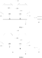
- the brittle object cutting apparatus for cutting a brittle object comprises a first heating laser unit 11, a second heating laser unit 12, a scribing laser unit 13, two cooling units 14A and 14B, and a processing module 15.
- the first heating laser unit 11 and the second heating laser unit 12 may be a CO 2 laser, and the first heating laser unit 11 may emit a first heating laser 111 and the second heating laser unit 12 may emit a second heating laser 121.
- the scribing laser unit 13 may be a UV laser, and the scribing laser unit 13 may emit a scribing laser 131 on the brittle object 9, wherein the first heating laser 111 and the second heating laser 121 respectively located on opposite sides of the scribing laser 131 when the first heating laser 111, the second heating laser 121 and the scribing laser 131 are emitted on the brittle object 9. That is, the first heating laser 111 is located behind the scribing laser 131 while machining in the forward direction, however, the second heating laser 121 is located behind the scribing laser 131 while machining in the reverse direction.
- the cooling units 14 may provide a coolant to cool the brittle object 9; wherein one of the two cooling units 14A disposed at a side of the first heating laser 111 and opposite to the scribing laser 131 so as to cool the brittle object 9 irradiated by the first heating laser 111, another one of the two cooling units 14B disposed at a side of the second heating laser 121 and opposite to the scribing laser 131 so as to cool the brittle object 9 irradiated by the second heating laser 121.
- the processing module 15 may be a central processing unit (CPU) or a microcontroller unit (MCU).
- the processing module 15 selectively controls the scribing laser unit 13, the first heating laser unit 11 and the cooling unit 14A, or controls the scribing laser unit 13, the second heating laser unit 12 and the another cooling unit 14B to perform a machining operation.
- a machining operation e.g. in machining along a first axis dividing line
- the scribing laser 131, the first heating laser 111 and the coolant are sequentially applied along one of the plurality of dividing lines on the brittle object 9; or the scribing laser 131, the second heating laser 121 and the coolant are sequentially applied along one of the plurality of dividing lines on the brittle object 9.
- the first heating laser unit 11 and the cooling unit 14A, or the second heating laser unit 12 and the another cooling unit 14B simultaneously heats and cools the brittle object, respectively.
- the brittle object cutting apparatus may further comprise guiding units to guide light, focusing lens, a supporting unit to move the brittle object 9, or a driving unit, which will not be further described here.
- the supporting unit for moving the brittle object 9, or the driving unit thereof are controlled be the processing unit 15, so as to move the brittle object 9 in a first axis or a second axis, or to rotate around a rotation axis.
- the focusing lens, mounted on a third axis may also be controlled by the processing unit 15, so as to focus the laser on the surface of the brittle object 9.
- the first axis, the second axis, and the rotation axis are together.
- the third axis is separated from the first axis, the second axis and the rotation axis.
- X-axis there may be X-axis, Y-axis with mounted on this stage C axis to rotate (align) the brittle object along dividing lines, and the Z-axis, in which X-axis and Y-axis are used for moving the brittle objects.
- Z-axis is used to move the objective lenses in order to focus the laser on the surface of the brittle object, instead of moving the brittle object closer or far from the focusing lens. That is, Z-axis is to keep the lens in the housing and change the focus, i.e. working distance (WD) between the lens and the brittle object.
- WD working distance
- the rotation axis is mounted on the X, Y stage for rotating/aligning the brittle object along the dividing lines, turning the brittle object on 90 degrees after the first direction, e.g. forward direction (+), has been cut, and being vacuum chuck also.
- the processing module 15 controls the scribing laser unit 13 to scribe, and the first heating laser unit 11 and the cooling unit 14A to perform the heating and cooling process. Then, when the brittle object cutting apparatus cuts the brittle object 9 along first axis dividing lines in the reverse direction (-), the processing module 15 controls the scribing laser unit 13 to scribe, the second heating laser unit 12 and the another cooling unit 14B to perform the heating and cooling process.
- the brittle object cutting apparatus cuts the brittle object 9 along the second-axis dividing lines
- the process is similar to those cutting along the first-axis dividing lines and will be further described hereinafter. Therefore, after the brittle object cutting apparatus cuts the brittle object 9 in the forward direction by using the scribing laser unit 13, the first heating laser unit 11 and the cooling unit 14A, sequentially, the scribing laser unit 13, the second heating laser unit 12 and the another cooling unit 14B may be directly applied in the reverse direction in the machining process, thereby reducing the machining time as moving the brittle objects.
- the scribing laser unit 13 and the first heating laser unit 11 are applied simultaneously, and the cooling unit 14A cools the heated brittle object right after heating by the first heating laser unit 11.
- the scribing laser unit 13 and the second heating laser unit 12 are applied simultaneously, and the another cooling unit 14B cools the heated brittle object right after heating by the second heating laser unit 12. Therefore, the brittle object cutting apparatus according to the present invention may solve the problems of poor edge quality or low precision due to deviation in prior art.
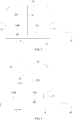
- the brittle object cutting apparatus comprises a heating laser unit 21, a first light guide unit 22, a second light guide unit 23, a scribing laser unit 13, two cooling units 14A, 14B and a processing module 15.
- the heating laser unit 21 may emit a heating laser.
- the first light guide unit 22 may be movable reflective mirror, or the first light guide unit 22 may be a splitter. Wherein, the detailed description of the first light guide unit 22 being embodied as splitter will be further described in the next embodiment.
- the first light guide unit 22 guides the heating laser to heat the brittle object 9 via a first heating optical path 221 or to pass the laser radiation to the second light guide unit 23 when the first light guide unit 22 is moved aside.
- the second light guide unit 23 guides the heating laser passed from the heating laser unit 21 to heat the brittle object 9 via a second heating optical path 231.
- the scribing laser unit 13 may emit a scribing laser on the brittle object 9 via a scribing optical path 132, wherein the first heating optical path 221 and the second heating optical path 231 respectively located on opposite sides of the scribing optical path 132, i.e.
- the two cooling units 14A, 14B may provide a coolant to cool the brittle object 9, which is similar to the previous embodiment and will not be further described here. That is, the first heating optical path 221 is located behind the scribing optical path 132 while machining in a forward direction (+), and the coolant is located behind the first heating optical path 221, however, the second heating optical path 231 is located behind the scribing optical path 132 while machining in a reverse direction (-), and the coolant is located behind the second heating optical path 231.
- the processing module 15 may selectively control the heating laser unit 21, the first light guide unit 22, the scribing laser unit 13 and the two cooling units 14A, 14B to perform a machining operation.
- the scribing laser in the scribing optical path 132, the heating laser in the first heating optical path 221 and the coolant are sequentially applied along one of a plurality of dividing lines, such as first-axis dividing lines, on the brittle object 9; or the scribing laser in the scribing optical path 132, the heating laser in the second heating optical path 231 and the coolant are sequentially applied along one of a plurality of dividing lines, such as second-axis dividing lines, on the brittle object 9.
- the heating laser in the first heating optical path 221 and the coolant, or the heating laser in the second heating optical path 231 and the coolant processes on the brittle subject simultaneously.
- the processing module 15 controls the first light guide unit 22 to change the original optical path of the heating laser unit 21 so as to emit on the brittle object 9 via the first heating optical path 221.
- the brittle object cutting apparatus performs the machining process by sequentially applying the scribing laser in the scribing optical path 132 to scribe, and using the heating laser in the first heating optical path 221 and the coolant to heat and cool the brittle object, respectively, along the first-axis dividing lines.
- the processing module 15 controls the first light guide unit 22 to move it aside without changing the original optical path of the heating laser unit 21 so that the heating laser from the heating laser unit 21 may be received by the second light guide unit 23. Therefore, the second light guide unit 23 may change the original optical path of the heating laser unit 21 so as to emit on the brittle object 9 via the second heating optical path 231.
- the brittle object cutting apparatus performs the machining process by sequentially applying the scribing laser in the scribing optical path 132 to scribe, and using the heating laser in the second heating optical path 231 and the coolant to heat and cool the brittle object, respectively, along the first-axis dividing lines.
- the heating laser in the first heating optical path 221 and the coolant the heating laser from the second heating optical path 231 and the coolant from the another cooling unit 14B may be directly applied to heat and cool the brittle object 9, so as to cut the brittle object 9 in the reverse direction, thereby reducing the machining time while using only one heating laser unit.
- the first light guide unit 22 is embodied as a splitter.
- the transmittance and reflectance of the splitter are 50% and 50%, respectively.
- the transmittance and reflectance of the splitter may be varied depending on the machining process or the configuration designed by designers. For instance, the transmittance and reflectance of the splitter may respectively be 40% and 60%, 30% and 70%, etc.
- the configuration of the components in the apparatus is similar to the previous embodiment and will not be further described herein.
- a movable blocking unit 24 in both the first heating optical path 221 and the second heating optical path 231, respectively.
- the movable blocking units 24 selectively blocks the heating lasers either in the first heating optical path 221 or in the second heating optical path 231 under the control of the processing module 15.
- the processing module 15 controls the blocking unit 24 in the second heating optical path 231 moving to block the heating laser in the second heating optical path 231, so that only the heating laser in the first heating optical path 221 irradiates on the brittle object 9.
- the brittle object cutting apparatus performs the machining process by sequentially applying the scribing laser in the scribing optical path 132 to scribe, and using the heating laser in the first heating optical path 221 and the coolant to heat and cool the brittle object, respectively, along the first-axis dividing lines.
- the processing module 15 controls the blocking unit 24 in the first heating optical path 221 moving to block the heating laser in the first heating optical path 221, so that only the heating laser in the second heating optical path 231 irradiates on the brittle object 9.
- the brittle object cutting apparatus performs the machining process by sequentially applying the scribing laser in the scribing optical path 132 to scribe, and using the heating laser in the second heating optical path 231 and the coolant to heat and cool the brittle object, respectively, along the first-axis dividing lines.
- the method of cutting brittle object in the embodiment may be applied in the brittle object cutting apparatus according to the first embodiment of the present invention.
- the method of cutting brittle object may be applied to the brittle object cutting apparatus according to the second and the third embodiments of the present invention as well.
- the method of cutting a brittle object comprises the following steps of:
- the notches generating by the scribing laser unit 13 may preferably have a width of 2-10 ⁇ m.
- the depth of the notches may be less than 1/10 of the thickness of the brittle object 9, for instance, 3-15 ⁇ m for the 90-130 um wafer thickness.
- the cutting velocity lies in the range of 100-300 mm/s, or even faster.
- the machining parameters above of the brittle object cutting apparatus according to the present invention is only for illustrations of a few aspects according to the present invention, and should not be construed as limitations.
- the scribing laser 131 from the scribing laser unit 13 only scribes a predetermined distance D, which originated from an edge of the brittle object 9, on the brittle object 9.
- the predetermined distance D may range from 30 ⁇ m to 1000 ⁇ m.
- the scribing laser unit 13 may scribe the dividing lines into two distinct scribing patterns. As shown in FIG. 9(a) , in an embodiment, the scribing laser unit 13 scribes along the second-axis dividing lines on the brittle object 9 entirely and completely. Contrarily, as shown in FIG.
- the scribing laser unit 13 only scribes intersections between the plurality of dividing lines with the predetermined distance D, 5-100 um for instance, along the second-axis on the brittle object.
- the center of the predetermined distance D may be the intersection between the plurality of first-axis dividing lines and the plurality of second-axis dividing lines.
- the second-axis dividing lines may be cut after all the first-axis dividing lines have been cut.
- the machining process of both the first-axis dividing lines and the second-axis dividing lines may be started in either forward direction or reverse direction.
- the brittle object cutting apparatus and cutting method thereof according to the present invention may cut each the first-axis dividing lines sequentially or randomly. After each of the first-axis dividing lines is cut, the brittle object 9 may be rotated, e.g. 90 degrees, and each of the second-axis dividing lines may further be sequentially or randomly cut.
- both the first-axis dividing lines and the second-axis dividing lines is sequentially cut as an example, and should not be construed as limitations.
Landscapes
- Engineering & Computer Science (AREA)
- Physics & Mathematics (AREA)
- Optics & Photonics (AREA)
- Mechanical Engineering (AREA)
- Plasma & Fusion (AREA)
- Toxicology (AREA)
- Health & Medical Sciences (AREA)
- Chemical & Material Sciences (AREA)
- Thermal Sciences (AREA)
- Materials Engineering (AREA)
- Organic Chemistry (AREA)
- Mining & Mineral Resources (AREA)
- Processing Of Stones Or Stones Resemblance Materials (AREA)
- Re-Forming, After-Treatment, Cutting And Transporting Of Glass Products (AREA)
- Laser Beam Processing (AREA)
Claims (11)
- Appareil coupant d'objet fragile prévu pour couper un objet fragile (9) comprenant :une unité laser de traçage (13), conçue pour émettre un rayonnement laser de traçage (131) sur l'objet fragile (9),une première unité laser de chauffage (11), configurée pour émettre un premier rayonnement laser de chauffage (111) ;une seconde unité laser de chauffage (12), configurée pour émettre un second rayonnement laser de chauffage (121),
le premier rayonnement laser de chauffage (111) et le second rayonnement de chauffage (121) étant respectivement situés sur des côtés opposés du rayonnement laser de traçage (131) ;deux unités de refroidissement (14A, 14B), configurées pour fournir un produit de refroidissement afin de refroidir l'objet fragile (9), l'une des deux unités de refroidissement (14A) étant disposée au niveau d'un côté du premier rayonnement laser de chauffage (111) et à l'opposé du rayonnement laser de traçage (131) de sorte à refroidir l'objet fragile (9) irradié par le premier rayonnement laser de chauffage (111), une autre des deux unités de refroidissement (14B) étant disposée sur un côté du second rayonnement laser de chauffage (121) et à l'opposé du rayonnement laser de traçage (131) de sorte à refroidir l'objet fragile (9) irradié par le second rayonnement laser de chauffage (121) ; etun module de traitement (15), configuré pour commander sélectivement l'unité laser de traçage (13), la première unité laser de chauffage (11) et l'unité de refroidissement (14A), ou l'unité laser de traçage (13), la seconde unité laser de chauffage (12) et l'unité de refroidissement (14B), pour couper le long d'une ligne parmi une pluralité de lignes divisant le premier axe et le second axe sur l'objet fragile (9) de manière séquentielle avec le rayonnement laser de traçage (131), le premier rayonnement laser de chauffage (111) et le produit de refroidissement, ou de manière séquentielle avec le rayonnement laser de traçage (131), le second rayonnement laser de chauffage (121) et le produit de refroidissement dans une opération d'usinage, où le premier rayonnement laser de chauffage (111) et le produit de refroidissement, ou le second rayonnement laser de chauffage (121) et le produit de refroidissement agissent sur l'objet fragile (9) de manière simultanée. - Appareil coupant d'objet fragile selon la revendication 1, dans lequel une direction d'usinage du rayonnement laser de traçage (131), du premier rayonnement laser de chauffage (111) et du produit de refroidissement est opposée à une direction d'usinage du rayonnement de traçage (131), du second rayonnement de chauffage (121) et du produit de refroidissement.
- Appareil coupant d'objet fragile selon la revendication 1 ou la revendication 2, dans lequel le rayonnement laser de traçage (131) est configuré pour tracer une pluralité de lignes divisant le premier axe à une distance (D) prédéterminée, partant d'un bord de l'objet fragile (9), sur l'objet fragile (9), et le rayonnement laser de traçage (131) est en outre configuré pour tracer la pluralité des lignes divisant le second axe de manière complète ou uniquement à des intersections de traçage entre la pluralité des lignes divisant le premier axe et le second axe à la distance (D) prédéterminée sur l'objet fragile (9).
- Appareil coupant d'objet fragile pour couper un objet fragile, comprenant :une unité laser de traçage (13), configurée pour émettre un rayonnement laser de traçage sur l'objet fragile (9) par le biais d'un chemin optique de traçage (132) ;une unité laser de chauffage (21) configurée pour émettre un rayonnement laser de chauffage ;une première unité guide de lumière (22), configurée pour guider sélectivement le laser de chauffage pour chauffer l'objet fragile (9) par le biais d'un premier chemin optique de chauffage (221) ou pour passer par la première unité guide de lumière (22), ou configurée pour guider une partie du rayonnement laser de chauffage pour passer par le premier chemin optique de chauffage (221) et une autre partie du rayonnement laser de chauffage pour passer à travers la première unité de guide de lumière (221) ;une seconde unité de guide de lumière (23), configurée pour guider le rayonnement laser de chauffage étant passé à partir de la première unité de guide de lumière (22) pour chauffer l'objet fragile (9) par le biais d'un second chemin optique de chauffage (231), où le premier chemin optique de chauffage (221) et le second chemin optique de chauffage (231), sont respectivement situés sur des côtés opposés du chemin optique de traçage (132) lorsque le premier chemin optique de chauffage (221), le second chemin optique de chauffage (231) et le chemin optique de traçage (132) sont émis sur l'objet fragile (9) ;deux unités de refroidissement (14A, 14B), configurées pour fournir un produit de refroidissement afin de refroidir l'objet fragile (9), une des deux unités de refroidissement (14A) étant disposée au niveau d'un côté du premier chemin optique de chauffage (221) et à l'opposé du rayonnement laser de traçage de sorte à refroidir l'objet fragile (9) irradié par le premier rayonnement laser de chauffage, une autre parmi les deux unités de refroidissement (14B) étant disposée au niveau d'un côté du second chemin optique de chauffage (231) et à l'opposé du rayonnement laser de traçage de sorte à refroidir l'objet fragile (9) irradié par le second rayonnement laser de chauffage ; etun module de traitement (15), configuré pour commander sélectivement l'unité laser de traçage (13), l'unité laser de chauffage (21), la première unité de guide de lumière (22) et l'unité de refroidissement (14A), pour couper le long d'une ligne parmi une pluralité de lignes divisant le premier axe et le second axe sur l'objet fragile (9) de manière séquentielle avec le rayonnement laser de traçage dans le chemin optique de traçage (132), le rayonnement laser de chauffage dans le premier chemin optique de chauffage (221) et le produit de refroidissement, ou de manière séquentielle avec le rayonnement laser de traçage dans le chemin optique de traçage (132), le rayonnement laser de chauffage dans le second chemin optique de chauffage (231) et le produit de refroidissement dans une opération d'usinage, où le rayonnement laser de chauffage dans le premier chemin optique de chauffage (221) et le produit de refroidissement, ou le rayonnement laser de chauffage dans le second chemin optique de chauffage (231) et le produit de refroidissement agissent sur l'objet fragile (9) de manière simultanée.
- Appareil coupant d'objet fragile selon la revendication 4, dans lequel une direction d'usinage du rayonnement laser de traçage dans le chemin optique de traçage (132), du rayonnement laser de chauffage dans le premier chemin optique de chauffage (221) et du produit de refroidissement est opposée à une direction d'usinage du rayonnement laser de traçage dans le chemin optique de traçage (132), du rayonnement laser de chauffage dans le second chemin optique de chauffage (231) et du produit de refroidissement.
- Appareil coupant d'objet fragile selon la revendication 4 ou la revendication 5, dans lequel le rayonnement laser de traçage est configuré pour tracer la pluralité des lignes divisant le premier axe avec une distance (D) prédéterminée, partant d'un bord de l'objet fragile (9), sur l'objet fragile (9), et le rayonnement laser de traçage est en outre configuré pour tracer la pluralité des lignes divisant le second axe complètement ou uniquement à des intersections de traçage entre la pluralité des lignes divisant le premier axe et le second axe avec la distance (D) prédéterminée sur l'objet fragile (9).
- Procédé de coupe d'un objet fragile (9) avec une pluralité de lignes divisant le premier axe et le second axe, comprenant les étapes :de mise au point d'une unité laser de traçage (13) pour émettre un rayonnement laser de traçage (131) ;de mise au point d'une première unité de chauffage (11) pour émettre un premier rayonnement laser de chauffage (111) ;de mise au point d'une seconde unité de chauffage (12) pour émettre un second rayonnement laser de chauffage (121) ;de traçage de l'objet fragile (9) en émettant le rayonnement laser de traçage (131) le long d'une ligne parmi la pluralité des lignes divisant le premier axe et le second axe sur l'objet fragile (9) ; etde chauffage de l'objet fragile (9) en appliquant sélectivement le premier rayonnement laser de chauffage (111) ou le second rayonnement laser de chauffage (121) et de refroidissement de l'objet fragile (9) chauffé, par le biais d'un produit de refroidissement fourni par une unité de refroidissement (14A, 14B), juste après le chauffage par le premier rayonnement laser de chauffage (111) ou le second rayonnement laser de chauffage (121) le long d'une ligne parmi la pluralité des lignes divisant le premier axe et le second axe, où l'étape de traçage, l'étape de chauffage et l'étape de refroidissement sont réalisées dans la même opération d'usinage.
- Procédé selon la revendication 7, comprenant en outre l'étape :
d'ajustement de positions d'émissions du premier rayonnement laser de chauffage (111) et du second rayonnement laser de chauffage (121), respectivement, sur l'objet fragile (9) devant être au niveau de côtés latéraux d'une position d'émission du rayonnement laser de traçage (131) sur l'objet fragile (9). - Procédé selon la revendication 8, dans lequel une direction d'usinage du rayonnement laser de traçage (131), du premier rayonnement laser de chauffage (111) et du produit de refroidissement est opposée à une direction d'usinage du rayonnement laser de traçage (131), du second rayonnement de chauffage (121) et du produit de refroidissement.
- Procédé selon la revendication 9, comprenant en outre l'étape :
de commande du rayonnement laser de traçage (131) pour tracer la pluralité des lignes divisant le premier axe avec une distance (D) prédéterminée, partant d'un bord de l'objet fragile (9), sur l'objet fragile (9). - Procédé selon la revendication 10, comprenant en outre l'étape :
de commande du rayonnement laser de traçage (131) pour tracer la pluralité des lignes divisant le second axe complètement ou uniquement à des intersections de traçage entre la pluralité des lignes divisant le premier axe et la pluralité des lignes divisant le second axe avec la distance (D) prédéterminée sur l'objet fragile (9).
Applications Claiming Priority (1)
| Application Number | Priority Date | Filing Date | Title |
|---|---|---|---|
| TW104113321A TWI543834B (zh) | 2015-04-24 | 2015-04-24 | 脆性物件切斷裝置及其切斷方法 |
Publications (2)
| Publication Number | Publication Date |
|---|---|
| EP3085487A1 EP3085487A1 (fr) | 2016-10-26 |
| EP3085487B1 true EP3085487B1 (fr) | 2019-04-10 |
Family
ID=53039807
Family Applications (1)
| Application Number | Title | Priority Date | Filing Date |
|---|---|---|---|
| EP15166423.2A Not-in-force EP3085487B1 (fr) | 2015-04-24 | 2015-05-05 | Appareil de découpe d'objet fragile et procédé de découpage associé |
Country Status (3)
| Country | Link |
|---|---|
| EP (1) | EP3085487B1 (fr) |
| JP (1) | JP6027654B1 (fr) |
| TW (1) | TWI543834B (fr) |
Families Citing this family (2)
| Publication number | Priority date | Publication date | Assignee | Title |
|---|---|---|---|---|
| JP7851153B2 (ja) * | 2022-03-03 | 2026-04-24 | 日東電工株式会社 | 脆性材料チップ、脆性材料シート、脆性材料シートの製造方法及び脆性材料チップの製造方法 |
| CN118321755B (zh) * | 2024-06-13 | 2024-08-13 | 通威微电子有限公司 | 碳化硅激光冷裂方法 |
Family Cites Families (12)
| Publication number | Priority date | Publication date | Assignee | Title |
|---|---|---|---|---|
| RU2024441C1 (ru) | 1992-04-02 | 1994-12-15 | Владимир Степанович Кондратенко | Способ резки неметаллических материалов |
| US6501047B1 (en) * | 1999-11-19 | 2002-12-31 | Seagate Technology Llc | Laser-scribing brittle substrates |
| US6960813B2 (en) | 2002-06-10 | 2005-11-01 | New Wave Research | Method and apparatus for cutting devices from substrates |
| JP2004042423A (ja) * | 2002-07-11 | 2004-02-12 | Mitsuboshi Diamond Industrial Co Ltd | スクライブ装置 |
| TWI248244B (en) | 2003-02-19 | 2006-01-21 | J P Sercel Associates Inc | System and method for cutting using a variable astigmatic focal beam spot |
| JP2008503355A (ja) * | 2004-06-21 | 2008-02-07 | アプライド フォトニクス,インク. | 基板材料の切断、分断または分割装置、システムおよび方法 |
| US20080305615A1 (en) * | 2004-12-28 | 2008-12-11 | Mitsuboshi Diamond Industrial Co., Ltd. | Method of Scribing and Breaking Substrate Made of a Brittle Material and System for Scribing and Breaking Substrate |
| DE102005027800A1 (de) * | 2005-06-13 | 2006-12-14 | Jenoptik Automatisierungstechnik Gmbh | Vorrichtung zum mehrfachen Trennen eines flachen Werkstückes aus einem spröden Material mittels Laser |
| DE102005038027A1 (de) | 2005-08-06 | 2007-02-08 | Jenoptik Automatisierungstechnik Gmbh | Verfahren zum Durchtrennen von spröden Flachmaterialien |
| CN101121220A (zh) * | 2006-08-11 | 2008-02-13 | 富士迈半导体精密工业(上海)有限公司 | 脆性材料基板切割方法 |
| JP5354064B2 (ja) * | 2012-06-15 | 2013-11-27 | 三星ダイヤモンド工業株式会社 | レーザー加工装置、被加工物の加工方法および被加工物の分割方法 |
| JP6014490B2 (ja) * | 2012-12-27 | 2016-10-25 | 三星ダイヤモンド工業株式会社 | 分断方法、及び分断装置 |
-
2015
- 2015-04-24 TW TW104113321A patent/TWI543834B/zh not_active IP Right Cessation
- 2015-05-05 EP EP15166423.2A patent/EP3085487B1/fr not_active Not-in-force
- 2015-07-13 JP JP2015139787A patent/JP6027654B1/ja not_active Expired - Fee Related
Non-Patent Citations (1)
| Title |
|---|
| None * |
Also Published As
| Publication number | Publication date |
|---|---|
| EP3085487A1 (fr) | 2016-10-26 |
| TW201625375A (zh) | 2016-07-16 |
| JP2016203607A (ja) | 2016-12-08 |
| JP6027654B1 (ja) | 2016-11-16 |
| TWI543834B (zh) | 2016-08-01 |
Similar Documents
| Publication | Publication Date | Title |
|---|---|---|
| JP4551086B2 (ja) | レーザーによる部分加工 | |
| CN114728371B (zh) | 用于工件的激光加工的方法、加工光具和激光加工设备 | |
| EP3356300B1 (fr) | Procédé pour le traitement au laser de matériaux transparents | |
| CN107073653B (zh) | 用于劈开或切割基板的激光加工方法 | |
| KR102354665B1 (ko) | 웨이퍼의 생성 방법 | |
| KR102165804B1 (ko) | 평판 기판의 레이저-기반 기계가공을 위한 방법 및 장치 | |
| JP6416901B2 (ja) | 平坦なワークピースを複数の部分に分割する方法及び装置 | |
| US8536024B2 (en) | Processing method for a workpiece, dividing method for a workpiece, and laser processing apparatus | |
| US20100147813A1 (en) | Method for laser processing glass with a chamfered edge | |
| JP2016513016A (ja) | 透明及び半透明な基板をレーザ切断する方法及び装置 | |
| JP2004528991A5 (fr) | ||
| KR20170081145A (ko) | 투명 재료 내에 레이저 필라멘테이션을 형성하기 위한 시스템 | |
| WO2011071886A1 (fr) | Systèmes d'usinage et de découpage laser, et procédés associés | |
| US20060213883A1 (en) | Method for severing brittle materials by lasers with asymmetric radiation density distribution | |
| WO2018011618A1 (fr) | Procédé et système de clivage d'un substrat à l'aide d'un faisceau laser en forme d'anneau convergent focalisé | |
| US11420894B2 (en) | Brittle object cutting apparatus and cutting method thereof | |
| EP3085487B1 (fr) | Appareil de découpe d'objet fragile et procédé de découpage associé | |
| KR20130006045A (ko) | 레이저 가공장치 및 가공 방법 | |
| JP4086796B2 (ja) | 基板割断方法 | |
| US20160311060A1 (en) | Brittle object cutting apparatus and cutting method thereof | |
| KR20130126287A (ko) | 기판 절단 장치 및 방법 | |
| TWI627010B (zh) | 脆性物件切斷裝置 | |
| CN106141446B (zh) | 脆性物件切断装置及其切断方法 | |
| KR101621936B1 (ko) | 기판 절단 장치 및 방법 | |
| KR101037646B1 (ko) | 빔 분할 기능을 갖는 레이저 가공 장치 |
Legal Events
| Date | Code | Title | Description |
|---|---|---|---|
| PUAI | Public reference made under article 153(3) epc to a published international application that has entered the european phase |
Free format text: ORIGINAL CODE: 0009012 |
|
| AK | Designated contracting states |
Kind code of ref document: A1 Designated state(s): AL AT BE BG CH CY CZ DE DK EE ES FI FR GB GR HR HU IE IS IT LI LT LU LV MC MK MT NL NO PL PT RO RS SE SI SK SM TR |
|
| AX | Request for extension of the european patent |
Extension state: BA ME |
|
| STAA | Information on the status of an ep patent application or granted ep patent |
Free format text: STATUS: REQUEST FOR EXAMINATION WAS MADE |
|
| 17P | Request for examination filed |
Effective date: 20170120 |
|
| RBV | Designated contracting states (corrected) |
Designated state(s): AL AT BE BG CH CY CZ DE DK EE ES FI FR GB GR HR HU IE IS IT LI LT LU LV MC MK MT NL NO PL PT RO RS SE SI SK SM TR |
|
| GRAP | Despatch of communication of intention to grant a patent |
Free format text: ORIGINAL CODE: EPIDOSNIGR1 |
|
| STAA | Information on the status of an ep patent application or granted ep patent |
Free format text: STATUS: GRANT OF PATENT IS INTENDED |
|
| INTG | Intention to grant announced |
Effective date: 20181128 |
|
| GRAS | Grant fee paid |
Free format text: ORIGINAL CODE: EPIDOSNIGR3 |
|
| GRAA | (expected) grant |
Free format text: ORIGINAL CODE: 0009210 |
|
| STAA | Information on the status of an ep patent application or granted ep patent |
Free format text: STATUS: THE PATENT HAS BEEN GRANTED |
|
| AK | Designated contracting states |
Kind code of ref document: B1 Designated state(s): AL AT BE BG CH CY CZ DE DK EE ES FI FR GB GR HR HU IE IS IT LI LT LU LV MC MK MT NL NO PL PT RO RS SE SI SK SM TR |
|
| REG | Reference to a national code |
Ref country code: GB Ref legal event code: FG4D |
|
| REG | Reference to a national code |
Ref country code: CH Ref legal event code: EP Ref country code: AT Ref legal event code: REF Ref document number: 1118023 Country of ref document: AT Kind code of ref document: T Effective date: 20190415 |
|
| REG | Reference to a national code |
Ref country code: IE Ref legal event code: FG4D |
|
| REG | Reference to a national code |
Ref country code: DE Ref legal event code: R096 Ref document number: 602015027876 Country of ref document: DE |
|
| REG | Reference to a national code |
Ref country code: NL Ref legal event code: MP Effective date: 20190410 |
|
| REG | Reference to a national code |
Ref country code: LT Ref legal event code: MG4D |
|
| REG | Reference to a national code |
Ref country code: AT Ref legal event code: MK05 Ref document number: 1118023 Country of ref document: AT Kind code of ref document: T Effective date: 20190410 |
|
| PG25 | Lapsed in a contracting state [announced via postgrant information from national office to epo] |
Ref country code: NL Free format text: LAPSE BECAUSE OF FAILURE TO SUBMIT A TRANSLATION OF THE DESCRIPTION OR TO PAY THE FEE WITHIN THE PRESCRIBED TIME-LIMIT Effective date: 20190410 |
|
| PG25 | Lapsed in a contracting state [announced via postgrant information from national office to epo] |
Ref country code: NO Free format text: LAPSE BECAUSE OF FAILURE TO SUBMIT A TRANSLATION OF THE DESCRIPTION OR TO PAY THE FEE WITHIN THE PRESCRIBED TIME-LIMIT Effective date: 20190710 Ref country code: FI Free format text: LAPSE BECAUSE OF FAILURE TO SUBMIT A TRANSLATION OF THE DESCRIPTION OR TO PAY THE FEE WITHIN THE PRESCRIBED TIME-LIMIT Effective date: 20190410 Ref country code: PT Free format text: LAPSE BECAUSE OF FAILURE TO SUBMIT A TRANSLATION OF THE DESCRIPTION OR TO PAY THE FEE WITHIN THE PRESCRIBED TIME-LIMIT Effective date: 20190910 Ref country code: LT Free format text: LAPSE BECAUSE OF FAILURE TO SUBMIT A TRANSLATION OF THE DESCRIPTION OR TO PAY THE FEE WITHIN THE PRESCRIBED TIME-LIMIT Effective date: 20190410 Ref country code: HR Free format text: LAPSE BECAUSE OF FAILURE TO SUBMIT A TRANSLATION OF THE DESCRIPTION OR TO PAY THE FEE WITHIN THE PRESCRIBED TIME-LIMIT Effective date: 20190410 Ref country code: ES Free format text: LAPSE BECAUSE OF FAILURE TO SUBMIT A TRANSLATION OF THE DESCRIPTION OR TO PAY THE FEE WITHIN THE PRESCRIBED TIME-LIMIT Effective date: 20190410 Ref country code: AL Free format text: LAPSE BECAUSE OF FAILURE TO SUBMIT A TRANSLATION OF THE DESCRIPTION OR TO PAY THE FEE WITHIN THE PRESCRIBED TIME-LIMIT Effective date: 20190410 Ref country code: SE Free format text: LAPSE BECAUSE OF FAILURE TO SUBMIT A TRANSLATION OF THE DESCRIPTION OR TO PAY THE FEE WITHIN THE PRESCRIBED TIME-LIMIT Effective date: 20190410 |
|
| PG25 | Lapsed in a contracting state [announced via postgrant information from national office to epo] |
Ref country code: BG Free format text: LAPSE BECAUSE OF FAILURE TO SUBMIT A TRANSLATION OF THE DESCRIPTION OR TO PAY THE FEE WITHIN THE PRESCRIBED TIME-LIMIT Effective date: 20190710 Ref country code: GR Free format text: LAPSE BECAUSE OF FAILURE TO SUBMIT A TRANSLATION OF THE DESCRIPTION OR TO PAY THE FEE WITHIN THE PRESCRIBED TIME-LIMIT Effective date: 20190711 Ref country code: LV Free format text: LAPSE BECAUSE OF FAILURE TO SUBMIT A TRANSLATION OF THE DESCRIPTION OR TO PAY THE FEE WITHIN THE PRESCRIBED TIME-LIMIT Effective date: 20190410 Ref country code: PL Free format text: LAPSE BECAUSE OF FAILURE TO SUBMIT A TRANSLATION OF THE DESCRIPTION OR TO PAY THE FEE WITHIN THE PRESCRIBED TIME-LIMIT Effective date: 20190410 Ref country code: RS Free format text: LAPSE BECAUSE OF FAILURE TO SUBMIT A TRANSLATION OF THE DESCRIPTION OR TO PAY THE FEE WITHIN THE PRESCRIBED TIME-LIMIT Effective date: 20190410 |
|
| REG | Reference to a national code |
Ref country code: CH Ref legal event code: PL |
|
| PG25 | Lapsed in a contracting state [announced via postgrant information from national office to epo] |
Ref country code: IS Free format text: LAPSE BECAUSE OF FAILURE TO SUBMIT A TRANSLATION OF THE DESCRIPTION OR TO PAY THE FEE WITHIN THE PRESCRIBED TIME-LIMIT Effective date: 20190810 Ref country code: AT Free format text: LAPSE BECAUSE OF FAILURE TO SUBMIT A TRANSLATION OF THE DESCRIPTION OR TO PAY THE FEE WITHIN THE PRESCRIBED TIME-LIMIT Effective date: 20190410 |
|
| REG | Reference to a national code |
Ref country code: DE Ref legal event code: R097 Ref document number: 602015027876 Country of ref document: DE |
|
| PG25 | Lapsed in a contracting state [announced via postgrant information from national office to epo] |
Ref country code: SK Free format text: LAPSE BECAUSE OF FAILURE TO SUBMIT A TRANSLATION OF THE DESCRIPTION OR TO PAY THE FEE WITHIN THE PRESCRIBED TIME-LIMIT Effective date: 20190410 Ref country code: CH Free format text: LAPSE BECAUSE OF NON-PAYMENT OF DUE FEES Effective date: 20190531 Ref country code: RO Free format text: LAPSE BECAUSE OF FAILURE TO SUBMIT A TRANSLATION OF THE DESCRIPTION OR TO PAY THE FEE WITHIN THE PRESCRIBED TIME-LIMIT Effective date: 20190410 Ref country code: CZ Free format text: LAPSE BECAUSE OF FAILURE TO SUBMIT A TRANSLATION OF THE DESCRIPTION OR TO PAY THE FEE WITHIN THE PRESCRIBED TIME-LIMIT Effective date: 20190410 Ref country code: MC Free format text: LAPSE BECAUSE OF FAILURE TO SUBMIT A TRANSLATION OF THE DESCRIPTION OR TO PAY THE FEE WITHIN THE PRESCRIBED TIME-LIMIT Effective date: 20190410 Ref country code: LI Free format text: LAPSE BECAUSE OF NON-PAYMENT OF DUE FEES Effective date: 20190531 Ref country code: DK Free format text: LAPSE BECAUSE OF FAILURE TO SUBMIT A TRANSLATION OF THE DESCRIPTION OR TO PAY THE FEE WITHIN THE PRESCRIBED TIME-LIMIT Effective date: 20190410 Ref country code: EE Free format text: LAPSE BECAUSE OF FAILURE TO SUBMIT A TRANSLATION OF THE DESCRIPTION OR TO PAY THE FEE WITHIN THE PRESCRIBED TIME-LIMIT Effective date: 20190410 |
|
| REG | Reference to a national code |
Ref country code: BE Ref legal event code: MM Effective date: 20190531 |
|
| PLBE | No opposition filed within time limit |
Free format text: ORIGINAL CODE: 0009261 |
|
| STAA | Information on the status of an ep patent application or granted ep patent |
Free format text: STATUS: NO OPPOSITION FILED WITHIN TIME LIMIT |
|
| PG25 | Lapsed in a contracting state [announced via postgrant information from national office to epo] |
Ref country code: LU Free format text: LAPSE BECAUSE OF NON-PAYMENT OF DUE FEES Effective date: 20190505 Ref country code: SM Free format text: LAPSE BECAUSE OF FAILURE TO SUBMIT A TRANSLATION OF THE DESCRIPTION OR TO PAY THE FEE WITHIN THE PRESCRIBED TIME-LIMIT Effective date: 20190410 Ref country code: IT Free format text: LAPSE BECAUSE OF FAILURE TO SUBMIT A TRANSLATION OF THE DESCRIPTION OR TO PAY THE FEE WITHIN THE PRESCRIBED TIME-LIMIT Effective date: 20190410 |
|
| 26N | No opposition filed |
Effective date: 20200113 |
|
| PG25 | Lapsed in a contracting state [announced via postgrant information from national office to epo] |
Ref country code: TR Free format text: LAPSE BECAUSE OF FAILURE TO SUBMIT A TRANSLATION OF THE DESCRIPTION OR TO PAY THE FEE WITHIN THE PRESCRIBED TIME-LIMIT Effective date: 20190410 |
|
| PG25 | Lapsed in a contracting state [announced via postgrant information from national office to epo] |
Ref country code: IE Free format text: LAPSE BECAUSE OF NON-PAYMENT OF DUE FEES Effective date: 20190505 |
|
| PG25 | Lapsed in a contracting state [announced via postgrant information from national office to epo] |
Ref country code: SI Free format text: LAPSE BECAUSE OF FAILURE TO SUBMIT A TRANSLATION OF THE DESCRIPTION OR TO PAY THE FEE WITHIN THE PRESCRIBED TIME-LIMIT Effective date: 20190410 Ref country code: BE Free format text: LAPSE BECAUSE OF NON-PAYMENT OF DUE FEES Effective date: 20190531 |
|
| PG25 | Lapsed in a contracting state [announced via postgrant information from national office to epo] |
Ref country code: CY Free format text: LAPSE BECAUSE OF FAILURE TO SUBMIT A TRANSLATION OF THE DESCRIPTION OR TO PAY THE FEE WITHIN THE PRESCRIBED TIME-LIMIT Effective date: 20190410 |
|
| PG25 | Lapsed in a contracting state [announced via postgrant information from national office to epo] |
Ref country code: HU Free format text: LAPSE BECAUSE OF FAILURE TO SUBMIT A TRANSLATION OF THE DESCRIPTION OR TO PAY THE FEE WITHIN THE PRESCRIBED TIME-LIMIT; INVALID AB INITIO Effective date: 20150505 Ref country code: MT Free format text: LAPSE BECAUSE OF FAILURE TO SUBMIT A TRANSLATION OF THE DESCRIPTION OR TO PAY THE FEE WITHIN THE PRESCRIBED TIME-LIMIT Effective date: 20190410 |
|
| PGFP | Annual fee paid to national office [announced via postgrant information from national office to epo] |
Ref country code: DE Payment date: 20211125 Year of fee payment: 7 Ref country code: GB Payment date: 20211118 Year of fee payment: 7 Ref country code: FR Payment date: 20211117 Year of fee payment: 7 |
|
| REG | Reference to a national code |
Ref country code: DE Ref legal event code: R082 Ref document number: 602015027876 Country of ref document: DE Representative=s name: VIERING, JENTSCHURA & PARTNER MBB PATENT- UND , DE |
|
| PG25 | Lapsed in a contracting state [announced via postgrant information from national office to epo] |
Ref country code: MK Free format text: LAPSE BECAUSE OF FAILURE TO SUBMIT A TRANSLATION OF THE DESCRIPTION OR TO PAY THE FEE WITHIN THE PRESCRIBED TIME-LIMIT Effective date: 20190410 |
|
| REG | Reference to a national code |
Ref country code: DE Ref legal event code: R119 Ref document number: 602015027876 Country of ref document: DE |
|
| GBPC | Gb: european patent ceased through non-payment of renewal fee |
Effective date: 20220505 |
|
| PG25 | Lapsed in a contracting state [announced via postgrant information from national office to epo] |
Ref country code: FR Free format text: LAPSE BECAUSE OF NON-PAYMENT OF DUE FEES Effective date: 20220531 |
|
| PG25 | Lapsed in a contracting state [announced via postgrant information from national office to epo] |
Ref country code: GB Free format text: LAPSE BECAUSE OF NON-PAYMENT OF DUE FEES Effective date: 20220505 Ref country code: DE Free format text: LAPSE BECAUSE OF NON-PAYMENT OF DUE FEES Effective date: 20221201 |