EP3085579A1 - Mecanisme basculant a capteur angulaire - Google Patents
Mecanisme basculant a capteur angulaire Download PDFInfo
- Publication number
- EP3085579A1 EP3085579A1 EP16160864.1A EP16160864A EP3085579A1 EP 3085579 A1 EP3085579 A1 EP 3085579A1 EP 16160864 A EP16160864 A EP 16160864A EP 3085579 A1 EP3085579 A1 EP 3085579A1
- Authority
- EP
- European Patent Office
- Prior art keywords
- vehicle seat
- angle sensor
- sensor unit
- measuring device
- axis
- Prior art date
- Legal status (The legal status is an assumption and is not a legal conclusion. Google has not performed a legal analysis and makes no representation as to the accuracy of the status listed.)
- Granted
Links
Images


Classifications
-
- G—PHYSICS
- G01—MEASURING; TESTING
- G01D—MEASURING NOT SPECIALLY ADAPTED FOR A SPECIFIC VARIABLE; ARRANGEMENTS FOR MEASURING TWO OR MORE VARIABLES NOT COVERED IN A SINGLE OTHER SUBCLASS; TARIFF METERING APPARATUS; MEASURING OR TESTING NOT OTHERWISE PROVIDED FOR
- G01D5/00—Mechanical means for transferring the output of a sensing member; Means for converting the output of a sensing member to another variable where the form or nature of the sensing member does not constrain the means for converting; Transducers not specially adapted for a specific variable
- G01D5/12—Mechanical means for transferring the output of a sensing member; Means for converting the output of a sensing member to another variable where the form or nature of the sensing member does not constrain the means for converting; Transducers not specially adapted for a specific variable using electric or magnetic means
- G01D5/14—Mechanical means for transferring the output of a sensing member; Means for converting the output of a sensing member to another variable where the form or nature of the sensing member does not constrain the means for converting; Transducers not specially adapted for a specific variable using electric or magnetic means influencing the magnitude of a current or voltage
- G01D5/142—Mechanical means for transferring the output of a sensing member; Means for converting the output of a sensing member to another variable where the form or nature of the sensing member does not constrain the means for converting; Transducers not specially adapted for a specific variable using electric or magnetic means influencing the magnitude of a current or voltage using Hall-effect devices
- G01D5/147—Mechanical means for transferring the output of a sensing member; Means for converting the output of a sensing member to another variable where the form or nature of the sensing member does not constrain the means for converting; Transducers not specially adapted for a specific variable using electric or magnetic means influencing the magnitude of a current or voltage using Hall-effect devices influenced by the movement of a third element, the position of Hall device and the source of magnetic field being fixed in respect to each other
-
- B—PERFORMING OPERATIONS; TRANSPORTING
- B60—VEHICLES IN GENERAL
- B60N—SEATS SPECIALLY ADAPTED FOR VEHICLES; VEHICLE PASSENGER ACCOMMODATION NOT OTHERWISE PROVIDED FOR
- B60N2/00—Seats specially adapted for vehicles; Arrangement or mounting of seats in vehicles
- B60N2/02—Seats specially adapted for vehicles; Arrangement or mounting of seats in vehicles the seat or part thereof being movable, e.g. adjustable
- B60N2/04—Seats specially adapted for vehicles; Arrangement or mounting of seats in vehicles the seat or part thereof being movable, e.g. adjustable the whole seat being movable
- B60N2/16—Seats specially adapted for vehicles; Arrangement or mounting of seats in vehicles the seat or part thereof being movable, e.g. adjustable the whole seat being movable height-adjustable
-
- B—PERFORMING OPERATIONS; TRANSPORTING
- B60—VEHICLES IN GENERAL
- B60N—SEATS SPECIALLY ADAPTED FOR VEHICLES; VEHICLE PASSENGER ACCOMMODATION NOT OTHERWISE PROVIDED FOR
- B60N2/00—Seats specially adapted for vehicles; Arrangement or mounting of seats in vehicles
- B60N2/02—Seats specially adapted for vehicles; Arrangement or mounting of seats in vehicles the seat or part thereof being movable, e.g. adjustable
- B60N2/0224—Non-manual adjustments, e.g. with electrical operation
- B60N2/0244—Non-manual adjustments, e.g. with electrical operation with logic circuits
- B60N2/0272—Non-manual adjustments, e.g. with electrical operation with logic circuits using sensors or detectors for detecting the position of seat parts
-
- B—PERFORMING OPERATIONS; TRANSPORTING
- B60—VEHICLES IN GENERAL
- B60N—SEATS SPECIALLY ADAPTED FOR VEHICLES; VEHICLE PASSENGER ACCOMMODATION NOT OTHERWISE PROVIDED FOR
- B60N2/00—Seats specially adapted for vehicles; Arrangement or mounting of seats in vehicles
- B60N2/02—Seats specially adapted for vehicles; Arrangement or mounting of seats in vehicles the seat or part thereof being movable, e.g. adjustable
- B60N2/04—Seats specially adapted for vehicles; Arrangement or mounting of seats in vehicles the seat or part thereof being movable, e.g. adjustable the whole seat being movable
- B60N2/16—Seats specially adapted for vehicles; Arrangement or mounting of seats in vehicles the seat or part thereof being movable, e.g. adjustable the whole seat being movable height-adjustable
- B60N2/1605—Seats specially adapted for vehicles; Arrangement or mounting of seats in vehicles the seat or part thereof being movable, e.g. adjustable the whole seat being movable height-adjustable characterised by the cinematic
- B60N2/161—Rods
- B60N2/162—Scissors-like structure
-
- B—PERFORMING OPERATIONS; TRANSPORTING
- B60—VEHICLES IN GENERAL
- B60N—SEATS SPECIALLY ADAPTED FOR VEHICLES; VEHICLE PASSENGER ACCOMMODATION NOT OTHERWISE PROVIDED FOR
- B60N2/00—Seats specially adapted for vehicles; Arrangement or mounting of seats in vehicles
- B60N2/50—Seat suspension devices
-
- B—PERFORMING OPERATIONS; TRANSPORTING
- B60—VEHICLES IN GENERAL
- B60N—SEATS SPECIALLY ADAPTED FOR VEHICLES; VEHICLE PASSENGER ACCOMMODATION NOT OTHERWISE PROVIDED FOR
- B60N2/00—Seats specially adapted for vehicles; Arrangement or mounting of seats in vehicles
- B60N2/50—Seat suspension devices
- B60N2/501—Seat suspension devices actively controlled suspension, e.g. electronic control
-
- B—PERFORMING OPERATIONS; TRANSPORTING
- B60—VEHICLES IN GENERAL
- B60N—SEATS SPECIALLY ADAPTED FOR VEHICLES; VEHICLE PASSENGER ACCOMMODATION NOT OTHERWISE PROVIDED FOR
- B60N2/00—Seats specially adapted for vehicles; Arrangement or mounting of seats in vehicles
- B60N2/50—Seat suspension devices
- B60N2/506—Seat guided by rods
- B60N2/508—Scissors-like structure
-
- B—PERFORMING OPERATIONS; TRANSPORTING
- B60—VEHICLES IN GENERAL
- B60N—SEATS SPECIALLY ADAPTED FOR VEHICLES; VEHICLE PASSENGER ACCOMMODATION NOT OTHERWISE PROVIDED FOR
- B60N2/00—Seats specially adapted for vehicles; Arrangement or mounting of seats in vehicles
- B60N2/90—Details or parts not otherwise provided for
-
- G—PHYSICS
- G01—MEASURING; TESTING
- G01B—MEASURING LENGTH, THICKNESS OR SIMILAR LINEAR DIMENSIONS; MEASURING ANGLES; MEASURING AREAS; MEASURING IRREGULARITIES OF SURFACES OR CONTOURS
- G01B5/00—Measuring arrangements characterised by the use of mechanical techniques
- G01B5/24—Measuring arrangements characterised by the use of mechanical techniques for measuring angles or tapers; for testing the alignment of axes
Definitions
- the invention relates to a measuring device for a vehicle seat with a vehicle seat bottom and a vehicle seat upper part movable relative to the vehicle seat bottom, between the vehicle seat top and the vehicle seat base a scissors-type frame having at least a first scissor member and at least one second heavy part is arranged, wherein the first and the second scissor member by means of a Rotary axis are interconnected and the first scissor member is pivotally attached to a first end portion by means of a pivot axis to the vehicle seat bottom.
- the object is achieved by measuring device for a vehicle seat having a vehicle seat bottom and a vehicle seat upper part movable relative to the vehicle seat upper part, wherein between the vehicle seat top and the vehicle seat base a scissor frame is arranged with at least a first scissor member and at least one second heavy part, wherein the first and the second scissor member means a rotation axis are connected to each other and the first scissors member is pivotally attached to a first end portion by means of a pivot axis to the vehicle seat bottom, wherein in a first portion of the first scissor member at least one angle sensor unit is attached to the first scissor member and the angle sensor unit by means of a movable lever device with the vehicle seat bottom is movably connected and wherein the angle sensor unit by means of the lever device at a height adjustment of the vehicle seat upper part is actuated.
- the vehicle seat bottom is preferably rigidly connected to the body of the vehicle in which the vehicle seat is arranged. That is, the vehicle seat bottom remains substantially stationary with respect to the vehicle.
- the vehicle seat upper part moves relative to the vehicle seat bottom part, in particular relative to the vehicle seat bottom part, when this is arranged in a stationary manner.
- the vehicle seat preferably comprises a spring and / or damper device arranged between the vehicle seat upper part and the vehicle seat bottom part.
- the spring device comprises a fluid spring, wherein the fluid is particularly preferably air.
- various embodiments are conceivable for both the spring device and the damper device, as they are well known from the prior art.
- the spring device comprises at least one fluid spring, advantageously an air spring, then it is possible that the measuring device can be arranged within this fluid spring, as a result of which the required installation space can be reduced. In addition, the angle sensor unit is better protected against damage and contamination, resulting in a longer life and functionality.
- the scissors frame described above comprises according to the invention at least a first and at least a second scissor member, which may also be referred to as scissor arms.
- the configuration of the scissor frame may be different, according to the invention, the first scissor member is pivotally mounted with its first end portion by means of a pivot axis to the vehicle seat base, which thus thus corresponds to a fixed bearing.
- the scissors-type rack preferably comprises a first pair of scissors consisting of a first inner and a second outer pair of scissors and a second pair of scissors consisting of a further first inner and a further second outer pair of scissors, wherein advantageously the first and the second pair of scissors are connected to one another via at least one transverse connection ,
- the first shearing part comprises a floating bearing in a second end region.
- the second shearing part is advantageously constructed like the first shearing part, the locating bearing of the second shearing part being arranged on the vehicle seat upper part.
- the first section of the first shearing part is arranged substantially between the pivot axis and the axis of rotation. Due to the fact that the angle sensor unit is connected to the first shearing part in this first section, a direct oscillation detection of the shearing frame, in particular of the first shearing part, can be ensured by the angle sensor unit. In this case, a direct determination of oscillation means, in particular, that the sensor is addressed directly by changing the height of the vehicle seat upper part, which is equivalent to pivoting the first shearing part, as a result of which a more accurate measurement result of the respective parameter to be measured can be obtained.
- the angle sensor unit is movably connected to the vehicle seat lower part by means of a movable lever device, wherein the angle sensor unit can be actuated by means of the lever device. It is therefore particularly advantageous if the angle sensor unit a rotation angle sensor that can detect a rotation angle change. In a deflection of the vehicle seat upper part relative to the vehicle seat bottom, that is, a change in height of the vehicle seat, a rotation angle change is caused by means of the lever device.
- the angle sensor unit Since the angle sensor unit is attached to the first scissor member, as the first scissor member pivots, such as by deflecting the vehicle seat upper against the vehicle seat bottom, the angle sensor unit moves on a curved path.
- the lever device if the angle sensor unit moves on a curved path, then the lever device must be designed such that it includes the corresponding degrees of freedom for the movement. If, for example, the first shearing part is arranged in a plane that is spanned by the vehicle seat longitudinal direction and vehicle seat height direction, then the angle sensor unit moves on a curved path in this plane. Accordingly, it is necessary that the lever device at least partially moves in this plane and encloses the degrees of freedom for movement in this plane.
- the lever device has a first and a second lever arm.
- the first lever arm is pivotably connected to the vehicle seat bottom in a first end area by means of a first axis and the second lever arm is pivotally connected to a second end area of the first lever arm by means of a second axis and a first end area of the second lever arm can be pivoted to the angle sensor unit by means of a third axis connected.
- lever device By this structure of the lever device, it is possible that the lever device can move in the plane spanned. Thus, it is thus ensured that the angle sensor unit can always be actuated by the lever device along the curved path described.
- a height adjustment of the vehicle seat is measurable by a rotation angle change of the angle sensor unit, wherein the rotation angle change of the angle sensor unit can be caused by the lever device.
- the measuring device it is thus possible by the measuring device according to the invention to measure a height adjustment, preferably with respect to a zero position of the vehicle seat. Thus, therefore, a deflection of the vehicle seat relative to a zero position can be measured.
- the measuring device it is also possible by means of the measuring device to measure deflection speeds and / or Auslenkbenchitch.
- the measuring device is connected to a control device, wherein the data recorded by the measuring device, comprising a change of the spring deflection and / or a deflection speed and / or a deflection acceleration, can be transmitted to the control device.
- a spring characteristic of the spring system and / or a damping performance of the damping device can be controlled by means of the control device with the aid of the recorded data.
- the spring stiffness is set to soft during normal driving, so that the driver can experience the best possible driving comfort.
- the vehicle seat in particular the vehicle seat upper, would spring down to an end stop due to the soft spring stiffness, as a result of which the spring process would be terminated abruptly and sudden undesired forces acting on the driver.
- the spring hardness is adjusted correspondingly harder by means of the control device. Accordingly, the damping performance of the damper device can be changed due to the action of force on the vehicle seat by means of the control device.
- the angle sensor unit comprises a Hall sensor, although of course other common variants for measuring value detection are conceivable.
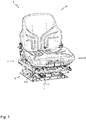
- FIG. 1 shows a vehicle seat 2 comprising a backrest 25 and a seat part 24, wherein the seat part 24 is arranged on the vehicle seat upper part 4.
- the vehicle seat upper part 4 is connected to the vehicle seat lower part 3 via a scissor frame 6 which has a first rocker arm 31 and a second rocker arm 32.
- the vehicle seat bottom 3 is preferably fixedly connected to a body of the vehicle (not shown here).
- the measuring device 1 is arranged on the first shearing part 6 of the first rocker 31.
- FIGS. 2A and 2B show the measuring device 1 according to a particularly preferred embodiment in detail.
- the measuring device 1 comprises an angle sensor unit 11 which is connected to a lever device 12 by means of a third axis 21.
- the lever device 12 in this case comprises a first lever arm 13 and a second lever arm 14, wherein the first lever arm 13 in its first end pivotally connected to the vehicle seat bottom 3 (not shown here) by means of a connection 35, in particular a screw 35 and a plate 35 ', connectable is.
- a first end region of a second lever arm 14 is articulated by means of a second axis 20, wherein in a second end region 18 of the second lever arm 14, the second lever arm can be connected to the angle sensor unit 11 by means of a third axis 21.
- the second end portion 18 of the second lever arm 14 is formed as a clip-on connector 36, whereby a particularly simple assembly and disassembly is possible.
- the angle sensor unit 11 comprises two wings 38, each having a recess 39.
- a connecting element 40 of a holder plate 34 can be introduced, wherein the recess 39 is formed such that after introduction of the connecting element 40 into the recess 39, the connecting element 40 can be rotated in the recess 39 and so firmly connected to the recess 39 is. This also facilitates the assembly or disassembly of the measuring device.
- the angle sensor unit 11 can also be easily connected to the first shearing part 6 by means of the holder plate 34 as well.
- the holder plate 34 comprises a data interface 33, by means of which the measurement data of the angle sensor unit 11 can be transmitted to the control device 22 (not shown here).
- Conceivable data interfaces include a USB interface, a LAN connection or a Bluetooth connection.
- the holder plate 34 is already attached to the first shearing part 6, so that the angle sensor unit 11 can be easily mounted or dismounted on the first shearing part 6.
- the measuring device 1 can be seen in an installed state.
- the first scissor member 6 is not visible, but only one connected to the first scissor member 6 connecting plate 42 on which the holder plate 34 is mounted.
- the data in this embodiment, wired by means of a cable 41 of the measuring device 1, in particular the angle sensor unit 11, is weglitebar.
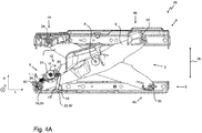
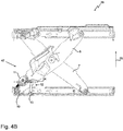
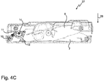
- the measuring device 1 is also schematically seen in an installed state. Shown in these figures, the entire seat base comprising the vehicle seat upper part 4, the vehicle seat lower part 3, the scissors frame 5 and the measuring device 1 with the angle sensor unit 11 and the lever device 12.
- the lever device is designed such that it can perform movements in the plane defined by the vehicle seat longitudinal direction L and vehicle seat height direction H level.
- the first 19, second 20 and third axis 21 are formed substantially perpendicular to this plane, so extend in the vehicle seat width direction B.
- the scissors-type frame 5 can be seen in a side view and comprises a first shearing part 6 and a second shaving part 7, wherein the first 6 and the second shearing part 7 are connected by means of a rotation axis.
- the first shearing part 6 is pivotally mounted in its first end region 9 by means of a pivot axis 10 on the vehicle seat bottom.
- the first shearing part 6 is thus advantageously secured by means of a fixed bearing 29 with the vehicle seat bottom part 3.
- FIG. 4A is also a first end portion 44 of the second shearing part 7 connected by means of a fixed bearing 29 with the vehicle seat upper part 4. Because of this arrangement, the fixed bearing 29, it is necessary that respective second end portions 45, 46 of the first 6 and second scissor member 7 are connected via a movable bearing with the vehicle seat bottom 3 and vehicle seat shell 4.
- the pivot axis 10 is in this case enclosed by an envelope 43, for example in the form of a tube.
- the holder plate 34 is connected to the envelope 43, advantageously via a welded connection. That is, when the vehicle seat upper 4 is deflected, the first shearing part 6 is pivoted about the pivot axis 10 and the holder plate is pivoted accordingly. This pivoting is made by comparing the Figures 4A-C clear.
- the angle sensor unit 11 On the holder plate 34, the angle sensor unit 11 is also arranged, which is also connected via a lever device 12 to the vehicle seat bottom part 3. The data recorded by the angle sensor unit 11 can be forwarded by means of the data interface 33 to a control device 22 (not shown here).
- the vehicle seat 2 for a height leveling unit (not shown here), which controls the vehicle seat so that the vehicle seat, when no forces act, is set in the zero position 25.
- a force 28 acts on the vehicle seat 2 in the vertical direction, that is, in the vehicle seat height direction H, then, depending on the direction of the force 28, the vehicle seat upper part 4 is deflected either downwards or upwards in the vehicle seat height direction H.
- a deflection of the vehicle seat upper part 4 in the vehicle longitudinal direction H upwards is in the FIG. 4B shown, a deflection of the vehicle seat upper part 4 down in the FIG. 4C ,
- the angle sensor unit 11 has been pivoted about the pivot axis 10 analogous to the first shearing part 6.
- the angle sensor unit 11 was operated by the lever device 12, as from a comparison of the lever device of FIG. 4A with the FIG. 4B evident.
- the second lever arm 14 of the lever device 12 extends in the FIG. 4A essentially in vehicle longitudinal direction L.
- the second lever arm 14 deviates from this orientation and now extends at an angle to the vehicle seat longitudinal direction L.
- the operation of the angle sensor unit 11 at a force 28 in the vehicle seat height direction H downwards, as shown in the FIG. 4C is pictured.
- the first shearing part 6 is hereby pivoted in the opposite direction.
- the second lever arm 14 is deflected in the opposite direction relative to the vehicle seat longitudinal direction.
- the control device determines whether it is a deflection in the vehicle seat height direction H upwards or downwards.
- it can be determined by means of the data recorded by the angle sensor unit, which deflection the vehicle seat upper part 4 experiences relative to the vehicle seat bottom part 3.
- these Values are also determined by the control device, how fast this deflection happens and what acceleration acts on the vehicle seat upper part 4.
- the deflection height, the deflection speed and the deflection acceleration can be determined.
- the spring and / or the damping properties of a spring and / or a damper can advantageously be changed by means of the control device in order to prevent a critical deflection up to the respective end stop and the driver so abrupt and unwanted stops the deflection movement can be prevented.
- the driver can continue to be taught a comfortable and safe driving experience.
Landscapes
- Engineering & Computer Science (AREA)
- Aviation & Aerospace Engineering (AREA)
- Transportation (AREA)
- Mechanical Engineering (AREA)
- Physics & Mathematics (AREA)
- General Physics & Mathematics (AREA)
- Seats For Vehicles (AREA)
Applications Claiming Priority (1)
| Application Number | Priority Date | Filing Date | Title |
|---|---|---|---|
| DE102015106360.3A DE102015106360B4 (de) | 2015-04-24 | 2015-04-24 | Messeinrichtung für einen Fahrzeugsitz |
Publications (2)
| Publication Number | Publication Date |
|---|---|
| EP3085579A1 true EP3085579A1 (fr) | 2016-10-26 |
| EP3085579B1 EP3085579B1 (fr) | 2018-11-14 |
Family
ID=55587129
Family Applications (1)
| Application Number | Title | Priority Date | Filing Date |
|---|---|---|---|
| EP16160864.1A Active EP3085579B1 (fr) | 2015-04-24 | 2016-03-17 | Mecanisme basculant a capteur angulaire |
Country Status (4)
| Country | Link |
|---|---|
| US (1) | US9970786B2 (fr) |
| EP (1) | EP3085579B1 (fr) |
| CN (1) | CN106064571B (fr) |
| DE (1) | DE102015106360B4 (fr) |
Cited By (2)
| Publication number | Priority date | Publication date | Assignee | Title |
|---|---|---|---|---|
| US11353084B2 (en) * | 2013-03-15 | 2022-06-07 | Clearmotion Acquisition I Llc | Rotary actuator driven vibration isolation |
| FR3132881A1 (fr) * | 2022-02-21 | 2023-08-25 | Faurecia Sièges d'Automobile | Siège de véhicule comprenant un dispositif de mesure de distance entre une base et une armature |
Families Citing this family (6)
| Publication number | Priority date | Publication date | Assignee | Title |
|---|---|---|---|---|
| DE102016124696B4 (de) * | 2016-12-16 | 2018-12-13 | Grammer Aktiengesellschaft | Fahrzeugkabine oder Fahrzeugsitz mit Höhenverstelleinrichtung |
| WO2018182998A1 (fr) * | 2017-03-31 | 2018-10-04 | Clearmotion Acquisition I Llc | Système de siège pour un véhicule |
| DE102020110757B3 (de) * | 2020-04-21 | 2021-09-16 | Grammer Aktiengesellschaft | Fahrzeugsitz |
| CN112729197B (zh) * | 2021-01-27 | 2025-01-28 | 长春光华荣昌汽车部件有限公司 | 一种座椅高度测量装置和座椅底座 |
| WO2023034439A1 (fr) * | 2021-09-01 | 2023-03-09 | Suspension Systems Technologies, Llc | Système de suspension |
| FR3134765A1 (fr) * | 2022-04-22 | 2023-10-27 | Faurecia Sièges d'Automobile | Siège de véhicule comprenant un dispositif de mesure déformable de distance entre une base et une armature |
Citations (5)
| Publication number | Priority date | Publication date | Assignee | Title |
|---|---|---|---|---|
| US5169112A (en) * | 1991-08-26 | 1992-12-08 | Milsco Manufacturing Company | Electronic suspension vehicle seat |
| DE4335199C1 (de) * | 1993-10-15 | 1995-05-11 | Grammer Ag | Abgefederter Fahrzeugsitz |
| EP1533176A2 (fr) * | 2003-11-22 | 2005-05-25 | Grammer Ag | Siège de véhicule à ajustement automatique en hauteur et procédé correspondant |
| DE102010026015A1 (de) * | 2010-07-01 | 2012-01-05 | Keiper Gmbh & Co. Kg | Fahrzeugsitz, insbesondere Nutzfahrzeugsitz |
| FR3007340A1 (fr) * | 2013-06-19 | 2014-12-26 | Peugeot Citroen Automobiles Sa | Siege pour vehicule a suspension reglable |
Family Cites Families (5)
| Publication number | Priority date | Publication date | Assignee | Title |
|---|---|---|---|---|
| US4022411A (en) * | 1975-06-27 | 1977-05-10 | Royal Industries, Inc. | Self-levelling seat suspension system for vehicles |
| US5964455A (en) * | 1997-06-13 | 1999-10-12 | Lord Corporation | Method for auto-calibration of a controllable damper suspension system |
| JP2001012998A (ja) * | 1999-05-20 | 2001-01-19 | Takata Corp | シート重量測定装置 |
| US7665585B2 (en) * | 2004-09-03 | 2010-02-23 | Alexandridis Alexander A | Vehicle suspension system and method for operating |
| DE102008020865B4 (de) * | 2008-04-25 | 2010-02-18 | Grammer Ag | Fahrzeugsitz mit einer Einrichtung für eine Fahrzeugsitzbelegungserkennung |
-
2015
- 2015-04-24 DE DE102015106360.3A patent/DE102015106360B4/de active Active
-
2016
- 2016-03-17 EP EP16160864.1A patent/EP3085579B1/fr active Active
- 2016-04-14 US US15/098,579 patent/US9970786B2/en active Active
- 2016-04-20 CN CN201610248699.2A patent/CN106064571B/zh active Active
Patent Citations (5)
| Publication number | Priority date | Publication date | Assignee | Title |
|---|---|---|---|---|
| US5169112A (en) * | 1991-08-26 | 1992-12-08 | Milsco Manufacturing Company | Electronic suspension vehicle seat |
| DE4335199C1 (de) * | 1993-10-15 | 1995-05-11 | Grammer Ag | Abgefederter Fahrzeugsitz |
| EP1533176A2 (fr) * | 2003-11-22 | 2005-05-25 | Grammer Ag | Siège de véhicule à ajustement automatique en hauteur et procédé correspondant |
| DE102010026015A1 (de) * | 2010-07-01 | 2012-01-05 | Keiper Gmbh & Co. Kg | Fahrzeugsitz, insbesondere Nutzfahrzeugsitz |
| FR3007340A1 (fr) * | 2013-06-19 | 2014-12-26 | Peugeot Citroen Automobiles Sa | Siege pour vehicule a suspension reglable |
Cited By (3)
| Publication number | Priority date | Publication date | Assignee | Title |
|---|---|---|---|---|
| US11353084B2 (en) * | 2013-03-15 | 2022-06-07 | Clearmotion Acquisition I Llc | Rotary actuator driven vibration isolation |
| FR3132881A1 (fr) * | 2022-02-21 | 2023-08-25 | Faurecia Sièges d'Automobile | Siège de véhicule comprenant un dispositif de mesure de distance entre une base et une armature |
| US12270642B2 (en) | 2022-02-21 | 2025-04-08 | Faurecia Sièges d'Automobile | Vehicle seat comprising a device for measuring the distance between a base and a frame |
Also Published As
| Publication number | Publication date |
|---|---|
| US20160313140A1 (en) | 2016-10-27 |
| CN106064571B (zh) | 2018-07-17 |
| DE102015106360B4 (de) | 2020-03-12 |
| DE102015106360A1 (de) | 2016-10-27 |
| CN106064571A (zh) | 2016-11-02 |
| EP3085579B1 (fr) | 2018-11-14 |
| US9970786B2 (en) | 2018-05-15 |
Similar Documents
| Publication | Publication Date | Title |
|---|---|---|
| EP3085579B1 (fr) | Mecanisme basculant a capteur angulaire | |
| EP3428009B1 (fr) | Siège de véhicule doté d'un amortisseur réglable | |
| EP3181396B1 (fr) | Dispositif de vibration de véhicule | |
| EP3013613B1 (fr) | Ressort a l'air avec dispositif de mesure de niveau intégré dans le soufflet | |
| DE102018126404B4 (de) | Fahrzeugsitz mit einer Restfederwegsteuerung | |
| DE102014117101B4 (de) | Armlehnenanordnung für einen Sitz, insbesondere für einen Fahrzeugsitz und Fahrzeugsitz | |
| DE2200848A1 (de) | Sicherheitseinrichtung fuer ein roentgenuntersuchungsgeraet mit einem schwenkbaren patientenlagerungstisch | |
| EP3178691B1 (fr) | Système de suspension | |
| DD281655A5 (de) | Verfahren und einrichtung zum feststellen und einstellen der lage von laufwerken | |
| DE4240790C1 (de) | Scharnier für eine hochschwenkbare Abdeckhaube eines Kraftwagens | |
| EP2683608A1 (fr) | Dispositif à aile battante et procédé permettant de faire fonctionner un dispositif à aile battante | |
| EP3263397A1 (fr) | Système de suspension | |
| EP3835123B1 (fr) | Siège de véhicule doté d'unité de ressort permettant de faire ressort du mouvement de ressort vertical et de roulis | |
| DE102015121765B4 (de) | Fahrzeugschwingungsvorrichtung | |
| EP3835121B1 (fr) | Siège de véhicule doté d'une unité de ressort permettant de faire ressort du mouvement de roulis et de ressort vertical | |
| DE19983462B3 (de) | Eine Lokalisierungsvorrichtung zur Bestimmung der örtlichen Lage eines Bauteils eines Fahrzeugs am Fahrzeugrahmen des Fahrzeugs | |
| WO2019076707A1 (fr) | Adaptateur de moissonneuse muni d'un palpeur de sol mécanique | |
| DE102024200286B4 (de) | Schwinggestell für einen fahrzeugsitz, insbesondere einen schwingsitz und/oder nutzfahrzeugsitz, und ein solcher fahrzeugsitz | |
| DE69501814T2 (de) | Apparat für den Ausgleich der Kräfte die auf einen, bei einer Last gezogenen, Arm wirken | |
| DE2224315A1 (de) | Achsanlenkung fuer kraftfahrzeuge mit luftfedern | |
| DE3151431C2 (fr) | ||
| DE3942252A1 (de) | Flugzeugsteuereinrichtung, insbesondere seitensteuerung | |
| DE3612203C2 (de) | Sitzanordnung in einem Bergungs- oder Bedienungsfahrzeug | |
| DE1683366B1 (de) | Raffbare Lamellenjalousie mit einer in der senkrechten Abschirmebene beweglichen Stelleiste | |
| DE102023103781A1 (de) | Fahrzeugsitz mit einer Vorrichtung zum Messen des Abstands zwischen einem Unterbau und einem Rahmen |
Legal Events
| Date | Code | Title | Description |
|---|---|---|---|
| PUAI | Public reference made under article 153(3) epc to a published international application that has entered the european phase |
Free format text: ORIGINAL CODE: 0009012 |
|
| AK | Designated contracting states |
Kind code of ref document: A1 Designated state(s): AL AT BE BG CH CY CZ DE DK EE ES FI FR GB GR HR HU IE IS IT LI LT LU LV MC MK MT NL NO PL PT RO RS SE SI SK SM TR |
|
| AX | Request for extension of the european patent |
Extension state: BA ME |
|
| STAA | Information on the status of an ep patent application or granted ep patent |
Free format text: STATUS: REQUEST FOR EXAMINATION WAS MADE |
|
| 17P | Request for examination filed |
Effective date: 20161109 |
|
| RBV | Designated contracting states (corrected) |
Designated state(s): AL AT BE BG CH CY CZ DE DK EE ES FI FR GB GR HR HU IE IS IT LI LT LU LV MC MK MT NL NO PL PT RO RS SE SI SK SM TR |
|
| GRAP | Despatch of communication of intention to grant a patent |
Free format text: ORIGINAL CODE: EPIDOSNIGR1 |
|
| STAA | Information on the status of an ep patent application or granted ep patent |
Free format text: STATUS: GRANT OF PATENT IS INTENDED |
|
| RIC1 | Information provided on ipc code assigned before grant |
Ipc: G01D 5/14 20060101ALI20180528BHEP Ipc: B60N 2/50 20060101AFI20180528BHEP Ipc: B60N 2/02 20060101ALI20180528BHEP Ipc: B60N 2/16 20060101ALI20180528BHEP |
|
| INTG | Intention to grant announced |
Effective date: 20180629 |
|
| GRAS | Grant fee paid |
Free format text: ORIGINAL CODE: EPIDOSNIGR3 |
|
| GRAA | (expected) grant |
Free format text: ORIGINAL CODE: 0009210 |
|
| STAA | Information on the status of an ep patent application or granted ep patent |
Free format text: STATUS: THE PATENT HAS BEEN GRANTED |
|
| AK | Designated contracting states |
Kind code of ref document: B1 Designated state(s): AL AT BE BG CH CY CZ DE DK EE ES FI FR GB GR HR HU IE IS IT LI LT LU LV MC MK MT NL NO PL PT RO RS SE SI SK SM TR |
|
| REG | Reference to a national code |
Ref country code: CH Ref legal event code: EP Ref country code: AT Ref legal event code: REF Ref document number: 1064402 Country of ref document: AT Kind code of ref document: T Effective date: 20181115 |
|
| REG | Reference to a national code |
Ref country code: DE Ref legal event code: R096 Ref document number: 502016002467 Country of ref document: DE |
|
| REG | Reference to a national code |
Ref country code: IE Ref legal event code: FG4D Free format text: LANGUAGE OF EP DOCUMENT: GERMAN |
|
| REG | Reference to a national code |
Ref country code: NL Ref legal event code: MP Effective date: 20181114 |
|
| REG | Reference to a national code |
Ref country code: LT Ref legal event code: MG4D |
|
| PG25 | Lapsed in a contracting state [announced via postgrant information from national office to epo] |
Ref country code: LV Free format text: LAPSE BECAUSE OF FAILURE TO SUBMIT A TRANSLATION OF THE DESCRIPTION OR TO PAY THE FEE WITHIN THE PRESCRIBED TIME-LIMIT Effective date: 20181114 Ref country code: ES Free format text: LAPSE BECAUSE OF FAILURE TO SUBMIT A TRANSLATION OF THE DESCRIPTION OR TO PAY THE FEE WITHIN THE PRESCRIBED TIME-LIMIT Effective date: 20181114 Ref country code: LT Free format text: LAPSE BECAUSE OF FAILURE TO SUBMIT A TRANSLATION OF THE DESCRIPTION OR TO PAY THE FEE WITHIN THE PRESCRIBED TIME-LIMIT Effective date: 20181114 Ref country code: NO Free format text: LAPSE BECAUSE OF FAILURE TO SUBMIT A TRANSLATION OF THE DESCRIPTION OR TO PAY THE FEE WITHIN THE PRESCRIBED TIME-LIMIT Effective date: 20190214 Ref country code: FI Free format text: LAPSE BECAUSE OF FAILURE TO SUBMIT A TRANSLATION OF THE DESCRIPTION OR TO PAY THE FEE WITHIN THE PRESCRIBED TIME-LIMIT Effective date: 20181114 Ref country code: IS Free format text: LAPSE BECAUSE OF FAILURE TO SUBMIT A TRANSLATION OF THE DESCRIPTION OR TO PAY THE FEE WITHIN THE PRESCRIBED TIME-LIMIT Effective date: 20190314 Ref country code: BG Free format text: LAPSE BECAUSE OF FAILURE TO SUBMIT A TRANSLATION OF THE DESCRIPTION OR TO PAY THE FEE WITHIN THE PRESCRIBED TIME-LIMIT Effective date: 20190214 Ref country code: HR Free format text: LAPSE BECAUSE OF FAILURE TO SUBMIT A TRANSLATION OF THE DESCRIPTION OR TO PAY THE FEE WITHIN THE PRESCRIBED TIME-LIMIT Effective date: 20181114 |
|
| PG25 | Lapsed in a contracting state [announced via postgrant information from national office to epo] |
Ref country code: GR Free format text: LAPSE BECAUSE OF FAILURE TO SUBMIT A TRANSLATION OF THE DESCRIPTION OR TO PAY THE FEE WITHIN THE PRESCRIBED TIME-LIMIT Effective date: 20190215 Ref country code: NL Free format text: LAPSE BECAUSE OF FAILURE TO SUBMIT A TRANSLATION OF THE DESCRIPTION OR TO PAY THE FEE WITHIN THE PRESCRIBED TIME-LIMIT Effective date: 20181114 Ref country code: SE Free format text: LAPSE BECAUSE OF FAILURE TO SUBMIT A TRANSLATION OF THE DESCRIPTION OR TO PAY THE FEE WITHIN THE PRESCRIBED TIME-LIMIT Effective date: 20181114 Ref country code: PT Free format text: LAPSE BECAUSE OF FAILURE TO SUBMIT A TRANSLATION OF THE DESCRIPTION OR TO PAY THE FEE WITHIN THE PRESCRIBED TIME-LIMIT Effective date: 20190314 Ref country code: AL Free format text: LAPSE BECAUSE OF FAILURE TO SUBMIT A TRANSLATION OF THE DESCRIPTION OR TO PAY THE FEE WITHIN THE PRESCRIBED TIME-LIMIT Effective date: 20181114 Ref country code: RS Free format text: LAPSE BECAUSE OF FAILURE TO SUBMIT A TRANSLATION OF THE DESCRIPTION OR TO PAY THE FEE WITHIN THE PRESCRIBED TIME-LIMIT Effective date: 20181114 |
|
| PG25 | Lapsed in a contracting state [announced via postgrant information from national office to epo] |
Ref country code: DK Free format text: LAPSE BECAUSE OF FAILURE TO SUBMIT A TRANSLATION OF THE DESCRIPTION OR TO PAY THE FEE WITHIN THE PRESCRIBED TIME-LIMIT Effective date: 20181114 Ref country code: PL Free format text: LAPSE BECAUSE OF FAILURE TO SUBMIT A TRANSLATION OF THE DESCRIPTION OR TO PAY THE FEE WITHIN THE PRESCRIBED TIME-LIMIT Effective date: 20181114 Ref country code: CZ Free format text: LAPSE BECAUSE OF FAILURE TO SUBMIT A TRANSLATION OF THE DESCRIPTION OR TO PAY THE FEE WITHIN THE PRESCRIBED TIME-LIMIT Effective date: 20181114 |
|
| REG | Reference to a national code |
Ref country code: DE Ref legal event code: R097 Ref document number: 502016002467 Country of ref document: DE |
|
| PG25 | Lapsed in a contracting state [announced via postgrant information from national office to epo] |
Ref country code: RO Free format text: LAPSE BECAUSE OF FAILURE TO SUBMIT A TRANSLATION OF THE DESCRIPTION OR TO PAY THE FEE WITHIN THE PRESCRIBED TIME-LIMIT Effective date: 20181114 Ref country code: SM Free format text: LAPSE BECAUSE OF FAILURE TO SUBMIT A TRANSLATION OF THE DESCRIPTION OR TO PAY THE FEE WITHIN THE PRESCRIBED TIME-LIMIT Effective date: 20181114 Ref country code: EE Free format text: LAPSE BECAUSE OF FAILURE TO SUBMIT A TRANSLATION OF THE DESCRIPTION OR TO PAY THE FEE WITHIN THE PRESCRIBED TIME-LIMIT Effective date: 20181114 Ref country code: SK Free format text: LAPSE BECAUSE OF FAILURE TO SUBMIT A TRANSLATION OF THE DESCRIPTION OR TO PAY THE FEE WITHIN THE PRESCRIBED TIME-LIMIT Effective date: 20181114 |
|
| PLBE | No opposition filed within time limit |
Free format text: ORIGINAL CODE: 0009261 |
|
| STAA | Information on the status of an ep patent application or granted ep patent |
Free format text: STATUS: NO OPPOSITION FILED WITHIN TIME LIMIT |
|
| 26N | No opposition filed |
Effective date: 20190815 |
|
| PG25 | Lapsed in a contracting state [announced via postgrant information from national office to epo] |
Ref country code: MC Free format text: LAPSE BECAUSE OF FAILURE TO SUBMIT A TRANSLATION OF THE DESCRIPTION OR TO PAY THE FEE WITHIN THE PRESCRIBED TIME-LIMIT Effective date: 20181114 Ref country code: SI Free format text: LAPSE BECAUSE OF FAILURE TO SUBMIT A TRANSLATION OF THE DESCRIPTION OR TO PAY THE FEE WITHIN THE PRESCRIBED TIME-LIMIT Effective date: 20181114 |
|
| REG | Reference to a national code |
Ref country code: CH Ref legal event code: PL |
|
| PG25 | Lapsed in a contracting state [announced via postgrant information from national office to epo] |
Ref country code: LU Free format text: LAPSE BECAUSE OF NON-PAYMENT OF DUE FEES Effective date: 20190317 |
|
| REG | Reference to a national code |
Ref country code: BE Ref legal event code: MM Effective date: 20190331 |
|
| PG25 | Lapsed in a contracting state [announced via postgrant information from national office to epo] |
Ref country code: CH Free format text: LAPSE BECAUSE OF NON-PAYMENT OF DUE FEES Effective date: 20190331 Ref country code: IE Free format text: LAPSE BECAUSE OF NON-PAYMENT OF DUE FEES Effective date: 20190317 Ref country code: LI Free format text: LAPSE BECAUSE OF NON-PAYMENT OF DUE FEES Effective date: 20190331 |
|
| PG25 | Lapsed in a contracting state [announced via postgrant information from national office to epo] |
Ref country code: BE Free format text: LAPSE BECAUSE OF NON-PAYMENT OF DUE FEES Effective date: 20190331 |
|
| PG25 | Lapsed in a contracting state [announced via postgrant information from national office to epo] |
Ref country code: TR Free format text: LAPSE BECAUSE OF FAILURE TO SUBMIT A TRANSLATION OF THE DESCRIPTION OR TO PAY THE FEE WITHIN THE PRESCRIBED TIME-LIMIT Effective date: 20181114 |
|
| PG25 | Lapsed in a contracting state [announced via postgrant information from national office to epo] |
Ref country code: MT Free format text: LAPSE BECAUSE OF FAILURE TO SUBMIT A TRANSLATION OF THE DESCRIPTION OR TO PAY THE FEE WITHIN THE PRESCRIBED TIME-LIMIT Effective date: 20181114 |
|
| GBPC | Gb: european patent ceased through non-payment of renewal fee |
Effective date: 20200317 |
|
| PG25 | Lapsed in a contracting state [announced via postgrant information from national office to epo] |
Ref country code: GB Free format text: LAPSE BECAUSE OF NON-PAYMENT OF DUE FEES Effective date: 20200317 |
|
| PG25 | Lapsed in a contracting state [announced via postgrant information from national office to epo] |
Ref country code: CY Free format text: LAPSE BECAUSE OF FAILURE TO SUBMIT A TRANSLATION OF THE DESCRIPTION OR TO PAY THE FEE WITHIN THE PRESCRIBED TIME-LIMIT Effective date: 20181114 |
|
| PG25 | Lapsed in a contracting state [announced via postgrant information from national office to epo] |
Ref country code: HU Free format text: LAPSE BECAUSE OF FAILURE TO SUBMIT A TRANSLATION OF THE DESCRIPTION OR TO PAY THE FEE WITHIN THE PRESCRIBED TIME-LIMIT; INVALID AB INITIO Effective date: 20160317 |
|
| REG | Reference to a national code |
Ref country code: AT Ref legal event code: MM01 Ref document number: 1064402 Country of ref document: AT Kind code of ref document: T Effective date: 20210317 |
|
| PG25 | Lapsed in a contracting state [announced via postgrant information from national office to epo] |
Ref country code: MK Free format text: LAPSE BECAUSE OF FAILURE TO SUBMIT A TRANSLATION OF THE DESCRIPTION OR TO PAY THE FEE WITHIN THE PRESCRIBED TIME-LIMIT Effective date: 20181114 |
|
| PG25 | Lapsed in a contracting state [announced via postgrant information from national office to epo] |
Ref country code: AT Free format text: LAPSE BECAUSE OF NON-PAYMENT OF DUE FEES Effective date: 20210317 |
|
| P01 | Opt-out of the competence of the unified patent court (upc) registered |
Effective date: 20230522 |
|
| PGFP | Annual fee paid to national office [announced via postgrant information from national office to epo] |
Ref country code: IT Payment date: 20250331 Year of fee payment: 10 |
|
| PGFP | Annual fee paid to national office [announced via postgrant information from national office to epo] |
Ref country code: DE Payment date: 20260320 Year of fee payment: 11 |
|
| PGFP | Annual fee paid to national office [announced via postgrant information from national office to epo] |
Ref country code: FR Payment date: 20260325 Year of fee payment: 11 |