EP3085647B1 - Disque d'aspiration - Google Patents
Disque d'aspiration Download PDFInfo
- Publication number
- EP3085647B1 EP3085647B1 EP14861808.5A EP14861808A EP3085647B1 EP 3085647 B1 EP3085647 B1 EP 3085647B1 EP 14861808 A EP14861808 A EP 14861808A EP 3085647 B1 EP3085647 B1 EP 3085647B1
- Authority
- EP
- European Patent Office
- Prior art keywords
- sucking disc
- work piece
- separator plate
- end surface
- pads
- Prior art date
- Legal status (The legal status is an assumption and is not a legal conclusion. Google has not performed a legal analysis and makes no representation as to the accuracy of the status listed.)
- Not-in-force
Links
Images

Classifications
-
- B—PERFORMING OPERATIONS; TRANSPORTING
- B25—HAND TOOLS; PORTABLE POWER-DRIVEN TOOLS; MANIPULATORS
- B25J—MANIPULATORS; CHAMBERS PROVIDED WITH MANIPULATION DEVICES
- B25J15/00—Gripping heads and other end effectors
- B25J15/06—Gripping heads and other end effectors with vacuum or magnetic holding means
- B25J15/0616—Gripping heads and other end effectors with vacuum or magnetic holding means with vacuum
-
- B—PERFORMING OPERATIONS; TRANSPORTING
- B65—CONVEYING; PACKING; STORING; HANDLING THIN OR FILAMENTARY MATERIAL
- B65G—TRANSPORT OR STORAGE DEVICES, e.g. CONVEYORS FOR LOADING OR TIPPING, SHOP CONVEYOR SYSTEMS OR PNEUMATIC TUBE CONVEYORS
- B65G47/00—Article or material-handling devices associated with conveyors; Methods employing such devices
- B65G47/74—Feeding, transfer, or discharging devices of particular kinds or types
- B65G47/90—Devices for picking-up and depositing articles or materials
- B65G47/91—Devices for picking-up and depositing articles or materials incorporating pneumatic, e.g. suction, grippers
- B65G47/911—Devices for picking-up and depositing articles or materials incorporating pneumatic, e.g. suction, grippers with air blasts producing partial vacuum
Definitions
- the present invention relates to a sucking disc.
- a sucking disc for sucking a work piece including a sucking disc body defining a chamber with a circular cross section inside the sucking disc body; the chamber having a closed end surface and an opening end surface, the opening end surface formed to be an end surface for absorbing an object, and tangential nozzles disposed on a wall surface of the chamber.
- sucking disc of such generic type is disclosed in document CN 3640313 S .
- a mechanical clip tool typically has two or more splints which are capable of being opened and closed, so as to carry out a squeeze operation by forcedly squeezing the splints.
- the mechanical clip tool fails to pick up a soft sheet-shaped work piece (such as a slice of bread, a tomato slice or the like), and because there exists wear-out between various mechanical parts, the work load of routine maintenance is heavy.
- a rubber vacuum sucking disc has such advantages as simple structure and easy to repair and maintain, which is a pickup tool commonly used in a line of food production.
- To create a negative pressure in the inner chamber of the sucking disc by pumping the air out using a vacuum pump or a vacuum generator is the most common means.
- a quantity of air is sucked in due to the pressure difference when there is even a small gap around the edge of the sucking disc, and thus the suction force is greatly reduced.
- the problem is more serious especially if the work piece with a rough surface is absorbed, because the rubber sucking disc cannot fully fit into the surface of the work piece.
- a contaminant such as the residue or liquid may be sucked into the vacuum pipe of the sucking disc to result in a blockage.
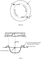
- CN 3640313 S discloses a sucking disc (as shown in FIG. 2a and FIG. 2b ), wherein two tangential nozzles are disposed on the wall surface of the cylindrical cavity of the sucking disc, fluids are injected from the nozzles and flow along the surface wall of the cylindrical cavity so as to form a swirling flow, due to the centrifugal force of the swirling flow, a low pressure distribution inside the cavity is formed which is lower than the external pressure around the sucking disc, thus enabling a plate-like work piece under the sucking disc to be sucked and held.
- the technology has the following defects:
- U. S. Patent 6,435,200 discloses a process for liquid treatment of a defined area of a wafer-shaped article, especially of a wafer, near the edge, in which the liquid is applied to a first surface, flows essentially radially to the outside to the peripheral-side edge of the wafer-shaped article and around this edge onto the second surface, the liquid wetting a defined section near the edge on the second surface and thereupon being removed from the wafer-shaped article. Furthermore the invention relates to a device for executing this process.
- Document DE 10 2011 111 768 A1 discloses a gripper having an air connection unit for supplying compressed air, which is connected to the gripping surface through pressure line such that compressed air is accelerated. The compressed air escapes into the environment, if the cross element rests against the gripping surface.
- the gripping surface is formed by an air-permeable, flexible gripping plate which is fixed to base portion in connecting region. A narrow gap formed between gripping plate and base portion, is connected to the pressure line, so that negative pressure is formed in the gap.
- U. S. Patent 8,196,983 discloses a substrate attracting device including an attracting body for attracting and holding a substrate to transfer the substrate.
- the attracting body includes a first attracting unit for attracting and holding a top surface of the substrate according to the Bernoulli principle and a second attracting unit for vacuum-attracting and holding a bottom surface of the substrate.
- Document US 2013/0234194 A1 discloses a light-emitting diode (LED) wafer picker that increases a suction force and performs stable adsorption without a concern for contact with a top surface of an LED.
- the wafer picker includes a main body to hold, in an adsorbed state, an LED wafer disposed below the main body, when air drawn in from a top of the LED wafer picker is discharged along a streamlined discharge surface to both sides of the LED wafer picker, a guide member to enable the air to flow along the discharge surface, the guide member being disposed below the discharge surface, a single central hole formed in a central portion of the guide member, excluding a portion facing the discharge surface, and a support portion to support the LED wafer, the support portion extending downward from the guide member.
- the present invention provides a sucking disc, in which the roughness or softness of the surface of a work piece has less influence on the suction force.
- a sucking disc for sucking a work piece including a sucking disc body defining a chamber with a circular cross section inside the sucking disc body; the chamber having a closed end surface and an opening end surface, the opening end surface formed to be an end surface for absorbing an object and tangential nozzles disposed on a wall surface of the chamber, wherein: the sucking disc further includes an annular separator plate and pads disposed apart from each other on the periphery of the opening end surface of the sucking disc body and an upper surface of the annular separator plate for fixedly attaching the annular separator plate to the periphery of the opening end surface of the sucking disc body via the pads; a partial area of the annular separator plate being covered by the pads, and a fixed channel from the annular separator plate to the periphery of the opening end surface of the sucking disc body formed by separations between the pads; the chamber being in communication with the ambient via the fixed channel, and a lower surface of the annular separator plate
- the pads are disposed and spaced at equal intervals on the periphery of the bottom surface of the sucking disc body.
- an annular separator plate is disposed under the sucking disc body and the pads are disposed between the annular separator plate and the sucking disc body, such that a fixed channel is formed between the periphery of the bottom surface of the sucking disc body and the annular separator plate, and the interior of the chamber of the sucking disc is in communication with the ambient.
- the fluids cannot flow into the gap between the work piece and the annual separator plate, such that the lower end surface of the annular separator plate is brought into full contact with the work piece, thus enabling enough friction to be formed in the horizontal direction to ensure that the work piece cannot slip down during the transportation of the work piece in the horizontal direction.
- a soft material such as rubber is attached to the lower end surface of the annular separator plate to obtain better friction effect.
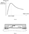
- the design of the height of the pads namely, the height of the fixed channel is very important. It is found by analysis of experiments that, if the height of the pads is too small, very high pressure distribution is formed under the effect of viscous friction during the time that the fluids flow through the narrow fixed channel, and the lower pressure distribution inside the chamber may be shifted toward higher pressure distribution due to the very high pressure distribution, thereby making the suction force weaken; if the height of the pads is progressively increased, the effect of the viscous friction in the fixed channel is weaken, such that the high pressure distribution in the fixed channel can be reduced and the lower pressure distribution inside the chamber can be shifted downward, thereby increasing the suction force; however, if the height of the pads continue to be increased, it is found that the suction force will be weaken instead.
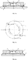
- a sucking disc includes a sucking disc body 1; there is a chamber 12 with a circular cross section inside the sucking disc body 1, and the chamber 12 has a closed end surface and an opening end surface, the opening end surface is formed to be an end surface for absorbing an object and tangential nozzles 11 are disposed on the wall surface of the chamber 12.
- the sucking disc further includes an annular separator plate 3 and pads 2; the pads 2 are disposed apart from each other on the periphery of the bottom surface of the sucking disc body 1 and the upper surface of the annular separator plate 3 is fixedly attached with the periphery of the bottom surface of the sucking disc body 1 via the pads 2; a partial area of the annular separator plate 3 is covered by the pads 2, a fixed channel from the annular separator plate 3 to the periphery of the bottom surface of the sucking disc body 1 is formed by the separations between the pads; and the interior of the chamber 12 is communicated with the ambient via the fixed channel.
- the pads 2 are disposed and spaced at equal intervals on the periphery of the bottom surface of the sucking disc body 1. In this embodiment, 4 pads are used.
- an annular separator plate is disposed under the sucking disc body and the pads are disposed between the annular separator plate and the sucking disc body, such that a fixed channel is formed between the periphery of the bottom surface of the sucking disc body and the annular separator plate, and the interior of the chamber of the sucking disc is in communication with the ambient.
- the fluids cannot flow into the gap between the work piece and the annual separator plate, such that the lower end surface of the annular separator plate is brought into full contact with the work piece, thus enabling enough friction to be formed in the horizontal direction to ensure that the work piece cannot slip down during the transportation of the work piece in the horizontal direction.
- a soft material such as rubber is attached to the lower end surface of the annular separator plate to obtain better friction effect.
Landscapes
- Engineering & Computer Science (AREA)
- Mechanical Engineering (AREA)
- Robotics (AREA)
- Manipulator (AREA)
- Hooks, Suction Cups, And Attachment By Adhesive Means (AREA)
Claims (4)
- Disque de succion destiné à aspirer une pièce usinée (4), comprenant un corps de disque de succion (1) définissant une chambre (12) avec une section transversale circulaire à l'intérieur du corps de disque de succion ; la chambre présentant une surface d'extrémité fermée et une surface d'extrémité ouverte, la surface d'extrémité ouverte étant formée pour être une surface d'extrémité destinée à absorber un objet, et des buses tangentielles (11) disposées sur une surface de paroi de la chambre, caractérisé en ce que le disque de succion comprend en outre une plaque séparatrice annulaire (3) et des coussinets (2) espacés les uns des autres sur une périphérie de la surface d'extrémité ouverte du corps de disque de succion et une surface supérieure de la plaque séparatrice annulaire, pour fixer solidement la plaque séparatrice annulaire à la périphérie de la surface d'extrémité ouverte du corps de disque de succion par le biais des coussinets ; une région partielle de la plaque séparatrice annulaire étant recouverte par les coussinets, et un canal fixe allant de la plaque séparatrice annulaire à la périphérie de la surface d'extrémité ouverte du corps de disque de succion, formé par des séparations entre les coussinets ; la chambre étant en communication avec l'environnement par le biais du canal fixe ; et une surface inférieure de la plaque séparatrice annulaire étant destinée à être mise entièrement en contact avec la pièce usinée (4) pour permettre une friction générée entre la surface inférieure et la pièce usinée (4).
- Disque de succion selon la revendication 1, dans lequel : les coussinets sont disposés et espacés à des intervalles égaux sur la périphérie de la surface d'extrémité ouverte du corps de disque de succion.
- Disque de succion selon la revendication 1, dans lequel : un matériau souple est fixé à une surface inférieure de la plaque séparatrice annulaire pour obtenir l'effet de friction lorsque la pièce usinée (4) touche la surface inférieure.
- Disque de succion selon la revendication 3, dans lequel : le matériau souple est du caoutchouc.
Applications Claiming Priority (2)
| Application Number | Priority Date | Filing Date | Title |
|---|---|---|---|
| CN201310571285.XA CN104626174B (zh) | 2013-11-13 | 2013-11-13 | 吸盘 |
| PCT/CN2014/090796 WO2015070742A1 (fr) | 2013-11-13 | 2014-11-11 | Disque d'aspiration |
Publications (3)
| Publication Number | Publication Date |
|---|---|
| EP3085647A1 EP3085647A1 (fr) | 2016-10-26 |
| EP3085647A4 EP3085647A4 (fr) | 2017-10-25 |
| EP3085647B1 true EP3085647B1 (fr) | 2019-07-17 |
Family
ID=53056768
Family Applications (1)
| Application Number | Title | Priority Date | Filing Date |
|---|---|---|---|
| EP14861808.5A Not-in-force EP3085647B1 (fr) | 2013-11-13 | 2014-11-11 | Disque d'aspiration |
Country Status (5)
| Country | Link |
|---|---|
| US (1) | US20160288334A1 (fr) |
| EP (1) | EP3085647B1 (fr) |
| JP (1) | JP6123030B2 (fr) |
| CN (1) | CN104626174B (fr) |
| WO (1) | WO2015070742A1 (fr) |
Families Citing this family (10)
| Publication number | Priority date | Publication date | Assignee | Title |
|---|---|---|---|---|
| JP2805428B2 (ja) | 1993-02-10 | 1998-09-30 | 株式会社トヨックス | 凍結吸収体付き散水ノズル |
| JP6116629B2 (ja) * | 2015-08-11 | 2017-04-19 | 株式会社ハーモテック | 吸引装置 |
| JP6744630B2 (ja) * | 2016-12-16 | 2020-08-19 | 株式会社ハーモテック | 邪魔板 |
| JP6924488B2 (ja) * | 2018-04-12 | 2021-08-25 | 株式会社ハーモテック | 旋回流形成体 |
| KR200492057Y1 (ko) * | 2019-03-21 | 2020-07-29 | 최영진 | 싱크대 물막이 |
| CN112388660A (zh) * | 2019-08-19 | 2021-02-23 | 浙江大学 | 吸附器 |
| CN111997985B (zh) * | 2020-07-29 | 2022-02-15 | 杭州孚亚科技有限公司 | 双空间吸附器 |
| JP7614633B2 (ja) * | 2021-04-01 | 2025-01-16 | 株式会社ハーモテック | 搬送装置、排出整流カバーおよびスカート |
| CN112943753B (zh) * | 2021-04-09 | 2022-06-24 | 浙江大学 | 一种扩张辐射流动机构 |
| CN117733630B (zh) * | 2023-12-29 | 2025-04-25 | 宁波倍特瑞新能源科技有限公司 | 一种吸盘式锌块加工用自动上下料旋转机械手臂 |
Family Cites Families (16)
| Publication number | Priority date | Publication date | Assignee | Title |
|---|---|---|---|---|
| JPS5297376U (fr) * | 1976-01-19 | 1977-07-21 | ||
| US5067762A (en) * | 1985-06-18 | 1991-11-26 | Hiroshi Akashi | Non-contact conveying device |
| JPH04365579A (ja) * | 1991-06-14 | 1992-12-17 | Toshiba Corp | 吸着ノズル |
| US5882055A (en) * | 1996-02-12 | 1999-03-16 | Aetrium Incorporated | Probe for handling microchips |
| WO1997045862A1 (fr) * | 1996-05-31 | 1997-12-04 | Ipec Precision, Inc. | Support sans contact pour des articles en forme de plaquette |
| DE59900743D1 (de) * | 1999-04-28 | 2002-02-28 | Sez Semiconduct Equip Zubehoer | Vorrichtung und Verfahren zur Flüssigkeitsbehandlung von scheibenförmigen Gegenständen |
| US6402843B1 (en) * | 1999-12-07 | 2002-06-11 | Trusi Technologies, Llc | Non-contact workpiece holder |
| JP2007154933A (ja) * | 2005-12-01 | 2007-06-21 | Kenwood Corp | 吸盤 |
| CN3640313S (fr) * | 2006-07-14 | 2007-05-02 | ||
| JP4243766B2 (ja) * | 2006-10-02 | 2009-03-25 | Smc株式会社 | 非接触搬送装置 |
| JP4740414B2 (ja) * | 2007-04-24 | 2011-08-03 | 東京エレクトロン株式会社 | 基板搬送装置 |
| JP2010052051A (ja) * | 2008-08-26 | 2010-03-11 | Seiko Epson Corp | ベルヌーイチャックおよび吸引保持ハンド |
| CN201369321Y (zh) * | 2009-03-23 | 2009-12-23 | 浙江大学 | 一种旋涡式非接触硅片夹持装置 |
| JP2010253567A (ja) * | 2009-04-21 | 2010-11-11 | Seiko Epson Corp | 吸引保持ハンド、吸引保持方法、及び搬送装置 |
| DE102011111768A1 (de) * | 2011-08-24 | 2013-02-28 | Robert Bosch Gmbh | Bernoulli-Greifer mit vollflächiger Werkstückanlage |
| US8904629B2 (en) * | 2012-03-09 | 2014-12-09 | LG CNS Co. Ltd. | Light-emitting diode (LED) wafer picker |
-
2013
- 2013-11-13 CN CN201310571285.XA patent/CN104626174B/zh active Active
-
2014
- 2014-11-11 WO PCT/CN2014/090796 patent/WO2015070742A1/fr not_active Ceased
- 2014-11-11 JP JP2016528899A patent/JP6123030B2/ja active Active
- 2014-11-11 US US15/035,305 patent/US20160288334A1/en not_active Abandoned
- 2014-11-11 EP EP14861808.5A patent/EP3085647B1/fr not_active Not-in-force
Non-Patent Citations (1)
| Title |
|---|
| None * |
Also Published As
| Publication number | Publication date |
|---|---|
| JP6123030B2 (ja) | 2017-04-26 |
| CN104626174B (zh) | 2016-06-15 |
| JP2017502216A (ja) | 2017-01-19 |
| US20160288334A1 (en) | 2016-10-06 |
| CN104626174A (zh) | 2015-05-20 |
| EP3085647A1 (fr) | 2016-10-26 |
| EP3085647A4 (fr) | 2017-10-25 |
| WO2015070742A1 (fr) | 2015-05-21 |
Similar Documents
| Publication | Publication Date | Title |
|---|---|---|
| EP3085647B1 (fr) | Disque d'aspiration | |
| KR100859835B1 (ko) | 비접촉식 진공패드 | |
| US8904629B2 (en) | Light-emitting diode (LED) wafer picker | |
| EP2708479A2 (fr) | Dispositif de préhension | |
| EP3782776B1 (fr) | Dispositif d'aspiration | |
| CN207542224U (zh) | 晶圆固定装置 | |
| JP6184594B2 (ja) | 青果物把持具 | |
| CN100595903C (zh) | 非接触式硅片夹持装置 | |
| CN205723489U (zh) | 一种用于夹持晶圆的卡盘 | |
| CN104482028B (zh) | 一种万能真空负压吸盘 | |
| KR101273570B1 (ko) | Led 웨이퍼 피커 | |
| CN205011023U (zh) | 一种平板吸取装置 | |
| JP4982875B2 (ja) | シート状物品のための非接触パッド | |
| CN102543815B (zh) | 用于转移石墨舟上半导体晶粒的吸盘装置 | |
| JP5417467B2 (ja) | Ledウェハーピッカー | |
| JP2014176914A (ja) | 吸着パッド及び吸着装置 | |
| CN207402796U (zh) | 一种吸取装置的持压结构 | |
| CN218024166U (zh) | 真空吸具 | |
| CN218753558U (zh) | 一种伯努利吸盘 | |
| CN221916342U (zh) | 一种液晶面板用吸盘 | |
| CN222348161U (zh) | 一种基于伯努利吸盘的吸具 | |
| CN221401327U (zh) | 一种稳定吸附的伯努利吸盘 | |
| CN223822860U (zh) | 一种柔性补偿器和真空吸具装置 | |
| CN223652444U (zh) | 电池座限位吸嘴 | |
| CN209078772U (zh) | 一种适用于有孔刀片的吸附式通用型吸嘴机构 |
Legal Events
| Date | Code | Title | Description |
|---|---|---|---|
| PUAI | Public reference made under article 153(3) epc to a published international application that has entered the european phase |
Free format text: ORIGINAL CODE: 0009012 |
|
| 17P | Request for examination filed |
Effective date: 20160809 |
|
| AK | Designated contracting states |
Kind code of ref document: A1 Designated state(s): AL AT BE BG CH CY CZ DE DK EE ES FI FR GB GR HR HU IE IS IT LI LT LU LV MC MK MT NL NO PL PT RO RS SE SI SK SM TR |
|
| AX | Request for extension of the european patent |
Extension state: BA ME |
|
| DAX | Request for extension of the european patent (deleted) | ||
| RIN1 | Information on inventor provided before grant (corrected) |
Inventor name: LI, XIN |
|
| A4 | Supplementary search report drawn up and despatched |
Effective date: 20170927 |
|
| RIC1 | Information provided on ipc code assigned before grant |
Ipc: B65G 47/91 20060101AFI20170921BHEP Ipc: B25J 15/06 20060101ALI20170921BHEP |
|
| STAA | Information on the status of an ep patent application or granted ep patent |
Free format text: STATUS: EXAMINATION IS IN PROGRESS |
|
| 17Q | First examination report despatched |
Effective date: 20180718 |
|
| GRAP | Despatch of communication of intention to grant a patent |
Free format text: ORIGINAL CODE: EPIDOSNIGR1 |
|
| STAA | Information on the status of an ep patent application or granted ep patent |
Free format text: STATUS: GRANT OF PATENT IS INTENDED |
|
| INTG | Intention to grant announced |
Effective date: 20190131 |
|
| GRAS | Grant fee paid |
Free format text: ORIGINAL CODE: EPIDOSNIGR3 |
|
| GRAA | (expected) grant |
Free format text: ORIGINAL CODE: 0009210 |
|
| STAA | Information on the status of an ep patent application or granted ep patent |
Free format text: STATUS: THE PATENT HAS BEEN GRANTED |
|
| AK | Designated contracting states |
Kind code of ref document: B1 Designated state(s): AL AT BE BG CH CY CZ DE DK EE ES FI FR GB GR HR HU IE IS IT LI LT LU LV MC MK MT NL NO PL PT RO RS SE SI SK SM TR |
|
| REG | Reference to a national code |
Ref country code: GB Ref legal event code: FG4D |
|
| REG | Reference to a national code |
Ref country code: CH Ref legal event code: EP |
|
| REG | Reference to a national code |
Ref country code: IE Ref legal event code: FG4D |
|
| REG | Reference to a national code |
Ref country code: DE Ref legal event code: R096 Ref document number: 602014050268 Country of ref document: DE |
|
| REG | Reference to a national code |
Ref country code: AT Ref legal event code: REF Ref document number: 1155674 Country of ref document: AT Kind code of ref document: T Effective date: 20190815 |
|
| REG | Reference to a national code |
Ref country code: NL Ref legal event code: MP Effective date: 20190717 |
|
| REG | Reference to a national code |
Ref country code: LT Ref legal event code: MG4D |
|
| REG | Reference to a national code |
Ref country code: AT Ref legal event code: MK05 Ref document number: 1155674 Country of ref document: AT Kind code of ref document: T Effective date: 20190717 |
|
| PG25 | Lapsed in a contracting state [announced via postgrant information from national office to epo] |
Ref country code: FI Free format text: LAPSE BECAUSE OF FAILURE TO SUBMIT A TRANSLATION OF THE DESCRIPTION OR TO PAY THE FEE WITHIN THE PRESCRIBED TIME-LIMIT Effective date: 20190717 Ref country code: SE Free format text: LAPSE BECAUSE OF FAILURE TO SUBMIT A TRANSLATION OF THE DESCRIPTION OR TO PAY THE FEE WITHIN THE PRESCRIBED TIME-LIMIT Effective date: 20190717 Ref country code: PT Free format text: LAPSE BECAUSE OF FAILURE TO SUBMIT A TRANSLATION OF THE DESCRIPTION OR TO PAY THE FEE WITHIN THE PRESCRIBED TIME-LIMIT Effective date: 20191118 Ref country code: HR Free format text: LAPSE BECAUSE OF FAILURE TO SUBMIT A TRANSLATION OF THE DESCRIPTION OR TO PAY THE FEE WITHIN THE PRESCRIBED TIME-LIMIT Effective date: 20190717 Ref country code: NL Free format text: LAPSE BECAUSE OF FAILURE TO SUBMIT A TRANSLATION OF THE DESCRIPTION OR TO PAY THE FEE WITHIN THE PRESCRIBED TIME-LIMIT Effective date: 20190717 Ref country code: AT Free format text: LAPSE BECAUSE OF FAILURE TO SUBMIT A TRANSLATION OF THE DESCRIPTION OR TO PAY THE FEE WITHIN THE PRESCRIBED TIME-LIMIT Effective date: 20190717 Ref country code: LT Free format text: LAPSE BECAUSE OF FAILURE TO SUBMIT A TRANSLATION OF THE DESCRIPTION OR TO PAY THE FEE WITHIN THE PRESCRIBED TIME-LIMIT Effective date: 20190717 Ref country code: NO Free format text: LAPSE BECAUSE OF FAILURE TO SUBMIT A TRANSLATION OF THE DESCRIPTION OR TO PAY THE FEE WITHIN THE PRESCRIBED TIME-LIMIT Effective date: 20191017 Ref country code: BG Free format text: LAPSE BECAUSE OF FAILURE TO SUBMIT A TRANSLATION OF THE DESCRIPTION OR TO PAY THE FEE WITHIN THE PRESCRIBED TIME-LIMIT Effective date: 20191017 |
|
| PG25 | Lapsed in a contracting state [announced via postgrant information from national office to epo] |
Ref country code: AL Free format text: LAPSE BECAUSE OF FAILURE TO SUBMIT A TRANSLATION OF THE DESCRIPTION OR TO PAY THE FEE WITHIN THE PRESCRIBED TIME-LIMIT Effective date: 20190717 Ref country code: ES Free format text: LAPSE BECAUSE OF FAILURE TO SUBMIT A TRANSLATION OF THE DESCRIPTION OR TO PAY THE FEE WITHIN THE PRESCRIBED TIME-LIMIT Effective date: 20190717 Ref country code: RS Free format text: LAPSE BECAUSE OF FAILURE TO SUBMIT A TRANSLATION OF THE DESCRIPTION OR TO PAY THE FEE WITHIN THE PRESCRIBED TIME-LIMIT Effective date: 20190717 Ref country code: LV Free format text: LAPSE BECAUSE OF FAILURE TO SUBMIT A TRANSLATION OF THE DESCRIPTION OR TO PAY THE FEE WITHIN THE PRESCRIBED TIME-LIMIT Effective date: 20190717 Ref country code: GR Free format text: LAPSE BECAUSE OF FAILURE TO SUBMIT A TRANSLATION OF THE DESCRIPTION OR TO PAY THE FEE WITHIN THE PRESCRIBED TIME-LIMIT Effective date: 20191018 Ref country code: IS Free format text: LAPSE BECAUSE OF FAILURE TO SUBMIT A TRANSLATION OF THE DESCRIPTION OR TO PAY THE FEE WITHIN THE PRESCRIBED TIME-LIMIT Effective date: 20191117 |
|
| PG25 | Lapsed in a contracting state [announced via postgrant information from national office to epo] |
Ref country code: TR Free format text: LAPSE BECAUSE OF FAILURE TO SUBMIT A TRANSLATION OF THE DESCRIPTION OR TO PAY THE FEE WITHIN THE PRESCRIBED TIME-LIMIT Effective date: 20190717 |
|
| PG25 | Lapsed in a contracting state [announced via postgrant information from national office to epo] |
Ref country code: IT Free format text: LAPSE BECAUSE OF FAILURE TO SUBMIT A TRANSLATION OF THE DESCRIPTION OR TO PAY THE FEE WITHIN THE PRESCRIBED TIME-LIMIT Effective date: 20190717 Ref country code: RO Free format text: LAPSE BECAUSE OF FAILURE TO SUBMIT A TRANSLATION OF THE DESCRIPTION OR TO PAY THE FEE WITHIN THE PRESCRIBED TIME-LIMIT Effective date: 20190717 Ref country code: PL Free format text: LAPSE BECAUSE OF FAILURE TO SUBMIT A TRANSLATION OF THE DESCRIPTION OR TO PAY THE FEE WITHIN THE PRESCRIBED TIME-LIMIT Effective date: 20190717 Ref country code: EE Free format text: LAPSE BECAUSE OF FAILURE TO SUBMIT A TRANSLATION OF THE DESCRIPTION OR TO PAY THE FEE WITHIN THE PRESCRIBED TIME-LIMIT Effective date: 20190717 Ref country code: DK Free format text: LAPSE BECAUSE OF FAILURE TO SUBMIT A TRANSLATION OF THE DESCRIPTION OR TO PAY THE FEE WITHIN THE PRESCRIBED TIME-LIMIT Effective date: 20190717 |
|
| PG25 | Lapsed in a contracting state [announced via postgrant information from national office to epo] |
Ref country code: CZ Free format text: LAPSE BECAUSE OF FAILURE TO SUBMIT A TRANSLATION OF THE DESCRIPTION OR TO PAY THE FEE WITHIN THE PRESCRIBED TIME-LIMIT Effective date: 20190717 Ref country code: SK Free format text: LAPSE BECAUSE OF FAILURE TO SUBMIT A TRANSLATION OF THE DESCRIPTION OR TO PAY THE FEE WITHIN THE PRESCRIBED TIME-LIMIT Effective date: 20190717 Ref country code: IS Free format text: LAPSE BECAUSE OF FAILURE TO SUBMIT A TRANSLATION OF THE DESCRIPTION OR TO PAY THE FEE WITHIN THE PRESCRIBED TIME-LIMIT Effective date: 20200224 Ref country code: SM Free format text: LAPSE BECAUSE OF FAILURE TO SUBMIT A TRANSLATION OF THE DESCRIPTION OR TO PAY THE FEE WITHIN THE PRESCRIBED TIME-LIMIT Effective date: 20190717 |
|
| REG | Reference to a national code |
Ref country code: DE Ref legal event code: R097 Ref document number: 602014050268 Country of ref document: DE |
|
| REG | Reference to a national code |
Ref country code: CH Ref legal event code: PL |
|
| PLBE | No opposition filed within time limit |
Free format text: ORIGINAL CODE: 0009261 |
|
| STAA | Information on the status of an ep patent application or granted ep patent |
Free format text: STATUS: NO OPPOSITION FILED WITHIN TIME LIMIT |
|
| PG2D | Information on lapse in contracting state deleted |
Ref country code: IS |
|
| PG25 | Lapsed in a contracting state [announced via postgrant information from national office to epo] |
Ref country code: LI Free format text: LAPSE BECAUSE OF NON-PAYMENT OF DUE FEES Effective date: 20191130 Ref country code: MC Free format text: LAPSE BECAUSE OF FAILURE TO SUBMIT A TRANSLATION OF THE DESCRIPTION OR TO PAY THE FEE WITHIN THE PRESCRIBED TIME-LIMIT Effective date: 20190717 Ref country code: CH Free format text: LAPSE BECAUSE OF NON-PAYMENT OF DUE FEES Effective date: 20191130 Ref country code: LU Free format text: LAPSE BECAUSE OF NON-PAYMENT OF DUE FEES Effective date: 20191111 |
|
| 26N | No opposition filed |
Effective date: 20200603 |
|
| REG | Reference to a national code |
Ref country code: BE Ref legal event code: MM Effective date: 20191130 |
|
| PG25 | Lapsed in a contracting state [announced via postgrant information from national office to epo] |
Ref country code: SI Free format text: LAPSE BECAUSE OF FAILURE TO SUBMIT A TRANSLATION OF THE DESCRIPTION OR TO PAY THE FEE WITHIN THE PRESCRIBED TIME-LIMIT Effective date: 20190717 |
|
| GBPC | Gb: european patent ceased through non-payment of renewal fee |
Effective date: 20191111 |
|
| PG25 | Lapsed in a contracting state [announced via postgrant information from national office to epo] |
Ref country code: FR Free format text: LAPSE BECAUSE OF NON-PAYMENT OF DUE FEES Effective date: 20191130 Ref country code: GB Free format text: LAPSE BECAUSE OF NON-PAYMENT OF DUE FEES Effective date: 20191111 Ref country code: IE Free format text: LAPSE BECAUSE OF NON-PAYMENT OF DUE FEES Effective date: 20191111 |
|
| PG25 | Lapsed in a contracting state [announced via postgrant information from national office to epo] |
Ref country code: BE Free format text: LAPSE BECAUSE OF NON-PAYMENT OF DUE FEES Effective date: 20191130 |
|
| PG25 | Lapsed in a contracting state [announced via postgrant information from national office to epo] |
Ref country code: CY Free format text: LAPSE BECAUSE OF FAILURE TO SUBMIT A TRANSLATION OF THE DESCRIPTION OR TO PAY THE FEE WITHIN THE PRESCRIBED TIME-LIMIT Effective date: 20190717 |
|
| PG25 | Lapsed in a contracting state [announced via postgrant information from national office to epo] |
Ref country code: HU Free format text: LAPSE BECAUSE OF FAILURE TO SUBMIT A TRANSLATION OF THE DESCRIPTION OR TO PAY THE FEE WITHIN THE PRESCRIBED TIME-LIMIT; INVALID AB INITIO Effective date: 20141111 Ref country code: MT Free format text: LAPSE BECAUSE OF FAILURE TO SUBMIT A TRANSLATION OF THE DESCRIPTION OR TO PAY THE FEE WITHIN THE PRESCRIBED TIME-LIMIT Effective date: 20190717 |
|
| PG25 | Lapsed in a contracting state [announced via postgrant information from national office to epo] |
Ref country code: MK Free format text: LAPSE BECAUSE OF FAILURE TO SUBMIT A TRANSLATION OF THE DESCRIPTION OR TO PAY THE FEE WITHIN THE PRESCRIBED TIME-LIMIT Effective date: 20190717 |
|
| REG | Reference to a national code |
Ref country code: DE Ref legal event code: R082 Ref document number: 602014050268 Country of ref document: DE Representative=s name: SUN, YIMING, M.SC. DIPL. SC. POL. UNIV., DE |
|
| PGFP | Annual fee paid to national office [announced via postgrant information from national office to epo] |
Ref country code: DE Payment date: 20231129 Year of fee payment: 10 |
|
| REG | Reference to a national code |
Ref country code: DE Ref legal event code: R119 Ref document number: 602014050268 Country of ref document: DE |
|
| PG25 | Lapsed in a contracting state [announced via postgrant information from national office to epo] |
Ref country code: DE Free format text: LAPSE BECAUSE OF NON-PAYMENT OF DUE FEES Effective date: 20250603 |