EP3085808A1 - Dispositif de chauffage et mécanisme d'application de revêtement le comprenant - Google Patents
Dispositif de chauffage et mécanisme d'application de revêtement le comprenant Download PDFInfo
- Publication number
- EP3085808A1 EP3085808A1 EP13899655.8A EP13899655A EP3085808A1 EP 3085808 A1 EP3085808 A1 EP 3085808A1 EP 13899655 A EP13899655 A EP 13899655A EP 3085808 A1 EP3085808 A1 EP 3085808A1
- Authority
- EP
- European Patent Office
- Prior art keywords
- coating material
- coating
- phase
- nozzle
- heating apparatus
- Prior art date
- Legal status (The legal status is an assumption and is not a legal conclusion. Google has not performed a legal analysis and makes no representation as to the accuracy of the status listed.)
- Granted
Links
Images






Classifications
-
- C—CHEMISTRY; METALLURGY
- C23—COATING METALLIC MATERIAL; COATING MATERIAL WITH METALLIC MATERIAL; CHEMICAL SURFACE TREATMENT; DIFFUSION TREATMENT OF METALLIC MATERIAL; COATING BY VACUUM EVAPORATION, BY SPUTTERING, BY ION IMPLANTATION OR BY CHEMICAL VAPOUR DEPOSITION, IN GENERAL; INHIBITING CORROSION OF METALLIC MATERIAL OR INCRUSTATION IN GENERAL
- C23C—COATING METALLIC MATERIAL; COATING MATERIAL WITH METALLIC MATERIAL; SURFACE TREATMENT OF METALLIC MATERIAL BY DIFFUSION INTO THE SURFACE, BY CHEMICAL CONVERSION OR SUBSTITUTION; COATING BY VACUUM EVAPORATION, BY SPUTTERING, BY ION IMPLANTATION OR BY CHEMICAL VAPOUR DEPOSITION, IN GENERAL
- C23C14/00—Coating by vacuum evaporation, by sputtering or by ion implantation of the coating forming material
- C23C14/22—Coating by vacuum evaporation, by sputtering or by ion implantation of the coating forming material characterised by the process of coating
- C23C14/24—Vacuum evaporation
- C23C14/26—Vacuum evaporation by resistance or inductive heating of the source
-
- C—CHEMISTRY; METALLURGY
- C23—COATING METALLIC MATERIAL; COATING MATERIAL WITH METALLIC MATERIAL; CHEMICAL SURFACE TREATMENT; DIFFUSION TREATMENT OF METALLIC MATERIAL; COATING BY VACUUM EVAPORATION, BY SPUTTERING, BY ION IMPLANTATION OR BY CHEMICAL VAPOUR DEPOSITION, IN GENERAL; INHIBITING CORROSION OF METALLIC MATERIAL OR INCRUSTATION IN GENERAL
- C23C—COATING METALLIC MATERIAL; COATING MATERIAL WITH METALLIC MATERIAL; SURFACE TREATMENT OF METALLIC MATERIAL BY DIFFUSION INTO THE SURFACE, BY CHEMICAL CONVERSION OR SUBSTITUTION; COATING BY VACUUM EVAPORATION, BY SPUTTERING, BY ION IMPLANTATION OR BY CHEMICAL VAPOUR DEPOSITION, IN GENERAL
- C23C14/00—Coating by vacuum evaporation, by sputtering or by ion implantation of the coating forming material
- C23C14/22—Coating by vacuum evaporation, by sputtering or by ion implantation of the coating forming material characterised by the process of coating
- C23C14/24—Vacuum evaporation
-
- C—CHEMISTRY; METALLURGY
- C23—COATING METALLIC MATERIAL; COATING MATERIAL WITH METALLIC MATERIAL; CHEMICAL SURFACE TREATMENT; DIFFUSION TREATMENT OF METALLIC MATERIAL; COATING BY VACUUM EVAPORATION, BY SPUTTERING, BY ION IMPLANTATION OR BY CHEMICAL VAPOUR DEPOSITION, IN GENERAL; INHIBITING CORROSION OF METALLIC MATERIAL OR INCRUSTATION IN GENERAL
- C23C—COATING METALLIC MATERIAL; COATING MATERIAL WITH METALLIC MATERIAL; SURFACE TREATMENT OF METALLIC MATERIAL BY DIFFUSION INTO THE SURFACE, BY CHEMICAL CONVERSION OR SUBSTITUTION; COATING BY VACUUM EVAPORATION, BY SPUTTERING, BY ION IMPLANTATION OR BY CHEMICAL VAPOUR DEPOSITION, IN GENERAL
- C23C14/00—Coating by vacuum evaporation, by sputtering or by ion implantation of the coating forming material
- C23C14/06—Coating by vacuum evaporation, by sputtering or by ion implantation of the coating forming material characterised by the coating material
-
- C—CHEMISTRY; METALLURGY
- C23—COATING METALLIC MATERIAL; COATING MATERIAL WITH METALLIC MATERIAL; CHEMICAL SURFACE TREATMENT; DIFFUSION TREATMENT OF METALLIC MATERIAL; COATING BY VACUUM EVAPORATION, BY SPUTTERING, BY ION IMPLANTATION OR BY CHEMICAL VAPOUR DEPOSITION, IN GENERAL; INHIBITING CORROSION OF METALLIC MATERIAL OR INCRUSTATION IN GENERAL
- C23C—COATING METALLIC MATERIAL; COATING MATERIAL WITH METALLIC MATERIAL; SURFACE TREATMENT OF METALLIC MATERIAL BY DIFFUSION INTO THE SURFACE, BY CHEMICAL CONVERSION OR SUBSTITUTION; COATING BY VACUUM EVAPORATION, BY SPUTTERING, BY ION IMPLANTATION OR BY CHEMICAL VAPOUR DEPOSITION, IN GENERAL
- C23C14/00—Coating by vacuum evaporation, by sputtering or by ion implantation of the coating forming material
- C23C14/22—Coating by vacuum evaporation, by sputtering or by ion implantation of the coating forming material characterised by the process of coating
- C23C14/24—Vacuum evaporation
- C23C14/246—Replenishment of source material
Definitions
- the present disclosure relates to a heating apparatus configured to generate coating vapor (gas) to coat a continuously moving base metal (steel sheet) with the coating vapor by an evaporation coating method, and more particularly, to a heating apparatus and a coating machine including the heating apparatus, the heating apparatus employing a liquid-phase supply method in which a coating material supplied to a nozzle unit is heated and phase-changed from solid to liquid, and then the liquid-phase coating material is discharged to a heating unit so as to smoothly and stably generate coating vapor.
- the heating apparatus is configured to preheat a solid-phase coating material and prevent clogging of a coating material supply tube so as to coat a (rapidly moving) steel sheet with high quality and productivity.
- a substrate such as a steel sheet may be coated in a vacuum with a coating material such as metal vapor while the substrate is continuously fed (at a high speed).
- a solid-phase or liquid-phase coating material may be heated and evaporated by various methods to obtain coating vapor (gas), and a steel sheet may be coated by depositing the coating vapor on the steel sheet.
- vacuum evaporation coating methods for continuously coating a substrate may be classified according to heating techniques into thermal evaporation methods and electron beam evaporation methods.
- a coating material is surrounded by an electromagnetic coil, and a high-frequency AC current is applied from a high-frequency power supply to the electromagnetic coil to generate an AC electromagnetic field. Then, the coating material is levitated and heated by the AC electromagnetic field, thereby generating coating vapor such as metal vapor in large amounts with less thermal loss compared to a method of generating metal vapor using a crucible. Therefore, a (rapidly) moving substrate such as a steel sheet may be coated with the coating vapor.
- a heating apparatus capable of generating coating vapor is required to coat a steel sheet continuously fed in a vacuum, and the supply of a coating material (to be evaporated to generate coating vapor) is also required for continuous coating.
- Coating material supply methods may be classified into solid-phase supply methods and liquid-phase supply methods, and the liquid-phase supply methods may be further classified into mechanical methods, height difference methods, pressure difference methods, etc.
- Examples of the mechanical methods include a piston method (disclosed in US Patent Application Publication No. 2005-0229856 ), a magneto hydrodynamic (MHD) pump method using electromagnetism (disclosed in Korean Patent Application Laid-open Publication No. 2007-0015923 ), and a screw method (disclosed in Japanese Patent Application Laid-open Publication No. 2010-189739 ).
- liquid-phase supply methods cause equipment erosion (abrasion) because of the temperature or chemical properties of liquid-phase coating materials.
- a solid wire is supplied as a coating material.
- this method causes a decrease in the temperature of coating vapor generated inside an electromagnetic coil.
- An aspect of the present disclosure may provide a heating apparatus configured to smoothly and stably generate coating vapor by a liquid-phase supply method in which a solid-phase coating material supplied to a nozzle unit is heated and melted to obtain a liquid-phase coating material, and the liquid-phase coating material is discharged to a heating unit.
- An aspect of the present disclosure may also provide a heating apparatus configured to preheat a coating material to induce smooth phase change from solid to liquid and to prevent clogging of a coating material supply tube and backflow of coating vapor.
- An aspect of the present disclosure may also provide a coating machine configured to coat a rapidly moving steel sheet with high quality and productivity by using the heating apparatus.
- a heating apparatus may include: a heating unit configured to heat a supplied coating material so as to generate coating vapor to be deposited on an coating target object; and a nozzle unit disposed inside the heating unit to receive the coating material supplied in solid phase, wherein the solid-phase coating material may be heated and phase-changed to liquid in the nozzle unit, and the liquid-phase coating material may be discharged from the nozzle unit to the heating unit.
- a coating machine may include: the heating apparatus; a vacuum chamber partially or entirely surrounding the heating apparatus so as to coat a coating target object with coating vapor generated by the heating apparatus when the coating target object passes through the vacuum chamber maintained in a vacuum state; and a coating vapor discharge tube connected to the coating vapor generating tube of the heating apparatus and including a discharge opening through which the coating vapor is discharged toward the coating target object.
- the heating apparatus employs a liquid-phase supply method in which coating vapor is generated with a small temperature decrease by receiving a solid-phase coating material in a nozzle unit, heating the solid-phase coating material in the nozzle unit to obtain a liquid-phase coating material, and supplying the liquid-phase coating material to a heating unit.
- the heating apparatus preheats a solid-phase coating material to induce a smooth phase change from solid to liquid and prevents clogging of the coating material supply tube or backflow of coating vapor into a certain region (for example, into the coating material supply tube).
- the coating machine including the heating apparatus may coat a rapidly moving steel sheet with high quality and productivity.
- FIGS. 1 , 13 , and 14 illustrate coating machines 200 according to an exemplary embodiment, a modification example thereof, and another exemplary embodiment.
- Each of the coating machines 200 includes a heating apparatus 1 in which one of nozzle units 50 illustrated in detail with respect to FIGS. 2 to 10 is included.
- the coating machine 200 illustrated in FIGS. 1 and 13 is configured to coat a coating target object such as a steel sheet 210 while vertically moving the coating target object.
- the coating machine 200 illustrated in FIG. 14 according to another embodiment is configured to coat a steel sheet 210 while horizontally moving the steel sheet 210.
- the heating apparatus 1 that will be described below in detail may be included in any one of the coating machines 200.
- a coating material may be referred to as a solid-phase coating material 10 when the coating material is in the solid phase, a liquid-phase coating material 12 after the solid-phase coating material 10 is heated and phase-changed (melted) to liquid, and coating vapor 14 after the liquid-phase coating material 12 is heated and evaporated as deposition vapor (gas).
- phase change refers to a process in which a solid-phase coating material 10 is heated and melted into a liquid-phase coating material 12.
- a solid-phase coating material 10 may be prepared in the form of ingots having a predetermined size for ease in transportation and feeding.
- the coating machines 200 of the exemplary embodiments may be dry coating machines in which vapor 14 of an intended material is deposited on a steel sheet 210 in a vacuum to coat the steel sheet 210, unlike a wet coating machine in which a steel sheet is coated by passing the steel sheet through a plating solution.
- Each of the coating machines 200 of the embodiments may include a vacuum chamber 220 hermetically surrounding at least a portion of a heating unit 20 of the heating apparatus 1 and at least a portion of a coating material supply tube 52 connected to a nozzle unit 50 of the heating apparatus 1 described in detail with reference to FIGS. 2 to 10 .
- transfer rolls 222 are disposed at an entrance and an exit of the vacuum chamber 220 so as to continuously and rapidly transfer a steel sheet 210 as a coating target object.
- the transfer rolls 222 may also act as structures sealing the entrance and exit of the vacuum chamber 220.
- each of the coating machines 200 of the exemplary embodiments may further include a coating vapor discharge tube 230 connected to a coating vapor generating tube 40 of the heating unit 20 (described later in detail), and the coating vapor discharge tube 230 includes a discharge opening 232 so as to discharge coating vapor 14 toward a surface of a steel sheet 210.
- a heating wire 234 or another heating element may be disposed around the coating vapor discharge tube 230 to maintain the coating vapor discharge tube 230 at a constant temperature and thus to prevent cooling of coating vapor 14.
- coating vapor 14 generated by the heating apparatus 1 may be discharged through the discharge opening 232 of the coating vapor discharge tube 230, and the discharged coating vapor 14 may be deposited on a steel sheet 210 moving beside the discharge opening 232, thereby coating the steel sheet 210.
- tubes are schematically illustrated in the accompanying drawings, the tubes may have lengths corresponding to the maximum width of steel sheets.
- heating apparatus 1 will be described with reference to FIGS. 1 to 10 according to various exemplary embodiments or modification examples thereof.
- the heating apparatus 1 may include: the heating unit 20 configured to heat a solid-phase coating material 10 to generate coating vapor to be deposited on a coating target object 210; and the nozzle unit 50 disposed inside the heating unit 20 to receive the solid-phase coating material 10.
- the solid-phase coating material is heated and phase-changed into a liquid-phase coating material 12 in the nozzle unit 50, and then the liquid-phase coating material 12 is discharged to the heating unit 20.
- a solid-phase coating material 10 prepared in the form of ingots falls into the nozzle unit 50 disposed inside the heating unit 20, and the solid-phase coating material 10 is heated and phase-changed into a liquid-phase coating material 12. Then, the liquid-phase coating material 12 is discharged from the nozzle unit 50 to the coating vapor generating tube 40 of the heating unit 20 where the liquid-phase coating material 12 is further heated to generate coating vapor 14. Finally, the coating vapor 14 is discharged through the discharge opening 232 of the coating vapor discharge tube 230 and deposited on a (rapidly) moving steel sheet 210, and thus the steel sheet 210 is coated.
- the heating apparatus 1 is free from problems of the related art such as erosion (damage) of equipment caused by a liquid-phase coating material directly supplied to a heating unit, or a temperature decrease of a coating material occurring when the coating material is supplied in the form of a wire.
- a solid-phase coating material 10 is supplied to the heating unit 20 in the form of ingots having a predetermined size for ease in handling and supply, and in a state in which the solid-phase coating material 10 is initially accommodated in the nozzle unit 50 (described later in detail), the solid-phase coating material 10 is heated and phase-changed into a liquid-phase coating material 12. Then, the liquid-phase coating material 12 is discharged to the heating unit 20 through nozzle openings 54 formed in a lateral wall of the nozzle unit 50. Therefore, coating vapor 14 may be smoothly generated, and since a liquid-phase coating material causing erosion of equipment is not initially supplied, problems such as equipment erosion may be prevented.
- the heating unit 20 of the heating apparatus 1 may include: electromagnetic coils 30 configured to heat a coating material by electromagnetic induction; and the coating vapor generating tube 40 disposed inside the electromagnetic coils 30 to generate coating vapor 14 by heating a liquid-phase coating material 12.
- the heating apparatus 1 of the exemplary embodiment may generate coating vapor 14 and may coat a steel sheet 210 with the coating vapor 14.
- a solid-phase coating material 10 placed inside the nozzle unit 50 after falling along the nozzle unit 50 is phase-changed into a liquid-phase coating material 12 owing to electromagnetic force generated inside the electromagnetic coils 30 by a high-frequency current applied to the electromagnetic coils 30, and the liquid-phase coating material 12 is discharged through the nozzle openings 54 of the nozzle unit 50 to the coating vapor generating tube 40 where the liquid-phase coating material 12 is further heated by electromagnetic induction and thus phase-changed into coating vapor 14 (metal vapor).
- the coating vapor 14 is discharged through the discharge opening 232 of the coating vapor discharge tube 230 connected to the coating vapor generating tube 40 of the coating machine 200 and is deposited on a steel sheet 210 which is being transferred near the coating vapor discharge tube 230, thereby coating the steel sheet 210 with the coating vapor 14.
- a power supply unit 36 is connected to the upper and lower electromagnetic coils 32 and 34 of the electromagnetic coils 30 of the heating unit 20, and insulators (not shown) are provided on the electromagnetic coils (high-frequency coils) 30 to prevent the generation of arcs.
- the electromagnetic coils 30 may be insulated using a castable refractory or a ceramic filler.
- the coating vapor generating tube 40 disposed inside the electromagnetic coils 30, and the coating vapor discharge tube 230 connected to an upper side of the coating vapor generating tube 40 may be located inside the vacuum chamber 220.
- the reason for this is as follows. When a coating material is heated by electromagnetic induction, the temperature of the coating material considerably increases, and thus if tubes are exposed to ambient air, arcs may be generated because of external substances such as pollutant particles.
- nozzle units 50 that may be disposed in the heating unit 20 of the heating apparatus 1 are illustrated according to various embodiments and modification examples thereof.
- FIGS. 1 to 3 illustrate a nozzle unit 50 according to an exemplary embodiment
- FIGS. 4 and 5 illustrate a nozzle unit 50 according to another exemplary embodiment
- FIGS. 6 to 8 illustrate a nozzle unit 50 provided with a shock-absorbing device 60 configured to absorb impact force applied by a falling solid-phase coating material 10
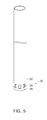
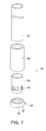
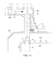
- FIGS. 9 and 11 illustrate a nozzle unit 50 according to another exemplary embodiment.
- nozzle units 50 will be described in detail according to the exemplary embodiments.
- each of the nozzle units 50 is provided on a lower portion of the coating material supply tube 52 through which a solid-phase coating material 10 is supplied.
- the nozzle unit 50 may be connected to the lower portion of the coating material supply tube 52 through a connection tube 58 as illustrated in FIGS. 2 and 3 or may be formed in one piece with the lower portion of the coating material supply tube 52 as illustrated in FIGS. 4 and 5 .
- the nozzle unit 50 Since the nozzle unit 50 is disposed inside the electromagnetic coils 30 of the heating unit 20 and is heated to a high temperature, the nozzle unit 50 may be connected to the lower portion of the coating material supply tube 52 through the connection tube 58 formed of a different material.
- the nozzle unit 50 includes a nozzle 56, and one or more nozzle openings 54 are formed in a sidewall of the nozzle 56, and thus a solid-phase coating material 10 supplied to the inside of the nozzle unit 50 and heated to undergo a phase change into a liquid-phase coating material 12 may be discharged (downwardly) to the coating vapor generating tube 40 through the nozzle openings 54.
- the nozzle 56 has a cylindrical shape with a closed bottom side, and thus a solid-phase coating material 10 falling along the nozzle unit 50 may be accommodated in the nozzle 56.
- the nozzle 56 may have a cylindrical shape and may be formed of a heat-resistant material such as graphite, and a predetermined number of nozzle openings 54 may be formed through the sidewall of the nozzle 56 along the circumference of the nozzle 56.
- connection tube 58 connected between the nozzle 56 and the coating material supply tube 52 may have a cylindrical shape, and may be formed of a non-conductive material such as boron nitride.
- the connection tube 58 formed of a non-conductive material may be connected to the lower portion of the coating material supply tube 52, and the nozzle 56 may be connected to a lower portion of the connection tube 58 to prevent overheating during electromagnetic induction heating.
- the coating material supply tube 52 may be formed of heat-resistant graphite, and may have a cylindrical shape.
- the nozzle 56 and the coating material supply tube 52 located above the nozzle 56 may be formed in one piece without a connection tube therebetween.
- both the nozzle 56 and the coating material supply tube 52 may be formed of graphite.
- the nozzle unit 50 may receive and hold a solid-phase coating material 10 supplied through the coating material supply tube 52 in the form of an ingot, and the solid-phase coating material 10 may be heated and phase-changed into a liquid-phase coating material 12. Then, the liquid-phase coating material 12 may be discharged to the coating vapor generating tube 40 through the nozzle openings 54 formed in the sidewall of the nozzle 56. In the coating vapor generating tube 40 having a concave shape, the liquid-phase coating material 12 may be further heated by electromagnetic induction, and thus coating vapor 14 may be generated.
- the solid-phase coating material 10 may be stably heated and smoothly phase-changed (melted) into a liquid-phase coating material 12.
- coating vapor 14 may also be smoothly generated.
- the heating apparatus 1 of the embodiment may further include a shock-absorbing device 60 disposed on a lower portion of the nozzle 56 of the nozzle unit 50.
- the bottom (not indicated by a reference numeral) of the nozzle 56 of the nozzle unit 50 may be opened, and a holder 62 of the shock-absorbing device 60 may be connected to the lower portion of the nozzle 56.
- the shock-absorbing device 60 may include at least one shock absorber 64 disposed in the holder 62.
- the shock absorber 64 may be a stack of thin heat-resistant sheets capable of absorbing impact force applied by an ingot of a solid-phase coating material 10 falling through the coating material supply tube 10.
- the shock absorber 64 disposed in the holder 62 connected to the lower portion of the nozzle 56 having an opened bottom may be formed of a thin, high-purity alumina sheet capable of withstanding high temperatures.
- the shock-absorbing device 60 may include a liquid-phase coating material receiving part 66 having a height H measured from the bottom of the nozzle 56 formed in one piece with the coating material supply tube 52 or connected to the coating material supply tube 52 through the connection tube 58, and some of a liquid-phase coating material 12 may not be discharged through the nozzle openings 54 but may be accommodated in the liquid-phase coating material receiving part 66.
- the nozzle openings 54 may be densely formed in the sidewall of the nozzle 56 of the nozzle unit 50 of the heating apparatus 1 at regular intervals in the circumferential direction of the nozzle 56, and thus a liquid-phase coating material 12 may be uniformly discharged through the nozzle openings 54 to the coating vapor generating tube 40.
- coating vapor 14 may be smoothly generated.
- the heating apparatus 1 of the embodiment may further include a supply tube blockage prevention unit 70.
- the supply tube blockage prevention unit 70 may include a header 72 movable into the coating material supply tube 52 to initially push a solid-phase coating material 10 into the coating material supply tube 52.
- the supply tube blockage prevention unit 70 may also be used to prevent clogging of the coating material supply tube 52 when coating vapor 14 cools in the coating material supply tube 52.
- the supply tube blockage prevention unit 70 may prevent coating vapor 14 from flowing backward through the coating material supply tube 52.
- the supply tube blockage prevention unit 70 may include a driving unit (vertical driving cylinder) 74 connected to the header 72 through a connecting arm 76 so as to move the header 72 into the coating material supply tube 52.
- a driving unit vertical driving cylinder
- the header 72 of the supply tube blockage prevention unit 70 may have a reverse rectangular shape with a lower end diameter smaller than an upper end diameter, and may be moved at least to a boundary position at which the coating vapor discharge tube 230 and the coating material supply tube 52 meet each other, that is, at least to a boundary region A illustrated in FIGS. 1 , 13 , and 14 .
- a liquid-phase coating material 12 obtained by electromagnetically heating an ingot of a solid-phase coating material 10 placed in the nozzle unit 50 may be discharged to the coating vapor generating tube 40 through the nozzle openings 54 of the nozzle 56. That is, after an ingot of a solid-phase coating material 10 is supplied through the coating material supply tube 52, coating vapor 14 may flow backward along the coating material supply tube 52 through the nozzle openings 54.
- a heating element such as the heating wire 234 may be arranged around the coating vapor discharge tube 230 of the coating machine 200 so as to maintain the coating vapor discharge tube 230 at a predetermined temperature or higher, thus preventing cooling of coating vapor 14 flowing along the coating vapor discharge tube 230 toward a steel sheet 210.
- a portion of the coating material supply tube 52 located inside the coating vapor discharge tube 230 may be maintained at a relatively high temperature, and thus may not be clogged with coating vapor 14 flowing backward in the portion of the coating material supply tube 52 because the coating vapor 14 is not cooled.
- coating vapor 14 flowing backward in a portion of the coating material supply tube 52 located outside the coating vapor discharge tube 40 may be cooled and phase-changed to become solid, and thus the coating material supply tube 52 may be clogged.
- the driving unit (vertical driving cylinder) 72 if the driving unit (vertical driving cylinder) 72 is operated, the header 74 of the supply tube blockage prevention unit 70 connected to the driving unit 72 through the connecting rod 76 is moved at least to the boundary region A (refer to FIGS. 1 , 13 , and 14 ) in which the coating vapor discharge tube 230 and the coating material supply tube 52 meet each other, thereby blocking coating vapor 14 flowing backward in the coating material supply tube 52.
- coating vapor 14 may not be discharged through an upper entrance of the coating material supply tube 52.
- the coating material supply tube 52 connected to an upper portion of the nozzle unit 50 extends through a wall of the vacuum chamber 220 and reaches a coating material supply unit 80 or 90 (described later in detail with reference to FIGS. 1 , 13 , and 14 ), and thus ingots of a solid-phase coating material 10 may be sequentially supplied from the coating material supply unit 80 or 90 to the coating material supply tube 52.
- the coating material supply tube 52 may extend through walls of the vacuum chamber 220 and the coating vapor discharge tube 230 (or the coating vapor generating tube 40) in a hermetically sealed state so as to prevent leakage of coating vapor 14 or introduction of ambient air into the vacuum chamber 220.
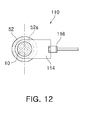
- a supply tube blocking unit 110 may be connected to a portion of the coating material supply tube 52 so as to control the supply of a solid-phase coating material 10 and prevent coating vapor 14 from flowing backward through the coating material supply tube 52.
- the supply tube blocking unit 110 may be disposed on the vacuum chamber 220 at a boundary position between the vacuum chamber 220 and the coating material supply tube 52 extending into the vacuum chamber 220.
- an opening 52a having a semicircular shape centered on the centerline of the coating material supply tube 52 may be formed in the coating material supply tube 52, and a blocking plate 114 having a semicircular end portion may be connected through a connector 116 to a cylinder 112 disposed on the vacuum chamber 220.
- the blocking plate 114 may be moved into the coating material supply tube 52, and an edge of the blocking plate 114 may be brought into contact with an inner lateral surface of the coating material supply tube 52, thereby blocking the coating material supply tube 52.
- a sealing material 114a may be provided on the blocking plate 114 to securely seal the opening 52a of the coating material supply tube 52.
- the blocking plate 114 of the supply tube blocking unit 110 may be used to adjust the amount of a solid-phase coating material 10 supplied through the coating material supply tube 52 and may be operated in association with the header 72 of the supply tube blockage prevention unit 70 so as to block the coating material supply tube 52 when the header 72 is placed above the blocking plate 114.
- backflow of coating vapor 14 may be blocked by downwardly moving the header 72 of the supply tube blockage prevention unit 70 toward the boundary region A between the coating vapor discharge tube 230 and the coating material supply tube 52.
- the blocking plate 114 used to adjust the supply of a solid-phase coating material 10 may also be used to block backflow of coating vapor 14.
- the blocking plate 114 may be moved into the coating material supply tube 52 to receive an intended number of ingots of a solid-phase coating material 10, and may then be moved backward to supply the intended number of ingots of the solid-phase coating material 10 to the nozzle unit 50. In this manner, the supply of the solid-phase coating material 10 may be adjusted using the blocking plate 114.
- the coating material supply unit 80 or 90 may supply a solid-phase coating material 10 to the coating material supply tube 52 connected to the nozzle unit 50 of the heating apparatus 1 of the coating machine 200.
- the coating material supply unit 80 illustrated in FIG. 13 is a modification of the coating material supply unit 80 illustrated in FIG. 1 , and the coating material supply units 80 illustrated in FIGS. 1 and 13 have similar structures.
- the coating material supply unit 90 is illustrated in FIG. 14 according to another embodiment of the present disclosure.
- a steel sheet 210 is vertically transferred, and in the coating machine 200 illustrated in FIG. 14 , a steel sheet 210 is horizontally transferred.
- the vacuum chambers 220, the heating units 20, and the coating vapor discharge tubes 230 of the coating machines 200 illustrated in FIGS. 1 , 13 , and 14 are different, the coating material supply units 80 and 90 of the coating machines 200 have the same basic structure.
- the coating material supply unit 80 connected to the coating material supply tube 52 may basically include a rotary stack 83 rotatably disposed in a cylindrical housing 81 and having coating material containing parts 82 in which ingots of a solid-phase coating material 10 are contained.
- the rotary stack 83 may have a multiple structure, or the coating material containing parts 82 may be vertically formed through the rotary stack 83.
- the rotary stack 83 of the coating material supply unit 80 may have a vertically extending cylindrical shape in which the coating material containing parts 82 are formed, and ingots of a solid-phase coating material 10 fed through a hole (not shown) formed in an upper side of the housing 81 may be placed in the coating material containing parts 82 in multiple layers.
- a pushing part 89a connected to a rod of a cylinder 89 horizontally disposed with respect to the casing 88 may push the ingot of the solid-phase coating material 10 toward an opposite side of the casing 88, that is, toward the upper entrance of the coating material supply tube 52.
- the ingot of the solid-phase coating material 10 may be fed into the nozzle unit 50 through the coating material supply tube 52.
- the rotary stack 83 of the coating material supply unit 80 may be rotated together with a rotation shaft 86 coupled to the housing 81 using a part such as a bearing and connected to a motor 84 through a belt 85 (or a chain) .
- the rotary stack 83 may sequentially supply ingots of the solid-phase coating material 10 to the coating material supply tube 52 while being rotated by a predetermined amount per rotation.
- the rotation shaft 86 coupled to the rotary stack 83 may be directly connected to the motor 84 disposed on an upper side of the housing 81, and may be rotated by the motor 84.
- the coating material supply units 80 illustrated in FIGS. 1 and 13 may only be different in the arrangement of the rotary stack 83 and the motor 84.
- the motor 84 and the cylinder 89 having a horizontal operational range are arranged in such a manner that the motor 84 and the cylinder 89 may not interfere with each other.
- the heating apparatus 1 of the embodiment may further include a preheating unit 100 disposed in the coating material supply unit 80.
- a preheating unit (not shown) may also be disposed in the coating material supply unit 90 illustrated in FIG. 14 .
- the preheating unit 100 may include a heating wire or another heating element vertically arranged in a one-piece center portion of the rotary stack 83 of the coating material supply unit 80 to which the rotation shaft 86 is connected.
- the preheating unit 100 may preheat a solid-phase coating material 10, and then the solid-phase coating material 10 may be supplied to the nozzle 56 of the nozzle unit 50 through the coating material supply tube 52.
- the solid-phase coating material 10 may easily be phase-changed (melted) into a liquid-phase coating material 12 by electromagnetic induction heating, and as a result, coating vapor 14 may be smoothly generated.
- the coating material supply unit 90 includes a circular rotary feeder 93 disposed in a casing 91 located at a side of the vacuum chamber 220 of the coating machine 200, and a motor 92 is connected to an upper side of the rotary feeder 93.
- the rotary feeder 93 includes a plurality of coating material containing parts 94 arranged at predetermined intervals.
- ingots of a solid-phase coating material 10 continuously supplied using a device such as a belt conveyor 95 may be sequentially fed into the coating material containing parts 94 of the rotary feeder 93 through an opening (not shown) of the casing 91, and as the rotary feeder 93 is rotated, the ingots of the solid-phase coating material 10 may be supplied to the nozzle unit 50 disposed in the heating unit 20 through an outlet (not shown) formed in a bottom side of the casing 91 and the coating material supply tube 52.
- the coating material supply tube 52 may be horizontal at least until the coating material supply tube 52 meets the coating vapor discharge tube 230 in the boundary region A therebetween, so as to allow the header 72 of the supply tube blockage prevention unit 70 to move into the coating material supply tube 52.
- the header 72 may enter into the coating material supply tube 52 through an opening (not shown) formed in a boundary portion of the coating material supply tube 52 between a horizontal portion and a vertical portion connected to the coating material supply unit 90.
- the header 72 may push a solid-phase coating material 10 in the coating material supply tube 52 toward the nozzle unit 50 while closing the opening of the coating material supply tube 52.
- the nozzle unit 50 in which a solid-phase coating material 10 is accommodated and phase-changed into a liquid-phase coating material 12 may be disposed inside the electromagnetic coils 30 of the heating unit 20 between the upper electromagnetic coil 32 and the lower electromagnetic coil 34 of the electromagnetic coils 30 as illustrated FIGS. 1 , 13 , and 14 .
- the electromagnetic coils 30 of the heating apparatus 1 may be arranged outside the vacuum chamber 220 and exposed to ambient air as illustrated in FIGS. 1 and 13 or inside the vacuum chamber 220 as illustrated in FIG. 14 .
- the electromagnetic coils 30 may surround an insulative flange 240 coupled to the vacuum chamber 220. That is, the insulative flange 240 may surround the coating vapor generating tube 40 of the heating unit 20 kept in a vacuum and may function as a barrier between the coating vapor generating tube 40 and the electromagnetic coils 30 exposed to ambient air.
- a liquid-phase supply method is used.
- a supplied solid-phase coating material is accommodated in the nozzle 56 and heated to obtain a liquid-phase coating material, and the liquid-phase coating material is supplied to the heating unit 20. Therefore, coating vapor may be generated smoothly and stably.
- a supplied solid-phase coating material may be preheated, and backflow of coating vapor may be blocked at a predetermined position so as to prevent clogging of the coating material supply tube 52. Therefore, a rapidly moving steel sheet may be coated with high quality and productivity.
Landscapes
- Chemical & Material Sciences (AREA)
- Chemical Kinetics & Catalysis (AREA)
- Engineering & Computer Science (AREA)
- Materials Engineering (AREA)
- Mechanical Engineering (AREA)
- Metallurgy (AREA)
- Organic Chemistry (AREA)
- Physical Vapour Deposition (AREA)
- Coating Apparatus (AREA)
- Application Of Or Painting With Fluid Materials (AREA)
- Nozzles (AREA)
Applications Claiming Priority (2)
| Application Number | Priority Date | Filing Date | Title |
|---|---|---|---|
| PCT/KR2013/011855 WO2015093649A1 (fr) | 2013-12-19 | 2013-12-19 | Dispositif de chauffage et mécanisme d'application de revêtement le comprenant |
| KR1020130158862A KR101611669B1 (ko) | 2013-12-19 | 2013-12-19 | 가열장치 및 이를 포함하는 코팅기구 |
Publications (3)
| Publication Number | Publication Date |
|---|---|
| EP3085808A4 EP3085808A4 (fr) | 2016-10-26 |
| EP3085808A1 true EP3085808A1 (fr) | 2016-10-26 |
| EP3085808B1 EP3085808B1 (fr) | 2019-03-20 |
Family
ID=53402981
Family Applications (1)
| Application Number | Title | Priority Date | Filing Date |
|---|---|---|---|
| EP13899655.8A Active EP3085808B1 (fr) | 2013-12-19 | 2013-12-19 | Dispositif de chauffage et mécanisme d'application de revêtement le comprenant |
Country Status (6)
| Country | Link |
|---|---|
| US (1) | US20160312356A1 (fr) |
| EP (1) | EP3085808B1 (fr) |
| JP (1) | JP6303014B2 (fr) |
| KR (1) | KR101611669B1 (fr) |
| CN (1) | CN105829573B (fr) |
| WO (1) | WO2015093649A1 (fr) |
Families Citing this family (10)
| Publication number | Priority date | Publication date | Assignee | Title |
|---|---|---|---|---|
| KR101777777B1 (ko) * | 2015-12-23 | 2017-09-26 | 주식회사 포스코 | 고속 코팅용 진공 증착 장치 |
| TWI737718B (zh) * | 2016-04-25 | 2021-09-01 | 美商創新先進材料股份有限公司 | 含有瀉流源的沉積系統及相關方法 |
| KR102098452B1 (ko) * | 2017-09-11 | 2020-04-07 | 주식회사 포스코 | 건식 도금 장치 및 건식 도금 방법 |
| CN109930113A (zh) * | 2017-12-15 | 2019-06-25 | 合肥鑫晟光电科技有限公司 | 蒸镀装置 |
| KR102098455B1 (ko) * | 2017-12-26 | 2020-04-07 | 주식회사 포스코 | 연속 증착 장치 및 연속 증착 방법 |
| CN108045069B (zh) * | 2018-01-12 | 2023-07-14 | 西安航空学院 | 层状金属复合板材制备装置及其使用方法 |
| JP7667803B2 (ja) * | 2020-06-04 | 2025-04-23 | アプライド マテリアルズ インコーポレイテッド | 気相堆積装置及び真空チャンバ内で基板をコーティングするための方法 |
| DE102021112504A1 (de) | 2021-05-12 | 2022-11-17 | VON ARDENNE Asset GmbH & Co. KG | Verfahren und Beschichtungsanordnung |
| KR102635027B1 (ko) * | 2021-09-23 | 2024-02-07 | 이병철 | 초발수 스핀코팅 방법 및 초발수 스핀코팅 장치 |
| CN117680331A (zh) * | 2023-11-02 | 2024-03-12 | 中南大学 | 一种用于表面涂覆的设备及方法 |
Family Cites Families (15)
| Publication number | Priority date | Publication date | Assignee | Title |
|---|---|---|---|---|
| US2909149A (en) * | 1957-11-15 | 1959-10-20 | Cons Electrodynamics Corp | Apparatus for evaporating metal |
| JPS55154537A (en) | 1979-05-18 | 1980-12-02 | Mitsubishi Heavy Ind Ltd | Method and apparatus for carrying molten metal |
| JPS6447844A (en) * | 1987-08-12 | 1989-02-22 | Toyota Central Res & Dev | Method and apparatus for treating surface |
| US6251233B1 (en) * | 1998-08-03 | 2001-06-26 | The Coca-Cola Company | Plasma-enhanced vacuum vapor deposition system including systems for evaporation of a solid, producing an electric arc discharge and measuring ionization and evaporation |
| US20050229856A1 (en) | 2004-04-20 | 2005-10-20 | Malik Roger J | Means and method for a liquid metal evaporation source with integral level sensor and external reservoir |
| KR20070015923A (ko) | 2004-05-27 | 2007-02-06 | 시드라베, 인크. | 금속 및 금속 합금을 증발시키기 위한 진공 증착 방법 및장치 |
| JP2006083427A (ja) * | 2004-09-16 | 2006-03-30 | Sanritsuku:Kk | 蒸着用発熱体 |
| FR2882064B1 (fr) * | 2005-02-17 | 2007-05-11 | Snecma Propulsion Solide Sa | Procede de densification de substrats poreux minces par infiltration chimique en phase vapeur et dispositif de chargement de tels substrats |
| US20070141233A1 (en) * | 2005-12-21 | 2007-06-21 | United Technologies Corporation | EB-PVD system with automatic melt pool height control |
| ATE526431T1 (de) | 2006-09-29 | 2011-10-15 | Ardenne Anlagentech Gmbh | Vakuumbeschichtungsverfahren und anordnung zur durchführung des verfahrens |
| KR101103508B1 (ko) * | 2009-02-10 | 2012-01-06 | 한국생산기술연구원 | 선형 유기물 증착 장치 |
| JP2010189739A (ja) | 2009-02-20 | 2010-09-02 | Mitsubishi Heavy Ind Ltd | 蒸発装置 |
| KR101207719B1 (ko) * | 2010-12-27 | 2012-12-03 | 주식회사 포스코 | 건식 코팅 장치 |
| JP2013127086A (ja) * | 2011-12-16 | 2013-06-27 | Ulvac Japan Ltd | 蒸着装置及び蒸着方法 |
| KR101461738B1 (ko) * | 2012-12-21 | 2014-11-14 | 주식회사 포스코 | 가열장치 및 이를 포함하는 코팅 시스템 |
-
2013
- 2013-12-19 US US15/102,839 patent/US20160312356A1/en not_active Abandoned
- 2013-12-19 WO PCT/KR2013/011855 patent/WO2015093649A1/fr not_active Ceased
- 2013-12-19 CN CN201380081749.7A patent/CN105829573B/zh not_active Expired - Fee Related
- 2013-12-19 KR KR1020130158862A patent/KR101611669B1/ko active Active
- 2013-12-19 EP EP13899655.8A patent/EP3085808B1/fr active Active
- 2013-12-19 JP JP2016541228A patent/JP6303014B2/ja not_active Expired - Fee Related
Also Published As
| Publication number | Publication date |
|---|---|
| EP3085808B1 (fr) | 2019-03-20 |
| US20160312356A1 (en) | 2016-10-27 |
| EP3085808A4 (fr) | 2016-10-26 |
| JP6303014B2 (ja) | 2018-03-28 |
| CN105829573B (zh) | 2018-08-24 |
| KR20150071832A (ko) | 2015-06-29 |
| JP2017500449A (ja) | 2017-01-05 |
| WO2015093649A8 (fr) | 2015-08-13 |
| KR101611669B1 (ko) | 2016-04-12 |
| CN105829573A (zh) | 2016-08-03 |
| WO2015093649A1 (fr) | 2015-06-25 |
Similar Documents
| Publication | Publication Date | Title |
|---|---|---|
| EP3085808B1 (fr) | Dispositif de chauffage et mécanisme d'application de revêtement le comprenant | |
| US10196736B2 (en) | Heating apparatus, and coating device comprising same | |
| US7339139B2 (en) | Multi-layered radiant thermal evaporator and method of use | |
| EP2652167B1 (fr) | Appareil de revêtement continu | |
| EP2746423B1 (fr) | Système de dépôt, appareil de dépôt et procédé de fonctionnement | |
| KR102303175B1 (ko) | 진공증착장치 | |
| EP2659022B1 (fr) | Appareil de revêtement à sec | |
| CN107109626A (zh) | 用于在部件、带状材料或工具的表面上形成涂层的装置 | |
| CN113005512B (zh) | 一种碳化硅单晶锭生长设备及方法 | |
| US20110268893A1 (en) | Thin film manufacturing device and thin film manufacturing method | |
| US20240117484A1 (en) | Evaporation apparatus, vapor deposition apparatus, and evaporation method | |
| KR20180047087A (ko) | 유도 가열 증발 증착 장치 | |
| KR20110002235A (ko) | 하향식 선형 증발원 및 이를 이용한 박막 형성 장치 | |
| US20140302238A1 (en) | Apparatus and Method for the Evaporation and Deposition of Materials | |
| KR101543953B1 (ko) | 고상금속 공급장치와 이를 포함한 진공 증착장치 및 고상금속 공급방법 | |
| CN111621749A (zh) | 供应装置、方法和处理装置 | |
| TW202025243A (zh) | 輻射裝置、用於在一基板上沉積一材料的沉積設備、及利用一沉積設備用於在一基板上沉積一材料的方法 |
Legal Events
| Date | Code | Title | Description |
|---|---|---|---|
| PUAI | Public reference made under article 153(3) epc to a published international application that has entered the european phase |
Free format text: ORIGINAL CODE: 0009012 |
|
| 17P | Request for examination filed |
Effective date: 20160613 |
|
| A4 | Supplementary search report drawn up and despatched |
Effective date: 20160817 |
|
| AK | Designated contracting states |
Kind code of ref document: A1 Designated state(s): AL AT BE BG CH CY CZ DE DK EE ES FI FR GB GR HR HU IE IS IT LI LT LU LV MC MK MT NL NO PL PT RO RS SE SI SK SM TR |
|
| AX | Request for extension of the european patent |
Extension state: BA ME |
|
| DAX | Request for extension of the european patent (deleted) | ||
| STAA | Information on the status of an ep patent application or granted ep patent |
Free format text: STATUS: EXAMINATION IS IN PROGRESS |
|
| 17Q | First examination report despatched |
Effective date: 20171102 |
|
| GRAP | Despatch of communication of intention to grant a patent |
Free format text: ORIGINAL CODE: EPIDOSNIGR1 |
|
| STAA | Information on the status of an ep patent application or granted ep patent |
Free format text: STATUS: GRANT OF PATENT IS INTENDED |
|
| INTG | Intention to grant announced |
Effective date: 20180613 |
|
| GRAS | Grant fee paid |
Free format text: ORIGINAL CODE: EPIDOSNIGR3 |
|
| GRAJ | Information related to disapproval of communication of intention to grant by the applicant or resumption of examination proceedings by the epo deleted |
Free format text: ORIGINAL CODE: EPIDOSDIGR1 |
|
| GRAL | Information related to payment of fee for publishing/printing deleted |
Free format text: ORIGINAL CODE: EPIDOSDIGR3 |
|
| STAA | Information on the status of an ep patent application or granted ep patent |
Free format text: STATUS: EXAMINATION IS IN PROGRESS |
|
| GRAP | Despatch of communication of intention to grant a patent |
Free format text: ORIGINAL CODE: EPIDOSNIGR1 |
|
| STAA | Information on the status of an ep patent application or granted ep patent |
Free format text: STATUS: GRANT OF PATENT IS INTENDED |
|
| INTC | Intention to grant announced (deleted) | ||
| INTG | Intention to grant announced |
Effective date: 20181126 |
|
| GRAA | (expected) grant |
Free format text: ORIGINAL CODE: 0009210 |
|
| STAA | Information on the status of an ep patent application or granted ep patent |
Free format text: STATUS: THE PATENT HAS BEEN GRANTED |
|
| AK | Designated contracting states |
Kind code of ref document: B1 Designated state(s): AL AT BE BG CH CY CZ DE DK EE ES FI FR GB GR HR HU IE IS IT LI LT LU LV MC MK MT NL NO PL PT RO RS SE SI SK SM TR |
|
| REG | Reference to a national code |
Ref country code: GB Ref legal event code: FG4D |
|
| REG | Reference to a national code |
Ref country code: CH Ref legal event code: EP |
|
| REG | Reference to a national code |
Ref country code: DE Ref legal event code: R096 Ref document number: 602013052791 Country of ref document: DE |
|
| REG | Reference to a national code |
Ref country code: AT Ref legal event code: REF Ref document number: 1110607 Country of ref document: AT Kind code of ref document: T Effective date: 20190415 |
|
| REG | Reference to a national code |
Ref country code: IE Ref legal event code: FG4D |
|
| REG | Reference to a national code |
Ref country code: NL Ref legal event code: FP |
|
| PG25 | Lapsed in a contracting state [announced via postgrant information from national office to epo] |
Ref country code: LT Free format text: LAPSE BECAUSE OF FAILURE TO SUBMIT A TRANSLATION OF THE DESCRIPTION OR TO PAY THE FEE WITHIN THE PRESCRIBED TIME-LIMIT Effective date: 20190320 Ref country code: FI Free format text: LAPSE BECAUSE OF FAILURE TO SUBMIT A TRANSLATION OF THE DESCRIPTION OR TO PAY THE FEE WITHIN THE PRESCRIBED TIME-LIMIT Effective date: 20190320 Ref country code: SE Free format text: LAPSE BECAUSE OF FAILURE TO SUBMIT A TRANSLATION OF THE DESCRIPTION OR TO PAY THE FEE WITHIN THE PRESCRIBED TIME-LIMIT Effective date: 20190320 Ref country code: NO Free format text: LAPSE BECAUSE OF FAILURE TO SUBMIT A TRANSLATION OF THE DESCRIPTION OR TO PAY THE FEE WITHIN THE PRESCRIBED TIME-LIMIT Effective date: 20190620 |
|
| REG | Reference to a national code |
Ref country code: LT Ref legal event code: MG4D |
|
| PG25 | Lapsed in a contracting state [announced via postgrant information from national office to epo] |
Ref country code: GR Free format text: LAPSE BECAUSE OF FAILURE TO SUBMIT A TRANSLATION OF THE DESCRIPTION OR TO PAY THE FEE WITHIN THE PRESCRIBED TIME-LIMIT Effective date: 20190621 Ref country code: BG Free format text: LAPSE BECAUSE OF FAILURE TO SUBMIT A TRANSLATION OF THE DESCRIPTION OR TO PAY THE FEE WITHIN THE PRESCRIBED TIME-LIMIT Effective date: 20190620 Ref country code: RS Free format text: LAPSE BECAUSE OF FAILURE TO SUBMIT A TRANSLATION OF THE DESCRIPTION OR TO PAY THE FEE WITHIN THE PRESCRIBED TIME-LIMIT Effective date: 20190320 Ref country code: HR Free format text: LAPSE BECAUSE OF FAILURE TO SUBMIT A TRANSLATION OF THE DESCRIPTION OR TO PAY THE FEE WITHIN THE PRESCRIBED TIME-LIMIT Effective date: 20190320 Ref country code: LV Free format text: LAPSE BECAUSE OF FAILURE TO SUBMIT A TRANSLATION OF THE DESCRIPTION OR TO PAY THE FEE WITHIN THE PRESCRIBED TIME-LIMIT Effective date: 20190320 |
|
| REG | Reference to a national code |
Ref country code: AT Ref legal event code: MK05 Ref document number: 1110607 Country of ref document: AT Kind code of ref document: T Effective date: 20190320 |
|
| PG25 | Lapsed in a contracting state [announced via postgrant information from national office to epo] |
Ref country code: AL Free format text: LAPSE BECAUSE OF FAILURE TO SUBMIT A TRANSLATION OF THE DESCRIPTION OR TO PAY THE FEE WITHIN THE PRESCRIBED TIME-LIMIT Effective date: 20190320 Ref country code: PT Free format text: LAPSE BECAUSE OF FAILURE TO SUBMIT A TRANSLATION OF THE DESCRIPTION OR TO PAY THE FEE WITHIN THE PRESCRIBED TIME-LIMIT Effective date: 20190720 Ref country code: EE Free format text: LAPSE BECAUSE OF FAILURE TO SUBMIT A TRANSLATION OF THE DESCRIPTION OR TO PAY THE FEE WITHIN THE PRESCRIBED TIME-LIMIT Effective date: 20190320 Ref country code: SK Free format text: LAPSE BECAUSE OF FAILURE TO SUBMIT A TRANSLATION OF THE DESCRIPTION OR TO PAY THE FEE WITHIN THE PRESCRIBED TIME-LIMIT Effective date: 20190320 Ref country code: IT Free format text: LAPSE BECAUSE OF FAILURE TO SUBMIT A TRANSLATION OF THE DESCRIPTION OR TO PAY THE FEE WITHIN THE PRESCRIBED TIME-LIMIT Effective date: 20190320 Ref country code: RO Free format text: LAPSE BECAUSE OF FAILURE TO SUBMIT A TRANSLATION OF THE DESCRIPTION OR TO PAY THE FEE WITHIN THE PRESCRIBED TIME-LIMIT Effective date: 20190320 Ref country code: CZ Free format text: LAPSE BECAUSE OF FAILURE TO SUBMIT A TRANSLATION OF THE DESCRIPTION OR TO PAY THE FEE WITHIN THE PRESCRIBED TIME-LIMIT Effective date: 20190320 Ref country code: ES Free format text: LAPSE BECAUSE OF FAILURE TO SUBMIT A TRANSLATION OF THE DESCRIPTION OR TO PAY THE FEE WITHIN THE PRESCRIBED TIME-LIMIT Effective date: 20190320 |
|
| PG25 | Lapsed in a contracting state [announced via postgrant information from national office to epo] |
Ref country code: SM Free format text: LAPSE BECAUSE OF FAILURE TO SUBMIT A TRANSLATION OF THE DESCRIPTION OR TO PAY THE FEE WITHIN THE PRESCRIBED TIME-LIMIT Effective date: 20190320 Ref country code: PL Free format text: LAPSE BECAUSE OF FAILURE TO SUBMIT A TRANSLATION OF THE DESCRIPTION OR TO PAY THE FEE WITHIN THE PRESCRIBED TIME-LIMIT Effective date: 20190320 |
|
| PG25 | Lapsed in a contracting state [announced via postgrant information from national office to epo] |
Ref country code: IS Free format text: LAPSE BECAUSE OF FAILURE TO SUBMIT A TRANSLATION OF THE DESCRIPTION OR TO PAY THE FEE WITHIN THE PRESCRIBED TIME-LIMIT Effective date: 20190720 Ref country code: AT Free format text: LAPSE BECAUSE OF FAILURE TO SUBMIT A TRANSLATION OF THE DESCRIPTION OR TO PAY THE FEE WITHIN THE PRESCRIBED TIME-LIMIT Effective date: 20190320 |
|
| REG | Reference to a national code |
Ref country code: DE Ref legal event code: R097 Ref document number: 602013052791 Country of ref document: DE |
|
| PLBE | No opposition filed within time limit |
Free format text: ORIGINAL CODE: 0009261 |
|
| STAA | Information on the status of an ep patent application or granted ep patent |
Free format text: STATUS: NO OPPOSITION FILED WITHIN TIME LIMIT |
|
| PG25 | Lapsed in a contracting state [announced via postgrant information from national office to epo] |
Ref country code: DK Free format text: LAPSE BECAUSE OF FAILURE TO SUBMIT A TRANSLATION OF THE DESCRIPTION OR TO PAY THE FEE WITHIN THE PRESCRIBED TIME-LIMIT Effective date: 20190320 |
|
| 26N | No opposition filed |
Effective date: 20200102 |
|
| PG25 | Lapsed in a contracting state [announced via postgrant information from national office to epo] |
Ref country code: SI Free format text: LAPSE BECAUSE OF FAILURE TO SUBMIT A TRANSLATION OF THE DESCRIPTION OR TO PAY THE FEE WITHIN THE PRESCRIBED TIME-LIMIT Effective date: 20190320 |
|
| PG25 | Lapsed in a contracting state [announced via postgrant information from national office to epo] |
Ref country code: TR Free format text: LAPSE BECAUSE OF FAILURE TO SUBMIT A TRANSLATION OF THE DESCRIPTION OR TO PAY THE FEE WITHIN THE PRESCRIBED TIME-LIMIT Effective date: 20190320 |
|
| REG | Reference to a national code |
Ref country code: CH Ref legal event code: PL |
|
| PG25 | Lapsed in a contracting state [announced via postgrant information from national office to epo] |
Ref country code: MC Free format text: LAPSE BECAUSE OF FAILURE TO SUBMIT A TRANSLATION OF THE DESCRIPTION OR TO PAY THE FEE WITHIN THE PRESCRIBED TIME-LIMIT Effective date: 20190320 |
|
| PG25 | Lapsed in a contracting state [announced via postgrant information from national office to epo] |
Ref country code: IE Free format text: LAPSE BECAUSE OF NON-PAYMENT OF DUE FEES Effective date: 20191219 Ref country code: LU Free format text: LAPSE BECAUSE OF NON-PAYMENT OF DUE FEES Effective date: 20191219 |
|
| PG25 | Lapsed in a contracting state [announced via postgrant information from national office to epo] |
Ref country code: LI Free format text: LAPSE BECAUSE OF NON-PAYMENT OF DUE FEES Effective date: 20191231 Ref country code: CH Free format text: LAPSE BECAUSE OF NON-PAYMENT OF DUE FEES Effective date: 20191231 |
|
| PG25 | Lapsed in a contracting state [announced via postgrant information from national office to epo] |
Ref country code: CY Free format text: LAPSE BECAUSE OF FAILURE TO SUBMIT A TRANSLATION OF THE DESCRIPTION OR TO PAY THE FEE WITHIN THE PRESCRIBED TIME-LIMIT Effective date: 20190320 |
|
| PG25 | Lapsed in a contracting state [announced via postgrant information from national office to epo] |
Ref country code: HU Free format text: LAPSE BECAUSE OF FAILURE TO SUBMIT A TRANSLATION OF THE DESCRIPTION OR TO PAY THE FEE WITHIN THE PRESCRIBED TIME-LIMIT; INVALID AB INITIO Effective date: 20131219 Ref country code: MT Free format text: LAPSE BECAUSE OF FAILURE TO SUBMIT A TRANSLATION OF THE DESCRIPTION OR TO PAY THE FEE WITHIN THE PRESCRIBED TIME-LIMIT Effective date: 20190320 |
|
| PGFP | Annual fee paid to national office [announced via postgrant information from national office to epo] |
Ref country code: GB Payment date: 20211122 Year of fee payment: 9 Ref country code: FR Payment date: 20211125 Year of fee payment: 9 Ref country code: NL Payment date: 20211123 Year of fee payment: 9 |
|
| PGFP | Annual fee paid to national office [announced via postgrant information from national office to epo] |
Ref country code: BE Payment date: 20211123 Year of fee payment: 9 |
|
| PG25 | Lapsed in a contracting state [announced via postgrant information from national office to epo] |
Ref country code: MK Free format text: LAPSE BECAUSE OF FAILURE TO SUBMIT A TRANSLATION OF THE DESCRIPTION OR TO PAY THE FEE WITHIN THE PRESCRIBED TIME-LIMIT Effective date: 20190320 |
|
| REG | Reference to a national code |
Ref country code: DE Ref legal event code: R081 Ref document number: 602013052791 Country of ref document: DE Owner name: POSCO CO., LTD, POHANG-SI, KR Free format text: FORMER OWNER: POSCO, POHANG-SI, GYEONGSANGBUK-DO, KR Ref country code: DE Ref legal event code: R081 Ref document number: 602013052791 Country of ref document: DE Owner name: POSCO CO., LTD, POHANG- SI, KR Free format text: FORMER OWNER: POSCO, POHANG-SI, GYEONGSANGBUK-DO, KR Ref country code: DE Ref legal event code: R081 Ref document number: 602013052791 Country of ref document: DE Owner name: POSCO HOLDINGS INC., KR Free format text: FORMER OWNER: POSCO, POHANG-SI, GYEONGSANGBUK-DO, KR |
|
| REG | Reference to a national code |
Ref country code: NL Ref legal event code: PD Owner name: POSCO HOLDINGS INC.; KR Free format text: DETAILS ASSIGNMENT: CHANGE OF OWNER(S), CHANGE OF LEGAL ENTITY; FORMER OWNER NAME: POSCO Effective date: 20221026 |
|
| REG | Reference to a national code |
Ref country code: GB Ref legal event code: 732E Free format text: REGISTERED BETWEEN 20221027 AND 20221102 |
|
| REG | Reference to a national code |
Ref country code: NL Ref legal event code: PD Owner name: POSCO CO., LTD; KO Free format text: DETAILS ASSIGNMENT: CHANGE OF OWNER(S), ASSIGNMENT; FORMER OWNER NAME: POSCO Effective date: 20221109 |
|
| REG | Reference to a national code |
Ref country code: BE Ref legal event code: PD Owner name: POSCO CO., LTD; KR Free format text: DETAILS ASSIGNMENT: CHANGE OF OWNER(S), ASSIGNMENT; FORMER OWNER NAME: POSCO HOLDINGS INC. Effective date: 20221209 Ref country code: BE Ref legal event code: HC Owner name: POSCO HOLDINGS INC.; KR Free format text: DETAILS ASSIGNMENT: CHANGE OF OWNER(S), CHANGE OF OWNER(S) NAME; FORMER OWNER NAME: POSCO Effective date: 20221209 |
|
| REG | Reference to a national code |
Ref country code: DE Ref legal event code: R081 Ref document number: 602013052791 Country of ref document: DE Owner name: POSCO CO., LTD, POHANG-SI, KR Free format text: FORMER OWNER: POSCO HOLDINGS INC., SEOUL, KR Ref country code: DE Ref legal event code: R081 Ref document number: 602013052791 Country of ref document: DE Owner name: POSCO CO., LTD, POHANG- SI, KR Free format text: FORMER OWNER: POSCO HOLDINGS INC., SEOUL, KR |
|
| REG | Reference to a national code |
Ref country code: NL Ref legal event code: MM Effective date: 20230101 |
|
| GBPC | Gb: european patent ceased through non-payment of renewal fee |
Effective date: 20221219 |
|
| REG | Reference to a national code |
Ref country code: BE Ref legal event code: MM Effective date: 20221231 |
|
| PG25 | Lapsed in a contracting state [announced via postgrant information from national office to epo] |
Ref country code: NL Free format text: LAPSE BECAUSE OF NON-PAYMENT OF DUE FEES Effective date: 20230101 |
|
| PG25 | Lapsed in a contracting state [announced via postgrant information from national office to epo] |
Ref country code: GB Free format text: LAPSE BECAUSE OF NON-PAYMENT OF DUE FEES Effective date: 20221219 |
|
| PG25 | Lapsed in a contracting state [announced via postgrant information from national office to epo] |
Ref country code: FR Free format text: LAPSE BECAUSE OF NON-PAYMENT OF DUE FEES Effective date: 20221231 Ref country code: BE Free format text: LAPSE BECAUSE OF NON-PAYMENT OF DUE FEES Effective date: 20221231 |
|
| PGFP | Annual fee paid to national office [announced via postgrant information from national office to epo] |
Ref country code: DE Payment date: 20251222 Year of fee payment: 13 |