EP3085837A1 - Dispositif d'appui comprenant une caisse grillagee - Google Patents
Dispositif d'appui comprenant une caisse grillagee Download PDFInfo
- Publication number
- EP3085837A1 EP3085837A1 EP16164589.0A EP16164589A EP3085837A1 EP 3085837 A1 EP3085837 A1 EP 3085837A1 EP 16164589 A EP16164589 A EP 16164589A EP 3085837 A1 EP3085837 A1 EP 3085837A1
- Authority
- EP
- European Patent Office
- Prior art keywords
- mesh
- box
- plate
- fastening means
- counter
- Prior art date
- Legal status (The legal status is an assumption and is not a legal conclusion. Google has not performed a legal analysis and makes no representation as to the accuracy of the status listed.)
- Withdrawn
Links
- 239000000463 material Substances 0.000 claims abstract description 33
- 239000000945 filler Substances 0.000 claims abstract description 5
- 238000005253 cladding Methods 0.000 claims description 17
- 239000002184 metal Substances 0.000 claims description 8
- 239000002023 wood Substances 0.000 claims description 6
- 239000004033 plastic Substances 0.000 claims description 5
- 239000004567 concrete Substances 0.000 claims description 4
- 229910000831 Steel Inorganic materials 0.000 claims description 3
- 239000000919 ceramic Substances 0.000 claims description 3
- 239000010959 steel Substances 0.000 claims description 3
- NIXOWILDQLNWCW-UHFFFAOYSA-N acrylic acid group Chemical group C(C=C)(=O)O NIXOWILDQLNWCW-UHFFFAOYSA-N 0.000 claims description 2
- 239000007799 cork Substances 0.000 claims description 2
- 229910052500 inorganic mineral Inorganic materials 0.000 claims description 2
- 238000003780 insertion Methods 0.000 claims description 2
- 230000037431 insertion Effects 0.000 claims description 2
- 239000011707 mineral Substances 0.000 claims description 2
- 239000000203 mixture Substances 0.000 claims description 2
- 239000011347 resin Substances 0.000 claims description 2
- 229920005989 resin Polymers 0.000 claims description 2
- 239000000758 substrate Substances 0.000 claims description 2
- 239000004575 stone Substances 0.000 description 5
- 238000010276 construction Methods 0.000 description 3
- 238000013461 design Methods 0.000 description 3
- 239000006096 absorbing agent Substances 0.000 description 2
- 238000005338 heat storage Methods 0.000 description 2
- 230000035939 shock Effects 0.000 description 2
- 229910001335 Galvanized steel Inorganic materials 0.000 description 1
- 238000010521 absorption reaction Methods 0.000 description 1
- 238000009825 accumulation Methods 0.000 description 1
- 239000013590 bulk material Substances 0.000 description 1
- 238000005260 corrosion Methods 0.000 description 1
- 230000007797 corrosion Effects 0.000 description 1
- 230000001419 dependent effect Effects 0.000 description 1
- 238000011161 development Methods 0.000 description 1
- 230000018109 developmental process Effects 0.000 description 1
- 239000008397 galvanized steel Substances 0.000 description 1
- 239000011521 glass Substances 0.000 description 1
- 238000009434 installation Methods 0.000 description 1
- 238000009413 insulation Methods 0.000 description 1
- 238000004519 manufacturing process Methods 0.000 description 1
- 238000000034 method Methods 0.000 description 1
- 230000001681 protective effect Effects 0.000 description 1
- 238000004064 recycling Methods 0.000 description 1
- 239000011376 self-consolidating concrete Substances 0.000 description 1
- 239000002689 soil Substances 0.000 description 1
- 239000010935 stainless steel Substances 0.000 description 1
- 229910001220 stainless steel Inorganic materials 0.000 description 1
- 230000003068 static effect Effects 0.000 description 1
- 238000012549 training Methods 0.000 description 1
Images


Classifications
-
- E—FIXED CONSTRUCTIONS
- E02—HYDRAULIC ENGINEERING; FOUNDATIONS; SOIL SHIFTING
- E02D—FOUNDATIONS; EXCAVATIONS; EMBANKMENTS; UNDERGROUND OR UNDERWATER STRUCTURES
- E02D29/00—Independent underground or underwater structures; Retaining walls
- E02D29/02—Retaining or protecting walls
-
- E—FIXED CONSTRUCTIONS
- E02—HYDRAULIC ENGINEERING; FOUNDATIONS; SOIL SHIFTING
- E02D—FOUNDATIONS; EXCAVATIONS; EMBANKMENTS; UNDERGROUND OR UNDERWATER STRUCTURES
- E02D29/00—Independent underground or underwater structures; Retaining walls
- E02D29/02—Retaining or protecting walls
- E02D29/0208—Gabions
Definitions
- the invention relates to a supporting device with a mesh screen box, which is to be filled to form a wall with filling material, consisting essentially of a mesh material, as well as a mounting bracket.
- Grid baskets are known for filling with stones, which serve as wall replacement. They are, for example, be arranged in front of slopes to prevent soil from slipping, especially on steep slopes or is rinsed in heavy rainfall.
- a typical embodiment is in EP 1712687 A1 shown.
- the disadvantage here is that the grid box is essentially determined by the filled material in appearance and many functions.
- Object of the present invention is to provide, while avoiding the disadvantages of the prior art, a support device that is easy to set up and is easily adaptable to different requirements at least on its surface.
- the invention is a supporting device with a mesh screen box which is to be filled to form a wall with filling material consisting essentially of a mesh material 3 with a mesh holding the filler material 5, wherein at least one fastening means 7 for a releasable attachment of a Covering the mesh lattice box 1 on and / or arranged between and / or behind the mesh material 3 is provided.
- the fastening device 7 may form a substructure for attachment of panels.
- this can be set up as a single wall or also to safely retain underlying material in the form of a mass accumulation in the manner of a retaining wall.
- This can also be ensured by a support element, which is formed projecting in the sense of a support leg from the lower support region, as in the EP 1712687 A1 ,
- the support member extends at least partially longitudinally about one To provide support area for slope or embankment material and / or to provide sufficient footprint.
- the support element can be arranged in a support region between the base and a determined by the size and the shape of the mesh and the mesh thereon impinging forces, higher up area.
- strip-shaped fasteners make it possible to easily and safely attach various veneering and / or protective panels to the mesh screen without compromising their stability.
- a step-by-step construction can be carried out in a simple manner, with the lattice box first being set up with the filling and then the lining being able to be attached. However, this can also be introduced before installation and / or filling if required.
- the mesh grid design allows a very easy training of the support device, which can be prefabricated and also easy to transport.
- material with gaps other than the slope material can be used on and under the support element, for example the same filling material as for filling the mesh lattice box. In this way, a very good drainage of an underlying slope area, for example against dammed rainwater is guaranteed without additional expensive drainage facilities such as concrete drains or the like would have to be arranged there.
- the mesh lattice boxes can be easily manufactured in different sizes and yet provide a pleasingly uniform or variable appearance.
- a fastening device comprises strip-shaped fastening means extending substantially perpendicularly to the mesh lattice box from a standing surface to an upper mesh lattice surface, which are formed in particular on a rear side of the mesh lattice box and / or on a front side.
- the strip-shaped fastening means comprises at least one or more attachment openings 11 for attachment of fasteners, in particular screws, which are provided for the attachment of cladding elements, in particular cladding cross members.
- the fastening device 7 comprises a substantially perpendicular to the mesh grid box 1 extending from the standing surface to an upper mesh grid surface strip-shaped fastening means, which is in particular formed on a back 18 of the mesh grid box 1 and / or on a front side 24.
- the cladding elements wood and / or plastic, in particular mixtures comprising wood chips and resin, which are pressed, and / or acrylic or ceramic plates, cork boards, rubber plates, plastic plates have.
- the mesh material 3 and / or the fastening means 7 comprises a metal, in particular steel, in particular hot-dip galvanized steel or stainless steel.
- an attachment of the substrate of the mesh lattice box 1 is provided, in particular a foundation made of crushed gravel bed, crushed mineral concrete, self-compacting concrete and / or a fundamentally separately prepared foundation.
- a predetermined number of mesh lattice boxes together is strung to achieve a desired length of the metal mesh basket assembly, the individual mesh lattice boxes in particular with a uniform dimension, in particular with a width of about 1 m, are formed.
- Several support devices can be arranged as a support system in modular construction next to each other and thus form a retaining wall to protect against slipping of ramparts, slopes or embankments and allow the different panels a simple change, such as a sound insulation function.
- fixing brackets 40 for the fastening means 7 for releasably securing the panel comprising a support plate 42 on the mesh box 1 with support hooks 43 and extensions 46 extending perpendicularly from the support panel for fixing - e.g. strip-shaped fastening means 7, and a counter-plate 44 in the mesh lattice box 1, wherein counter-plate and support plate are fastened to each other for attaching the panel to the lattice box, and at least one horizontal strut 28 between the carrier and counter-plate 44 is located at the hooks 43rd of the counter plate 44 hang.
- the hooks can be used to stabilize the height of the brackets.
- the support plate 42 is preferably connected via a fastening device (7) with a cladding or cladding substructure (17) releasably connected by screws, nails, pins, click connections.
- the support plate is detachably connected to the counter-plate by means of screws or other known to those skilled in connection devices.
- the carrier sheet is also connected to the strip-shaped fastener by screws, nails, pins.
- the strip-shaped fastening means form a substructure on which the cladding elements are mounted.
- the invention further relates to a mounting bracket 40 for fasteners 7 for releasably securing a panel to metal mesh of a mesh box 1 of a support device 9 according to any one of the preceding claims, comprising a support plate 42 with carrier hooks 43 and extending perpendicularly from the support plate extensions 46 for fixing the fastening means 7 and a counter-plate 44 for insertion into the mesh lattice box 1.
- This clip can also be easily attached to metal grid designs of any kind if the front and back of the metal grid are accessible.
- Fig. 1 schematically represents a perspective side view of a support device 9.
- the support device 9 here has a substantially rectangular cross-section, but also L-shaped devices or other cross sections can be used.
- the support device 9 has a cuboid mesh lattice box 1 whose sides consist of mesh material 3.
- the mesh size 5 of the grid 4 is adapted to the average size of the respective filling body of the filling material 2, so that the filling material remains in the basket.
- the support element 9 is here freestanding - but can also be connected to other elements.
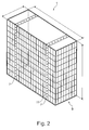
- the support device 9 has in this embodiment substantially on its front side 24 and / or its rear side 18 preferably perpendicularly extending strip-shaped fastening means 7, which may extend further to a filling opening 22 on an upper side 8 of the mesh lattice box 1.
- the fasteners are never bound to the strip form.
- On the fastening means 7 can - as in Fig. 1 to 7 shown - in these figures, not shown lining elements, in particular fairing transverse elements, such as panels, are attached, which can cover the mesh lattice box 1 completely and / or partially.
- the Befest Trentsonsmittet can also be attached to the narrow sides, if the lattice box narrow side is free-standing.
- the body of the support device 9 is in this embodiment advantageously made of steel wires with a thickness of about 5 mm, which are spot-welded at their crossing points.
- the lateral ends of each mesh lattice box are closed with a grid and welded.
- a size which can advantageously be used in the usual way of use is a grid box width on the longitudinal side 6 of about 1000 mm or 800 mm with a height of about 1000 mm and a depth of 400.
- the mesh size 5 of the grid 4 is 50 mm, for example for average filling stone sizes.
- the grid 4 is completely hot-dip galvanized for corrosion protection.
- the mesh size 5 may be about 50 mm x about 50 mm.
- the edges 30 of the support device 9 are welded to ensure greater stability.
- filling of the support device with filling material 2 takes place in the example shown by a filling opening 22 on an upper side 8 of the mesh lattice box 1.
- filler material is for example stone material, but also glass material from a recycling process, rubble and the like. Usable.
- the mesh grid surfaces of various mesh baskets can also be interconnected, thus ensuring a further increased security.
- Fig. 2 shows a perspective view of a support device 9 with strip-shaped fastening means 7 with a plurality of distributed mounting holes 11, where cladding elements for covering the mesh lattice box 1 can be attached.
- These cladding elements may be functional - for example, if solar panels are used as cladding elements - also have the function of passive heat storage by the cladding material or sound absorption or a shock absorber function. These are preferably releasably secured to allow easy replacement according to the wishes of the client.
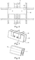
- Fig. 3 shows an embodiment of a mounting bracket 40, which serves for releasably securing fasteners 7, in plan view.
- the bracket 40 consists essentially of a counter-plate 44 and a support plate 42 with fastening extension 46.
- the support plate 42 has here two welded, perpendicular to a support plate 42 with hooks for carrying the clip and connecting means for connection to the counter-plate extending strip fastening projections 46.
- the strip fastening projections 46 shown here have connecting devices - here bores 45 - through which a strip-shaped fastening means 7 can be screwed
- the strip fastener 7 shown here provides a substructure for the mesh lattice box veneer 52 which is attached to it.
- Fig. 4 shows a plan view of the carrier plate 42; clearly the perpendicularly extending projections 46 can be seen, the strip-shaped fasteners 7 can partially enclose and mounted on the mesh screen side hook 43 for the purpose of suspending the arrangement of a lattice box cross member.
- Fig. 5 shows a front view of support plate 42, counter-plate 44 and schematically illustrated strip-shaped element 7, wherein the cross member was omitted under the hook 43 for reasons of clarity.
- Fig. 6 shows the arrangement of Fig. 5 from the inside of the mesh lattice box 1 with mesh lattice struts. It can be seen clearly that the hooks 43 rest on a transverse strut and thus the arrangement hangs on the transverse struts.
- the counter-plate 44 is releasably secured here by means of simple screws on the support plate 42.
- Fig. 7 shows a perspective view of the bolted carrier and counter plates of Gitterboxinneren forth without fastener - it is the view of the subject of the Fig. 5 from the grid box inside.
- Fig. 8 shows a meshed with transverse panels 52 on the front panel mesh box 1.
- the panels 52 are screwed onto the fastening means 7 here.
- You can clearly see the stone-filled wire mesh basket on the narrow side, which is not covered here.
- the panel can be replaced.
- the cladding is horizontal or vertical panel elements - but it can also be cuboidal units attached.
- Typical are wood panels, but it can also plastic parts or stone / ceramic plates are attached to it. From the support plate here extend two hooks, which can be pushed over a cross brace of the wire basket and a side of a counter plate located thereon.
- the device is attached to a horizontal strut 28.
- the counter-plate 44 is screwed in this embodiment by means of screws on the strip fastening extension 46.
- the perpendicularly extending from the support plate 42 connecting devices can then be connected to the Verblendelementen 52.
- the veneer 52 can be changed if necessary and makes it possible to blend visually appealing filling material which is less attractive, such as building rubble, which is used as filling material of the wire basket.
- a closed surface can be achieved if desired or technically necessary or functional components, such as shock absorbers, solar panels, heat storage panels, display panels are attached.
- the fasteners are by no means limited to screws - it can also pins, brackets od. Like. Be used to fasten counter-plate and support plate together.
- a cladding extends the usability of gabions / wire mesh baskets. They can be reversibly clad with functional, thermally insulating or sound-insulating elements and / or color matched to the environment. Since the panel is replaceable, a variety of designs can be realized - as well as attached to the fasteners shelves, display elements, energy production facilities, such as Solaralemente, plant troughs etc .. Within the wire baskets may possibly supply lines, pipes u. Like. Are laid, which are accessible again when opening the wire basket.
Landscapes
- Engineering & Computer Science (AREA)
- Environmental & Geological Engineering (AREA)
- Life Sciences & Earth Sciences (AREA)
- General Life Sciences & Earth Sciences (AREA)
- Mining & Mineral Resources (AREA)
- Paleontology (AREA)
- Civil Engineering (AREA)
- General Engineering & Computer Science (AREA)
- Structural Engineering (AREA)
- Revetment (AREA)
- Retaining Walls (AREA)
Applications Claiming Priority (1)
| Application Number | Priority Date | Filing Date | Title |
|---|---|---|---|
| DE202015002538.2U DE202015002538U1 (de) | 2015-04-09 | 2015-04-09 | Stützvorrichtung |
Publications (1)
| Publication Number | Publication Date |
|---|---|
| EP3085837A1 true EP3085837A1 (fr) | 2016-10-26 |
Family
ID=54067273
Family Applications (1)
| Application Number | Title | Priority Date | Filing Date |
|---|---|---|---|
| EP16164589.0A Withdrawn EP3085837A1 (fr) | 2015-04-09 | 2016-04-09 | Dispositif d'appui comprenant une caisse grillagee |
Country Status (2)
| Country | Link |
|---|---|
| EP (1) | EP3085837A1 (fr) |
| DE (2) | DE202015002538U1 (fr) |
Citations (2)
| Publication number | Priority date | Publication date | Assignee | Title |
|---|---|---|---|---|
| WO2000043600A1 (fr) * | 1999-01-19 | 2000-07-27 | Marc Braendli | Paroi, notamment paroi protectrice |
| EP1712687A1 (fr) | 2005-04-11 | 2006-10-18 | Jochen Schüssler | Dispositif de soutènement |
-
2015
- 2015-04-09 DE DE202015002538.2U patent/DE202015002538U1/de not_active Expired - Lifetime
-
2016
- 2016-04-09 EP EP16164589.0A patent/EP3085837A1/fr not_active Withdrawn
- 2016-04-09 DE DE202016008259.1U patent/DE202016008259U1/de not_active Expired - Lifetime
Patent Citations (2)
| Publication number | Priority date | Publication date | Assignee | Title |
|---|---|---|---|---|
| WO2000043600A1 (fr) * | 1999-01-19 | 2000-07-27 | Marc Braendli | Paroi, notamment paroi protectrice |
| EP1712687A1 (fr) | 2005-04-11 | 2006-10-18 | Jochen Schüssler | Dispositif de soutènement |
Also Published As
| Publication number | Publication date |
|---|---|
| DE202016008259U1 (de) | 2017-06-02 |
| DE202015002538U1 (de) | 2015-08-20 |
Similar Documents
| Publication | Publication Date | Title |
|---|---|---|
| EP1925749A1 (fr) | Mur composé de panneaux et de poteaux limitant un volume de remplissage | |
| EP3225739B1 (fr) | Élément de mur | |
| DE202008012263U1 (de) | Wandverkleidung mit Füllmaterial | |
| EP2829669B1 (fr) | Piscine | |
| DE68902104T2 (de) | Entlang verkehrswegen zu erstellender schallschutzschirm. | |
| WO2022033935A1 (fr) | Élément de paroi cultivable | |
| EP2163706A2 (fr) | Habillage mural doté d'un matériau de remplissage | |
| DE102008024459B4 (de) | Zweischaliges Bauteil zur Errichtung begrünbarer aus mehreren Lagen gebildeter Steilböschungen | |
| EP1927706B1 (fr) | Revêtement mural pour une façade | |
| EP1911901B1 (fr) | Paroi de séparation | |
| EP3085837A1 (fr) | Dispositif d'appui comprenant une caisse grillagee | |
| EP0855158B1 (fr) | Ensemble destiné à une conception individuelle de placards de cuisine muraux | |
| EP2390436B1 (fr) | Mur-rideau doté d'une isolation | |
| DE202013011502U1 (de) | Fassadenverkleidungsgabione | |
| DE202017005983U1 (de) | Absperrsystem für öffentliche Wege | |
| DE19932257A1 (de) | Elemente zur Fassadenbegrünung | |
| DE4205100C2 (de) | Wandbekleidung | |
| DE202009011073U1 (de) | Wandsäule für Steinkörbe | |
| DE202006012370U1 (de) | System zur Anbringung von Dämmmaterialien an Bauwerken | |
| EP2907763B1 (fr) | Revêtement mural doté de corbeilles en treillis métallique et corbeille en treillis métallique | |
| DE102015104832A1 (de) | Gabionenpfosten und Gabionenwand | |
| DE102009041730A1 (de) | Bügel zur Festlegung zumindest einer Tafel an einem Befestigungsgrund | |
| DE102014018908B3 (de) | Bauelement zur Vertikalbegrünung | |
| DE102007015861A1 (de) | Trennwand | |
| AT505241B1 (de) | Tragvorrichtung |
Legal Events
| Date | Code | Title | Description |
|---|---|---|---|
| PUAI | Public reference made under article 153(3) epc to a published international application that has entered the european phase |
Free format text: ORIGINAL CODE: 0009012 |
|
| AK | Designated contracting states |
Kind code of ref document: A1 Designated state(s): AL AT BE BG CH CY CZ DE DK EE ES FI FR GB GR HR HU IE IS IT LI LT LU LV MC MK MT NL NO PL PT RO RS SE SI SK SM TR |
|
| AX | Request for extension of the european patent |
Extension state: BA ME |
|
| STAA | Information on the status of an ep patent application or granted ep patent |
Free format text: STATUS: THE APPLICATION IS DEEMED TO BE WITHDRAWN |
|
| 18D | Application deemed to be withdrawn |
Effective date: 20170427 |