EP3085951A1 - Schwimmender offshore-stromgenerator - Google Patents
Schwimmender offshore-stromgenerator Download PDFInfo
- Publication number
- EP3085951A1 EP3085951A1 EP16164702.9A EP16164702A EP3085951A1 EP 3085951 A1 EP3085951 A1 EP 3085951A1 EP 16164702 A EP16164702 A EP 16164702A EP 3085951 A1 EP3085951 A1 EP 3085951A1
- Authority
- EP
- European Patent Office
- Prior art keywords
- sea water
- water reservoir
- sea
- offshore floating
- power generator
- Prior art date
- Legal status (The legal status is an assumption and is not a legal conclusion. Google has not performed a legal analysis and makes no representation as to the accuracy of the status listed.)
- Granted
Links
Images






Classifications
-
- F—MECHANICAL ENGINEERING; LIGHTING; HEATING; WEAPONS; BLASTING
- F03—MACHINES OR ENGINES FOR LIQUIDS; WIND, SPRING, OR WEIGHT MOTORS; PRODUCING MECHANICAL POWER OR A REACTIVE PROPULSIVE THRUST, NOT OTHERWISE PROVIDED FOR
- F03B—MACHINES OR ENGINES FOR LIQUIDS
- F03B13/00—Adaptations of machines or engines for special use; Combinations of machines or engines with driving or driven apparatus; Power stations or aggregates
-
- F—MECHANICAL ENGINEERING; LIGHTING; HEATING; WEAPONS; BLASTING
- F03—MACHINES OR ENGINES FOR LIQUIDS; WIND, SPRING, OR WEIGHT MOTORS; PRODUCING MECHANICAL POWER OR A REACTIVE PROPULSIVE THRUST, NOT OTHERWISE PROVIDED FOR
- F03B—MACHINES OR ENGINES FOR LIQUIDS
- F03B13/00—Adaptations of machines or engines for special use; Combinations of machines or engines with driving or driven apparatus; Power stations or aggregates
- F03B13/06—Stations or aggregates of water-storage type, e.g. comprising a turbine and a pump
-
- F—MECHANICAL ENGINEERING; LIGHTING; HEATING; WEAPONS; BLASTING
- F03—MACHINES OR ENGINES FOR LIQUIDS; WIND, SPRING, OR WEIGHT MOTORS; PRODUCING MECHANICAL POWER OR A REACTIVE PROPULSIVE THRUST, NOT OTHERWISE PROVIDED FOR
- F03B—MACHINES OR ENGINES FOR LIQUIDS
- F03B11/00—Parts or details not provided for in, or of interest apart from, the preceding groups, e.g. wear-protection couplings, between turbine and generator
- F03B11/08—Parts or details not provided for in, or of interest apart from, the preceding groups, e.g. wear-protection couplings, between turbine and generator for removing foreign matter, e.g. mud
-
- F—MECHANICAL ENGINEERING; LIGHTING; HEATING; WEAPONS; BLASTING
- F03—MACHINES OR ENGINES FOR LIQUIDS; WIND, SPRING, OR WEIGHT MOTORS; PRODUCING MECHANICAL POWER OR A REACTIVE PROPULSIVE THRUST, NOT OTHERWISE PROVIDED FOR
- F03B—MACHINES OR ENGINES FOR LIQUIDS
- F03B13/00—Adaptations of machines or engines for special use; Combinations of machines or engines with driving or driven apparatus; Power stations or aggregates
- F03B13/12—Adaptations of machines or engines for special use; Combinations of machines or engines with driving or driven apparatus; Power stations or aggregates characterised by using wave or tide energy
- F03B13/26—Adaptations of machines or engines for special use; Combinations of machines or engines with driving or driven apparatus; Power stations or aggregates characterised by using wave or tide energy using tide energy
-
- F—MECHANICAL ENGINEERING; LIGHTING; HEATING; WEAPONS; BLASTING
- F03—MACHINES OR ENGINES FOR LIQUIDS; WIND, SPRING, OR WEIGHT MOTORS; PRODUCING MECHANICAL POWER OR A REACTIVE PROPULSIVE THRUST, NOT OTHERWISE PROVIDED FOR
- F03B—MACHINES OR ENGINES FOR LIQUIDS
- F03B17/00—Other machines or engines
- F03B17/02—Other machines or engines using hydrostatic thrust
-
- F—MECHANICAL ENGINEERING; LIGHTING; HEATING; WEAPONS; BLASTING
- F03—MACHINES OR ENGINES FOR LIQUIDS; WIND, SPRING, OR WEIGHT MOTORS; PRODUCING MECHANICAL POWER OR A REACTIVE PROPULSIVE THRUST, NOT OTHERWISE PROVIDED FOR
- F03D—WIND MOTORS
- F03D9/00—Adaptations of wind motors for special use; Combinations of wind motors with apparatus driven thereby; Wind motors specially adapted for installation in particular locations
- F03D9/008—Adaptations of wind motors for special use; Combinations of wind motors with apparatus driven thereby; Wind motors specially adapted for installation in particular locations the wind motor being combined with water energy converters, e.g. a water turbine
-
- F—MECHANICAL ENGINEERING; LIGHTING; HEATING; WEAPONS; BLASTING
- F03—MACHINES OR ENGINES FOR LIQUIDS; WIND, SPRING, OR WEIGHT MOTORS; PRODUCING MECHANICAL POWER OR A REACTIVE PROPULSIVE THRUST, NOT OTHERWISE PROVIDED FOR
- F03D—WIND MOTORS
- F03D9/00—Adaptations of wind motors for special use; Combinations of wind motors with apparatus driven thereby; Wind motors specially adapted for installation in particular locations
- F03D9/10—Combinations of wind motors with apparatus storing energy
- F03D9/13—Combinations of wind motors with apparatus storing energy storing gravitational potential energy
- F03D9/14—Combinations of wind motors with apparatus storing energy storing gravitational potential energy using liquids
-
- H—ELECTRICITY
- H02—GENERATION; CONVERSION OR DISTRIBUTION OF ELECTRIC POWER
- H02S—GENERATION OF ELECTRIC POWER BY CONVERSION OF INFRARED RADIATION, VISIBLE LIGHT OR ULTRAVIOLET LIGHT, e.g. USING PHOTOVOLTAIC [PV] MODULES
- H02S10/00—PV power plants; Combinations of PV energy systems with other systems for the generation of electric power
- H02S10/10—PV power plants; Combinations of PV energy systems with other systems for the generation of electric power including a supplementary source of electric power, e.g. hybrid diesel-PV energy systems
-
- F—MECHANICAL ENGINEERING; LIGHTING; HEATING; WEAPONS; BLASTING
- F05—INDEXING SCHEMES RELATING TO ENGINES OR PUMPS IN VARIOUS SUBCLASSES OF CLASSES F01-F04
- F05B—INDEXING SCHEME RELATING TO WIND, SPRING, WEIGHT, INERTIA OR LIKE MOTORS, TO MACHINES OR ENGINES FOR LIQUIDS COVERED BY SUBCLASSES F03B, F03D AND F03G
- F05B2240/00—Components
- F05B2240/90—Mounting on supporting structures or systems
- F05B2240/93—Mounting on supporting structures or systems on a structure floating on a liquid surface
-
- F—MECHANICAL ENGINEERING; LIGHTING; HEATING; WEAPONS; BLASTING
- F05—INDEXING SCHEMES RELATING TO ENGINES OR PUMPS IN VARIOUS SUBCLASSES OF CLASSES F01-F04
- F05B—INDEXING SCHEME RELATING TO WIND, SPRING, WEIGHT, INERTIA OR LIKE MOTORS, TO MACHINES OR ENGINES FOR LIQUIDS COVERED BY SUBCLASSES F03B, F03D AND F03G
- F05B2240/00—Components
- F05B2240/90—Mounting on supporting structures or systems
- F05B2240/95—Mounting on supporting structures or systems offshore
-
- F—MECHANICAL ENGINEERING; LIGHTING; HEATING; WEAPONS; BLASTING
- F05—INDEXING SCHEMES RELATING TO ENGINES OR PUMPS IN VARIOUS SUBCLASSES OF CLASSES F01-F04
- F05B—INDEXING SCHEME RELATING TO WIND, SPRING, WEIGHT, INERTIA OR LIKE MOTORS, TO MACHINES OR ENGINES FOR LIQUIDS COVERED BY SUBCLASSES F03B, F03D AND F03G
- F05B2260/00—Function
- F05B2260/42—Storage of energy
-
- Y—GENERAL TAGGING OF NEW TECHNOLOGICAL DEVELOPMENTS; GENERAL TAGGING OF CROSS-SECTIONAL TECHNOLOGIES SPANNING OVER SEVERAL SECTIONS OF THE IPC; TECHNICAL SUBJECTS COVERED BY FORMER USPC CROSS-REFERENCE ART COLLECTIONS [XRACs] AND DIGESTS
- Y02—TECHNOLOGIES OR APPLICATIONS FOR MITIGATION OR ADAPTATION AGAINST CLIMATE CHANGE
- Y02E—REDUCTION OF GREENHOUSE GAS [GHG] EMISSIONS, RELATED TO ENERGY GENERATION, TRANSMISSION OR DISTRIBUTION
- Y02E10/00—Energy generation through renewable energy sources
- Y02E10/20—Hydro energy
-
- Y—GENERAL TAGGING OF NEW TECHNOLOGICAL DEVELOPMENTS; GENERAL TAGGING OF CROSS-SECTIONAL TECHNOLOGIES SPANNING OVER SEVERAL SECTIONS OF THE IPC; TECHNICAL SUBJECTS COVERED BY FORMER USPC CROSS-REFERENCE ART COLLECTIONS [XRACs] AND DIGESTS
- Y02—TECHNOLOGIES OR APPLICATIONS FOR MITIGATION OR ADAPTATION AGAINST CLIMATE CHANGE
- Y02E—REDUCTION OF GREENHOUSE GAS [GHG] EMISSIONS, RELATED TO ENERGY GENERATION, TRANSMISSION OR DISTRIBUTION
- Y02E10/00—Energy generation through renewable energy sources
- Y02E10/30—Energy from the sea, e.g. using wave energy or salinity gradient
-
- Y—GENERAL TAGGING OF NEW TECHNOLOGICAL DEVELOPMENTS; GENERAL TAGGING OF CROSS-SECTIONAL TECHNOLOGIES SPANNING OVER SEVERAL SECTIONS OF THE IPC; TECHNICAL SUBJECTS COVERED BY FORMER USPC CROSS-REFERENCE ART COLLECTIONS [XRACs] AND DIGESTS
- Y02—TECHNOLOGIES OR APPLICATIONS FOR MITIGATION OR ADAPTATION AGAINST CLIMATE CHANGE
- Y02E—REDUCTION OF GREENHOUSE GAS [GHG] EMISSIONS, RELATED TO ENERGY GENERATION, TRANSMISSION OR DISTRIBUTION
- Y02E10/00—Energy generation through renewable energy sources
- Y02E10/50—Photovoltaic [PV] energy
-
- Y—GENERAL TAGGING OF NEW TECHNOLOGICAL DEVELOPMENTS; GENERAL TAGGING OF CROSS-SECTIONAL TECHNOLOGIES SPANNING OVER SEVERAL SECTIONS OF THE IPC; TECHNICAL SUBJECTS COVERED BY FORMER USPC CROSS-REFERENCE ART COLLECTIONS [XRACs] AND DIGESTS
- Y02—TECHNOLOGIES OR APPLICATIONS FOR MITIGATION OR ADAPTATION AGAINST CLIMATE CHANGE
- Y02E—REDUCTION OF GREENHOUSE GAS [GHG] EMISSIONS, RELATED TO ENERGY GENERATION, TRANSMISSION OR DISTRIBUTION
- Y02E10/00—Energy generation through renewable energy sources
- Y02E10/70—Wind energy
- Y02E10/72—Wind turbines with rotation axis in wind direction
-
- Y—GENERAL TAGGING OF NEW TECHNOLOGICAL DEVELOPMENTS; GENERAL TAGGING OF CROSS-SECTIONAL TECHNOLOGIES SPANNING OVER SEVERAL SECTIONS OF THE IPC; TECHNICAL SUBJECTS COVERED BY FORMER USPC CROSS-REFERENCE ART COLLECTIONS [XRACs] AND DIGESTS
- Y02—TECHNOLOGIES OR APPLICATIONS FOR MITIGATION OR ADAPTATION AGAINST CLIMATE CHANGE
- Y02E—REDUCTION OF GREENHOUSE GAS [GHG] EMISSIONS, RELATED TO ENERGY GENERATION, TRANSMISSION OR DISTRIBUTION
- Y02E10/00—Energy generation through renewable energy sources
- Y02E10/70—Wind energy
- Y02E10/727—Offshore wind turbines
-
- Y—GENERAL TAGGING OF NEW TECHNOLOGICAL DEVELOPMENTS; GENERAL TAGGING OF CROSS-SECTIONAL TECHNOLOGIES SPANNING OVER SEVERAL SECTIONS OF THE IPC; TECHNICAL SUBJECTS COVERED BY FORMER USPC CROSS-REFERENCE ART COLLECTIONS [XRACs] AND DIGESTS
- Y02—TECHNOLOGIES OR APPLICATIONS FOR MITIGATION OR ADAPTATION AGAINST CLIMATE CHANGE
- Y02E—REDUCTION OF GREENHOUSE GAS [GHG] EMISSIONS, RELATED TO ENERGY GENERATION, TRANSMISSION OR DISTRIBUTION
- Y02E60/00—Enabling technologies; Technologies with a potential or indirect contribution to GHG emissions mitigation
- Y02E60/16—Mechanical energy storage, e.g. flywheels or pressurised fluids
-
- Y—GENERAL TAGGING OF NEW TECHNOLOGICAL DEVELOPMENTS; GENERAL TAGGING OF CROSS-SECTIONAL TECHNOLOGIES SPANNING OVER SEVERAL SECTIONS OF THE IPC; TECHNICAL SUBJECTS COVERED BY FORMER USPC CROSS-REFERENCE ART COLLECTIONS [XRACs] AND DIGESTS
- Y02—TECHNOLOGIES OR APPLICATIONS FOR MITIGATION OR ADAPTATION AGAINST CLIMATE CHANGE
- Y02E—REDUCTION OF GREENHOUSE GAS [GHG] EMISSIONS, RELATED TO ENERGY GENERATION, TRANSMISSION OR DISTRIBUTION
- Y02E70/00—Other energy conversion or management systems reducing GHG emissions
- Y02E70/30—Systems combining energy storage with energy generation of non-fossil origin
Definitions
- One or more exemplary embodiments relate to an offshore floating power generator, and more particularly, to an offshore floating power generator including a sea water reservoir floating on the sea surface and allowing effective power generation by using a water level difference between a water level in the sea water reservoir and sea level.
- Energy sources such as wind power, sunlight, and tidal power have recently been noticed as new renewable energy sources. These energy sources can be used in power generation without fear of depletion. However, use of the energy sources may be limited due to the following characteristics. Although wind power is stronger on the sea than on land, it is difficult to predict when and how strong wind power is generated. Moreover, seasonal variation of wind power is very large, and the duration thereof is also discontinuous. Sunlight is provided only during the daytime, and the intensity of sunlight is also greatly affected by the season and weather.
- tidal power While long-term prediction of the intensity and time of generation of tidal power is possible to some extent among offshore energy sources, variation in the intensity of tidal power according to time is great, and the time that tidal power reaches a peak is changed each day by being delayed by 50 minutes each day.
- wind power, sunlight, and tidal power are fundamentally differentiated from fossil fuel as renewable energy sources, the intensity and time of generation of these energy sources are irregular and the duration thereof is discontinuous.
- the intensity and time of power generation using these energy sources are inevitably irregular, and the duration thereof is also discontinuous.
- One or more exemplary embodiments include an offshore floating power generator, and more particularly, to an offshore floating power generator including a sea water reservoir that floats on the sea surface, and allowing effective power generation by using a water level difference between a water level in the sea water reservoir and sea level.
- an offshore floating power generator includes: a sea water reservoir configured to store sea water, the sea water reservoir being ascended or descended according to the amount of stored sea water while floating on the sea surface; an inlet pipe configured to guide the sea water flowing through an inlet portion to the sea water reservoir; a water turbine generator provided on the inlet pipe; and a water level adjustor configured to discharge the sea water stored in the sea water reservoir to the outside, wherein, when a difference in water levels is generated as a water level of the sea water reservoir is lowered to be lower than a water level outside the sea water reservoir, power is generated by using the water turbine generator when sea water enters the sea water reservoir through the inlet pipe.
- the offshore floating power generator may further include a first valve and a second valve in the inlet pipe, wherein the first valve is provided between the inlet portion and the water turbine generator, and the second valve is provided between the water turbine generator and the sea water reservoir.
- the offshore floating power generator may further include a discharge pipe that is branched off from the inlet pipe, wherein sea water stored in the sea water reservoir is discharged through the discharge pipe.
- the water turbine generator may function as a generator when the sea water enters, and function as a pump to discharge the sea water from the sea water reservoir to the outside to thereby function as the water level adjustor.
- a wind power generating unit or a sunlight power generating unit may be provided on the sea water reservoir.
- a tidal power generating unit may be provided under the sea water reservoir.
- a screen may be provided between the first valve and the water turbine generator to filter out foreign substances.
- An outer wall of the sea water reservoir may be formed of concrete.
- the sea water reservoir may be connected to the ocean floor via a mooring rope, and a length of the mooring rope may be adjusted according to a depth at which the sea water reservoir is sunk under the sea surface.
- the sea water flowing through the inlet portion may be stored in a flow velocity smoothing tank and then flow into the sea water reservoir.
- the inlet portion may include slits that are spaced apart from one another along a circumferential direction thereof so that sea water flows through the slits.
- An area over which sea water flows through the slits may be greater than a cross-section of the inlet pipe.
- the inlet pipe may include a first inlet pipe connecting the inlet portion and the flow velocity smoothing tank and a second inlet pipe connecting the flow velocity smoothing tank and the sea water reservoir, wherein the screen filtering out foreign substances, the first valve between the inlet portion and the screen, and a third valve between the screen and the flow velocity smoothing tank are provided on the first inlet pipe, and a fourth valve between the flow velocity smoothing tank and the water turbine generator and the second valve between the water turbine generator and the sea water reservoir are provided on the second inlet pipe.
- An equilibrium tank may be symmetrically provided at edges of the sea water reservoir to maintain an equilibrium of the sea water reservoir.
- a fender beam mitigating an impact on the sea water reservoir due to collision with a ship or a drifting structure may be provided on a lateral side of the sea water reservoir. Corners of a bottom surface of the sea water reservoir may be round.
- a reinforcement wall may be provided inside the sea water reservoir to structurally reinforce the sea water reservoir.
- the offshore floating power generator may further include a buoyancy stabilizing room, wherein an inner portion of the buoyancy stabilizing room is formed of a steel material, an outer portion of the buoyancy stabilizing room is formed of concrete, and the buoyancy stabilizing room is filled with air.
- a width of the slits may be reduced from the outside to the inside.
- FIG. 1 is a schematic view of an offshore floating power generator according to an exemplary embodiment of the inventive concept.
- FIG. 2 is a cross-sectional view of an offshore floating power generator according to an exemplary embodiment of the inventive concept.
- FIG. 3 is an excerpt view of an inlet portion included in the offshore floating power generator illustrated in FIG. 2 .
- FIG. 4 is a cross-sectional view of the inlet portion of FIG. 3 , cut along a line A-A.
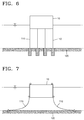
- FIGS. 5 through 7 illustrate an installation example of a mooring rope.
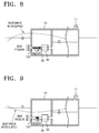
- FIGS. 8 and 9 illustrate the offshore floating power generator how flow of sea water is influenced by a waveform of a water surface.
- FIG. 10 is a schematic view of the offshore floating power generator including a flow velocity smoothing tank according to an exemplary embodiment.
- FIG. 11 is a schematic plan view of the offshore floating power generator of FIG. 10 .
- FIGS. 12 and 13 are schematic views illustrating the offshore floating power generator including an equilibrium water tank.
- FIGS. 14 and 15 are schematic views of the offshore floating power generator including a fender beam.
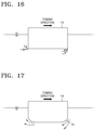
- FIG. 16 illustrates flow separation occurring when the sea water reservoir is drawn.
- FIG. 17 illustrates the offshore floating power generator when flow separation is reduced.
- FIG. 18 is a schematic view of a reinforcement wall inside the sea water reservoir.
- FIG. 19 is a schematic view of a buoyancy stabilizing room.
- FIG. 20 shows a cross-section and a front view of an inlet portion according to another exemplary embodiment.
- FIG. 21 shows a cross-section and a front view of an inlet portion according to another exemplary embodiment.
- the offshore floating power generator includes a sea water reservoir 10, an inlet pipe 20, a water turbine generator 30, and a water level adjustor.
- the sea water reservoir 10 stores sea water and floats on the sea surface.
- the sea water reservoir 10 ascends or descends from the sea surface according to the amount of sea water stored therein.
- the sea water reservoir 10 is provided to produce power by using a water level difference between the sea surface and a water level in the sea water reservoir 10.
- an outer wall of the sea water reservoir 10 is formed of concrete. More preferably, in order to prevent cracks in concrete due to tensile force, the outer wall of the sea water reservoir 10 may be formed of prestressed concrete (PC) that prevents cracks by maintaining a constant compressive force in a concrete portion of the outer wall by installing Tendon that is inserted into a concrete wall body.
- PC prestressed concrete
- water power generation is performed by using a water level difference between the open sea and the sea water reservoir 10.
- a water level difference is to be secured.
- a buoyancy structure is sunk deeper as a weight thereof per bottom area increases, thereby forming a greater water level difference.
- the sea water reservoir 10 is formed of a steel material, the weight thereof per unit area is too small and a water level difference may also be small.
- a water level difference may be easily provided when the sea water reservoir 10 is a concrete structure.
- sea water reservoir 10 by using a concrete structure is advantageous in terms of maintenance. Since sea water flows into and out of the sea water reservoir 10, the sea water reservoir 10 needs to be protected from corroding. If the sea water reservoir 10 is formed of a steel material, an outer wall and inner portions of the sea water reservoir 10 have to be regularly coated with protected coating to prevent corrosion, and if a structure size is large, it is as a matter of fact impossible to pull up the structure to land. Thus, the sea water reservoir 10 formed of concrete according to the exemplary embodiment of the inventive concept does not require protection coating, thereby increasing a usage period thereof and easiness in terms of maintenance.
- a long natural period of oscillation of the structure is set so that the sea water reservoir 10 stably floats on the sea surface.
- a buoyancy structure flowing on the sea surface not only has to endure wave power but also prevent resonance due to waves. If the buoyancy structure resonates, the amplitude of vertical movement of the buoyancy structure increases abruptly so that tensile force acting upon a mooring rope 110 also abruptly increases, resulting in damages to a connection portion between the mooring rope 110 and the buoyancy structure or detachment of the mooring rope 110 from the ocean floor 120.
- a resonance period of the buoyancy structure increases when a mass of the buoyancy structure increases, and thus, the sea water reservoir 10 formed of concrete may have a longer natural period of oscillations than that formed of a steel material.
- a machine room accommodating the inlet pipe 20 and the water turbine generator 30 or the like is included in the sea water reservoir 10, and the machine room may be entered through an entrance passage.
- transportation equipment 200 transporting people or cargo is installed in the entrance passage.
- an air vent 11, through which the atmospheric pressure may act upon a water level of the sea water reservoir 10, is mounted in the sea water reservoir 10.
- the inlet pipe 20 guides sea water flowing through an inlet portion 140, into the sea water reservoir 10.
- the inlet portion 140 is a portion through which sea water flows from the outside, and is disposed at a lateral lower end of the sea water reservoir 10 according to the present exemplary embodiment. According to the present exemplary embodiment, the inlet portion 140 protrudes from the sea water reservoir 10 as illustrated in FIG. 3 . In addition, slits 141 that are circumferentially spaced apart from one another are formed in the inlet portion 140.
- the slits 141 may have a width reducing from the outer side towards the inner side. An area over which sea water flows through the slit 141 is larger than a cross-section of the inlet pipe 20. That is, a total area of outermost widths of the slit 141 is greater than the cross-section of the inlet pipe 20.
- the inlet portion 140 may also not protrude from the outer wall of the sea water reservoir 10, as illustrated in, for example, FIGS. 1 , 8, and 9 .
- FIG. 20A is a cross-sectional view of the inlet portion 140 according to another exemplary embodiment
- FIG. 20B is a front view of the inlet portion 140 of FIG. 20A .
- the inlet portion 140 may not protrude from the outer wall of the sea water reservoir 10 but may be formed such that a plurality of slits 141 are formed as illustrated in FIG. 20B so that sea water may flow therethrough.
- FIG. 21A is a cross-sectional view of the inlet portion 140 according to another exemplary embodiment
- FIG. 21B is a front view of the inlet portion 140 of FIG. 21A
- the inlet portion 140 may protrude and extend in a radial direction from the outer wall of the sea water reservoir 10, and a plurality of slits 141 may be formed therein, as illustrated in FIG. 21 B , so that sea water flows therethrough.
- the water turbine generator 30 is provided to generate water power based on a water level difference, and is provided on the inlet pipe 20.
- the structure of the water turbine generator 30 is well known in the art, and thus detailed description thereof is omitted.
- the water level adjustor is provided in order to discharge sea water stored in the sea water reservoir 10 to the outside.
- a function of the water level adjustor is performed by using the water turbine generator 30.
- the water turbine generator 30 according to the present exemplary embodiment functions as a power generator when sea water enters, and functions as a pump to discharge the sea water from the sea water reservoir 10 to the outside.
- the water turbine generator 30 is a so-called reversible water turbine generator, performing the functions of both a power generator and a pump.
- the water level adjusting function may also be performed using an additional pump.
- sea water is discharged to the open sea by using the water level adjustor, and a water level in the sea water reservoir 10 becomes lower than a water level outside the sea water reservoir 10, so that, while a water level difference is generated, sea water flows into the sea water reservoir 10, and power is generated by using the water turbine generator 30.
- a first valve 40 and a second valve 50 are provided on the inlet pipe 20.
- the first valve 40 is disposed between the inlet portion 140 and the water turbine generator 30, and the second valve 50 is disposed between the water turbine generator 30 and the sea water reservoir 10.
- a screen 100 filtering out foreign substances is provided between the first valve 40 and the water turbine generator 30.
- a discharge pipe 60, through which sea water stored in the sea water reservoir 10, is discharged is branched off from the inlet pipe 20. As illustrated in FIGS. 1 and 2 , an end portion of the discharge pipe 60 extends through an upper portion of the sea water reservoir 10, and sea water is discharged through the discharge pipe 60.
- the sea water of the sea water reservoir 10 is pumped by using power generated using at least one of wind power, sunlight, and tidal power generating units, which will be described later, or by using power drawn from land.
- the water turbine generator 30 functions as a pump, and the pumped sea water is discharged to the open sea through the discharge pipe 60. While the sea water is being discharged, a water level of the sea water reservoir 10 is gradually reduced, and the sea water reservoir 10 on the whole is gradually moved up.
- a lowermost limit of the sea water reservoir 10 is an internal limit low-water level, and the level of the open sea seen from the sea water reservoir 10 becomes an external water level at the internal limit low-water level due to the sea water reservoir 10 that has been moved up.
- pumping is stopped.
- the first valve 40 and the second valve 50 are opened so that sea water naturally flows into the sea water reservoir 10 through the inlet portion 140, and power is generated here by using the water turbine generator 30.
- a power generating unit including the water turbine generator 30 is connected to a main transformer 190 provided on the sea water reservoir 10, and the main transformer 190 is connected to a substation on the shore through a submarine cable 180 so as to transmit generated power to the substation.
- the submarine cable 180 includes a communication line, a power transmission line, and a line for power that is used to drive internal elements in a power station and is drawn from land.
- FIGS. 5 through 7 illustrate the mooring rope 110 connected to the sea water reservoir 10 in various manners.
- FIG. 5 illustrates an example where the mooring rope 110 connects an upper portion of the sea water reservoir 10 to the ocean floor 120.
- FIG. 6 illustrates an example where an end of the mooring rope 110 is firmly fixed to the ocean floor 120.
- FIG. 7 illustrates an example where the mooring rope 110 is disposed closely to an outer wall of the sea water reservoir 10 to extend downwards.
- the mooring rope 110 may be installed in various manners.
- a length of the mooring rope 110 is adjustable according to the amount that the sea water reservoir 10 is sunk under sea level. A sufficient length of the mooring rope 110 should be secured such that the sea water reservoir 10 may ascend and descend by itself.
- the sea water reservoir 10 may float (horizontal motion or rotational motion) due to tidal currents or due to collision with a ship or a drifting structure and hamper stability of the submarine cable 180 buried underwater.
- the length of the mooring rope 110 is to be adjusted appropriately.
- the length of the mooring rope 110 may be configured to be automatically adjusted by, for example, measuring a water level in the sea water reservoir 10 by using an automatic water level measuring device to measure a depth at which the sea water reservoir 10 is sunk and by using a winch system.
- the automatic water level measuring device may use various methods such as a method of installing a buoy on the surface of water, a method of measuring a height of the surface of water by radiating an ultrasonic wave to the surface of water, or a method of measuring electric resistance of a conductor sunken underwater.
- the offshore floating power generator includes a wind power generating unit 70, a sunlight power generating unit 80, and a tidal power generating unit 90.
- the wind power generating unit 70 or the sunlight power generating unit 80 may be provided on the sea water reservoir 10, and the tidal power generating unit 90 may be provided under the sea water reservoir 10.
- the wind power generating unit 70, the sunlight power generating unit 80, and the tidal power generating unit 90 may be selectively installed or all of them may be installed.
- the wind power generating unit 70, the sunlight power generating unit 80, and the tidal power generating unit 90 are well known in the art, and thus description thereof is omitted.
- the wind power, sunlight, and tidal power generating units 70, 80, and 90 transmit generated power to land so that the power is available for use, and moreover, the power may also be used as power for driving internal elements of a power plant to pump the sea water of the sea water reservoir 10 to the open sea so as to set a standby state for water-power generation.
- the offshore floating power generator includes a flow velocity smoothing tank 130, an equilibrium water tank 160, a fender beam 170, a round portion 15, a buoyancy stabilization room 220, and a reinforcement wall 16.
- the flow velocity smoothing tank 130 is provided to prevent interruption of water power generation due to back flow of sea water caused by a change in a wave pressure when sea water enters through the inlet portion 140.
- FIG. 8 illustrates the offshore floating power generator at a wave crest where a waveform of the water surface curves upwards. As illustrated in FIG. 8 , at the wave crest, wave pressure is exerted into the sea water reservoir 10 so that a flow speed of sea water into the inlet pipe 20 may be abruptly increased.
- FIG. 9 illustrates the offshore floating power generator at a ridge of a wave where a waveform of the water surface curves downwards.
- wave pressure is exerted away from the sea water reservoir 10 so that a flow speed of sea water through the inlet pipe 20 is reduced.
- the flow velocity smoothing tank 130 is provided to minimize a change in a flow velocity of sea water flowing into the sea water reservoir 10 regardless of the ridge of a wave.
- FIG. 10 schematically illustrates sea water flowing through the inlet portion 140 and passing through the flow velocity smoothing tank 130 into the inlet pipe 20.
- An air vent 12 is mounted in the flow velocity smoothing tank 130 so that atmospheric pressure acts upon a water level of the flow velocity smoothing tank 130.
- the inlet pipe 20 when the flow velocity smoothing tank 130 is mounted, includes a first inlet pipe 21 and a second inlet pipe 22, as illustrated in FIG. 11 .
- the first inlet pipe 21 connects the inlet portion 140 and the flow velocity smoothing tank 130 to each other.
- the second inlet pipe 22 connects the flow velocity smoothing tank 130 and the sea water reservoir 10 to each other.
- the screen 100, the first valve 40, and a third valve 150 are provided on the first inlet pipe 21.
- the screen 100 is provided to filter out foreign substances contained in sea water.
- the first valve 40 is provided between the inlet portion 140 and the screen 100.
- the third valve 150 is provided between the screen 100 and the flow velocity smoothing tank 130.
- a fourth valve 210, the discharge pipe 60, the water turbine generator 30, and the second valve 50 are provided on the second inlet pipe 22.
- the fourth valve 210 is provided between the flow velocity smoothing tank 130 and the water turbine generator 30.
- the second valve 50 is provided between the water turbine generator 30 and the sea water reservoir 10.
- the first through fourth valves 40, 50, 150, and 210 operate as follows as sea water is discharged or enters.
- the fourth valve 210 When pumping sea water of the sea water reservoir 10 to the open sea, the fourth valve 210 is closed and the second valve 50 is opened. In this state, sea water is pumped out to the open sea through the discharge pipe 60 by using the water turbine generator 30.
- the sea water of the sea water reservoir 10 When the sea water of the sea water reservoir 10 is sufficiently pumped to the open sea so that a standby state allowing water power generation is set, only the first valve 40 is closed but the other valves are opened.
- the equilibrium water tank 160 is included to maintain a horizontality of the sea water reservoir 10. As illustrated in FIGS. 12 and 13 , the equilibrium water tank 160 is symmetrically provided at each edge of the sea water reservoir 10. According to the present exemplary embodiment, the equilibrium water tank 160 is provided at each corner of the sea water reservoir 10. Air vents 13 and 14 are formed in the equilibrium water tank 160 so that atmospheric pressure may act upon a water level of the equilibrium water tank 160.
- the equilibrium water tank 160 supplements the function of maintaining equilibrium of the sea water reservoir 10 by using the mooring rope 110.
- a change in a weight of an edge portion of a floating structure that is relatively far from a center thereof greatly affects an inclination of the floating structure.
- the equilibrium water tank 160 is symmetrically mounted at the edges of the sea water reservoir 10 so that the sea water reservoir 10 may sensitively react to adjustment of an inclination thereof.
- the fender beams 170 are provided to mitigate an impact with respect to a ship or other drifting structures. As illustrated in FIGS. 14 and 15 , according to the present exemplary embodiment, the fender beams 170 are provided along a lateral circumference of the sea water reservoir 10. The mooring rope 110 extends downwards between the fender beams 170.
- the sea water reservoir 10 includes the round portion 15 at each edge of a bottom surface thereof in order to get rid of flow separation.
- the offshore floating power generator according to the present inventive concept may be towed to a long distance sea or to a foreign country.
- a drag that affects a towing force and a towing speed is to be reduced.
- the drag is increased because a negative pressure is formed due to flow separation formed at corners of a bottom surface of the sea water reservoir 10 as illustrated in FIG. 16 .
- flow separation may be gotten rid of, thereby minimizing drag during towing.
- the reinforcement wall 16 is provided to increase structural stability of the sea water reservoir 10.
- the sea water reservoir 10 is used when the offshore floating power generator has a very great width, length, and height, and thus a plurality of reinforcement walls 16 are installed in the sea water reservoir 10 to provide structural stability thereof.
- the reinforcement walls 16 are arranged at uniform intervals in a lattice form when referring to FIG. 18 , but this is exemplary, and an arrangement of the reinforcement walls 16 may be modified in various manners as long as structural reinforcement of the sea water reservoir 10 and circulation of sea water therein are easily provided.
- the buoyancy stabilizing room 220 is provided to prevent the sea water reservoir 10 from sinking.
- An inner portion of the buoyancy stabilizing room 220 is formed of a steel material, and an outer portion of the buoyancy stabilizing room 220 is formed of concrete, and the buoyancy stabilizing room 220 is filled with air.
- the buoyancy stabilizing room 220 is provided on the sea water reservoir 10.
- the buoyancy stabilizing room 220 may be manufacture by using a hybrid concrete construction method in which a steel sheet is placed such that water tightness is maintained, and then concrete is deposited on an outer circumference of the steel sheet.
- the buoyancy stabilizing room 220 is filled with air.
- a location of the buoyancy stabilizing room 220 is not limited to the above.
- the buoyancy stabilizing room 220 may be accommodated inside the sea water reservoir 10 and disposed above a water level of sea water filled in the sea water reservoir 10, or may be disposed on a sidewall of the sea water reservoir 10.
- the offshore floating power generator of the present inventive concept power is generated by using a water level difference between the sea water reservoir 10 and the open sea.
- a time when to generate power, and an amount of power to be generated and a duration of power generation may be accurately predicted, thereby producing quality power.
- the offshore floating power generator may be used as an alternative in the case where it is difficult to install a power generator on land.
- the offshore floating power generator may be manufactured at a location where it is easy to manufacture the same, and then towed, and thus may be transported to a long distance, for example, to a foreign country.
- the sea water reservoir 10 does not disturb circulation of tidal currents or sea water compared to a structure fixed on the ocean floor 120, and is thus environment-friendly, and does not cause sedimentation or erosion of the ocean floor and thus does not cause geographical changes. While a fixed structure consumes more material and equipment at a deeper depth of water, the sea water reservoir 10 is a floating type, and is thus installed regardless of a change in a water depth, and thus is cost-effective in terms of construction costs.
- the sea water reservoir 10 may be manufactured on land or in a column water region and then transported by floating and then moored on a site.
- the manufacture of the sea water reservoir 10 is less influenced by sea weather such as typhoons or hurricanes than a fixed-type structure, and is thus constructed faster.
- the sea water reservoir 10 is towable over a far distance, and thus is highly mobile and is also easily applicable to a sea area where a difference between the ebb and flow of the tides is great.
- the offshore floating power generator according to the present inventive concept generates power by using renewable energies such as wind power, sunlight, and tidal force together, and thus, the renewable energies which are likely change greatly may be converted to power of a uniform output.
- power generated by driving the wind power, sunlight, and tidal power generating units 70, 80, and 90 may be transported to land for use or the power may be used as power for driving internal elements of a power plant so as to use the same as a power for pumping sea water of the sea water reservoir 10 to the open sea to thereby build a power standby state, and when a demand of power abruptly increases or if power is wished, the power may be generated through water power generation.
- the sea water reservoir 10 is automatically descended while a water level of the sea water reservoir 10 is increased as sea water enters the sea water reservoir 10, and thus, a variation in a difference in water levels during power generation is small so that quality power having uniform output may be intensively produced at a desired time.
- power is generated by using a water level difference between a water level in a sea water reservoir and sea level, so that quality power is provided at a required time, and when, how much, and how long power is to be generated may be accurately predicted.
- a wind power generating unit or a sunlight power generating unit is provided on the sea water reservoir, and a tidal power generating unit may be provided under the sea water reservoir, thereby transmitting power produced using the generating units to land or using the power as power for driving internal elements of a power plant to adjust the water level so as to intensively produce quality power and supply the power to land.
Landscapes
- Engineering & Computer Science (AREA)
- Mechanical Engineering (AREA)
- Chemical & Material Sciences (AREA)
- Combustion & Propulsion (AREA)
- General Engineering & Computer Science (AREA)
- Life Sciences & Earth Sciences (AREA)
- Power Engineering (AREA)
- Sustainable Development (AREA)
- Sustainable Energy (AREA)
- Oceanography (AREA)
- General Life Sciences & Earth Sciences (AREA)
- Other Liquid Machine Or Engine Such As Wave Power Use (AREA)
- Wind Motors (AREA)
Applications Claiming Priority (1)
| Application Number | Priority Date | Filing Date | Title |
|---|---|---|---|
| KR1020150058262A KR101642948B1 (ko) | 2015-04-24 | 2015-04-24 | 해상 부유식 발전장치 |
Publications (2)
| Publication Number | Publication Date |
|---|---|
| EP3085951A1 true EP3085951A1 (de) | 2016-10-26 |
| EP3085951B1 EP3085951B1 (de) | 2018-08-01 |
Family
ID=55745619
Family Applications (1)
| Application Number | Title | Priority Date | Filing Date |
|---|---|---|---|
| EP16164702.9A Active EP3085951B1 (de) | 2015-04-24 | 2016-04-11 | Schwimmender offshore-stromgenerator |
Country Status (3)
| Country | Link |
|---|---|
| EP (1) | EP3085951B1 (de) |
| KR (1) | KR101642948B1 (de) |
| CN (1) | CN106065843B (de) |
Cited By (3)
| Publication number | Priority date | Publication date | Assignee | Title |
|---|---|---|---|---|
| US11802537B2 (en) | 2018-08-13 | 2023-10-31 | International Business Machines Corporation | Methods and systems for wave energy generation prediction and optimization |
| US12459608B2 (en) | 2019-02-06 | 2025-11-04 | Xfloat Ltd. | Controlled floating solar module |
| EP4636988A3 (de) * | 2019-10-07 | 2026-01-14 | Lone Gull Holdings, Ltd. | Reservoirregulierende digitale laststeuerung |
Families Citing this family (5)
| Publication number | Priority date | Publication date | Assignee | Title |
|---|---|---|---|---|
| NO20161600A1 (no) * | 2016-10-06 | 2018-04-09 | Hydroelectric Corp Eiric Skaaren | Generering av strøm via en flytende offshore enhet |
| CN109398619A (zh) * | 2018-11-26 | 2019-03-01 | 南通航运职业技术学院 | 一种航道监测自蓄能航标 |
| KR102287189B1 (ko) * | 2020-07-16 | 2021-08-06 | 한국에너지기술연구원 | 에너지 발전 및 저장 시스템 |
| KR102375024B1 (ko) * | 2020-11-25 | 2022-03-17 | 한국전력공사 | 파력 펌프 보조형 해수 양수발전 시스템 |
| FR3166934A1 (fr) * | 2024-09-27 | 2026-04-03 | Nantes Universite | Système de production et d’inversion d’énergie en milieu marin |
Citations (7)
| Publication number | Priority date | Publication date | Assignee | Title |
|---|---|---|---|---|
| FR716038A (fr) * | 1931-04-25 | 1931-12-14 | Turbine en eau morte | |
| US4141670A (en) * | 1976-06-09 | 1979-02-27 | The Secretary of State for Energy, in Her Britannic Majesty's Government of the United Kindgom of Great Britain and Northern Ireland | Device for extracting energy from water waves |
| DE2843675A1 (de) * | 1978-10-06 | 1980-04-10 | Rainer Ing Grad Grueb | Vorrichtung zur stromerzeugung mittels von hydrostatischen druckes in einem gewaesser |
| EP2418375A1 (de) * | 2010-08-10 | 2012-02-15 | Wilhelm Ebrecht | Vorrichtung und Verfahren zum Speichern elektrischer Energie |
| US20120056430A1 (en) * | 2010-01-19 | 2012-03-08 | Janne Aaltonen | Generating hydroenergy |
| WO2013163979A2 (de) * | 2012-05-01 | 2013-11-07 | Siegfried Sumser | Off-shore-pumpspeicher-kraftwerk |
| DE102013015082A1 (de) * | 2013-09-08 | 2015-03-12 | Siegfried Sumser | Archimedischer Speicherpark |
Family Cites Families (6)
| Publication number | Priority date | Publication date | Assignee | Title |
|---|---|---|---|---|
| JPH0324499A (ja) * | 1989-06-22 | 1991-02-01 | Sumitomo Metal Mining Co Ltd | 放射性廃ガス中ルテニウムの除去方法 |
| JP2004052646A (ja) * | 2002-07-19 | 2004-02-19 | Tetsuji Tatsuoka | 沈水式発電装置 |
| JP2012088685A (ja) | 2010-09-22 | 2012-05-10 | Panasonic Corp | カメラ装置 |
| JP5688764B2 (ja) * | 2011-03-16 | 2015-03-25 | 大洋プラント株式会社 | 水上発電装置 |
| CN202560434U (zh) * | 2012-04-16 | 2012-11-28 | 缑清贺 | 一种带有防水涌管道的平冲水阻式水轮发电机 |
| JP6164976B2 (ja) * | 2013-08-13 | 2017-07-19 | 協立電機株式会社 | 越波式波力発電装置 |
-
2015
- 2015-04-24 KR KR1020150058262A patent/KR101642948B1/ko active Active
-
2016
- 2016-04-11 EP EP16164702.9A patent/EP3085951B1/de active Active
- 2016-04-18 CN CN201610239580.9A patent/CN106065843B/zh active Active
Patent Citations (7)
| Publication number | Priority date | Publication date | Assignee | Title |
|---|---|---|---|---|
| FR716038A (fr) * | 1931-04-25 | 1931-12-14 | Turbine en eau morte | |
| US4141670A (en) * | 1976-06-09 | 1979-02-27 | The Secretary of State for Energy, in Her Britannic Majesty's Government of the United Kindgom of Great Britain and Northern Ireland | Device for extracting energy from water waves |
| DE2843675A1 (de) * | 1978-10-06 | 1980-04-10 | Rainer Ing Grad Grueb | Vorrichtung zur stromerzeugung mittels von hydrostatischen druckes in einem gewaesser |
| US20120056430A1 (en) * | 2010-01-19 | 2012-03-08 | Janne Aaltonen | Generating hydroenergy |
| EP2418375A1 (de) * | 2010-08-10 | 2012-02-15 | Wilhelm Ebrecht | Vorrichtung und Verfahren zum Speichern elektrischer Energie |
| WO2013163979A2 (de) * | 2012-05-01 | 2013-11-07 | Siegfried Sumser | Off-shore-pumpspeicher-kraftwerk |
| DE102013015082A1 (de) * | 2013-09-08 | 2015-03-12 | Siegfried Sumser | Archimedischer Speicherpark |
Cited By (3)
| Publication number | Priority date | Publication date | Assignee | Title |
|---|---|---|---|---|
| US11802537B2 (en) | 2018-08-13 | 2023-10-31 | International Business Machines Corporation | Methods and systems for wave energy generation prediction and optimization |
| US12459608B2 (en) | 2019-02-06 | 2025-11-04 | Xfloat Ltd. | Controlled floating solar module |
| EP4636988A3 (de) * | 2019-10-07 | 2026-01-14 | Lone Gull Holdings, Ltd. | Reservoirregulierende digitale laststeuerung |
Also Published As
| Publication number | Publication date |
|---|---|
| CN106065843A (zh) | 2016-11-02 |
| CN106065843B (zh) | 2019-01-01 |
| EP3085951B1 (de) | 2018-08-01 |
| KR101642948B1 (ko) | 2016-07-26 |
Similar Documents
| Publication | Publication Date | Title |
|---|---|---|
| EP3085951B1 (de) | Schwimmender offshore-stromgenerator | |
| EP3085950B1 (de) | Schwimmender offshore-stromgenerator | |
| US10774813B2 (en) | Floating structure and method of installing same | |
| EP2604501B1 (de) | System und Verankerung und Anlagen von schwimmenden Windturbinentürmen und entsprechende Verfahren zum Anlegen und Ausstellen davon | |
| US20180170488A1 (en) | Floating structure for wind turbine and method of intalling same | |
| US11203398B2 (en) | Buoy and installation method for the buoy | |
| CN102506012A (zh) | 锚泊半潜连体底座海上风力发电机组 | |
| CA2755864A1 (en) | Floating platform for wind energy extraction | |
| KR101554872B1 (ko) | 부유식 방파제 | |
| KR20130098586A (ko) | 부유식 태양광 발전장치 | |
| KR20090067387A (ko) | 심해 반잠수식 가두리 양식방법 및 그 장치 | |
| KR101606398B1 (ko) | 마이크로 버블을 이용한 수질 개선장치 | |
| JP2017141799A (ja) | 発電システム | |
| KR102429989B1 (ko) | 앵커부재를 구비한 수중 에너지 저장구조물 및 그 시공방법 | |
| KR101936696B1 (ko) | 해상 부유식 선박형 조류발전장치 | |
| KR101431520B1 (ko) | 부상형 풍력 발전장치 |
Legal Events
| Date | Code | Title | Description |
|---|---|---|---|
| PUAI | Public reference made under article 153(3) epc to a published international application that has entered the european phase |
Free format text: ORIGINAL CODE: 0009012 |
|
| 17P | Request for examination filed |
Effective date: 20160411 |
|
| AK | Designated contracting states |
Kind code of ref document: A1 Designated state(s): AL AT BE BG CH CY CZ DE DK EE ES FI FR GB GR HR HU IE IS IT LI LT LU LV MC MK MT NL NO PL PT RO RS SE SI SK SM TR |
|
| AX | Request for extension of the european patent |
Extension state: BA ME |
|
| GRAP | Despatch of communication of intention to grant a patent |
Free format text: ORIGINAL CODE: EPIDOSNIGR1 |
|
| STAA | Information on the status of an ep patent application or granted ep patent |
Free format text: STATUS: GRANT OF PATENT IS INTENDED |
|
| INTG | Intention to grant announced |
Effective date: 20180514 |
|
| GRAS | Grant fee paid |
Free format text: ORIGINAL CODE: EPIDOSNIGR3 |
|
| GRAA | (expected) grant |
Free format text: ORIGINAL CODE: 0009210 |
|
| STAA | Information on the status of an ep patent application or granted ep patent |
Free format text: STATUS: THE PATENT HAS BEEN GRANTED |
|
| AK | Designated contracting states |
Kind code of ref document: B1 Designated state(s): AL AT BE BG CH CY CZ DE DK EE ES FI FR GB GR HR HU IE IS IT LI LT LU LV MC MK MT NL NO PL PT RO RS SE SI SK SM TR |
|
| REG | Reference to a national code |
Ref country code: GB Ref legal event code: FG4D |
|
| REG | Reference to a national code |
Ref country code: CH Ref legal event code: EP Ref country code: AT Ref legal event code: REF Ref document number: 1024603 Country of ref document: AT Kind code of ref document: T Effective date: 20180815 |
|
| REG | Reference to a national code |
Ref country code: IE Ref legal event code: FG4D |
|
| REG | Reference to a national code |
Ref country code: DE Ref legal event code: R096 Ref document number: 602016004387 Country of ref document: DE |
|
| REG | Reference to a national code |
Ref country code: NL Ref legal event code: MP Effective date: 20180801 |
|
| REG | Reference to a national code |
Ref country code: LT Ref legal event code: MG4D |
|
| REG | Reference to a national code |
Ref country code: AT Ref legal event code: MK05 Ref document number: 1024603 Country of ref document: AT Kind code of ref document: T Effective date: 20180801 |
|
| PG25 | Lapsed in a contracting state [announced via postgrant information from national office to epo] |
Ref country code: FI Free format text: LAPSE BECAUSE OF FAILURE TO SUBMIT A TRANSLATION OF THE DESCRIPTION OR TO PAY THE FEE WITHIN THE PRESCRIBED TIME-LIMIT Effective date: 20180801 Ref country code: GR Free format text: LAPSE BECAUSE OF FAILURE TO SUBMIT A TRANSLATION OF THE DESCRIPTION OR TO PAY THE FEE WITHIN THE PRESCRIBED TIME-LIMIT Effective date: 20181102 Ref country code: NO Free format text: LAPSE BECAUSE OF FAILURE TO SUBMIT A TRANSLATION OF THE DESCRIPTION OR TO PAY THE FEE WITHIN THE PRESCRIBED TIME-LIMIT Effective date: 20181101 Ref country code: AT Free format text: LAPSE BECAUSE OF FAILURE TO SUBMIT A TRANSLATION OF THE DESCRIPTION OR TO PAY THE FEE WITHIN THE PRESCRIBED TIME-LIMIT Effective date: 20180801 Ref country code: IS Free format text: LAPSE BECAUSE OF FAILURE TO SUBMIT A TRANSLATION OF THE DESCRIPTION OR TO PAY THE FEE WITHIN THE PRESCRIBED TIME-LIMIT Effective date: 20181201 Ref country code: RS Free format text: LAPSE BECAUSE OF FAILURE TO SUBMIT A TRANSLATION OF THE DESCRIPTION OR TO PAY THE FEE WITHIN THE PRESCRIBED TIME-LIMIT Effective date: 20180801 Ref country code: SE Free format text: LAPSE BECAUSE OF FAILURE TO SUBMIT A TRANSLATION OF THE DESCRIPTION OR TO PAY THE FEE WITHIN THE PRESCRIBED TIME-LIMIT Effective date: 20180801 Ref country code: BG Free format text: LAPSE BECAUSE OF FAILURE TO SUBMIT A TRANSLATION OF THE DESCRIPTION OR TO PAY THE FEE WITHIN THE PRESCRIBED TIME-LIMIT Effective date: 20181101 Ref country code: NL Free format text: LAPSE BECAUSE OF FAILURE TO SUBMIT A TRANSLATION OF THE DESCRIPTION OR TO PAY THE FEE WITHIN THE PRESCRIBED TIME-LIMIT Effective date: 20180801 Ref country code: LT Free format text: LAPSE BECAUSE OF FAILURE TO SUBMIT A TRANSLATION OF THE DESCRIPTION OR TO PAY THE FEE WITHIN THE PRESCRIBED TIME-LIMIT Effective date: 20180801 Ref country code: PL Free format text: LAPSE BECAUSE OF FAILURE TO SUBMIT A TRANSLATION OF THE DESCRIPTION OR TO PAY THE FEE WITHIN THE PRESCRIBED TIME-LIMIT Effective date: 20180801 |
|
| PG25 | Lapsed in a contracting state [announced via postgrant information from national office to epo] |
Ref country code: AL Free format text: LAPSE BECAUSE OF FAILURE TO SUBMIT A TRANSLATION OF THE DESCRIPTION OR TO PAY THE FEE WITHIN THE PRESCRIBED TIME-LIMIT Effective date: 20180801 Ref country code: HR Free format text: LAPSE BECAUSE OF FAILURE TO SUBMIT A TRANSLATION OF THE DESCRIPTION OR TO PAY THE FEE WITHIN THE PRESCRIBED TIME-LIMIT Effective date: 20180801 Ref country code: LV Free format text: LAPSE BECAUSE OF FAILURE TO SUBMIT A TRANSLATION OF THE DESCRIPTION OR TO PAY THE FEE WITHIN THE PRESCRIBED TIME-LIMIT Effective date: 20180801 |
|
| PG25 | Lapsed in a contracting state [announced via postgrant information from national office to epo] |
Ref country code: ES Free format text: LAPSE BECAUSE OF FAILURE TO SUBMIT A TRANSLATION OF THE DESCRIPTION OR TO PAY THE FEE WITHIN THE PRESCRIBED TIME-LIMIT Effective date: 20180801 Ref country code: RO Free format text: LAPSE BECAUSE OF FAILURE TO SUBMIT A TRANSLATION OF THE DESCRIPTION OR TO PAY THE FEE WITHIN THE PRESCRIBED TIME-LIMIT Effective date: 20180801 Ref country code: IT Free format text: LAPSE BECAUSE OF FAILURE TO SUBMIT A TRANSLATION OF THE DESCRIPTION OR TO PAY THE FEE WITHIN THE PRESCRIBED TIME-LIMIT Effective date: 20180801 Ref country code: CZ Free format text: LAPSE BECAUSE OF FAILURE TO SUBMIT A TRANSLATION OF THE DESCRIPTION OR TO PAY THE FEE WITHIN THE PRESCRIBED TIME-LIMIT Effective date: 20180801 Ref country code: EE Free format text: LAPSE BECAUSE OF FAILURE TO SUBMIT A TRANSLATION OF THE DESCRIPTION OR TO PAY THE FEE WITHIN THE PRESCRIBED TIME-LIMIT Effective date: 20180801 |
|
| REG | Reference to a national code |
Ref country code: DE Ref legal event code: R097 Ref document number: 602016004387 Country of ref document: DE |
|
| PG25 | Lapsed in a contracting state [announced via postgrant information from national office to epo] |
Ref country code: SM Free format text: LAPSE BECAUSE OF FAILURE TO SUBMIT A TRANSLATION OF THE DESCRIPTION OR TO PAY THE FEE WITHIN THE PRESCRIBED TIME-LIMIT Effective date: 20180801 Ref country code: DK Free format text: LAPSE BECAUSE OF FAILURE TO SUBMIT A TRANSLATION OF THE DESCRIPTION OR TO PAY THE FEE WITHIN THE PRESCRIBED TIME-LIMIT Effective date: 20180801 Ref country code: SK Free format text: LAPSE BECAUSE OF FAILURE TO SUBMIT A TRANSLATION OF THE DESCRIPTION OR TO PAY THE FEE WITHIN THE PRESCRIBED TIME-LIMIT Effective date: 20180801 |
|
| PLBE | No opposition filed within time limit |
Free format text: ORIGINAL CODE: 0009261 |
|
| STAA | Information on the status of an ep patent application or granted ep patent |
Free format text: STATUS: NO OPPOSITION FILED WITHIN TIME LIMIT |
|
| 26N | No opposition filed |
Effective date: 20190503 |
|
| PG25 | Lapsed in a contracting state [announced via postgrant information from national office to epo] |
Ref country code: SI Free format text: LAPSE BECAUSE OF FAILURE TO SUBMIT A TRANSLATION OF THE DESCRIPTION OR TO PAY THE FEE WITHIN THE PRESCRIBED TIME-LIMIT Effective date: 20180801 |
|
| REG | Reference to a national code |
Ref country code: DE Ref legal event code: R119 Ref document number: 602016004387 Country of ref document: DE |
|
| REG | Reference to a national code |
Ref country code: CH Ref legal event code: PL |
|
| REG | Reference to a national code |
Ref country code: BE Ref legal event code: MM Effective date: 20190430 |
|
| PG25 | Lapsed in a contracting state [announced via postgrant information from national office to epo] |
Ref country code: LU Free format text: LAPSE BECAUSE OF NON-PAYMENT OF DUE FEES Effective date: 20190411 Ref country code: MC Free format text: LAPSE BECAUSE OF FAILURE TO SUBMIT A TRANSLATION OF THE DESCRIPTION OR TO PAY THE FEE WITHIN THE PRESCRIBED TIME-LIMIT Effective date: 20180801 |
|
| PG25 | Lapsed in a contracting state [announced via postgrant information from national office to epo] |
Ref country code: LI Free format text: LAPSE BECAUSE OF NON-PAYMENT OF DUE FEES Effective date: 20190430 Ref country code: CH Free format text: LAPSE BECAUSE OF NON-PAYMENT OF DUE FEES Effective date: 20190430 Ref country code: DE Free format text: LAPSE BECAUSE OF NON-PAYMENT OF DUE FEES Effective date: 20191101 |
|
| PG25 | Lapsed in a contracting state [announced via postgrant information from national office to epo] |
Ref country code: BE Free format text: LAPSE BECAUSE OF NON-PAYMENT OF DUE FEES Effective date: 20190430 Ref country code: FR Free format text: LAPSE BECAUSE OF NON-PAYMENT OF DUE FEES Effective date: 20190430 |
|
| PG25 | Lapsed in a contracting state [announced via postgrant information from national office to epo] |
Ref country code: TR Free format text: LAPSE BECAUSE OF FAILURE TO SUBMIT A TRANSLATION OF THE DESCRIPTION OR TO PAY THE FEE WITHIN THE PRESCRIBED TIME-LIMIT Effective date: 20180801 |
|
| PG25 | Lapsed in a contracting state [announced via postgrant information from national office to epo] |
Ref country code: IE Free format text: LAPSE BECAUSE OF NON-PAYMENT OF DUE FEES Effective date: 20190411 |
|
| PG25 | Lapsed in a contracting state [announced via postgrant information from national office to epo] |
Ref country code: PT Free format text: LAPSE BECAUSE OF FAILURE TO SUBMIT A TRANSLATION OF THE DESCRIPTION OR TO PAY THE FEE WITHIN THE PRESCRIBED TIME-LIMIT Effective date: 20181201 |
|
| PG25 | Lapsed in a contracting state [announced via postgrant information from national office to epo] |
Ref country code: CY Free format text: LAPSE BECAUSE OF FAILURE TO SUBMIT A TRANSLATION OF THE DESCRIPTION OR TO PAY THE FEE WITHIN THE PRESCRIBED TIME-LIMIT Effective date: 20180801 |
|
| PG25 | Lapsed in a contracting state [announced via postgrant information from national office to epo] |
Ref country code: HU Free format text: LAPSE BECAUSE OF FAILURE TO SUBMIT A TRANSLATION OF THE DESCRIPTION OR TO PAY THE FEE WITHIN THE PRESCRIBED TIME-LIMIT; INVALID AB INITIO Effective date: 20160411 Ref country code: MT Free format text: LAPSE BECAUSE OF FAILURE TO SUBMIT A TRANSLATION OF THE DESCRIPTION OR TO PAY THE FEE WITHIN THE PRESCRIBED TIME-LIMIT Effective date: 20180801 |
|
| PG25 | Lapsed in a contracting state [announced via postgrant information from national office to epo] |
Ref country code: MK Free format text: LAPSE BECAUSE OF FAILURE TO SUBMIT A TRANSLATION OF THE DESCRIPTION OR TO PAY THE FEE WITHIN THE PRESCRIBED TIME-LIMIT Effective date: 20180801 |
|
| PGFP | Annual fee paid to national office [announced via postgrant information from national office to epo] |
Ref country code: GB Payment date: 20260327 Year of fee payment: 11 |