EP3085954A1 - Unité de production d'énergie éolienne et système de production d'énergie éolienne empilé verticalement - Google Patents
Unité de production d'énergie éolienne et système de production d'énergie éolienne empilé verticalement Download PDFInfo
- Publication number
- EP3085954A1 EP3085954A1 EP13899835.6A EP13899835A EP3085954A1 EP 3085954 A1 EP3085954 A1 EP 3085954A1 EP 13899835 A EP13899835 A EP 13899835A EP 3085954 A1 EP3085954 A1 EP 3085954A1
- Authority
- EP
- European Patent Office
- Prior art keywords
- wind power
- power generation
- impellers
- upper plate
- lower plate
- Prior art date
- Legal status (The legal status is an assumption and is not a legal conclusion. Google has not performed a legal analysis and makes no representation as to the accuracy of the status listed.)
- Withdrawn
Links
- 238000010248 power generation Methods 0.000 title claims abstract description 50
- 230000005611 electricity Effects 0.000 claims abstract description 10
- 230000002093 peripheral effect Effects 0.000 claims description 4
- 238000005452 bending Methods 0.000 claims description 3
- 230000003068 static effect Effects 0.000 description 5
- 238000002474 experimental method Methods 0.000 description 4
- 230000005540 biological transmission Effects 0.000 description 2
- 238000006243 chemical reaction Methods 0.000 description 2
- 230000007423 decrease Effects 0.000 description 2
- 230000003247 decreasing effect Effects 0.000 description 2
- 238000010586 diagram Methods 0.000 description 2
- 238000009434 installation Methods 0.000 description 2
- 239000002356 single layer Substances 0.000 description 2
- 230000000052 comparative effect Effects 0.000 description 1
- 230000032798 delamination Effects 0.000 description 1
- 230000000694 effects Effects 0.000 description 1
- 230000005674 electromagnetic induction Effects 0.000 description 1
- 230000004907 flux Effects 0.000 description 1
- 239000002803 fossil fuel Substances 0.000 description 1
- 230000010354 integration Effects 0.000 description 1
- 238000000034 method Methods 0.000 description 1
- 238000010792 warming Methods 0.000 description 1
Images


Classifications
-
- F—MECHANICAL ENGINEERING; LIGHTING; HEATING; WEAPONS; BLASTING
- F03—MACHINES OR ENGINES FOR LIQUIDS; WIND, SPRING, OR WEIGHT MOTORS; PRODUCING MECHANICAL POWER OR A REACTIVE PROPULSIVE THRUST, NOT OTHERWISE PROVIDED FOR
- F03D—WIND MOTORS
- F03D9/00—Adaptations of wind motors for special use; Combinations of wind motors with apparatus driven thereby; Wind motors specially adapted for installation in particular locations
- F03D9/20—Wind motors characterised by the driven apparatus
- F03D9/25—Wind motors characterised by the driven apparatus the apparatus being an electrical generator
-
- F—MECHANICAL ENGINEERING; LIGHTING; HEATING; WEAPONS; BLASTING
- F03—MACHINES OR ENGINES FOR LIQUIDS; WIND, SPRING, OR WEIGHT MOTORS; PRODUCING MECHANICAL POWER OR A REACTIVE PROPULSIVE THRUST, NOT OTHERWISE PROVIDED FOR
- F03D—WIND MOTORS
- F03D3/00—Wind motors with rotation axis substantially perpendicular to the air flow entering the rotor
- F03D3/005—Wind motors with rotation axis substantially perpendicular to the air flow entering the rotor the axis being vertical
-
- F—MECHANICAL ENGINEERING; LIGHTING; HEATING; WEAPONS; BLASTING
- F03—MACHINES OR ENGINES FOR LIQUIDS; WIND, SPRING, OR WEIGHT MOTORS; PRODUCING MECHANICAL POWER OR A REACTIVE PROPULSIVE THRUST, NOT OTHERWISE PROVIDED FOR
- F03D—WIND MOTORS
- F03D3/00—Wind motors with rotation axis substantially perpendicular to the air flow entering the rotor
- F03D3/02—Wind motors with rotation axis substantially perpendicular to the air flow entering the rotor having a plurality of rotors
-
- F—MECHANICAL ENGINEERING; LIGHTING; HEATING; WEAPONS; BLASTING
- F03—MACHINES OR ENGINES FOR LIQUIDS; WIND, SPRING, OR WEIGHT MOTORS; PRODUCING MECHANICAL POWER OR A REACTIVE PROPULSIVE THRUST, NOT OTHERWISE PROVIDED FOR
- F03D—WIND MOTORS
- F03D3/00—Wind motors with rotation axis substantially perpendicular to the air flow entering the rotor
- F03D3/04—Wind motors with rotation axis substantially perpendicular to the air flow entering the rotor having stationary wind-guiding means, e.g. with shrouds or channels
- F03D3/0409—Wind motors with rotation axis substantially perpendicular to the air flow entering the rotor having stationary wind-guiding means, e.g. with shrouds or channels surrounding the rotor
-
- F—MECHANICAL ENGINEERING; LIGHTING; HEATING; WEAPONS; BLASTING
- F03—MACHINES OR ENGINES FOR LIQUIDS; WIND, SPRING, OR WEIGHT MOTORS; PRODUCING MECHANICAL POWER OR A REACTIVE PROPULSIVE THRUST, NOT OTHERWISE PROVIDED FOR
- F03D—WIND MOTORS
- F03D3/00—Wind motors with rotation axis substantially perpendicular to the air flow entering the rotor
- F03D3/04—Wind motors with rotation axis substantially perpendicular to the air flow entering the rotor having stationary wind-guiding means, e.g. with shrouds or channels
- F03D3/0427—Wind motors with rotation axis substantially perpendicular to the air flow entering the rotor having stationary wind-guiding means, e.g. with shrouds or channels with converging inlets, i.e. the guiding means intercepting an area greater than the effective rotor area
-
- F—MECHANICAL ENGINEERING; LIGHTING; HEATING; WEAPONS; BLASTING
- F03—MACHINES OR ENGINES FOR LIQUIDS; WIND, SPRING, OR WEIGHT MOTORS; PRODUCING MECHANICAL POWER OR A REACTIVE PROPULSIVE THRUST, NOT OTHERWISE PROVIDED FOR
- F03D—WIND MOTORS
- F03D9/00—Adaptations of wind motors for special use; Combinations of wind motors with apparatus driven thereby; Wind motors specially adapted for installation in particular locations
- F03D9/30—Wind motors specially adapted for installation in particular locations
- F03D9/34—Wind motors specially adapted for installation in particular locations on stationary objects or on stationary man-made structures
-
- F—MECHANICAL ENGINEERING; LIGHTING; HEATING; WEAPONS; BLASTING
- F05—INDEXING SCHEMES RELATING TO ENGINES OR PUMPS IN VARIOUS SUBCLASSES OF CLASSES F01-F04
- F05B—INDEXING SCHEME RELATING TO WIND, SPRING, WEIGHT, INERTIA OR LIKE MOTORS, TO MACHINES OR ENGINES FOR LIQUIDS COVERED BY SUBCLASSES F03B, F03D AND F03G
- F05B2240/00—Components
- F05B2240/90—Mounting on supporting structures or systems
- F05B2240/91—Mounting on supporting structures or systems on a stationary structure
- F05B2240/911—Mounting on supporting structures or systems on a stationary structure already existing for a prior purpose
- F05B2240/9112—Mounting on supporting structures or systems on a stationary structure already existing for a prior purpose which is a building
-
- Y—GENERAL TAGGING OF NEW TECHNOLOGICAL DEVELOPMENTS; GENERAL TAGGING OF CROSS-SECTIONAL TECHNOLOGIES SPANNING OVER SEVERAL SECTIONS OF THE IPC; TECHNICAL SUBJECTS COVERED BY FORMER USPC CROSS-REFERENCE ART COLLECTIONS [XRACs] AND DIGESTS
- Y02—TECHNOLOGIES OR APPLICATIONS FOR MITIGATION OR ADAPTATION AGAINST CLIMATE CHANGE
- Y02B—CLIMATE CHANGE MITIGATION TECHNOLOGIES RELATED TO BUILDINGS, e.g. HOUSING, HOUSE APPLIANCES OR RELATED END-USER APPLICATIONS
- Y02B10/00—Integration of renewable energy sources in buildings
- Y02B10/30—Wind power
-
- Y—GENERAL TAGGING OF NEW TECHNOLOGICAL DEVELOPMENTS; GENERAL TAGGING OF CROSS-SECTIONAL TECHNOLOGIES SPANNING OVER SEVERAL SECTIONS OF THE IPC; TECHNICAL SUBJECTS COVERED BY FORMER USPC CROSS-REFERENCE ART COLLECTIONS [XRACs] AND DIGESTS
- Y02—TECHNOLOGIES OR APPLICATIONS FOR MITIGATION OR ADAPTATION AGAINST CLIMATE CHANGE
- Y02E—REDUCTION OF GREENHOUSE GAS [GHG] EMISSIONS, RELATED TO ENERGY GENERATION, TRANSMISSION OR DISTRIBUTION
- Y02E10/00—Energy generation through renewable energy sources
- Y02E10/70—Wind energy
- Y02E10/728—Onshore wind turbines
-
- Y—GENERAL TAGGING OF NEW TECHNOLOGICAL DEVELOPMENTS; GENERAL TAGGING OF CROSS-SECTIONAL TECHNOLOGIES SPANNING OVER SEVERAL SECTIONS OF THE IPC; TECHNICAL SUBJECTS COVERED BY FORMER USPC CROSS-REFERENCE ART COLLECTIONS [XRACs] AND DIGESTS
- Y02—TECHNOLOGIES OR APPLICATIONS FOR MITIGATION OR ADAPTATION AGAINST CLIMATE CHANGE
- Y02E—REDUCTION OF GREENHOUSE GAS [GHG] EMISSIONS, RELATED TO ENERGY GENERATION, TRANSMISSION OR DISTRIBUTION
- Y02E10/00—Energy generation through renewable energy sources
- Y02E10/70—Wind energy
- Y02E10/74—Wind turbines with rotation axis perpendicular to the wind direction
Definitions
- the present invention relates to a wind power generation unit and a vertically stacked wind power generation system.
- the wind energy has attracted attention.
- the wind energy has a problem that a density is low and the direction and the speed of wind frequently change. Further, continuity of wind is low.
- the operation rate of the existing axial-flow wind turbines currently used is as low as 30% or less.
- An object of the present invention is to provide a wind power generation unit and a vertically stacked wind power generation system capable of increasing the overall generator efficiency by improving at least one or more of wind direction, wind speed, and continuity of wind.
- a wind power generation unit including: a housing including an upper plate and a lower plate; impellers arranged to be rotatable between the upper plate and the lower plate and rotated by a flow of air introduced between the upper plate and the lower plate; and a generator interlocked with rotation of the impellers and configured to generate electricity according to the rotation of the impellers.
- the housing may further include fences arranged between the upper plate and the lower plate and extended from outer peripheral portions of the upper plate and the lower plate toward the impellers.
- the wind power generation unit may further include guide vanes respectively positioned between the fences and the impellers and bent in an opposite direction to a bending direction of blades of the impellers.
- the impellers, the guide vanes, and the fences may be provided in multiple, and a circle formed by the multiple impellers, a circle formed by the multiple guide vanes, and a circle formed by the multiple fences may be in a concentric relationship with one another.
- the number of the guide vanes may be 24.
- a gap between the guide vane and the impeller may be 0.15 m.
- the impellers may be of a cross-flow type.
- the wind power generation unit may further include guide vanes arranged between the upper plate and the lower plate and bent and extended from outer peripheral portions of the upper plate and the lower plate toward the impellers.
- a vertically stacked wind power generation system including: a driving unit configured to generate rotatory power by a flow of air; and a generator configured to receive the rotatory power from the driving unit and generate electricity
- the driving unit includes: a housing including an upper plate and a lower plate forming an inner space; and impellers arranged to be rotatable within the inner space and configured to generate the rotatory power by a flow of air introduced into the inner space, the housing includes multiple inner spaces stacked along a direction from the lower plate toward the upper plate, and the impellers may be provided in multiple to be respectively arranged within the multiple inner spaces.
- wind power generation unit and vertically stacked wind power generation system can increase the overall generator efficiency by improving at least one or more of wind direction, wind speed, and continuity of wind.
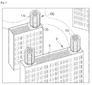
- FIG. 1 is a perspective view illustrating an installation state of a vertically stacked wind power generation system 100 according to an exemplary embodiment of the present invention.
- the vertically stacked wind power generation system 100 may include a driving unit 110, a generator 130, and an adjunct 150.
- the driving unit 110 is configured to receive wind and generate rotatory power.
- the driving unit 110 may be formed into a single layer, or may be stacked so as to be formed into multiple layers as described in the present exemplary embodiment.
- the generator 130 is configured to receive the rotatory power generated by the driving unit 110 and generate electricity.
- the generator 130 may be positioned under the driving unit 110.
- the adjunct 150 is installed at an available space on an upper surface of the driving unit 110, and may be, for example, a solar cell module.
- the vertically stacked wind power generation system 100 can be installed at an unused space in a downtown area, such as a rooftop R of a building B. Otherwise, the vertically stacked wind power generation system 100 can be installed at an open portion on a middle floor of the building B. Since strong wind blows between buildings due to the high-rise buildings B, such a position may be effective for the vertically stacked wind power generation system 100 in generating electricity. Further, the vertically stacked wind power generation system 100 can be installed at a barge so as to be positioned on the sea as well as the building B on land.
- the driving unit 110 is formed into multiple layers. Therefore, driving efficiency of the driving unit 110 is not much decreased by a change in amount of wind depending on a height of the rooftop R. Therefore, it is possible to improve continuity of wind and thus possible to increase generator efficiency as compared with a wind power generator simply relying on a single propeller only.
- the solar cell module it is possible to generate electricity caused by wind power and also possible to generate electricity caused by sunlight at the same time.
- a wind power generation unit 200 used in the vertically stacked wind power generation system 100 will be explained with reference to FIG. 2 and FIG. 3 .
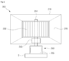
- FIG. 2 is a conceptual diagram illustrating a configuration of a wind power generation unit 200 constituting a part of the vertically stacked wind power generation system 100 of FIG. 1
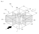
- FIG. 3 is a perspective view illustrating a configuration of the wind power generation unit 200 of FIG. 2 in detail except a generator 250.
- the wind power generation unit 200 includes a single layer of the driving unit 110 and the generator 130 of the vertically stacked wind power generation system 100.
- the wind power generation unit 200 may include a housing 210, an impeller 230, a generator 250, and a guide vane 270.
- the housing 210 is configured to form an inner space I where the impeller 230 and the guide vane 270 are positioned.
- the housing 210 may include an upper plate 211, a lower plate 213, and a fence 215.
- Each of the upper plate 211 and the lower plate 213 is formed into a plate shape, and may have a square shape ( FIG. 3 ), an octagonal shape ( FIG. 1 ), or the like.
- the upper plate 211 and the lower plate 213 may have shapes corresponding to each other and are arranged to be spaced from each other in a height direction.
- the fence 215 may be arranged to be perpendicular to the upper plate 211 and the lower plate 213.
- a height of the fence 215 may be a distance between the upper plate 211 and the lower plate 213.
- the fence 215 may be provided in multiple and the multiple fences 215 may be arranged to head toward the centers of the upper plate 211 and the lower plate 213 from edge portions thereof, respectively.
- the impeller 230 is positioned to be rotatable within the inner space I, and configured to be rotated by force of air introduced into the inner space I and generate rotatory power.
- the impeller 230 may be positioned at a central area of the inner space I.
- a central axis of rotation of the impeller 230 may be provided along a direction from the lower plate 213 toward the upper plate 211.
- a blade 235 of the impeller 230 may be provided in multiple.
- the generator 250 is configured to be connected to the impeller 230 and generate electricity by the rotatory power generated by the impeller 230.
- the generator 250 may include a shaft 251, a transmission 253, and a generating unit 255.
- the shaft 251 is a rod connected to the rotation center of the impeller 230.
- the transmission 253 connects the shaft 251 to the generating unit 255.
- the generating unit 255 includes a coil therein and generates currents on the coil by electromagnetic induction while the shaft 251 is rotated.
- the generating unit 255 can be supported by a supporting table S.
- the generating unit 250 is on the whole the same as the generator 130 of the vertically stacked wind power generation system 100, but it is a part of the wind power generation unit 200 and thus denoted by reference numeral 250.
- the guide vane 270 is configured to accelerate and guide air introduced into the inner space I toward the impeller 230.
- the guide vane 270 may be fixed at a position between the fence 215 and the impeller 230.
- the guide vane 270 includes multiple blades 275, and some of the blades 275 corresponding to the fences 215 may be connected to the fences 215.
- a circle formed by the multiple blades 275 may be positioned between a circle formed by the multiple fences 215 and a circle formed by the multiple blades 235 so as to be in a concentric relationship with one another.
- the fence 215 (further, the guide vane 270) has a width W2 greater than a width W1 of the impeller 230, and, thus, can introduce air in a greater amount toward the impeller 230 as compared with a case where the impeller 230 itself is present. This provides an advantage that a flux of air toward the impeller 230 is increased.
- FIG. 4 is a plane view illustrating an impeller 230 and a guide vane 270 of FIG. 3 .
- the blades 275 of the guide vane 270 are bent in the same direction as the blades 235 of the impeller 230 in the opposite form to that of FIG. 3 .
- the impeller 230 is of a cross-flow type.
- air is introduced into the blades 235 on one side and discharged from the blades 235 on the opposite side.
- Such an impeller of a cross-flow type has an energy conversion efficiency of 35% or more, and, thus, is efficient as compared with an impeller of an axial-flow type having an energy conversion efficiency of 20%.
- a shape of the blade 235 is determined by its inlet angle ⁇ and its outlet angle ⁇ .
- the inlet angle ⁇ is an angle between a tangent line of a circle connecting the outer sides of the blades 235 and an outward extension line of the blade 235.
- the outlet angle ⁇ is an angle between a tangent line of a circle connecting the inner sides of the blades 235 and an inward extension line of the blade 235.
- the guide vane 270 may include the blades 275 in the number corresponding to the number of the blades 235 of the impeller 230.
- air flowing between a pair of the adjacent blades 275 of the guide vane 270 is further accelerated and thus can be introduced between a pair of the corresponding blades 235 of the impeller 230.
- a gap C between the blade 275 of the guide vane 270 and the blade 235 of the impeller 230 can be determined in order to maximize rotatory power of the impeller 230. This will be explained with reference to FIG. 10 and FIG. 11.
- FIG. 5 is a transversal cross-sectional view illustrating a configuration of a wind power generation unit 300 according to another exemplary embodiment of the present invention.
- the wind power generation unit 300 may include a housing 310, an impeller 330, a generator (refer to 250 in FIG. 2 ), and a guide vane 370.
- a first vane 371 is an integration of the fence 215 of the housing 210 and the guide vane 270 in the above-described exemplary embodiment.
- the first vane 371 is bent and extended from an edge portion of the housing 310.
- the first vane 371 deflects an angle of air flow from the edge portion of the housing 310.
- the first vane 371 is bent in an opposite direction to a bending direction of the impeller 330 and provides drag to the impeller 330.
- the guide vane 370 may include a second vane 375 positioned between the first vanes 371. Air introduced between the first vanes 371 is more precisely guided to the second vane 375 than to the impeller 330.
- FIG. 6 provides images showing results of comparative experiments on a static pressure distribution depending on the number of blades of an impeller.
- the maximum static pressure increases only until the number of the blades 235 of the impeller 230 is 24. In other words, if the number of the blades 235 of the impeller 230 is 30, the maximum static pressure decreases. Therefore, when the number of the blades 235 of the impeller 230 is 24, the optimum efficiency can be achieved.
- a speed of inflow air is 10 m/s
- a revolution per minute of the impeller 230 is 20, and the outlet angle ⁇ of the blade 235 of the impeller 230 is 85°.
- the number of the blades 235 of the impeller 230 is 16, and the gap C is 0.1 m, 0.15 m, 0.2 m, or 0.5 m.
- wind power generation unit and the vertically tacked wind power generation system described above are not limited to the configurations and the operation methods explained in the above exemplary embodiments.
- the above exemplary embodiments can be selectively combined in whole or in part so as to be modified in various ways.
Landscapes
- Engineering & Computer Science (AREA)
- Life Sciences & Earth Sciences (AREA)
- Sustainable Development (AREA)
- Sustainable Energy (AREA)
- Chemical & Material Sciences (AREA)
- Combustion & Propulsion (AREA)
- Mechanical Engineering (AREA)
- General Engineering & Computer Science (AREA)
- Power Engineering (AREA)
- Wind Motors (AREA)
Applications Claiming Priority (1)
| Application Number | Priority Date | Filing Date | Title |
|---|---|---|---|
| PCT/KR2013/011718 WO2015093641A1 (fr) | 2013-12-17 | 2013-12-17 | Unité de production d'énergie éolienne et système de production d'énergie éolienne empilé verticalement |
Publications (1)
| Publication Number | Publication Date |
|---|---|
| EP3085954A1 true EP3085954A1 (fr) | 2016-10-26 |
Family
ID=53367849
Family Applications (1)
| Application Number | Title | Priority Date | Filing Date |
|---|---|---|---|
| EP13899835.6A Withdrawn EP3085954A1 (fr) | 2013-12-17 | 2013-12-17 | Unité de production d'énergie éolienne et système de production d'énergie éolienne empilé verticalement |
Country Status (4)
| Country | Link |
|---|---|
| US (1) | US20150167635A1 (fr) |
| EP (1) | EP3085954A1 (fr) |
| CN (1) | CN105431631A (fr) |
| WO (1) | WO2015093641A1 (fr) |
Families Citing this family (6)
| Publication number | Priority date | Publication date | Assignee | Title |
|---|---|---|---|---|
| US20180266390A1 (en) * | 2013-03-14 | 2018-09-20 | Hover Energy, LLC | Wind power generating rotor with diffuser or diverter system for a wind turbine |
| GR1008967B (el) * | 2015-11-11 | 2017-02-28 | Ιωαννης Ελευθεριου Δροσης | Κιονας ανεμογεννητρια |
| CN111677626B (zh) * | 2020-06-03 | 2022-02-25 | 河南恒聚新能源设备有限公司 | 垂直轴涡轮风力发电系统 |
| CN116057273B (zh) * | 2020-08-10 | 2026-06-02 | 速度风力涡轮机有限责任公司 | 性能增强的可配置多用途横流风力涡轮机 |
| USD1013896S1 (en) * | 2021-12-02 | 2024-02-06 | Gerhard Wieser | Wind turbine tower |
| CN117627869A (zh) * | 2022-08-18 | 2024-03-01 | 北京理工大学 | 一种翼型阵列式超结构气流集中装置和风力发电设备 |
Family Cites Families (20)
| Publication number | Priority date | Publication date | Assignee | Title |
|---|---|---|---|---|
| US1463924A (en) * | 1922-05-03 | 1923-08-07 | Ozaki Yukiteru | Wind turbine |
| US1645855A (en) * | 1926-07-06 | 1927-10-18 | Vore Ernest E De | Wind motor |
| ES454192A1 (es) * | 1976-12-13 | 1977-12-01 | Zapata Martinez Valentin | Sistema para la obtencion y regulacion de energia a partir de corrientes aereas, maritimas o fluviales. |
| US4551631A (en) * | 1984-07-06 | 1985-11-05 | Trigilio Gaetano T | Wind and solar electric generating plant |
| US4834610A (en) * | 1986-04-25 | 1989-05-30 | Bond Iii Frederick W | Wind processing air turbine, and methods of constructing and utilizing same |
| US6015258A (en) * | 1998-04-17 | 2000-01-18 | Taylor; Ronald J. | Wind turbine |
| US6448669B1 (en) * | 1998-12-01 | 2002-09-10 | Dillyn M. Elder | Water power generation system |
| US6870280B2 (en) * | 2002-05-08 | 2005-03-22 | Elcho R. Pechler | Vertical-axis wind turbine |
| WO2007010551A2 (fr) * | 2005-03-22 | 2007-01-25 | Vinod Kumar Chamanlal Kariya | Eolienne a axe vertical comprenant des dispositifs de guidage |
| US7633177B2 (en) * | 2005-04-14 | 2009-12-15 | Natural Forces, Llc | Reduced friction wind turbine apparatus and method |
| US7329965B2 (en) * | 2005-06-03 | 2008-02-12 | Novastron Corporation | Aerodynamic-hybrid vertical-axis wind turbine |
| CN201377383Y (zh) * | 2007-11-28 | 2010-01-06 | 李业权 | 漩涡式导风板风车 |
| US7969036B2 (en) * | 2008-05-22 | 2011-06-28 | Chun-Neng Chung | Apparatus for generating electric power using wind energy |
| IT1396927B1 (it) * | 2009-11-13 | 2012-12-20 | Alfonsi | Turbina ad elevate prestazioni, particolarmente a potenza specifica incrementata. |
| TW201031820A (en) * | 2009-12-04 | 2010-09-01 | Fung Gin Da Energy Science & Technology Co Ltd | Wind collection type wind power generator |
| ES2556654T3 (es) * | 2010-08-26 | 2016-01-19 | Guy Andrew Vaz | Turbina de eje vertical |
| KR101063775B1 (ko) * | 2011-04-28 | 2011-09-19 | 주식회사지티에너지 | 다목적 회전장치와 이를 구비한 발전시스템 |
| CN103195654A (zh) * | 2012-01-04 | 2013-07-10 | 陈宏基 | 风能动力装置 |
| CN202991349U (zh) * | 2012-07-27 | 2013-06-12 | 刘先知 | 一种电动车用风能发电装置 |
| US9121384B2 (en) * | 2013-06-24 | 2015-09-01 | Chun-Shuan Lin | Vertical axis wind turbine |
-
2013
- 2013-12-17 WO PCT/KR2013/011718 patent/WO2015093641A1/fr not_active Ceased
- 2013-12-17 EP EP13899835.6A patent/EP3085954A1/fr not_active Withdrawn
- 2013-12-17 CN CN201380076639.1A patent/CN105431631A/zh active Pending
-
2014
- 2014-12-16 US US14/572,065 patent/US20150167635A1/en not_active Abandoned
Also Published As
| Publication number | Publication date |
|---|---|
| CN105431631A (zh) | 2016-03-23 |
| US20150167635A1 (en) | 2015-06-18 |
| WO2015093641A1 (fr) | 2015-06-25 |
Similar Documents
| Publication | Publication Date | Title |
|---|---|---|
| US9041239B2 (en) | Vertical axis wind turbine with cambered airfoil blades | |
| EP1095216B1 (fr) | Eolienne | |
| US9683547B2 (en) | Wind turbine having nacelle fence | |
| US20150167635A1 (en) | Wind power generation unit and wind power generation system of vertically stacked type | |
| US9989033B2 (en) | Horizontal axis wind or water turbine with forked or multi-blade upper segments | |
| CN103930670B (zh) | 用于改进的水转子的系统和方法 | |
| CN105715454B (zh) | 全方位导流无轴风力发电装置 | |
| CN104340339A (zh) | 潮流发电装置及其安装框架 | |
| CN204877787U (zh) | 全方位导流无轴风力发电装置 | |
| KR101241134B1 (ko) | 조류발전장치 | |
| CN102325991A (zh) | 原动机 | |
| US20140064918A1 (en) | Device and system for harvesting the energy of a fluid stream | |
| EP2762719B1 (fr) | Turbine omnidirectionnelle à écoulement combiné | |
| KR20150070696A (ko) | 풍력 발전 유니트 및 수직 적층형 풍력 발전 시스템 | |
| JP2018040301A (ja) | 風水力発電装置 | |
| CN104061126A (zh) | 万向受风轴流式风力发电机 | |
| JP2019060237A (ja) | 風車システムまたはウィンドファーム | |
| CN105041564A (zh) | 一种垂直轴风力发电机风轮 | |
| US20140255160A1 (en) | Hydro Turbine | |
| CN103629045A (zh) | 一种h型垂直轴风力机叶轮的多系统组合结构 | |
| JP2015113775A (ja) | 垂直軸型風車 | |
| CN102588209B (zh) | 垂直轴风叶 | |
| KR101418674B1 (ko) | 루버유도형 풍력발전기 | |
| KR102825415B1 (ko) | 전방향 발전 장치 | |
| CN214944723U (zh) | 一种多路径导风的建筑外墙结构 |
Legal Events
| Date | Code | Title | Description |
|---|---|---|---|
| PUAI | Public reference made under article 153(3) epc to a published international application that has entered the european phase |
Free format text: ORIGINAL CODE: 0009012 |
|
| 17P | Request for examination filed |
Effective date: 20151214 |
|
| AK | Designated contracting states |
Kind code of ref document: A1 Designated state(s): AL AT BE BG CH CY CZ DE DK EE ES FI FR GB GR HR HU IE IS IT LI LT LU LV MC MK MT NL NO PL PT RO RS SE SI SK SM TR |
|
| AX | Request for extension of the european patent |
Extension state: BA ME |
|
| DAX | Request for extension of the european patent (deleted) | ||
| STAA | Information on the status of an ep patent application or granted ep patent |
Free format text: STATUS: THE APPLICATION IS DEEMED TO BE WITHDRAWN |
|
| 18D | Application deemed to be withdrawn |
Effective date: 20170701 |