EP3085974A1 - Verbindungsvorrichtung und anzeigebildschirm damit - Google Patents
Verbindungsvorrichtung und anzeigebildschirm damit Download PDFInfo
- Publication number
- EP3085974A1 EP3085974A1 EP15868627.9A EP15868627A EP3085974A1 EP 3085974 A1 EP3085974 A1 EP 3085974A1 EP 15868627 A EP15868627 A EP 15868627A EP 3085974 A1 EP3085974 A1 EP 3085974A1
- Authority
- EP
- European Patent Office
- Prior art keywords
- hole
- movable part
- locking
- state
- avoiding
- Prior art date
- Legal status (The legal status is an assumption and is not a legal conclusion. Google has not performed a legal analysis and makes no representation as to the accuracy of the status listed.)
- Granted
Links
Images


Classifications
-
- G—PHYSICS
- G09—EDUCATION; CRYPTOGRAPHY; DISPLAY; ADVERTISING; SEALS
- G09F—DISPLAYING; ADVERTISING; SIGNS; LABELS OR NAME-PLATES; SEALS
- G09F9/00—Indicating arrangements for variable information in which the information is built-up on a support by selection or combination of individual elements
- G09F9/30—Indicating arrangements for variable information in which the information is built-up on a support by selection or combination of individual elements in which the desired character or characters are formed by combining individual elements
- G09F9/302—Indicating arrangements for variable information in which the information is built-up on a support by selection or combination of individual elements in which the desired character or characters are formed by combining individual elements characterised by the form or geometrical disposition of the individual elements
- G09F9/3026—Video wall, i.e. stackable semiconductor matrix display modules
-
- F—MECHANICAL ENGINEERING; LIGHTING; HEATING; WEAPONS; BLASTING
- F16—ENGINEERING ELEMENTS AND UNITS; GENERAL MEASURES FOR PRODUCING AND MAINTAINING EFFECTIVE FUNCTIONING OF MACHINES OR INSTALLATIONS; THERMAL INSULATION IN GENERAL
- F16B—DEVICES FOR FASTENING OR SECURING CONSTRUCTIONAL ELEMENTS OR MACHINE PARTS TOGETHER, e.g. NAILS, BOLTS, CIRCLIPS, CLAMPS, CLIPS OR WEDGES; JOINTS OR JOINTING
- F16B13/00—Dowels or other devices fastened in walls or the like by inserting them in holes made therein for that purpose
- F16B13/04—Dowels or other devices fastened in walls or the like by inserting them in holes made therein for that purpose with parts gripping in the hole or behind the reverse side of the wall after inserting from the front
-
- F—MECHANICAL ENGINEERING; LIGHTING; HEATING; WEAPONS; BLASTING
- F16—ENGINEERING ELEMENTS AND UNITS; GENERAL MEASURES FOR PRODUCING AND MAINTAINING EFFECTIVE FUNCTIONING OF MACHINES OR INSTALLATIONS; THERMAL INSULATION IN GENERAL
- F16B—DEVICES FOR FASTENING OR SECURING CONSTRUCTIONAL ELEMENTS OR MACHINE PARTS TOGETHER, e.g. NAILS, BOLTS, CIRCLIPS, CLAMPS, CLIPS OR WEDGES; JOINTS OR JOINTING
- F16B19/00—Bolts without screw-thread; Pins, including deformable elements; Rivets
- F16B19/02—Bolts or sleeves for positioning of machine parts, e.g. notched taper pins, fitting pins, sleeves, eccentric positioning rings
-
- F—MECHANICAL ENGINEERING; LIGHTING; HEATING; WEAPONS; BLASTING
- F16—ENGINEERING ELEMENTS AND UNITS; GENERAL MEASURES FOR PRODUCING AND MAINTAINING EFFECTIVE FUNCTIONING OF MACHINES OR INSTALLATIONS; THERMAL INSULATION IN GENERAL
- F16B—DEVICES FOR FASTENING OR SECURING CONSTRUCTIONAL ELEMENTS OR MACHINE PARTS TOGETHER, e.g. NAILS, BOLTS, CIRCLIPS, CLAMPS, CLIPS OR WEDGES; JOINTS OR JOINTING
- F16B21/00—Means for preventing relative axial movement of a pin, spigot, shaft or the like and a member surrounding it; Stud-and-socket releasable fastenings
- F16B21/09—Releasable fastening devices with a stud engaging a keyhole slot
-
- F—MECHANICAL ENGINEERING; LIGHTING; HEATING; WEAPONS; BLASTING
- F16—ENGINEERING ELEMENTS AND UNITS; GENERAL MEASURES FOR PRODUCING AND MAINTAINING EFFECTIVE FUNCTIONING OF MACHINES OR INSTALLATIONS; THERMAL INSULATION IN GENERAL
- F16B—DEVICES FOR FASTENING OR SECURING CONSTRUCTIONAL ELEMENTS OR MACHINE PARTS TOGETHER, e.g. NAILS, BOLTS, CIRCLIPS, CLAMPS, CLIPS OR WEDGES; JOINTS OR JOINTING
- F16B5/00—Joining sheets or plates, e.g. panels, to one another or to strips or bars parallel to them
- F16B5/0004—Joining sheets, plates or panels in abutting relationship
- F16B5/0084—Joining sheets, plates or panels in abutting relationship characterised by particular locking means
- F16B5/0088—Joining sheets, plates or panels in abutting relationship characterised by particular locking means with locking means moving substantially perpendicular to the main plane, e.g. pins, screws
-
- G—PHYSICS
- G02—OPTICS
- G02F—OPTICAL DEVICES OR ARRANGEMENTS FOR THE CONTROL OF LIGHT BY MODIFICATION OF THE OPTICAL PROPERTIES OF THE MEDIA OF THE ELEMENTS INVOLVED THEREIN; NON-LINEAR OPTICS; FREQUENCY-CHANGING OF LIGHT; OPTICAL LOGIC ELEMENTS; OPTICAL ANALOGUE/DIGITAL CONVERTERS
- G02F1/00—Devices or arrangements for the control of the intensity, colour, phase, polarisation or direction of light arriving from an independent light source, e.g. switching, gating or modulating; Non-linear optics
- G02F1/01—Devices or arrangements for the control of the intensity, colour, phase, polarisation or direction of light arriving from an independent light source, e.g. switching, gating or modulating; Non-linear optics for the control of the intensity, phase, polarisation or colour
- G02F1/13—Devices or arrangements for the control of the intensity, colour, phase, polarisation or direction of light arriving from an independent light source, e.g. switching, gating or modulating; Non-linear optics for the control of the intensity, phase, polarisation or colour based on liquid crystals, e.g. single liquid crystal display cells
- G02F1/133—Constructional arrangements; Operation of liquid crystal cells; Circuit arrangements
- G02F1/1333—Constructional arrangements; Manufacturing methods
- G02F1/13336—Combining plural substrates to produce large-area displays, e.g. tiled displays
-
- G—PHYSICS
- G06—COMPUTING OR CALCULATING; COUNTING
- G06F—ELECTRIC DIGITAL DATA PROCESSING
- G06F3/00—Input arrangements for transferring data to be processed into a form capable of being handled by the computer; Output arrangements for transferring data from processing unit to output unit, e.g. interface arrangements
- G06F3/14—Digital output to display device ; Cooperation and interconnection of the display device with other functional units
- G06F3/1423—Digital output to display device ; Cooperation and interconnection of the display device with other functional units controlling a plurality of local displays, e.g. CRT and flat panel display
- G06F3/1446—Digital output to display device ; Cooperation and interconnection of the display device with other functional units controlling a plurality of local displays, e.g. CRT and flat panel display display composed of modules, e.g. video walls
-
- Y—GENERAL TAGGING OF NEW TECHNOLOGICAL DEVELOPMENTS; GENERAL TAGGING OF CROSS-SECTIONAL TECHNOLOGIES SPANNING OVER SEVERAL SECTIONS OF THE IPC; TECHNICAL SUBJECTS COVERED BY FORMER USPC CROSS-REFERENCE ART COLLECTIONS [XRACs] AND DIGESTS
- Y10—TECHNICAL SUBJECTS COVERED BY FORMER USPC
- Y10T—TECHNICAL SUBJECTS COVERED BY FORMER US CLASSIFICATION
- Y10T403/00—Joints and connections
- Y10T403/59—Manually releaseable latch type
- Y10T403/599—Spring biased manipulator
Definitions
- the invention relates to the technical field of assembling, and in particular to a connecting device and a display screen with the same.
- a Light-Emitting Diode (LED) display screen may be mounted under coordination of multiple persons, and cooperation of more labor force is required by site mounting of a screen body, which causes waste of labor cost, economic cost, environmental protection resources and the like.
- LED Light-Emitting Diode
- the invention is intended to provide a connecting device and a display screen with the same, which reduce the amount of labor and improve mounting efficiency.
- a connecting device which comprises: a first connecting member, comprising a first fixed part, a first movable part provided in a manner of moving in a first direction and a first elastic part positioned between the first fixed part and the first movable part, the first fixed part being provided with a first component connecting part and the first movable part being provided with a mounting through hole which is through in a second direction perpendicular to the first direction; and a second connecting member matched with the first connecting member, provided with a second component connecting part and an accommodation groove for accommodating a hole wall of the mounting through hole, the second connecting member having an inward extension state of extending into the mounting through hole and an outward shifting state of shifting out of the mounting through hole, the first movable part having a connection state of causing the hole wall of the mounting through hole to extend into the accommodation groove and a separation state of causing the hole wall of the mounting through hole to extend out of the accommodation groove and the first movable part being in
- the second connecting member comprises a second fixed part and a second movable part provided on the second fixed part in the manner of moving in the second direction, the second component connecting part is formed on the second fixed part, the accommodation groove is formed in the second movable part, and the second movable part has the inward extension state and the outward shifting state.
- the accommodation groove is an annular groove
- the second fixed part is provided with a threaded hole which is through in the second direction
- the second movable part comprises a hanger rod
- the accommodation groove is formed in the hanger rod
- the hanger rod is provided with an external threaded section matched with the threaded hole.
- the mounting through hole comprises a penetration hole area and a locking hole area which are distributed in the first direction, an area of the locking hole area is smaller than an area of the penetration hole area, and when the first movable part is in the connection state, the second movable part is positioned in the locking hole area and a hole wall of the locking hole area extends into the accommodation groove; and when the first movable part is in the separation state, the second movable part is positioned in the penetration hole area.
- the first elastic part is a first compression spring.
- the second movable part further comprises a screwing handle fixedly connected with the hanger rod, the second fixed part is positioned between the screwing handle and the first connecting member, and multiple handholding grooves are formed in a circumferential direction of the screwing handle at intervals.
- both the first component connecting part and the second component connecting part are screw penetration through holes.
- a display screen which comprises: a first display unit profile with a first connecting part; and a second display unit profile with a second connecting part, the display screen further comprises: the abovementioned connecting device, the first fixed part is fixedly connected with the first connecting part, the second connecting member is fixedly connected with the second connecting part, the first connecting part is positioned between the second connecting part and a first movable part and the first connecting part is provided with a first avoiding through hole for avoiding the second connecting member.
- the first connecting member further comprises a locking device provided on the first movable part
- the locking device comprises a locking pin and a second elastic member
- an acting force of the second elastic member over the locking pin faces the second connecting part
- the first connecting part is provided with a second avoiding through hole for avoiding the locking pin
- a hole wall of the second avoiding through hole is provided with a sliding chute which allows the locking pin to move
- the sliding chute is positioned between the second avoiding through hole and the first avoiding through hole
- a chute bottom of the sliding chute is deviated from the second connecting part
- a pressing bump extending towards the second avoiding through hole is provided on the second connecting part
- the locking pin has a first locking state of extending into the second avoiding through hole and being stopped by the hole wall of the second avoiding through hole and a second locking state of contacting with the pressing bump to move into the sliding chute and being stopped by a chute wall of the sliding chute, and when the locking pin is in the first locking state, the first movable part is in a
- the first connecting part is provided with a guide groove extending in the second direction
- the first movable part is provided with a guided part extending into the guide groove.
- the first fixed part is fixedly connected with a first component
- the second connecting member is fixedly connected with a second component
- the second connecting member enters the inward extension state and the first movable part is only subjected to the action of the first elastic part, so that the first movable part is in the connection state under the acting force of the first elastic part, the hole wall of the mounting through hole extends into the accommodation groove at this moment, and the first component and the second component are fixed.
- the connecting device of the invention reduces the amount of labor and improves the mounting efficiency.
- a connecting device of the embodiment comprises a first connecting member 10 and a second connecting member 20 matched with the first connecting member 10.
- the first connecting member 10 comprises a first fixed part 11, a first movable part 12 provided in a manner of moving in a first direction and a first elastic part 13 positioned between the first fixed part 11 and the first movable part 12, the first fixed part 11 is provided with a first component connecting part 11 a, and the first movable part 12 is provided with a mounting through hole 14 which is through in a second direction perpendicular to the first direction.
- the second connecting member 20 is provided with a second component connecting part 20a and an accommodation groove 20b for accommodating a hole wall of the mounting through hole 14, the second connecting member 20 has an inward extension state of extending into the mounting through hole 14 and an outward shifting state of shifting out of the mounting through hole 14, the first movable part 12 has a connection state of causing the hole wall of the mounting through hole 14 to extend into the accommodation groove 20b and a separation state of causing the hole wall of the mounting through hole 14 to shift out of the accommodation groove 20b, and the first movable part 12 is in the connection state only under an action of the first elastic part 13.
- the first fixed part 11 is fixedly connected with a first component
- the second connecting member 20 is fixedly connected with a second component
- the second connecting member 20 enters the inward extension state and the first movable part 12 is only subjected to the action of the first elastic part 13, so that the first movable part 12 is in the connection state under acting force of the first elastic part 13, the hole wall of the mounting through hole 14 extends into the accommodation groove 20b at this moment, and the first component and the second component are fixed.
- the connecting device of the invention reduces the amount of labor and improves the mounting efficiency.
- the second connecting member 20 comprises a second fixed part 21 and a second movable part 22 provided on the second fixed part 21 in the manner of moving in the second direction, a second component connecting part 20a is formed on the second fixed part 21, the accommodation groove 20b is formed in the second movable part 22, and the second movable part 22 has the inward extension state and the outward shifting state.
- the second movable part 22 may move to connect the first component with the second component more firmly.
- the accommodation groove 20b is an annular groove
- the second fixed part 21 is provided with a threaded hole which is through in the second direction
- the second movable part 22 comprises a hanger rod 23
- the accommodation groove 20b is formed in the hanger rod 23
- the hanger rod is provided with an external threaded section matched with the threaded hole.
- the hanger rod 23 may be screwed to implement arrangement of the second movable part in the manner of moving in the second direction and achieve higher movement accuracy.
- the second movable part 22 is provided with a rack
- the second fixed part 21 is provided with a gear matched with the rack
- the gear may also be driven to rotate to implement arrangement of the second movable part 22 in the manner of moving in the second direction.
- the mounting through hole 14 comprises a penetration hole area 14a and a locking hole area 14b which are distributed in the first direction, an area of the locking hole area 14b is smaller than an area of the penetration hole area 14a, and when the first movable part 12 is in the connection state, the second movable part 22 is positioned in the locking hole area 14b and the hole wall of the locking hole area 14b extends into the accommodation groove 20b; and when the first movable part 12 is in the separation state, the second movable part 22 is positioned in the penetration hole area 14a.
- the first connecting member 10 and the second connecting member 20 may be connected more firmly.
- the first elastic part 13 is a first compression spring.
- the first elastic part 13 may also be a tension spring or an elastic sleeve.
- the second movable part 22 further comprises a screwing handle 24 fixedly connected with the hanger rod 23, the second fixed part 21 is positioned between the screwing handle 24 and the first connecting member 10, and multiple handholding grooves 24a are formed in a circumferential direction of the screwing handle 24 at intervals.
- the hanger rod 23 may be conveniently screwed.
- both the first component connecting part 11 a and the second component connecting part 20a are screw penetration through holes.
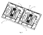
- the invention further provides a display screen, and as shown in Fig. 3 and Fig. 4 , the display screen of the embodiment comprises a first display unit profile 30, a second display unit profile 40 and the connecting device of the abovementioned embodiment.
- the first display unit profile 30 is provided with a first connecting part 31.
- the second display unit profile 40 is provided with a second connecting part 41.
- a first fixed part 11 is fixedly connected with the first connecting part 31
- a second fixed part 21 is fixedly connected with the second connecting part 41
- the first connecting part 31 is positioned between the second connecting part 41 and a first movable part 12, and the first connecting part 31 is provided with a first avoiding through hole 32 for avoiding a second movable part 22.
- the display screen of the embodiment reduces the amount of labor and improves mounting efficiency.
- a first connecting member 10 further comprises a locking device 15 provided on the first movable part 12, the locking device 15 comprises a locking pin 16 and a second elastic member 17, acting force of the second elastic member 17 over the locking pin 16 faces the second connecting part 41, the first connecting part 31 is provided with a second avoiding through hole 33 for avoiding the locking pin 16, a hole wall of the second avoiding through hole 33 is provided with a sliding chute 34 which allows the locking pin 16 to move, the sliding chute 34 is positioned between the second avoiding through hole 33 and the first avoiding through hole 32, a chute bottom of the sliding chute 34 is deviated from the second connecting part 41, a pressing bump 42 extending towards the second avoiding through hole 33 isprovided on the second connecting part 41, the locking pin 16 has a first locking state of extending into the second avoiding through hole 33 and being stopped by the hole wall of the second avoiding through hole 33 and a second locking state of contacting with the pressing bump 42 to move into the sliding chute 34
- the locking pin 16 is in the first locking state, the first movable part 12 is in the separation state, the first connecting part 31 and the second connecting part 41 move towards each other, the second movable part 22 penetrates through the first avoiding through hole 32 and extends into a penetration hole area 14a, the pressing bump 42 contacts with the locking pin 16 at the same time, and applies force for overcoming acting force of the second elastic member 17 to the locking pin 16, the locking pin 16 shifts out of the second avoiding through hole 33 and extends into the sliding chute 34 to finally enter the second locking state, and at this moment, the second movable part 22 is positioned in a locking hole area 14b and the first movable part 12 is in the connection state, so that the first display unit profile 30 is connected with the second display unit profile 40; and the second movable part 22 is screwed to stably connect the first display unit profile 30 with the second display unit profile 40.
- the first connecting part 31 is provided with a guide groove 35 extending in the second direction
- the first movable part 12 is provided with a guided part extending into the guide groove 35.
- the first movable part 12 may conveniently move according to a predetermined trajectory.
- the locking device 15 further comprises a handheld handle 18, and the handheld handle 18 is fixed on the first movable part 12 to conveniently drive the first movable part 12 to overcome elasticity of the first elastic part 13. As shown in Fig.
- the second connecting part 41 is positioned between the second fixed part 21 and the first connecting part 31 to avoid influence of the second fixed part 21 on seamless jointing of the second connecting part 41 and the first connecting part 31, and the second connecting part 41 is provided with a third avoiding through hole for avoiding the second movable part 22.
Landscapes
- Engineering & Computer Science (AREA)
- General Engineering & Computer Science (AREA)
- Mechanical Engineering (AREA)
- Physics & Mathematics (AREA)
- General Physics & Mathematics (AREA)
- Theoretical Computer Science (AREA)
- Multimedia (AREA)
- Nonlinear Science (AREA)
- Mathematical Physics (AREA)
- Chemical & Material Sciences (AREA)
- Crystallography & Structural Chemistry (AREA)
- Human Computer Interaction (AREA)
- Optics & Photonics (AREA)
- Devices For Indicating Variable Information By Combining Individual Elements (AREA)
- Connection Of Plates (AREA)
- Snaps, Bayonet Connections, Set Pins, And Snap Rings (AREA)
Applications Claiming Priority (2)
| Application Number | Priority Date | Filing Date | Title |
|---|---|---|---|
| CN201410770482.9A CN104482005B (zh) | 2014-12-12 | 2014-12-12 | 连接装置及具有其的显示屏 |
| PCT/CN2015/095062 WO2016091053A1 (zh) | 2014-12-12 | 2015-11-19 | 连接装置及具有其的显示屏 |
Publications (3)
| Publication Number | Publication Date |
|---|---|
| EP3085974A1 true EP3085974A1 (de) | 2016-10-26 |
| EP3085974A4 EP3085974A4 (de) | 2017-08-23 |
| EP3085974B1 EP3085974B1 (de) | 2020-04-08 |
Family
ID=52756584
Family Applications (1)
| Application Number | Title | Priority Date | Filing Date |
|---|---|---|---|
| EP15868627.9A Active EP3085974B1 (de) | 2014-12-12 | 2015-11-19 | Verbindungsvorrichtung und anzeigebildschirm damit |
Country Status (8)
| Country | Link |
|---|---|
| US (1) | US10520000B2 (de) |
| EP (1) | EP3085974B1 (de) |
| JP (1) | JP6398127B2 (de) |
| KR (1) | KR101871193B1 (de) |
| CN (1) | CN104482005B (de) |
| CA (1) | CA2938063C (de) |
| ES (1) | ES2791150T3 (de) |
| WO (1) | WO2016091053A1 (de) |
Cited By (1)
| Publication number | Priority date | Publication date | Assignee | Title |
|---|---|---|---|---|
| WO2021073396A1 (zh) * | 2019-10-16 | 2021-04-22 | 深圳市鸿合创新信息技术有限责任公司 | 用于拼接屏的拼接组件及拼接屏 |
Families Citing this family (11)
| Publication number | Priority date | Publication date | Assignee | Title |
|---|---|---|---|---|
| CN104482005B (zh) | 2014-12-12 | 2017-08-15 | 深圳利亚德光电有限公司 | 连接装置及具有其的显示屏 |
| CN107578708B (zh) * | 2017-09-26 | 2024-10-15 | 深圳市雷凌显示技术有限公司 | 一种锁具及拼接屏 |
| CN108953897B (zh) * | 2018-09-27 | 2024-10-01 | 深圳市雷迪奥视觉技术有限公司 | 一种旋转锁、旋转锁机构及显示屏装置 |
| CN109026927A (zh) * | 2018-10-30 | 2018-12-18 | 湖南明和光电设备有限公司 | 一种单人操作快速连接件及led显示屏箱体 |
| KR102593329B1 (ko) * | 2018-12-20 | 2023-10-25 | 엘지디스플레이 주식회사 | 멀티디스플레이의 갭 조절장치 및 이를 포함하는 멀티디스플레이 |
| CN110285124A (zh) * | 2019-07-19 | 2019-09-27 | 深圳市奥拓电子股份有限公司 | 一种基于滚珠的连接器、led箱体以及led显示屏 |
| CN110848212A (zh) * | 2019-10-29 | 2020-02-28 | 耿琳婷 | 一种隐藏式连接器件及磁吸式拆装方法 |
| CN112211883A (zh) * | 2020-09-28 | 2021-01-12 | 李伟锋 | 一种强化玻璃 |
| CN112628263B (zh) * | 2020-12-11 | 2022-07-12 | 江西影创信息产业有限公司 | 一种齿轮传动对插固定结构 |
| CN113888990B (zh) * | 2021-09-07 | 2024-12-27 | 深圳利亚德光电有限公司 | 箱体的拉紧机构及具有其的led箱体组件 |
| CN115962206B (zh) * | 2022-06-08 | 2024-01-23 | 江门市广利电子科技有限公司 | 连接机构 |
Family Cites Families (18)
| Publication number | Priority date | Publication date | Assignee | Title |
|---|---|---|---|---|
| FR2673250B1 (fr) * | 1991-02-26 | 1994-03-11 | Otis Elevator Cy | Dispositif de fixation invisible d'une platine sur une plaque d'applique. |
| JPH0629428U (ja) * | 1992-08-12 | 1994-04-19 | 吉田工業株式会社 | 係止具 |
| US5996728A (en) | 1999-04-13 | 1999-12-07 | Eastern Acoustic Works, Inc. | Modular speaker cabinet including an integral rigging system |
| US20040037636A1 (en) | 2002-08-21 | 2004-02-26 | Leonard Babcock | Locking mechanism for docking modular cafeteria units |
| US6908254B2 (en) | 2003-09-30 | 2005-06-21 | Spx Corporation | Cam nut adjustment apparatus and method |
| US7128514B1 (en) * | 2005-04-08 | 2006-10-31 | Yazaki North America, Inc. | Adjustable and reusable stud bolt retainer |
| DE102005037825B3 (de) * | 2005-08-08 | 2007-03-15 | Demag Cranes & Components Gmbh | Anordnung zur axialen Sicherung eines mit einer Nut versehenen Bolzens |
| US7527223B2 (en) * | 2006-04-06 | 2009-05-05 | The Boeing Company | Interior panel attachment system |
| DE202007019243U1 (de) * | 2007-12-21 | 2011-04-28 | Sfs Intec Holding Ag | Steckhalterung |
| US20140317889A1 (en) * | 2011-09-20 | 2014-10-30 | Honda Motor Co., Ltd. | Structure for attaching externally mounted member for vehicle |
| CN202732570U (zh) * | 2012-07-16 | 2013-02-13 | 广州市风之帆光电科技有限公司 | 上下连接装置 |
| GB2522141B (en) * | 2012-10-17 | 2020-08-12 | Centor Design Pty Ltd | A hanger hinge |
| CN103267048B (zh) * | 2012-11-20 | 2015-04-22 | 深圳市健炜创光电科技有限公司 | Led显示屏箱体快速联接锁及led显示屏 |
| CN203176093U (zh) * | 2013-04-01 | 2013-09-04 | 厦门强力巨彩光电科技有限公司 | Led箱体快速定位固定结构 |
| CN103544894B (zh) * | 2013-10-25 | 2016-05-04 | 大连恭德科技有限公司 | Led显示屏箱体安装结构 |
| CN109178288B (zh) * | 2014-03-27 | 2022-03-01 | 赛峰客舱公司 | 紧固件系统 |
| CN204357869U (zh) * | 2014-12-12 | 2015-05-27 | 深圳利亚德光电有限公司 | 连接装置及具有其的显示屏 |
| CN104482005B (zh) | 2014-12-12 | 2017-08-15 | 深圳利亚德光电有限公司 | 连接装置及具有其的显示屏 |
-
2014
- 2014-12-12 CN CN201410770482.9A patent/CN104482005B/zh active Active
-
2015
- 2015-11-19 EP EP15868627.9A patent/EP3085974B1/de active Active
- 2015-11-19 CA CA2938063A patent/CA2938063C/en active Active
- 2015-11-19 US US15/115,551 patent/US10520000B2/en active Active
- 2015-11-19 ES ES15868627T patent/ES2791150T3/es active Active
- 2015-11-19 JP JP2017549572A patent/JP6398127B2/ja active Active
- 2015-11-19 WO PCT/CN2015/095062 patent/WO2016091053A1/zh not_active Ceased
- 2015-11-19 KR KR1020167020138A patent/KR101871193B1/ko active Active
Cited By (1)
| Publication number | Priority date | Publication date | Assignee | Title |
|---|---|---|---|---|
| WO2021073396A1 (zh) * | 2019-10-16 | 2021-04-22 | 深圳市鸿合创新信息技术有限责任公司 | 用于拼接屏的拼接组件及拼接屏 |
Also Published As
| Publication number | Publication date |
|---|---|
| KR20160108369A (ko) | 2016-09-19 |
| JP2018504571A (ja) | 2018-02-15 |
| US20170268554A1 (en) | 2017-09-21 |
| JP6398127B2 (ja) | 2018-10-03 |
| WO2016091053A1 (zh) | 2016-06-16 |
| CA2938063C (en) | 2019-02-19 |
| EP3085974A4 (de) | 2017-08-23 |
| EP3085974B1 (de) | 2020-04-08 |
| KR101871193B1 (ko) | 2018-06-27 |
| CA2938063A1 (en) | 2016-06-16 |
| ES2791150T3 (es) | 2020-11-03 |
| CN104482005B (zh) | 2017-08-15 |
| CN104482005A (zh) | 2015-04-01 |
| US10520000B2 (en) | 2019-12-31 |
Similar Documents
| Publication | Publication Date | Title |
|---|---|---|
| CA2938063C (en) | Connecting device and display screen with the same | |
| US8336175B2 (en) | Riveting press | |
| CA3040911C (en) | Panel member securing structure and panel member securing tool | |
| US20160096264A1 (en) | Sleeve bracket assembly | |
| EP3158946A3 (de) | Komprimierbarer zusatz und verfahren zur herstellung davon | |
| US9057479B2 (en) | Wall-mounted aiding mechanism and wall-mounted device | |
| HK1152614A2 (en) | Multi-purpose juicer | |
| RU2018122068A (ru) | Винтовертное устройство и способ ввинчивания винта в стену | |
| EP2974988A1 (de) | Säulenelement für eine Hubvorrichtung | |
| MY177776A (en) | Stacked composite interior component | |
| US20170001298A1 (en) | Display board | |
| CN208214738U (zh) | 销轴装配装置 | |
| KR102161002B1 (ko) | 인에이블 스위치 | |
| AU2014101119A4 (en) | Tool for Pressing Bearing | |
| US20120210807A1 (en) | Testing module | |
| WO2010141144A3 (en) | Mounting device with splined washer | |
| RU2014114408A (ru) | Дверной блок для душа с согласующим управлением | |
| KR101568930B1 (ko) | 드라이버 | |
| US20160008962A1 (en) | Ratchet wrench with fixing structure | |
| KR101548631B1 (ko) | 중장비용 조작유닛 | |
| KR20140105288A (ko) | 리니어 모듈을 포함하는 모터 | |
| CN209737606U (zh) | 一种高刚性的工业机器人 | |
| KR101499657B1 (ko) | 발광봉 | |
| LT2017027A (lt) | Lenkimo elementas su indikatoriaus lempute, skirtas elektros įrangos dalims | |
| EP2390453A3 (de) | Fensteranordnung mit zwei Profilelementen, die mit einer Befestigungsvorrichtung aneinander befestigt sind, und zugehöriges Verfahren |
Legal Events
| Date | Code | Title | Description |
|---|---|---|---|
| PUAI | Public reference made under article 153(3) epc to a published international application that has entered the european phase |
Free format text: ORIGINAL CODE: 0009012 |
|
| 17P | Request for examination filed |
Effective date: 20160721 |
|
| AK | Designated contracting states |
Kind code of ref document: A1 Designated state(s): AL AT BE BG CH CY CZ DE DK EE ES FI FR GB GR HR HU IE IS IT LI LT LU LV MC MK MT NL NO PL PT RO RS SE SI SK SM TR |
|
| AX | Request for extension of the european patent |
Extension state: BA ME |
|
| A4 | Supplementary search report drawn up and despatched |
Effective date: 20170720 |
|
| RIC1 | Information provided on ipc code assigned before grant |
Ipc: F16B 21/09 20060101ALI20170714BHEP Ipc: F16B 19/02 20060101AFI20170714BHEP |
|
| DAV | Request for validation of the european patent (deleted) | ||
| DAX | Request for extension of the european patent (deleted) | ||
| GRAP | Despatch of communication of intention to grant a patent |
Free format text: ORIGINAL CODE: EPIDOSNIGR1 |
|
| STAA | Information on the status of an ep patent application or granted ep patent |
Free format text: STATUS: GRANT OF PATENT IS INTENDED |
|
| INTG | Intention to grant announced |
Effective date: 20191104 |
|
| GRAS | Grant fee paid |
Free format text: ORIGINAL CODE: EPIDOSNIGR3 |
|
| GRAA | (expected) grant |
Free format text: ORIGINAL CODE: 0009210 |
|
| STAA | Information on the status of an ep patent application or granted ep patent |
Free format text: STATUS: THE PATENT HAS BEEN GRANTED |
|
| AK | Designated contracting states |
Kind code of ref document: B1 Designated state(s): AL AT BE BG CH CY CZ DE DK EE ES FI FR GB GR HR HU IE IS IT LI LT LU LV MC MK MT NL NO PL PT RO RS SE SI SK SM TR |
|
| REG | Reference to a national code |
Ref country code: CH Ref legal event code: EP Ref country code: AT Ref legal event code: REF Ref document number: 1254759 Country of ref document: AT Kind code of ref document: T Effective date: 20200415 |
|
| REG | Reference to a national code |
Ref country code: DE Ref legal event code: R096 Ref document number: 602015050518 Country of ref document: DE |
|
| REG | Reference to a national code |
Ref country code: IE Ref legal event code: FG4D |
|
| REG | Reference to a national code |
Ref country code: NL Ref legal event code: FP |
|
| REG | Reference to a national code |
Ref country code: LT Ref legal event code: MG4D |
|
| REG | Reference to a national code |
Ref country code: SK Ref legal event code: T3 Ref document number: E 34743 Country of ref document: SK |
|
| PG25 | Lapsed in a contracting state [announced via postgrant information from national office to epo] |
Ref country code: PT Free format text: LAPSE BECAUSE OF FAILURE TO SUBMIT A TRANSLATION OF THE DESCRIPTION OR TO PAY THE FEE WITHIN THE PRESCRIBED TIME-LIMIT Effective date: 20200817 Ref country code: FI Free format text: LAPSE BECAUSE OF FAILURE TO SUBMIT A TRANSLATION OF THE DESCRIPTION OR TO PAY THE FEE WITHIN THE PRESCRIBED TIME-LIMIT Effective date: 20200408 Ref country code: IS Free format text: LAPSE BECAUSE OF FAILURE TO SUBMIT A TRANSLATION OF THE DESCRIPTION OR TO PAY THE FEE WITHIN THE PRESCRIBED TIME-LIMIT Effective date: 20200808 Ref country code: NO Free format text: LAPSE BECAUSE OF FAILURE TO SUBMIT A TRANSLATION OF THE DESCRIPTION OR TO PAY THE FEE WITHIN THE PRESCRIBED TIME-LIMIT Effective date: 20200708 Ref country code: GR Free format text: LAPSE BECAUSE OF FAILURE TO SUBMIT A TRANSLATION OF THE DESCRIPTION OR TO PAY THE FEE WITHIN THE PRESCRIBED TIME-LIMIT Effective date: 20200709 Ref country code: SE Free format text: LAPSE BECAUSE OF FAILURE TO SUBMIT A TRANSLATION OF THE DESCRIPTION OR TO PAY THE FEE WITHIN THE PRESCRIBED TIME-LIMIT Effective date: 20200408 Ref country code: LT Free format text: LAPSE BECAUSE OF FAILURE TO SUBMIT A TRANSLATION OF THE DESCRIPTION OR TO PAY THE FEE WITHIN THE PRESCRIBED TIME-LIMIT Effective date: 20200408 |
|
| REG | Reference to a national code |
Ref country code: ES Ref legal event code: FG2A Ref document number: 2791150 Country of ref document: ES Kind code of ref document: T3 Effective date: 20201103 |
|
| REG | Reference to a national code |
Ref country code: AT Ref legal event code: MK05 Ref document number: 1254759 Country of ref document: AT Kind code of ref document: T Effective date: 20200408 |
|
| PG25 | Lapsed in a contracting state [announced via postgrant information from national office to epo] |
Ref country code: BG Free format text: LAPSE BECAUSE OF FAILURE TO SUBMIT A TRANSLATION OF THE DESCRIPTION OR TO PAY THE FEE WITHIN THE PRESCRIBED TIME-LIMIT Effective date: 20200708 Ref country code: RS Free format text: LAPSE BECAUSE OF FAILURE TO SUBMIT A TRANSLATION OF THE DESCRIPTION OR TO PAY THE FEE WITHIN THE PRESCRIBED TIME-LIMIT Effective date: 20200408 Ref country code: HR Free format text: LAPSE BECAUSE OF FAILURE TO SUBMIT A TRANSLATION OF THE DESCRIPTION OR TO PAY THE FEE WITHIN THE PRESCRIBED TIME-LIMIT Effective date: 20200408 Ref country code: LV Free format text: LAPSE BECAUSE OF FAILURE TO SUBMIT A TRANSLATION OF THE DESCRIPTION OR TO PAY THE FEE WITHIN THE PRESCRIBED TIME-LIMIT Effective date: 20200408 |
|
| PG25 | Lapsed in a contracting state [announced via postgrant information from national office to epo] |
Ref country code: AL Free format text: LAPSE BECAUSE OF FAILURE TO SUBMIT A TRANSLATION OF THE DESCRIPTION OR TO PAY THE FEE WITHIN THE PRESCRIBED TIME-LIMIT Effective date: 20200408 |
|
| REG | Reference to a national code |
Ref country code: DE Ref legal event code: R097 Ref document number: 602015050518 Country of ref document: DE |
|
| PG25 | Lapsed in a contracting state [announced via postgrant information from national office to epo] |
Ref country code: AT Free format text: LAPSE BECAUSE OF FAILURE TO SUBMIT A TRANSLATION OF THE DESCRIPTION OR TO PAY THE FEE WITHIN THE PRESCRIBED TIME-LIMIT Effective date: 20200408 Ref country code: DK Free format text: LAPSE BECAUSE OF FAILURE TO SUBMIT A TRANSLATION OF THE DESCRIPTION OR TO PAY THE FEE WITHIN THE PRESCRIBED TIME-LIMIT Effective date: 20200408 Ref country code: IT Free format text: LAPSE BECAUSE OF FAILURE TO SUBMIT A TRANSLATION OF THE DESCRIPTION OR TO PAY THE FEE WITHIN THE PRESCRIBED TIME-LIMIT Effective date: 20200408 Ref country code: EE Free format text: LAPSE BECAUSE OF FAILURE TO SUBMIT A TRANSLATION OF THE DESCRIPTION OR TO PAY THE FEE WITHIN THE PRESCRIBED TIME-LIMIT Effective date: 20200408 Ref country code: SM Free format text: LAPSE BECAUSE OF FAILURE TO SUBMIT A TRANSLATION OF THE DESCRIPTION OR TO PAY THE FEE WITHIN THE PRESCRIBED TIME-LIMIT Effective date: 20200408 Ref country code: CZ Free format text: LAPSE BECAUSE OF FAILURE TO SUBMIT A TRANSLATION OF THE DESCRIPTION OR TO PAY THE FEE WITHIN THE PRESCRIBED TIME-LIMIT Effective date: 20200408 Ref country code: RO Free format text: LAPSE BECAUSE OF FAILURE TO SUBMIT A TRANSLATION OF THE DESCRIPTION OR TO PAY THE FEE WITHIN THE PRESCRIBED TIME-LIMIT Effective date: 20200408 |
|
| PLBE | No opposition filed within time limit |
Free format text: ORIGINAL CODE: 0009261 |
|
| STAA | Information on the status of an ep patent application or granted ep patent |
Free format text: STATUS: NO OPPOSITION FILED WITHIN TIME LIMIT |
|
| PG25 | Lapsed in a contracting state [announced via postgrant information from national office to epo] |
Ref country code: PL Free format text: LAPSE BECAUSE OF FAILURE TO SUBMIT A TRANSLATION OF THE DESCRIPTION OR TO PAY THE FEE WITHIN THE PRESCRIBED TIME-LIMIT Effective date: 20200408 |
|
| 26N | No opposition filed |
Effective date: 20210112 |
|
| PG25 | Lapsed in a contracting state [announced via postgrant information from national office to epo] |
Ref country code: SI Free format text: LAPSE BECAUSE OF FAILURE TO SUBMIT A TRANSLATION OF THE DESCRIPTION OR TO PAY THE FEE WITHIN THE PRESCRIBED TIME-LIMIT Effective date: 20200408 |
|
| PG25 | Lapsed in a contracting state [announced via postgrant information from national office to epo] |
Ref country code: MC Free format text: LAPSE BECAUSE OF FAILURE TO SUBMIT A TRANSLATION OF THE DESCRIPTION OR TO PAY THE FEE WITHIN THE PRESCRIBED TIME-LIMIT Effective date: 20200408 |
|
| REG | Reference to a national code |
Ref country code: CH Ref legal event code: PL |
|
| PG25 | Lapsed in a contracting state [announced via postgrant information from national office to epo] |
Ref country code: LU Free format text: LAPSE BECAUSE OF NON-PAYMENT OF DUE FEES Effective date: 20201119 |
|
| REG | Reference to a national code |
Ref country code: BE Ref legal event code: MM Effective date: 20201130 |
|
| PG25 | Lapsed in a contracting state [announced via postgrant information from national office to epo] |
Ref country code: LI Free format text: LAPSE BECAUSE OF NON-PAYMENT OF DUE FEES Effective date: 20201130 Ref country code: CH Free format text: LAPSE BECAUSE OF NON-PAYMENT OF DUE FEES Effective date: 20201130 |
|
| PG25 | Lapsed in a contracting state [announced via postgrant information from national office to epo] |
Ref country code: IE Free format text: LAPSE BECAUSE OF NON-PAYMENT OF DUE FEES Effective date: 20201119 |
|
| PG25 | Lapsed in a contracting state [announced via postgrant information from national office to epo] |
Ref country code: TR Free format text: LAPSE BECAUSE OF FAILURE TO SUBMIT A TRANSLATION OF THE DESCRIPTION OR TO PAY THE FEE WITHIN THE PRESCRIBED TIME-LIMIT Effective date: 20200408 Ref country code: MT Free format text: LAPSE BECAUSE OF FAILURE TO SUBMIT A TRANSLATION OF THE DESCRIPTION OR TO PAY THE FEE WITHIN THE PRESCRIBED TIME-LIMIT Effective date: 20200408 Ref country code: CY Free format text: LAPSE BECAUSE OF FAILURE TO SUBMIT A TRANSLATION OF THE DESCRIPTION OR TO PAY THE FEE WITHIN THE PRESCRIBED TIME-LIMIT Effective date: 20200408 |
|
| PG25 | Lapsed in a contracting state [announced via postgrant information from national office to epo] |
Ref country code: MK Free format text: LAPSE BECAUSE OF FAILURE TO SUBMIT A TRANSLATION OF THE DESCRIPTION OR TO PAY THE FEE WITHIN THE PRESCRIBED TIME-LIMIT Effective date: 20200408 |
|
| PG25 | Lapsed in a contracting state [announced via postgrant information from national office to epo] |
Ref country code: BE Free format text: LAPSE BECAUSE OF NON-PAYMENT OF DUE FEES Effective date: 20201130 |
|
| P01 | Opt-out of the competence of the unified patent court (upc) registered |
Effective date: 20230611 |
|
| PGFP | Annual fee paid to national office [announced via postgrant information from national office to epo] |
Ref country code: NL Payment date: 20251127 Year of fee payment: 11 |
|
| PGFP | Annual fee paid to national office [announced via postgrant information from national office to epo] |
Ref country code: GB Payment date: 20251126 Year of fee payment: 11 |
|
| PGFP | Annual fee paid to national office [announced via postgrant information from national office to epo] |
Ref country code: FR Payment date: 20251127 Year of fee payment: 11 |
|
| PGFP | Annual fee paid to national office [announced via postgrant information from national office to epo] |
Ref country code: SK Payment date: 20251112 Year of fee payment: 11 |
|
| PGFP | Annual fee paid to national office [announced via postgrant information from national office to epo] |
Ref country code: ES Payment date: 20260203 Year of fee payment: 11 |
|
| PGFP | Annual fee paid to national office [announced via postgrant information from national office to epo] |
Ref country code: DE Payment date: 20251224 Year of fee payment: 11 |