EP3086037B1 - Wassergekühlte säule und herd damit - Google Patents
Wassergekühlte säule und herd damit Download PDFInfo
- Publication number
- EP3086037B1 EP3086037B1 EP14871950.3A EP14871950A EP3086037B1 EP 3086037 B1 EP3086037 B1 EP 3086037B1 EP 14871950 A EP14871950 A EP 14871950A EP 3086037 B1 EP3086037 B1 EP 3086037B1
- Authority
- EP
- European Patent Office
- Prior art keywords
- water
- sub
- cooled
- furnace
- column
- Prior art date
- Legal status (The legal status is an assumption and is not a legal conclusion. Google has not performed a legal analysis and makes no representation as to the accuracy of the status listed.)
- Active
Links
Images


Classifications
-
- F—MECHANICAL ENGINEERING; LIGHTING; HEATING; WEAPONS; BLASTING
- F22—STEAM GENERATION
- F22B—METHODS OF STEAM GENERATION; STEAM BOILERS
- F22B31/00—Modifications of boiler construction, or of tube systems, dependent on installation of combustion apparatus; Arrangements or dispositions of combustion apparatus
- F22B31/0007—Modifications of boiler construction, or of tube systems, dependent on installation of combustion apparatus; Arrangements or dispositions of combustion apparatus with combustion in a fluidized bed
- F22B31/0084—Modifications of boiler construction, or of tube systems, dependent on installation of combustion apparatus; Arrangements or dispositions of combustion apparatus with combustion in a fluidized bed with recirculation of separated solids or with cooling of the bed particles outside the combustion bed
-
- F—MECHANICAL ENGINEERING; LIGHTING; HEATING; WEAPONS; BLASTING
- F23—COMBUSTION APPARATUS; COMBUSTION PROCESSES
- F23C—METHODS OR APPARATUS FOR COMBUSTION USING FLUID FUEL OR SOLID FUEL SUSPENDED IN A CARRIER GAS OR AIR
- F23C10/00—Fluidised bed combustion apparatus
- F23C10/18—Details; Accessories
-
- F—MECHANICAL ENGINEERING; LIGHTING; HEATING; WEAPONS; BLASTING
- F23—COMBUSTION APPARATUS; COMBUSTION PROCESSES
- F23L—SUPPLYING AIR OR NON-COMBUSTIBLE LIQUIDS OR GASES TO COMBUSTION APPARATUS IN GENERAL ; VALVES OR DAMPERS SPECIALLY ADAPTED FOR CONTROLLING AIR SUPPLY OR DRAUGHT IN COMBUSTION APPARATUS; INDUCING DRAUGHT IN COMBUSTION APPARATUS; TOPS FOR CHIMNEYS OR VENTILATING SHAFTS; TERMINALS FOR FLUES
- F23L9/00—Passages or apertures for delivering secondary air for completing combustion of fuel
- F23L9/06—Passages or apertures for delivering secondary air for completing combustion of fuel by discharging the air into the fire bed
-
- F—MECHANICAL ENGINEERING; LIGHTING; HEATING; WEAPONS; BLASTING
- F22—STEAM GENERATION
- F22B—METHODS OF STEAM GENERATION; STEAM BOILERS
- F22B31/00—Modifications of boiler construction, or of tube systems, dependent on installation of combustion apparatus; Arrangements or dispositions of combustion apparatus
- F22B31/0007—Modifications of boiler construction, or of tube systems, dependent on installation of combustion apparatus; Arrangements or dispositions of combustion apparatus with combustion in a fluidized bed
- F22B31/0015—Modifications of boiler construction, or of tube systems, dependent on installation of combustion apparatus; Arrangements or dispositions of combustion apparatus with combustion in a fluidized bed for boilers of the water tube type
- F22B31/003—Modifications of boiler construction, or of tube systems, dependent on installation of combustion apparatus; Arrangements or dispositions of combustion apparatus with combustion in a fluidized bed for boilers of the water tube type with tubes surrounding the bed or with water tube wall partitions
- F22B31/0038—Modifications of boiler construction, or of tube systems, dependent on installation of combustion apparatus; Arrangements or dispositions of combustion apparatus with combustion in a fluidized bed for boilers of the water tube type with tubes surrounding the bed or with water tube wall partitions with tubes in the bed
-
- F—MECHANICAL ENGINEERING; LIGHTING; HEATING; WEAPONS; BLASTING
- F22—STEAM GENERATION
- F22B—METHODS OF STEAM GENERATION; STEAM BOILERS
- F22B31/00—Modifications of boiler construction, or of tube systems, dependent on installation of combustion apparatus; Arrangements or dispositions of combustion apparatus
- F22B31/0007—Modifications of boiler construction, or of tube systems, dependent on installation of combustion apparatus; Arrangements or dispositions of combustion apparatus with combustion in a fluidized bed
- F22B31/0061—Constructional features of bed cooling
-
- F—MECHANICAL ENGINEERING; LIGHTING; HEATING; WEAPONS; BLASTING
- F23—COMBUSTION APPARATUS; COMBUSTION PROCESSES
- F23C—METHODS OR APPARATUS FOR COMBUSTION USING FLUID FUEL OR SOLID FUEL SUSPENDED IN A CARRIER GAS OR AIR
- F23C10/00—Fluidised bed combustion apparatus
- F23C10/02—Fluidised bed combustion apparatus with means specially adapted for achieving or promoting a circulating movement of particles within the bed or for a recirculation of particles entrained from the bed
- F23C10/04—Fluidised bed combustion apparatus with means specially adapted for achieving or promoting a circulating movement of particles within the bed or for a recirculation of particles entrained from the bed the particles being circulated to a section, e.g. a heat-exchange section or a return duct, at least partially shielded from the combustion zone, before being reintroduced into the combustion zone
- F23C10/08—Fluidised bed combustion apparatus with means specially adapted for achieving or promoting a circulating movement of particles within the bed or for a recirculation of particles entrained from the bed the particles being circulated to a section, e.g. a heat-exchange section or a return duct, at least partially shielded from the combustion zone, before being reintroduced into the combustion zone characterised by the arrangement of separation apparatus, e.g. cyclones, for separating particles from the flue gases
- F23C10/10—Fluidised bed combustion apparatus with means specially adapted for achieving or promoting a circulating movement of particles within the bed or for a recirculation of particles entrained from the bed the particles being circulated to a section, e.g. a heat-exchange section or a return duct, at least partially shielded from the combustion zone, before being reintroduced into the combustion zone characterised by the arrangement of separation apparatus, e.g. cyclones, for separating particles from the flue gases the separation apparatus being located outside the combustion chamber
Definitions
- the present invention relates to a circulating fluidized bed boiler, and more particularly, to a heating surface in a furnace of the circulating fluidized bed boiler.
- a Chinese patent CN 101196297 A1 1 discloses a circulating fluidized bed boiler furnace with a water-cooled column, in which a water-cooled column formed by connecting membrane water-cooled walls is provided between an air distribution plate and a ceiling of the furnace to increase the furnace heating surface, and secondary air may be injected into the furnace combustion space through the water-cooled column. Since a secondary air pipe is needed to be placed inside the column, it is necessary to keep a certain amount of pipe arrangement and maintenance space.
- the cross-sections of the water-cooled column at different levels are kept constant, it therefore causes that all the internal space of the water-cooled column at various levels in an up-down direction is relatively larger, it further causes that a distance between the water-cooled column and an outer wall of the furnace is relatively small, especially the upper space of the furnace cannot meet the requirement for arranging a platen heating surface, and it brings about some difficult in distributing gas-solid flow in the furnace.
- a water-cooled column used in a circulating fluidized bed boiler furnace, wherein the water-cooled column is formed by connecting membrane water-cooled walls, and the water-cooled column comprises: a lower section configured to be a single column and provided with inner secondary air ports on a side wall thereof; an upper section comprising a plurality of sub-columns; and a transition section, through which the membrane water-cooled walls at the lower section extend to the upper section, wherein each of the sub-columns is formed by connecting extension portions extending upward from respective membrane water-cooled walls in the membrane water-cooled walls, which are connected to form the lower section, and the plurality of sub-columns are separated from each other.
- the upper section comprises two sub-columns.
- the upper section comprises three sub-columns arranged in a line and equidistantly spaced apart from each other.
- the upper section comprises four sub-columns, among which a cross-shaped gap is defined.
- each of the sub-columns has an identical cross-section with any other sub-columns. Further, each of the sub-columns has an identical cross-section area with any other sub-columns.
- each of the sub-columns has a cross-section shape chosen from a rectangle, a circle, a regular hexagon and a regular octagon.
- additional inner secondary air ports are provided on opposite side walls of at least a pair of adjacent sub-columns.
- the present invention also relates to a circulating fluidized bed boiler furnace, comprising furnace side walls, a ceiling, an air distribution plate and the above described water-cooled column provided between the air distribution plate and the ceiling, wherein a furnace combustion space is enclosed by the water-cooled column side walls, the furnace side walls, the air distribution plate and the ceiling, inner secondary air ports for injecting secondary air into the furnace combustion space are provided at a lower portion of the water-cooled column side walls, and outer secondary air ports for injecting secondary air into the furnace combustion space are provided at a lower portion of the furnace side walls.
- an extended heating surface is arranged outside at least one of the sub-columns.
- the present invention also relates to a circulating fluidized bed boiler, comprising the above described circulating fluidized bed boiler furnace.
- the cross-section of the furnace of the circulating fluidized bed boiler optionally presents a quadrangle
- the circulating fluidized bed boiler comprises: an air distribution plate 1 provided at a bottom of the furnace, a furnace front wall 21, a furnace rear wall 22, a furnace left side wall 23 and a furnace right side wall 24, a ceiling 3, furnace outlets 5 and at least one water-cooled column 4 provided between the air distribution plate and the ceiling, wherein the furnace outlets 5 are connected with a cyclone separator (not shown).
- a lower section A of the water-cooled column is configured to be a single column.
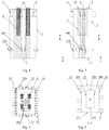
- Figs. 1-3 are schematic front, side and top cross-section views of a circulating fluidized bed boiler with a variable cross-section furnace according to an embodiment of the present invention, respectively;
- Figs. 4-5 are schematic cross-section views of a circulating fluidized bed boiler with a variable cross-section furnace according to the embodiment of the present invention at a lower level and an upper level, respectively.
- the water-cooled column 4 is formed by connecting membrane water-cooled walls 41, and comprises: a lower section A in a form of a single column at a lower portion of the furnace, an upper section in a form of double columns at middle and upper portions of the furnace.
- the upper section comprises a sub-column B and a sub-column C, and a transition section configured to connect the lower section A with the sub-sections B, C.
- the lower section A comprises: a water-cooled column front wall 401 and a water-cooled column rear wall 402 which are arranged opposite to each other and face towards the furnace front wall 21 and the furnace rear wall 22, respectively; and a water-cooled column left side wall 403 and a water-cooled column right side wall 404 which are arranged opposite to each other and face towards the furnace left side wall and the furnace right side wall, respectively.
- the sub-columns B and C of the upper section of the water-cooled column may be arranged side by side and have identical cross-section.
- the sub-column B comprises: a front wall 405 and a rear wall 406 which are arranged opposite to each other and in parallel with the furnace front wall 21, respectively; and a left side wall 407 and a right side wall 408 which are arranged opposite to each other and face towards the furnace left side wall 23 and the furnace right side wall 24, respectively.
- the sub-column C comprises: a front wall 409 and a rear wall 410 which are arranged opposite to each other and in parallel with the furnace rear wall 22, respectively; and a left side wall 411 and a right side wall 412 which are arranged opposite to each other and face towards the furnace left side wall 23 and the furnace right side wall 24, respectively.
- each of the sub-columns may have a cross-section shape chosen from a rectangle, a circle, a regular hexagon and a regular octagon.
- the water-cooled column 4 extends upward from the air distribution plate 1 to the ceiling 3 of the furnace.
- both the oppositely arranged side walls 403 and 404 of the lower section A at the lower portion of the water-cooled column 4 are inclined towards inner sides of the water-cooled column from a certain position above the air distribution plate 1 and below the secondary ports 400 inside the water-cooled column 4, so that the distance between the side walls 403 and 404 is reduced.
- both the side walls 403 and 404 turn to vertically extend upward to the ceiling 3.
- the oppositely arranged side walls 401 and 402 of the lower section A extend vertically to the ceiling 3 from bottom to top.
- an internal space of the water-cooled column is formed as a comb tooth-shaped space with two comb teeth, which are communicated with each other.
- Lower portions of the furnace front wall 21 and the furnace rear wall 22 are inclined outwardly from a certain level above the air distribution plate 1, and outer secondary air ports 220 are provided outside the outwardly inclined sections.
- Both the furnace left side wall 23 and the furnace right side wall 24 extend vertically from bottom to top, outer secondary air ports 220 are also provided outside lower portions of the side walls 23, 24.
- the furnace outlets 5 connected with the cyclone separator (not shown) are provided in upper portions of the furnace left side wall 23 and the furnace right side wall 24.
- platen heating surfaces 6 are provided at upper portions outside the left side wall 407 and the right side wall 408 of the sub-column B and outside the left side wall 411 and the right side wall 412 of the sub-column C.
- platen heating surfaces 6 may also be provided at upper portions outside the front wall 405 and the rear wall 406 of the sub-column B and outside the front wall 409 and the rear wall 410 of the sub-column C.
- the rear wall 406 of the sub-column B and the front wall 409 of the sub-column C extend vertically to the ceiling 3 from bottom to top.
- the front wall 405 of the sub-column B and the furnace front wall 21 are arranged in parallel with each other;
- the rear wall 406 of the sub-column B and the front wall 409 of the sub-column C are arranged in parallel with each other;
- the rear wall 410 of the sub-column C and the furnace rear wall 22 are arranged in parallel with each other;
- the left side wall 407 and the right side wall 408 of the sub-column B and the left side wall 411 and the right side wall 412 of the sub-column C are arranged in parallel with the furnace left side wall 23 and the furnace right side wall 24.
- Water-cooled wall tubes at left half of the rear wall 406 of the sub-column B are connected with water-cooled wall tubes at front portion of the left side wall 403 of the lower section A through connection tubes; water-cooled wall tubes at right half of the rear wall 406 of the sub-column B are connected with water-cooled wall tubes at front portion of the right side wall 404 of the lower section A through connection tubes.
- water-cooled wall tubes at left half of the front wall 409 of the sub-column C are connected with water-cooled wall tubes at rear portion of the left side wall 403 of the lower section A through connection tubes; water-cooled wall tubes at right half of the front wall 409 of the sub-column C are connected with water-cooled wall tubes at rear portion of the right side wall 404 of the lower section A through connection tubes.
- the lower section A at the lower portion of the furnace is transited to the upper section having double columns.
- Figs. 6-7 are schematic front and top cross-section views of a circulating fluidized bed boiler with a variable cross-section furnace according to another embodiment of the present invention, respectively. This embodiment is different from the previously described embodiment in a structure of the water-cooled column upper section, while the other structure is similar to the previously described embodiment.
- the front wall 401 and the rear wall 402 (referring to Fig. 4 ) of the lower section A, the front wall 405 and the rear wall 406 (referring to Fig. 5 ) of the sub-column B, the front wall 409 and the rear wall 410 (referring to Fig. 5 ) of the sub-column C extend vertically to the ceiling 3 from bottom to top.
- Lower portions of the furnace front wall 21 and the furnace rear wall 22 are inclined outwardly from a certain level above the air distribution plate 1, and outer secondary air ports 220 are provided on the inclined sections.
- the width between the left side wall 403 and the right side wall 404 (referring to Fig. 4 ) of the lower section A is identical to the width between the left side wall 407 and the right side wall 408 (referring to Fig. 5 ) of the sub-column B, and to the width between the left side wall 411 and the right side wall 412 (referring to Fig. 5 ) of the sub-column C.
- inner secondary air ports 400 are provided in inner sides of the left side wall 407 and the right side wall 408 of the sub-column B and in inner sides of the left side wall 411 and the right side wall 412 of the sub-column C at a certain level thereof.
- inner secondary air ports 400 may also be provided in the inner sides of the front wall 405 and the rear wall 406 of the sub-column B and in the inner sides of the front wall 409 and the rear wall 410 of the sub-column C.
- Lower portions of the furnace left side wall 23 and the furnace right side wall 24 are inclined outwardly from a certain level above the air distribution plate 1 to a predefined height, and then extend vertically to the ceiling 3 from bottom to top.
- Outer secondary air ports 220 are provided outside the inclined section of the lower portions of the furnace left side wall 23 and the furnace right side wall 24 at the same level as the inner secondary air ports 400 in the inner sides of the left and right side walls of the sub-columns B, C.
- Platen heating surfaces 6 are provided on outer sides of upper portions of the left side wall 407 and the right side wall 408 of the sub-column B and upper portions of the left side wall 411 and the right side wall 412 of the sub-column C.
- platen heating surfaces 6 may also be provided on inner sides of the furnace left side wall 23 and the furnace right side wall 24 between two adjacent furnace outlets 5, and provided on outer sides of upper portions of the front wall 405 and the rear wall 406 of the sub-column B and upper portions of the front wall 409 and the rear wall 410 of the sub-column C, according to requirements for heat absorption of the furnace.
- Figs. 8-10 are schematic front, side and top cross-section views of a circulating fluidized bed boiler with a variable cross-section furnace according to further another embodiment of the present invention, respectively;
- Fig. 11 is a schematic cross-section view of a circulating fluidized bed boiler with a variable cross-section furnace according to the embodiment of the present invention at an upper level. This embodiment is different from the embodiment shown in Figs. 1-3 in a structure of the upper section, while the other structure is similar to the first embodiment.
- the present invention provides another comb tooth type water-cooled column, wherein the lower section at a lower portion of the furnace is formed as a single column, which is connected to an upper section having three parallel columns at middle and upper portions of the furnace through a transition section.
- a comb tooth-shaped space with three comb teeth is formed inside the water-cooled column.
- Both the left and right side walls 403 and 404 (see Fig.4 ) of the lower section A are inclined towards inner sides of the water-cooled column from a certain level, and then extend vertically upward to the ceiling 3 from bottom to top after the inclined sections reach to a certain level.
- Inner secondary air ports 400 are provided in an inner side of each side of the inclined transition section of the water-cooled wall.
- the front wall 401 and the rear wall 402 (referring to Fig. 4 ) of the lower section A extend vertically upward to the ceiling 3 from bottom to top so as to form a front wall of a sub-column D and a rear wall of a sub-column F at an upper section of the water-cooled column at a certain level, respectively.
- Outer secondary air ports 220 are also provided outside the lower portions of the furnace front wall 21, the furnace rear wall 22, the left side wall 23 and the right side wall 24, at levels corresponding to the levels of the inner secondary air ports 400.
- the water-cooled wall tubes at the middle of the left and right side walls 403, 404 of the lower section A are inclined towards inner sides of the water-cooled column at a certain level above the air distribution plate 1 and extend to a predefined height, and then extend to form left and right side walls of the sub-columns D, E, F of the upper section, respectively.
- the cross-sections of the sub-columns D, E, F are in a rectangle shape, and have identical cross-section area.
- Inner secondary air ports 400 are provided on inner sides of lower portions of four membrane water-cooled walls of the sub-columns D, E, F, respectively.
- Outer secondary air ports 220 are provided outside respective furnace side walls at the same level as the inner secondary air ports 400.
- Platen heating surfaces 6 are provided on upper portions of outer sides of the left and right side walls of the sub-columns D, E, F of the upper section, and platen heating surfaces 6 may also be provided on upper portions of outer sides of the front wall of the sub-column D and the rear wall of the sub-column F.
- platen heating surfaces 6 may also be provided on upper portions of outer sides of the rear wall of the sub-column D, the front and rear walls of the sub-column E, and the front wall of the sub-column F.
- the present invention provides a water-cooled column used in a circulating fluidized bed boiler furnace, wherein the water-cooled column is formed by connecting membrane water-cooled walls, and the water-cooled column comprises: a lower section A configured to be a single column and provided with inner secondary air ports 400 on a side wall thereof; an upper section comprising a plurality of sub-columns B, C; D, E, F; and a transition section, through which the membrane water-cooled walls at the lower section A extend to the upper section, wherein the upper section is connected to the lower section by means of the transition section to form a flow passage for working medium of the water-cooled column, which run from the air distribution plate to the ceiling.
- Each of the sub-columns is formed by connecting extension portions extending upward from respective membrane water-cooled walls in the membrane water-cooled walls, which are connected to form the lower section, and the plurality of sub-columns are separated from each other.
- the upper section comprises two sub-columns B, C.
- the upper section comprises three sub-columns D, E, F arranged in a line and equidistantly spaced apart from each other.
- the upper section comprises four sub-columns, among which a cross-shaped gap is defined.
- a cross-shaped gap is defined.
- each of the sub-columns has an identical cross-section with any other sub-columns. Further, each of the sub-columns has an identical cross-section area with any other sub-columns.
- each of the sub-columns has a cross-section shape chosen from a rectangle, a circle, a regular hexagon and a regular octagon.
- additional inner secondary air ports 400 are provided on opposite side walls of at least a pair of adjacent sub-columns.
- the present invention also relates to a circulating fluidized bed boiler furnace, comprising furnace side walls, a ceiling 3, an air distribution plate 1 and a water-cooled column 4 provided between the air distribution plate 1 and the ceiling 3, wherein a furnace combustion space is enclosed by the water-cooled column side walls, the furnace side walls, the air distribution plate and the ceiling, inner secondary air ports 400 for injecting secondary air into the furnace combustion space are provided at a lower portion of the water-cooled column side walls, and outer secondary air ports 220 for injecting secondary air into the furnace combustion space are provided at a lower portion of the furnace side walls.
- an extended heating surface 6 is arranged outside at least one of the sub-columns.
- the present invention also relates to a circulating fluidized bed boiler, comprising the above described circulating fluidized bed boiler furnace.
- the water-cooled column is divided into a single column lower section and a multi-column upper section, and a transition section is provided between the upper section and the lower section.
- the upper section is connected with the lower section through the transition section, so that comb tooth-shaped communicated spaces are formed in the water-cooled column.
- the membrane-type wall tubes of the lower section extend upward to form the membrane-type wall tubes of the upper section, so that a flow passage for working medium in the water-cooled column is formed from the air distribution plate to the ceiling.
- a combustion space at the lower portion of the furnace where the lower section is located has an annular cross-section
- the air distribution plate also has an annular cross-section
- a combustion space at the middle and upper portion of the furnace where the upper section is located has a shape similar to the Chinese character " ", " " or the like.
Landscapes
- Engineering & Computer Science (AREA)
- Chemical & Material Sciences (AREA)
- Combustion & Propulsion (AREA)
- Mechanical Engineering (AREA)
- General Engineering & Computer Science (AREA)
- Physics & Mathematics (AREA)
- Thermal Sciences (AREA)
- Fluidized-Bed Combustion And Resonant Combustion (AREA)
Claims (11)
- Wassergekühlte Säule (4) für eine zirkulierende Wirbelschichtfeuerung, wobei die wassergekühlte Säule (4) durch verbindende wassergekühlte Membranwände (41) gebildet ist, und
dadurch gekennzeichnet, dass die wassergekühlte Säule (4) aufweist:einen unteren Abschnitt (A), der als einzelne Säule ausgebildet und an einer Seitenwand mit inneren Sekundärluftöffnungen (400) versehen ist;einen oberen Abschnitt, der eine Vielzahl von Teilsäulen (B-F) aufweist; undeinen Übergangsabschnitt, durch den die wassergekühlten Membranwände (41) aus dem unteren Abschnitt (A) in den oberen Bereich Abschnitt verlaufen,wobei jede der Teilsäulen (B-F) durch verbindende Verlängerungsteilen gebildet ist, die von entsprechenden wassergekühlten Membranwänden (41) in den wassergekühlten Membranwänden, die zur Bildung des unteren Abschnitts (A) verbunden sind, nach oben verlaufen, und wobei die Vielzahl von Teilsäulen (B-F) voneinander getrennt sind. - Wassergekühlte Säule (4) nach Anspruch 1, wobei der obere Abschnitt zwei Teilsäulen (B, C) aufweist.
- Wassergekühlte Säule (4) nach Anspruch 1, dadurch gekennzeichnet, dass der obere Abschnitt drei in einer Linie angeordnete und äquidistant voneinander beabstandete Teilsäulen (D, E, F) aufweist.
- Wassergekühlte Säule (4) nach Anspruch 1, dadurch gekennzeichnet, dass der obere Abschnitt vier Teilsäulen aufweist, zwischen denen ein kreuzförmiger Spalt ausgebildet ist.
- Wassergekühlte Säule (4) nach einem der Ansprüche 1 bis 4, wobei jede der Teilsäulen einen identischen Querschnitt wie alle anderen Teilsäulen aufweist.
- Wassergekühlte Säule (4) nach Anspruch 5, wobei jede der Teilsäulen eine identische Querschnittsfläche wie alle anderen Teilsäulen aufweist.
- Wassergekühlte Säule (4) nach einem der Ansprüche 1 bis 4, wobei jede der Teilsäulen eine Querschnittsform hat, die aus einem Rechteck, einem Kreis, einem regelmäßigen Sechseck und einem regelmäßigen Achteck ausgewählt ist.
- Wassergekühlte Säule (4) nach einem der Ansprüche 1 bis 4, wobei zusätzliche innere Sekundärluftöffnungen (400) an gegenüberliegenden Seitenwänden von mindestens einem Paar benachbarter Teilsäulen vorgesehen sind.
- Zirkulierende Wirbelschichtfeuerung, die Ofenseitenwände (21-24), eine Decke (3), eine Luftverteilungsplatte (1) und eine wassergekühlten Säule (4) aufweist, die zwischen der Luftverteilungsplatte (1) und der Decke (3) vorgesehen ist, wobei die wassergekühlte Säule (4) durch verbindende Seitenwände gebildet ist, die durch wassergekühlte Membranwände (41) gebildet sind, ein Ofenverbrennungsraum durch die wassergekühlten Säulenseitenwände, die Ofenseitenwände (21-24), die Luftverteilungsplatte (1) und die Decke (3) eingeschlossen ist, wobei innere Sekundärluftöffnungen (400) zum Einblasen von Sekundärluft in den Ofenverbrennungsraum an einem unteren Abschnitt der wassergekühlten Säulenseitenwände vorgesehen sind, und äußere Sekundärluftöffnungen (220) zum Einblasen von Sekundärluft in den Ofenverbrennungsraum an einem unteren Abschnitt der Ofenseitenwände (21-24) vorgesehen sind,
wobei die wassergekühlte Säule (4) die wassergekühlte Säule nach einem der Ansprüche 1-8 ist. - Zirkulierende Wirbelschichtfeuerung nach Anspruch 9, wobei außerhalb mindestens einer der Teilsäulen eine erweiterte Heizfläche angeordnet ist.
- Zirkulierender Wirbelschichtkessel, aufweisend die zirkulierende Wirbelschichtfeuerung nach Anspruch 9 oder 10.
Priority Applications (1)
| Application Number | Priority Date | Filing Date | Title |
|---|---|---|---|
| PL14871950T PL3086037T3 (pl) | 2013-12-20 | 2014-10-13 | Kolumna chłodzona wodą i palenisko mające taką kolumnę |
Applications Claiming Priority (2)
| Application Number | Priority Date | Filing Date | Title |
|---|---|---|---|
| CN201310712004.8A CN104728856B (zh) | 2013-12-20 | 2013-12-20 | 梳齿型水冷柱及具有该水冷柱的炉膛 |
| PCT/CN2014/088490 WO2015090104A1 (zh) | 2013-12-20 | 2014-10-13 | 梳齿型水冷柱及具有该水冷柱的炉膛 |
Publications (3)
| Publication Number | Publication Date |
|---|---|
| EP3086037A1 EP3086037A1 (de) | 2016-10-26 |
| EP3086037A4 EP3086037A4 (de) | 2017-08-09 |
| EP3086037B1 true EP3086037B1 (de) | 2021-12-01 |
Family
ID=53402076
Family Applications (1)
| Application Number | Title | Priority Date | Filing Date |
|---|---|---|---|
| EP14871950.3A Active EP3086037B1 (de) | 2013-12-20 | 2014-10-13 | Wassergekühlte säule und herd damit |
Country Status (6)
| Country | Link |
|---|---|
| US (1) | US10495298B2 (de) |
| EP (1) | EP3086037B1 (de) |
| KR (1) | KR102091502B1 (de) |
| CN (1) | CN104728856B (de) |
| PL (1) | PL3086037T3 (de) |
| WO (1) | WO2015090104A1 (de) |
Families Citing this family (2)
| Publication number | Priority date | Publication date | Assignee | Title |
|---|---|---|---|---|
| CN110056868A (zh) * | 2019-04-24 | 2019-07-26 | 哈尔滨理工大学 | 一种中间进气自动冷却流化床 |
| CN112443833B (zh) * | 2019-09-05 | 2023-01-06 | 中国科学院工程热物理研究所 | 燃烧器底置煤粉锅炉及其控制方法 |
Family Cites Families (19)
| Publication number | Priority date | Publication date | Assignee | Title |
|---|---|---|---|---|
| AT339344B (de) * | 1972-11-16 | 1977-10-10 | Waagner Biro Ag | Rohrbundeldampferzeuger, insbesondere fur kernkraftwerke |
| US4253425A (en) * | 1979-01-31 | 1981-03-03 | Foster Wheeler Energy Corporation | Internal dust recirculation system for a fluidized bed heat exchanger |
| CA2032711C (en) | 1990-12-19 | 1994-02-01 | George Cooke | Boiler |
| US5140950A (en) * | 1991-05-15 | 1992-08-25 | Foster Wheeler Energy Corporation | Fluidized bed combustion system and method having an integral recycle heat exchanger with recycle rate control and backflow sealing |
| AT401287B (de) | 1994-10-17 | 1996-07-25 | Austrian Energy & Environment | Kühlflächenauskleidung |
| US5678497A (en) * | 1996-04-30 | 1997-10-21 | Foster Wheeler Energy International, Inc. | Apparatus for distributing secondary air into a large scale circulating fluidized bed |
| US5836257A (en) * | 1996-12-03 | 1998-11-17 | Mcdermott Technology, Inc. | Circulating fluidized bed furnace/reactor with an integral secondary air plenum |
| FI105499B (fi) * | 1998-11-20 | 2000-08-31 | Foster Wheeler Energia Oy | Menetelmä ja laite leijupetireaktorissa |
| US6532905B2 (en) * | 2001-07-17 | 2003-03-18 | The Babcock & Wilcox Company | CFB with controllable in-bed heat exchanger |
| US7244400B2 (en) * | 2003-11-25 | 2007-07-17 | Foster Wheeler Energy Corporation | Fluidized bed reactor system having an exhaust gas plenum |
| CN100523606C (zh) | 2006-12-07 | 2009-08-05 | 中国科学院工程热物理研究所 | 带水冷柱的循环流化床锅炉炉膛 |
| CN101614390A (zh) * | 2006-12-07 | 2009-12-30 | 中国科学院工程热物理研究所 | 带水冷柱的循环流化床锅炉炉膛 |
| CN100575782C (zh) * | 2007-02-07 | 2009-12-30 | 中国科学院工程热物理研究所 | 带受热屏的循环流化床锅炉炉膛 |
| CN101457304B (zh) | 2008-12-31 | 2011-04-27 | 邓小宝 | 中心回燃内热蓄热式节能高效炉罐一体化还原炉系统 |
| US8622029B2 (en) * | 2009-09-30 | 2014-01-07 | Babcock & Wilcox Power Generation Group, Inc. | Circulating fluidized bed (CFB) with in-furnace secondary air nozzles |
| CN101718430B (zh) * | 2009-12-22 | 2011-05-04 | 浙江大学 | 循环流化床锅炉带二次风喷射的十字受热屏 |
| CN102226518B (zh) * | 2011-02-01 | 2013-03-06 | 中国科学院工程热物理研究所 | 大型循环流化床锅炉 |
| ES2637364T3 (es) * | 2012-03-20 | 2017-10-13 | General Electric Technology Gmbh | Caldera de lecho fluidizado circulante |
| CN102997231B (zh) * | 2012-12-31 | 2015-06-24 | 中国科学院工程热物理研究所 | 大型循环流化床锅炉、布风装置和布风装置组件 |
-
2013
- 2013-12-20 CN CN201310712004.8A patent/CN104728856B/zh active Active
-
2014
- 2014-10-13 WO PCT/CN2014/088490 patent/WO2015090104A1/zh not_active Ceased
- 2014-10-13 KR KR1020167019115A patent/KR102091502B1/ko active Active
- 2014-10-13 EP EP14871950.3A patent/EP3086037B1/de active Active
- 2014-10-13 US US15/104,959 patent/US10495298B2/en active Active
- 2014-10-13 PL PL14871950T patent/PL3086037T3/pl unknown
Non-Patent Citations (1)
| Title |
|---|
| None * |
Also Published As
| Publication number | Publication date |
|---|---|
| PL3086037T3 (pl) | 2022-04-04 |
| KR102091502B1 (ko) | 2020-03-23 |
| WO2015090104A1 (zh) | 2015-06-25 |
| US20160320051A1 (en) | 2016-11-03 |
| EP3086037A4 (de) | 2017-08-09 |
| US10495298B2 (en) | 2019-12-03 |
| CN104728856A (zh) | 2015-06-24 |
| KR20160120718A (ko) | 2016-10-18 |
| CN104728856B (zh) | 2017-03-01 |
| EP3086037A1 (de) | 2016-10-26 |
Similar Documents
| Publication | Publication Date | Title |
|---|---|---|
| EP2672179B1 (de) | Grossflächiger zirkulations-wirbelbettkessel | |
| WO2017088742A1 (zh) | 一种低负荷下高流动稳定性的超临界循环流化床锅炉水冷壁及实现低质量流速的方法 | |
| KR101667503B1 (ko) | 대형 순환 유동층 보일러, 공기 분배 장치 및 공기 분배 장치 어셈블리 | |
| EP2634484A1 (de) | Kessel mit zirkulierendem wirbelbett | |
| BR112015031697B1 (pt) | Coletor de mistura de líquido, uso e método e coluna de troca de calor ou transferência de massa | |
| US10495298B2 (en) | Comb tooth type water-cooled column and furnace having the same | |
| KR101940356B1 (ko) | 막힘 방지형 증기 발생기 튜브 번들 | |
| US11603989B2 (en) | Circulating fluidized bed boiler with a loopseal heat exchanger | |
| JP3990202B2 (ja) | 内部熱交換型蒸留塔 | |
| TW201723304A (zh) | 在一次通過的水平蒸發器中之管排列 | |
| CN215136897U (zh) | 一种用于co2解吸的降膜再沸器 | |
| EP3045809B1 (de) | Zirkulierender wirbelbett-kesselofen mit einem wassergekühlten zylinder mit variablem querschnitt | |
| KR101378347B1 (ko) | 증기 발생 보일러 | |
| CN105698165B (zh) | 一种循环流化床锅炉的炉膛结构 | |
| CN205897096U (zh) | 循环流化床锅炉炉膛屏式受热面布置结构 | |
| CN103216809B (zh) | 至少一根集中下降管设置在炉膛中的循环流化床锅炉 | |
| CN206891195U (zh) | 热解炉 | |
| JP6173797B2 (ja) | 熱交換器、及び給湯器 | |
| JP2013066841A (ja) | 多重効用造水装置における分割バンドルによる蒸気流制御システム | |
| JP2009041907A (ja) | 吸収冷温水機用再生器 | |
| CN102226646B (zh) | 提高工业炉窑无焰加热段换热效率的炉膛结构 | |
| JP4925853B2 (ja) | 反応炉 | |
| JPH02229886A (ja) | 炭化水素の熱分解炉 | |
| CN108827042A (zh) | 一种翅片管流化床取热器 | |
| JP2011226678A (ja) | 流体加熱装置 |
Legal Events
| Date | Code | Title | Description |
|---|---|---|---|
| PUAI | Public reference made under article 153(3) epc to a published international application that has entered the european phase |
Free format text: ORIGINAL CODE: 0009012 |
|
| 17P | Request for examination filed |
Effective date: 20160615 |
|
| AK | Designated contracting states |
Kind code of ref document: A1 Designated state(s): AL AT BE BG CH CY CZ DE DK EE ES FI FR GB GR HR HU IE IS IT LI LT LU LV MC MK MT NL NO PL PT RO RS SE SI SK SM TR |
|
| AX | Request for extension of the european patent |
Extension state: BA ME |
|
| DAX | Request for extension of the european patent (deleted) | ||
| A4 | Supplementary search report drawn up and despatched |
Effective date: 20170712 |
|
| RIC1 | Information provided on ipc code assigned before grant |
Ipc: F22B 31/00 20060101ALI20170706BHEP Ipc: F23C 10/10 20060101AFI20170706BHEP |
|
| STAA | Information on the status of an ep patent application or granted ep patent |
Free format text: STATUS: EXAMINATION IS IN PROGRESS |
|
| 17Q | First examination report despatched |
Effective date: 20200710 |
|
| GRAP | Despatch of communication of intention to grant a patent |
Free format text: ORIGINAL CODE: EPIDOSNIGR1 |
|
| STAA | Information on the status of an ep patent application or granted ep patent |
Free format text: STATUS: GRANT OF PATENT IS INTENDED |
|
| INTG | Intention to grant announced |
Effective date: 20210714 |
|
| GRAS | Grant fee paid |
Free format text: ORIGINAL CODE: EPIDOSNIGR3 |
|
| GRAA | (expected) grant |
Free format text: ORIGINAL CODE: 0009210 |
|
| STAA | Information on the status of an ep patent application or granted ep patent |
Free format text: STATUS: THE PATENT HAS BEEN GRANTED |
|
| AK | Designated contracting states |
Kind code of ref document: B1 Designated state(s): AL AT BE BG CH CY CZ DE DK EE ES FI FR GB GR HR HU IE IS IT LI LT LU LV MC MK MT NL NO PL PT RO RS SE SI SK SM TR |
|
| REG | Reference to a national code |
Ref country code: GB Ref legal event code: FG4D |
|
| REG | Reference to a national code |
Ref country code: AT Ref legal event code: REF Ref document number: 1452104 Country of ref document: AT Kind code of ref document: T Effective date: 20211215 Ref country code: CH Ref legal event code: EP |
|
| REG | Reference to a national code |
Ref country code: IE Ref legal event code: FG4D |
|
| REG | Reference to a national code |
Ref country code: DE Ref legal event code: R096 Ref document number: 602014081578 Country of ref document: DE |
|
| REG | Reference to a national code |
Ref country code: LT Ref legal event code: MG9D |
|
| REG | Reference to a national code |
Ref country code: NL Ref legal event code: MP Effective date: 20211201 |
|
| REG | Reference to a national code |
Ref country code: AT Ref legal event code: MK05 Ref document number: 1452104 Country of ref document: AT Kind code of ref document: T Effective date: 20211201 |
|
| PG25 | Lapsed in a contracting state [announced via postgrant information from national office to epo] |
Ref country code: RS Free format text: LAPSE BECAUSE OF FAILURE TO SUBMIT A TRANSLATION OF THE DESCRIPTION OR TO PAY THE FEE WITHIN THE PRESCRIBED TIME-LIMIT Effective date: 20211201 Ref country code: LT Free format text: LAPSE BECAUSE OF FAILURE TO SUBMIT A TRANSLATION OF THE DESCRIPTION OR TO PAY THE FEE WITHIN THE PRESCRIBED TIME-LIMIT Effective date: 20211201 Ref country code: FI Free format text: LAPSE BECAUSE OF FAILURE TO SUBMIT A TRANSLATION OF THE DESCRIPTION OR TO PAY THE FEE WITHIN THE PRESCRIBED TIME-LIMIT Effective date: 20211201 Ref country code: BG Free format text: LAPSE BECAUSE OF FAILURE TO SUBMIT A TRANSLATION OF THE DESCRIPTION OR TO PAY THE FEE WITHIN THE PRESCRIBED TIME-LIMIT Effective date: 20220301 Ref country code: AT Free format text: LAPSE BECAUSE OF FAILURE TO SUBMIT A TRANSLATION OF THE DESCRIPTION OR TO PAY THE FEE WITHIN THE PRESCRIBED TIME-LIMIT Effective date: 20211201 |
|
| PG25 | Lapsed in a contracting state [announced via postgrant information from national office to epo] |
Ref country code: SE Free format text: LAPSE BECAUSE OF FAILURE TO SUBMIT A TRANSLATION OF THE DESCRIPTION OR TO PAY THE FEE WITHIN THE PRESCRIBED TIME-LIMIT Effective date: 20211201 Ref country code: NO Free format text: LAPSE BECAUSE OF FAILURE TO SUBMIT A TRANSLATION OF THE DESCRIPTION OR TO PAY THE FEE WITHIN THE PRESCRIBED TIME-LIMIT Effective date: 20220301 Ref country code: LV Free format text: LAPSE BECAUSE OF FAILURE TO SUBMIT A TRANSLATION OF THE DESCRIPTION OR TO PAY THE FEE WITHIN THE PRESCRIBED TIME-LIMIT Effective date: 20211201 Ref country code: HR Free format text: LAPSE BECAUSE OF FAILURE TO SUBMIT A TRANSLATION OF THE DESCRIPTION OR TO PAY THE FEE WITHIN THE PRESCRIBED TIME-LIMIT Effective date: 20211201 Ref country code: GR Free format text: LAPSE BECAUSE OF FAILURE TO SUBMIT A TRANSLATION OF THE DESCRIPTION OR TO PAY THE FEE WITHIN THE PRESCRIBED TIME-LIMIT Effective date: 20220302 Ref country code: ES Free format text: LAPSE BECAUSE OF FAILURE TO SUBMIT A TRANSLATION OF THE DESCRIPTION OR TO PAY THE FEE WITHIN THE PRESCRIBED TIME-LIMIT Effective date: 20211201 |
|
| PG25 | Lapsed in a contracting state [announced via postgrant information from national office to epo] |
Ref country code: NL Free format text: LAPSE BECAUSE OF FAILURE TO SUBMIT A TRANSLATION OF THE DESCRIPTION OR TO PAY THE FEE WITHIN THE PRESCRIBED TIME-LIMIT Effective date: 20211201 |
|
| PG25 | Lapsed in a contracting state [announced via postgrant information from national office to epo] |
Ref country code: SM Free format text: LAPSE BECAUSE OF FAILURE TO SUBMIT A TRANSLATION OF THE DESCRIPTION OR TO PAY THE FEE WITHIN THE PRESCRIBED TIME-LIMIT Effective date: 20211201 Ref country code: SK Free format text: LAPSE BECAUSE OF FAILURE TO SUBMIT A TRANSLATION OF THE DESCRIPTION OR TO PAY THE FEE WITHIN THE PRESCRIBED TIME-LIMIT Effective date: 20211201 Ref country code: RO Free format text: LAPSE BECAUSE OF FAILURE TO SUBMIT A TRANSLATION OF THE DESCRIPTION OR TO PAY THE FEE WITHIN THE PRESCRIBED TIME-LIMIT Effective date: 20211201 Ref country code: PT Free format text: LAPSE BECAUSE OF FAILURE TO SUBMIT A TRANSLATION OF THE DESCRIPTION OR TO PAY THE FEE WITHIN THE PRESCRIBED TIME-LIMIT Effective date: 20220401 Ref country code: EE Free format text: LAPSE BECAUSE OF FAILURE TO SUBMIT A TRANSLATION OF THE DESCRIPTION OR TO PAY THE FEE WITHIN THE PRESCRIBED TIME-LIMIT Effective date: 20211201 Ref country code: CZ Free format text: LAPSE BECAUSE OF FAILURE TO SUBMIT A TRANSLATION OF THE DESCRIPTION OR TO PAY THE FEE WITHIN THE PRESCRIBED TIME-LIMIT Effective date: 20211201 |
|
| REG | Reference to a national code |
Ref country code: DE Ref legal event code: R097 Ref document number: 602014081578 Country of ref document: DE |
|
| PG25 | Lapsed in a contracting state [announced via postgrant information from national office to epo] |
Ref country code: IS Free format text: LAPSE BECAUSE OF FAILURE TO SUBMIT A TRANSLATION OF THE DESCRIPTION OR TO PAY THE FEE WITHIN THE PRESCRIBED TIME-LIMIT Effective date: 20220401 |
|
| PLBE | No opposition filed within time limit |
Free format text: ORIGINAL CODE: 0009261 |
|
| STAA | Information on the status of an ep patent application or granted ep patent |
Free format text: STATUS: NO OPPOSITION FILED WITHIN TIME LIMIT |
|
| PG25 | Lapsed in a contracting state [announced via postgrant information from national office to epo] |
Ref country code: DK Free format text: LAPSE BECAUSE OF FAILURE TO SUBMIT A TRANSLATION OF THE DESCRIPTION OR TO PAY THE FEE WITHIN THE PRESCRIBED TIME-LIMIT Effective date: 20211201 Ref country code: AL Free format text: LAPSE BECAUSE OF FAILURE TO SUBMIT A TRANSLATION OF THE DESCRIPTION OR TO PAY THE FEE WITHIN THE PRESCRIBED TIME-LIMIT Effective date: 20211201 |
|
| 26N | No opposition filed |
Effective date: 20220902 |
|
| PG25 | Lapsed in a contracting state [announced via postgrant information from national office to epo] |
Ref country code: SI Free format text: LAPSE BECAUSE OF FAILURE TO SUBMIT A TRANSLATION OF THE DESCRIPTION OR TO PAY THE FEE WITHIN THE PRESCRIBED TIME-LIMIT Effective date: 20211201 |
|
| PG25 | Lapsed in a contracting state [announced via postgrant information from national office to epo] |
Ref country code: MC Free format text: LAPSE BECAUSE OF FAILURE TO SUBMIT A TRANSLATION OF THE DESCRIPTION OR TO PAY THE FEE WITHIN THE PRESCRIBED TIME-LIMIT Effective date: 20211201 Ref country code: IT Free format text: LAPSE BECAUSE OF FAILURE TO SUBMIT A TRANSLATION OF THE DESCRIPTION OR TO PAY THE FEE WITHIN THE PRESCRIBED TIME-LIMIT Effective date: 20211201 |
|
| REG | Reference to a national code |
Ref country code: CH Ref legal event code: PL |
|
| REG | Reference to a national code |
Ref country code: BE Ref legal event code: MM Effective date: 20221031 |
|
| GBPC | Gb: european patent ceased through non-payment of renewal fee |
Effective date: 20221013 |
|
| PG25 | Lapsed in a contracting state [announced via postgrant information from national office to epo] |
Ref country code: LU Free format text: LAPSE BECAUSE OF NON-PAYMENT OF DUE FEES Effective date: 20221013 |
|
| PG25 | Lapsed in a contracting state [announced via postgrant information from national office to epo] |
Ref country code: LI Free format text: LAPSE BECAUSE OF NON-PAYMENT OF DUE FEES Effective date: 20221031 Ref country code: CH Free format text: LAPSE BECAUSE OF NON-PAYMENT OF DUE FEES Effective date: 20221031 |
|
| PG25 | Lapsed in a contracting state [announced via postgrant information from national office to epo] |
Ref country code: BE Free format text: LAPSE BECAUSE OF NON-PAYMENT OF DUE FEES Effective date: 20221031 |
|
| PG25 | Lapsed in a contracting state [announced via postgrant information from national office to epo] |
Ref country code: IE Free format text: LAPSE BECAUSE OF NON-PAYMENT OF DUE FEES Effective date: 20221013 Ref country code: GB Free format text: LAPSE BECAUSE OF NON-PAYMENT OF DUE FEES Effective date: 20221013 |
|
| PG25 | Lapsed in a contracting state [announced via postgrant information from national office to epo] |
Ref country code: HU Free format text: LAPSE BECAUSE OF FAILURE TO SUBMIT A TRANSLATION OF THE DESCRIPTION OR TO PAY THE FEE WITHIN THE PRESCRIBED TIME-LIMIT; INVALID AB INITIO Effective date: 20141013 |
|
| PG25 | Lapsed in a contracting state [announced via postgrant information from national office to epo] |
Ref country code: CY Free format text: LAPSE BECAUSE OF FAILURE TO SUBMIT A TRANSLATION OF THE DESCRIPTION OR TO PAY THE FEE WITHIN THE PRESCRIBED TIME-LIMIT Effective date: 20211201 |
|
| PG25 | Lapsed in a contracting state [announced via postgrant information from national office to epo] |
Ref country code: MK Free format text: LAPSE BECAUSE OF FAILURE TO SUBMIT A TRANSLATION OF THE DESCRIPTION OR TO PAY THE FEE WITHIN THE PRESCRIBED TIME-LIMIT Effective date: 20211201 |
|
| PG25 | Lapsed in a contracting state [announced via postgrant information from national office to epo] |
Ref country code: MT Free format text: LAPSE BECAUSE OF FAILURE TO SUBMIT A TRANSLATION OF THE DESCRIPTION OR TO PAY THE FEE WITHIN THE PRESCRIBED TIME-LIMIT Effective date: 20211201 |
|
| PGFP | Annual fee paid to national office [announced via postgrant information from national office to epo] |
Ref country code: TR Payment date: 20250929 Year of fee payment: 12 |
|
| PGFP | Annual fee paid to national office [announced via postgrant information from national office to epo] |
Ref country code: DE Payment date: 20251014 Year of fee payment: 12 |
|
| PGFP | Annual fee paid to national office [announced via postgrant information from national office to epo] |
Ref country code: FR Payment date: 20251013 Year of fee payment: 12 |
|
| PGFP | Annual fee paid to national office [announced via postgrant information from national office to epo] |
Ref country code: PL Payment date: 20251001 Year of fee payment: 12 |