EP3086046A1 - Dispositif de climatisation et procédé d'alimentation de commandes à distance - Google Patents
Dispositif de climatisation et procédé d'alimentation de commandes à distance Download PDFInfo
- Publication number
- EP3086046A1 EP3086046A1 EP13899476.9A EP13899476A EP3086046A1 EP 3086046 A1 EP3086046 A1 EP 3086046A1 EP 13899476 A EP13899476 A EP 13899476A EP 3086046 A1 EP3086046 A1 EP 3086046A1
- Authority
- EP
- European Patent Office
- Prior art keywords
- remote controller
- unit
- indoor
- address
- indoor units
- Prior art date
- Legal status (The legal status is an assumption and is not a legal conclusion. Google has not performed a legal analysis and makes no representation as to the accuracy of the status listed.)
- Granted
Links
Images


Classifications
-
- F—MECHANICAL ENGINEERING; LIGHTING; HEATING; WEAPONS; BLASTING
- F24—HEATING; RANGES; VENTILATING
- F24F—AIR-CONDITIONING; AIR-HUMIDIFICATION; VENTILATION; USE OF AIR CURRENTS FOR SCREENING
- F24F11/00—Control or safety arrangements
- F24F11/30—Control or safety arrangements for purposes related to the operation of the system, e.g. for safety or monitoring
-
- F—MECHANICAL ENGINEERING; LIGHTING; HEATING; WEAPONS; BLASTING
- F24—HEATING; RANGES; VENTILATING
- F24F—AIR-CONDITIONING; AIR-HUMIDIFICATION; VENTILATION; USE OF AIR CURRENTS FOR SCREENING
- F24F11/00—Control or safety arrangements
- F24F11/30—Control or safety arrangements for purposes related to the operation of the system, e.g. for safety or monitoring
- F24F11/32—Responding to malfunctions or emergencies
- F24F11/38—Failure diagnosis
-
- F—MECHANICAL ENGINEERING; LIGHTING; HEATING; WEAPONS; BLASTING
- F24—HEATING; RANGES; VENTILATING
- F24F—AIR-CONDITIONING; AIR-HUMIDIFICATION; VENTILATION; USE OF AIR CURRENTS FOR SCREENING
- F24F11/00—Control or safety arrangements
- F24F11/50—Control or safety arrangements characterised by user interfaces or communication
- F24F11/52—Indication arrangements, e.g. displays
-
- F—MECHANICAL ENGINEERING; LIGHTING; HEATING; WEAPONS; BLASTING
- F24—HEATING; RANGES; VENTILATING
- F24F—AIR-CONDITIONING; AIR-HUMIDIFICATION; VENTILATION; USE OF AIR CURRENTS FOR SCREENING
- F24F11/00—Control or safety arrangements
- F24F11/50—Control or safety arrangements characterised by user interfaces or communication
- F24F11/56—Remote control
-
- F—MECHANICAL ENGINEERING; LIGHTING; HEATING; WEAPONS; BLASTING
- F24—HEATING; RANGES; VENTILATING
- F24F—AIR-CONDITIONING; AIR-HUMIDIFICATION; VENTILATION; USE OF AIR CURRENTS FOR SCREENING
- F24F11/00—Control or safety arrangements
- F24F11/62—Control or safety arrangements characterised by the type of control or by internal processing, e.g. using fuzzy logic, adaptive control or estimation of values
-
- F—MECHANICAL ENGINEERING; LIGHTING; HEATING; WEAPONS; BLASTING
- F24—HEATING; RANGES; VENTILATING
- F24F—AIR-CONDITIONING; AIR-HUMIDIFICATION; VENTILATION; USE OF AIR CURRENTS FOR SCREENING
- F24F11/00—Control or safety arrangements
- F24F11/62—Control or safety arrangements characterised by the type of control or by internal processing, e.g. using fuzzy logic, adaptive control or estimation of values
- F24F11/63—Electronic processing
-
- G—PHYSICS
- G05—CONTROLLING; REGULATING
- G05B—CONTROL OR REGULATING SYSTEMS IN GENERAL; FUNCTIONAL ELEMENTS OF SUCH SYSTEMS; MONITORING OR TESTING ARRANGEMENTS FOR SUCH SYSTEMS OR ELEMENTS
- G05B15/00—Systems controlled by a computer
- G05B15/02—Systems controlled by a computer electric
-
- G—PHYSICS
- G05—CONTROLLING; REGULATING
- G05F—SYSTEMS FOR REGULATING ELECTRIC OR MAGNETIC VARIABLES
- G05F1/00—Automatic systems in which deviations of an electric quantity from one or more predetermined values are detected at the output of the system and fed back to a device within the system to restore the detected quantity to its predetermined value or values, i.e. retroactive systems
- G05F1/66—Regulating electric power
-
- F—MECHANICAL ENGINEERING; LIGHTING; HEATING; WEAPONS; BLASTING
- F24—HEATING; RANGES; VENTILATING
- F24F—AIR-CONDITIONING; AIR-HUMIDIFICATION; VENTILATION; USE OF AIR CURRENTS FOR SCREENING
- F24F11/00—Control or safety arrangements
- F24F11/50—Control or safety arrangements characterised by user interfaces or communication
- F24F11/54—Control or safety arrangements characterised by user interfaces or communication using one central controller connected to several sub-controllers
Definitions
- the present invention relates to an air-conditioning apparatus including a plurality of indoor units controlled by one or a plurality of remote controllers, and a method of supplying power to the remote controller.
- an address is allocated to an indoor unit of the air-conditioning apparatus, to supply power to the remote controller from the indoor unit having a specific address (see, for example, Patent Literature 1).
- the mentioned arrangement eliminates the need to set up the power supply and employ the signal line for the power supply line, thereby simplifying the wire routing work and making the air-conditioning apparatus more reliable.
- Patent Literature 1 Japanese Unexamined Patent Application Publication No. 9-133395
- a circuit that monitors the supply current to the remote controller has to be implemented in the control circuit board of each of the indoor units.
- the supply current monitoring circuits in the circuit board of other indoor units that do not supply power to the remote controller turn out to be unnecessary, which impedes the reduction in manufacturing cost.
- the present invention has been accomplished to solve the foregoing problem, and provides an air-conditioning apparatus and a remote controller power supply method that allow the supply current monitoring circuit to be excluded from the circuit board of each of the indoor units.
- the present invention provides an air-conditioning apparatus including an outdoor unit, a plurality of indoor units connected to the outdoor unit via a first signal line, and at least one remote controller connected to the plurality of indoor units via a second signal line.
- the plurality of indoor units each include a remote controller power supply unit that supplies power to the remote controller.
- the plurality of indoor units are divided into two or more groups, and one or more of the indoor units in each of the groups are connected to a different remote controller.
- the plurality of indoor units are each allocated with an address having a ranking given according to a predetermined rule.
- the outdoor unit instructs the indoor unit having the address of a first rank, out of the plurality of indoor units in each of the groups, to supply power to the remote controller.
- the present invention provides a remote controller power supply method for an air-conditioning apparatus including an outdoor unit, a plurality of indoor units connected to the outdoor unit via a first signal line, and at least one remote controller connected to the plurality of indoor units via a second signal line.
- the plurality of indoor units each include a remote controller power supply unit that supplies power to the remote controller.
- the plurality of indoor units are divided into two or more groups, and one or more of the indoor units in each of the groups are connected to a different remote controller.
- the remote controller power supply method includes allocating an address having a ranking given according to a predetermined rule to each of the plurality of indoor units, and causing the outdoor unit to instruct the indoor unit having the address of a first rank, out of the plurality of indoor units in each of the groups, to supply power to the remote controller.
- the method according to the present invention causes the outdoor unit to instruct only the indoor unit having the address of the first rank, out of the indoor units in each of the groups, to supply power to the remote controller. Therefore, the supply current monitoring circuit can be excluded from the indoor units, and consequently the manufacturing cost of the air-conditioning apparatus can be reduced.
- Fig. 1 is a block diagram showing a configuration of an air-conditioning apparatus according to Embodiment 1.
- the air-conditioning apparatus according to Embodiment 1 includes four indoor units 1a to 1d (hereinafter, collectively "indoor unit 1" as the case may be) and an outdoor unit 2, and the indoor units 1 and the outdoor unit 2 are connected to each other via a signal line 4.
- the indoor units 1a to 1d are divided into two groups, which are a group 10a including the indoor units 1 a and 1 b and a group 10b including the indoor units 1 c and 1 d.
- Remote controllers 3a and 3b (hereinafter, collectively “remote controller 3" as the case may be) for controlling the operation and displaying the operation status are connected to the groups 10a and 10b via signal lines 5a and 5b, respectively.
- the indoor units 1 a to 1 d and the outdoor unit 2 are configured to communicate with each other, and data necessary for the control is transmitted from the indoor units 1a to 1d to the outdoor unit 2.
- the remote controller 3a is configured to communicate with the indoor units 1a and 1 b in the group 10a, and data necessary for the control is transmitted from the remote controller 3a to the indoor units 1 a and 1 b.
- the remote controller 3b is configured to communicate with the indoor units 1c and 1d in the group 10b, and data necessary for the control is transmitted from the remote controller 3b to the indoor units 1c and 1d.
- the outdoor unit 2 Before proceeding to the configuration of the indoor unit 1, the outdoor unit 2, and the remote controller 3, the outline of the remote controller power supply method according to the present invention will be described.
- the power supply to the remote controllers 3a and 3b is performed by the indoor units 1 a and 1 c respectively, each of which has an address of a lowest number among the indoor units 1 in each groups 10a and 10b.
- the outdoor unit 2 checks the address of all the indoor units 1a to 1d connected thereto via the signal line 4 and identifies the outdoor units 1 a and 1 c having the address of the lowest number in the groups 10a and 10b, respectively, and then instructs the outdoor units 1 a and 1 c to supply power to the remote controllers.
- the indoor units 1a to 1d each include a controller 13, an address allocation unit 14, a remote controller power supply unit 15, a monitor request reception unit 16, a monitor request reception supervision unit 17, and a non-volatile memory 18.
- the controller 13, which controls the operation of the indoor unit 1, is constituted of a microcomputer.
- the address allocation unit 14 is constituted of a dip switch, and is utilized to allocate an address to each of the indoor units.
- the remote controller power supply unit 15 supplies power to the remote controller 3.
- the monitor request reception unit 16 receives a control data monitor request transmitted from the remote controller 3.
- the monitor request reception supervision unit 17 monitors whether any other indoor units connected via the same signal line has received the control data monitor request from the remote controller.
- the non-volatile memory 18 stores the control data.
- the respective addresses of the indoor units 1 a to 1 d are specified by sequentially allocating a number to the indoor units such that, in Embodiment 1, the address of the indoor unit 1 a is set to 01, the address of the indoor unit 1 b is set to 02, the address of the indoor unit 1 c is set to 03, and the address of the indoor unit 1d is set to 04.
- Embodiment 1 Although the address is allocated in ascending order in Embodiment 1, different methods may be adopted. A ranking may be set up according to a predetermined rule, so as to allocate the address according to the ranking. Although the dip switch is employed in Embodiment 1 to set the address of each of the indoor units, different methods may be adopted to set the address.
- the outdoor unit 2 includes a controller 21, a remote controller power supply instruction unit 22, a monitor request reception confirmation unit 23, a remote controller power supply supervision unit 24, an indoor unit address detection unit 25, and a non-volatile memory 26.
- the controller 21, which controls the operation of the outdoor unit 2, is constituted of a microcomputer.
- the remote controller power supply instruction unit 22 issues an instruction to supply power to the indoor unit 1.
- the monitor request reception confirmation unit 23 checks whether the indoor unit 1 has received the control data monitor request transmitted from the remote controller 3.
- the remote controller power supply supervision unit 24 monitors whether the indoor unit 1 is supplying power to the remote controller.
- the indoor unit address detection unit 25 detects the address of the indoor unit 1 connected via the signal line 4.
- the non-volatile memory 26 stores the control data.
- the remote controller 3 includes a controller 31, a monitor request transmission unit 32, a remote controller power supply detection unit 33, operation buttons 34, and a displayer 35.
- the controller 31, which controls the operation of the remote controller 3, is constituted of a microcomputer.
- the monitor request transmission unit 32 makes a request for the control data, for example the operation status, to each of the indoor units 1.
- the remote controller power supply detection unit 33 detects whether power is being supplied from the indoor unit 1.
- the operation buttons 34 are utilized, for example, to switch the operation mode of the air-conditioning apparatus.
- the displayer 35 serves to display the control items of the air-conditioning apparatus.
- the number of indoor units and the number of groups are not specifically limited.
- the number of indoor units and groups may be increased or decreased depending on the size and the number of rooms in which the air-conditioning apparatus is to be installed.
- the outline of the remote controller power supply method according to Embodiment 1 is as follows.
- the outdoor unit 2 checks how the indoor units 1 are grouped, and the respective addresses of the indoor units 1 a to 1 d included in the groups 10a and 10b. Then the outdoor unit 2 identifies the outdoor unit having the address of the lowest number in each group (in this case, 1 a and 1 c), and instructs the outdoor units 1 a and 1 c to supply power to the remote controllers 3a and 3b, respectively.
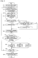
- the details of the instruction to supply power to the remote controller will be described with reference to the flowchart.
- the user When setting up the indoor unit 1, the user allocates the address using the address allocation unit 14 provided in the indoor unit 1 (step S11). More specifically, the user manipulates the dip switch to specify the address of each indoor unit according to a predetermined rule. As mentioned above, the addresses of the indoor units 1 a to 1 d are set to 01 to 04, respectively.
- the outdoor unit 2 then checks the address of all the indoor units 1 for each of which the address has been allocated, via the signal line 4 (step S12). More specifically, the outdoor unit 2 transmits an own address request from the indoor unit address detection unit 25 of the outdoor unit 2 to the indoor units 1 a to 1d, in order to detect the address of all the indoor units connected via the signal line 4. Upon receipt of the own address request from the outdoor unit 2, the indoor units 1 a to 1 d each return an own address response to the outdoor unit 2, so that the outdoor unit 2 acquires the respective addresses of the indoor units 1 a to 1 d and finishes the address detection.
- the remote controller power supply instruction unit 22 of the outdoor unit 2 transmits a remote controller power supply instruction to the indoor unit 1 a which has the lowest number among the detected addresses (step S13).
- the indoor unit 1a causes the remote controller power supply unit 15 to supply power to the remote controller 3a (step S14).
- the remote controller 3a which is receiving the power supply transmits a control data monitor request from the monitor request transmission unit 32 to the indoor units 1 a and 1 b, in order to display the control data such as the operation status of the air-conditioning apparatus, on the displayer 35 (step S15).
- the indoor unit 1 a having the address of the lowest number Upon receipt of the control data monitor request through the monitor request reception unit 16 (Yes at step S16), the indoor unit 1 a having the address of the lowest number stores information to the effect that the request has been received, in the non-volatile memory 18 (step S17).
- the indoor unit 1 b causes the monitor request reception supervision unit 17 to monitor whether other indoor units connected via the same signal line (in this case, indoor unit 1 a) have received the control data monitor request, and upon confirming such reception (Yes at step S18) the indoor unit 1 b stores information to the effect that the indoor unit 1a has received the request, in the non-volatile memory 18 (step S19).
- the outdoor unit 2 transmits a monitor request reception inquiry from the monitor request reception confirmation unit 23 to all the indoor units 1a to 1d connected via the signal line 4 a predetermined time after the transmission of the power supply instruction to the indoor unit 1a having the address of the lowest number, to check whether the indoor units 1 have received the control data monitor request from the remote controller 3 (step S20).
- the indoor unit 1 a transmits a monitor request reception response to the outdoor unit 2.
- the indoor unit 1 b transmits a response indicating other indoor unit's reception of monitor request, to the outdoor unit 2 (step S21).
- the outdoor unit 2 determines that the indoor units 1 a and 1 b which have responded to the monitor request reception inquiry are in the same group, and stores such information in the non-volatile memory 26. At this point, the outdoor unit 2 stores, in the non-volatile memory 26, information to the effect that the indoor unit 1 a, which has transmitted the monitor request reception response, is designated as parent unit that supplies power to the remote controller 3, and that the indoor unit 1 b, which has transmitted the response of other indoor unit's reception of monitor request is designated as child unit that follows the control operation of the parent unit without supplying power to the remote controller (step S22).
- the remote controller power supply instruction unit 22 of the outdoor unit 2 again transmits the power supply instruction to the indoor unit 1c having the address of the lowest number between the indoor units 1 c and 1 d remained after excluding the indoor units 1 a and 1 b belonging to the different group.
- the outdoor unit 2 repeats the mentioned operation until the grouping of all the indoor units connected via the signal line 4 is determined (step S23).
- the outdoor unit 2 Upon completion of the grouping of all the indoor units 1 a to 1 d, the outdoor unit 2 transmits the remote controller power supply instruction to the parent indoor unit of each group (in this case, 1 a and 1 c).
- the parent indoor units 1 a and 1 c which have received the remote controller power supply instruction respectively supply power to the remote controllers 3a and 3b from the remote controller power supply unit 15, and at this point the setting up of the remote controllers 3a and 3b connected to the respective groups is completed (step S24).
- the outdoor unit 2 recognizes the grouping status of the indoor units 1 by making inquiries to the indoor units 1, and the outdoor unit 2 instructs the indoor unit 1 having the address of the lowest number in each group to supply power to the remote controller 3, on the basis of the result of the inquiries.
- Such an arrangement eliminates the need to provide a power supply detection circuit in the indoor unit, thereby enabling reduction in manufacturing cost of the air-conditioning apparatus.
- Embodiment 2 represents a method to continue the power supply to the remote controller by switching the indoor unit that serves as power source, in the case where the parent indoor unit of the group has failed and can no longer supply power to the remote controller.
- Fig. 3 is a flowchart for explaining a remote controller power supply method according to Embodiment 2.
- the remote controller power supply supervision unit 24 of the outdoor unit 2 periodically transmits a power supply status inquiry to the parent indoor units (in this case, 1a and 1c), to thereby monitor the power supply status from the parent indoor units to the respective remote controllers 3 (step S31).
- the parent indoor unit 1 a or 1 c transmits a power supply status response to the outdoor unit, as long as the power supply to the remote controller 3a or 3b is maintained. In case that the power supply from the parent indoor unit is discontinued, the power supply status response is no longer transmitted to the outdoor unit 2 (No at step S32), and hence the outdoor unit 2 recognizes that the power supply from the parent indoor unit 1 a or 1 c to the remote controller 3a or 3b has been discontinued (step S33).
- the outdoor unit 2 retains the addresses of the indoor units 1a to 1d in the groups 10a and 10b, in the non-volatile memory 26.
- the outdoor unit 2 retrieves the addresses of the indoor units 1 a to 1 d from the non-volatile memory 26, and identifies the indoor unit having the address of a second lowest number next to the parent unit (in this case, 1 b or 1 d) in the group 10a or 10b, in whichever the power supply to the remote controller has been discontinued, in order to continue with the power supply to the remote controller 3a or 3b.
- the outdoor unit 2 transmits, from the remote controller power supply instruction unit 22, the remote controller power supply instruction to the indoor unit 1 b or 1 d (step S34).
- the indoor unit 1 b or 1d Upon receipt of the remote controller power supply instruction, the indoor unit 1 b or 1d supplies power to the remote controller 3a or 3b through the remote controller power supply unit 15, to thereby continue the power supply to the remote controller 3a or 3b (step S35).
- the power source is switched to the normal indoor unit 1 b or 1 d having the address of the second lowest number next to the parent unit in the group 10a or 10b, and thus the power supply to the remote controller 3a or 3b can be continued.
- the outdoor unit 2 transmits, in view of the discontinuation of the power supply status response from the parent indoor unit 1 a or 1 c, the remote controller power supply instruction to the indoor unit 1 b or 1 d having the address of the second lowest number next to the parent indoor unit, the outdoor unit 2 transmits at the same time the information that the parent indoor unit can no longer supply power, to the remote controller 3a or 3b through the indoor unit 1 b or 1 d, and causes the remote controller 3a or 3b to display the information to the effect that the remote controller power supply unit 15 of the parent indoor unit has failed, on the displayer 35.
- Such an arrangement allows the user of the air-conditioning apparatus to recognize that the remote controller power supply unit of the parent indoor unit is out of order.
- 1a to 1d indoor unit
- 2 outdoor unit
- 3a, 3b remote controller
- 4, 5a, 5b signal line
- 10a, 10b group, 13, 21, 31: controller
- 14 address allocation unit
- 18, 26 non-volatile memory
- 35 displayer
Landscapes
- Engineering & Computer Science (AREA)
- General Engineering & Computer Science (AREA)
- Mechanical Engineering (AREA)
- Combustion & Propulsion (AREA)
- Chemical & Material Sciences (AREA)
- Physics & Mathematics (AREA)
- Signal Processing (AREA)
- Fuzzy Systems (AREA)
- Mathematical Physics (AREA)
- Human Computer Interaction (AREA)
- Automation & Control Theory (AREA)
- General Physics & Mathematics (AREA)
- Radar, Positioning & Navigation (AREA)
- Electromagnetism (AREA)
- Power Engineering (AREA)
- Health & Medical Sciences (AREA)
- Biomedical Technology (AREA)
- Air Conditioning Control Device (AREA)
Applications Claiming Priority (1)
| Application Number | Priority Date | Filing Date | Title |
|---|---|---|---|
| PCT/JP2013/007437 WO2015092831A1 (fr) | 2013-12-18 | 2013-12-18 | Dispositif de climatisation et procédé d'alimentation de commandes à distance |
Publications (3)
| Publication Number | Publication Date |
|---|---|
| EP3086046A1 true EP3086046A1 (fr) | 2016-10-26 |
| EP3086046A4 EP3086046A4 (fr) | 2017-08-23 |
| EP3086046B1 EP3086046B1 (fr) | 2019-11-20 |
Family
ID=53402227
Family Applications (1)
| Application Number | Title | Priority Date | Filing Date |
|---|---|---|---|
| EP13899476.9A Not-in-force EP3086046B1 (fr) | 2013-12-18 | 2013-12-18 | Dispositif de climatisation et procédé d'alimentation de commandes à distance |
Country Status (4)
| Country | Link |
|---|---|
| US (1) | US10120400B2 (fr) |
| EP (1) | EP3086046B1 (fr) |
| JP (1) | JP6029775B2 (fr) |
| WO (1) | WO2015092831A1 (fr) |
Families Citing this family (10)
| Publication number | Priority date | Publication date | Assignee | Title |
|---|---|---|---|---|
| US10082309B2 (en) * | 2015-01-19 | 2018-09-25 | Lennox Industries Inc. | Server integration with a heating, ventilation, and air conditioning system |
| WO2017212545A1 (fr) * | 2016-06-07 | 2017-12-14 | 三菱電機株式会社 | Climatiseur et procédé de réglage de groupe |
| CN106101299B (zh) * | 2016-06-20 | 2019-07-09 | 海信(山东)空调有限公司 | 室内机地址分配方法和多联机系统 |
| JP6877583B2 (ja) * | 2017-12-12 | 2021-05-26 | 三菱電機株式会社 | リモートコントローラおよび空気調和装置 |
| CN108592302B (zh) * | 2018-04-13 | 2021-04-30 | 珠海格力电器股份有限公司 | 数据的发送方法,装置,多联机系统,存储介质 |
| CN108662718B (zh) * | 2018-04-13 | 2020-07-14 | 珠海格力电器股份有限公司 | 空调器的组网方法和装置 |
| DE112018007982B4 (de) * | 2018-09-14 | 2026-01-15 | Mitsubishi Electric Corporation | Klimatisierungssystem |
| CN112524746B (zh) * | 2019-09-17 | 2021-11-26 | 青岛海尔空调电子有限公司 | 多联机空调系统中室外机均衡结霜的控制方法 |
| WO2021095125A1 (fr) * | 2019-11-12 | 2021-05-20 | 三菱電機株式会社 | Unité extérieure, système de climatisation et programme |
| CN111271811B (zh) * | 2020-01-13 | 2021-08-31 | 宁波奥克斯电气股份有限公司 | 一种空调分组控制方法、模块、空调器及可读存储介质 |
Family Cites Families (9)
| Publication number | Priority date | Publication date | Assignee | Title |
|---|---|---|---|---|
| CN1050659C (zh) * | 1993-04-28 | 2000-03-22 | 达金工业株式会社 | 用于空调器的驱动控制装置 |
| JPH0755238A (ja) * | 1993-08-20 | 1995-03-03 | Mitsubishi Electric Corp | 空気調和機の制御装置 |
| JP3320597B2 (ja) * | 1995-11-09 | 2002-09-03 | 三菱電機株式会社 | 空気調和装置 |
| JP2001241738A (ja) * | 2000-03-02 | 2001-09-07 | Sanyo Electric Co Ltd | 冷凍空調装置及びその制御方法 |
| CN1227486C (zh) * | 2000-04-24 | 2005-11-16 | 三洋电机株式会社 | 空调机的通信系统 |
| JP2007218453A (ja) * | 2006-02-14 | 2007-08-30 | Matsushita Electric Ind Co Ltd | 空気調和機制御装置および空気調和機制御方法ならびに空気調和機制御プログラムを記録した記録媒体 |
| JP5258962B2 (ja) * | 2009-03-26 | 2013-08-07 | 三菱電機株式会社 | 冷凍空調装置の情報伝達システム |
| WO2010122640A1 (fr) * | 2009-04-22 | 2010-10-28 | 三菱電機株式会社 | Climatiseur |
| US20130325191A1 (en) * | 2011-02-21 | 2013-12-05 | Mitsubishi Electric Corporation | Air conditioning apparatus and air conditioning system |
-
2013
- 2013-12-18 EP EP13899476.9A patent/EP3086046B1/fr not_active Not-in-force
- 2013-12-18 WO PCT/JP2013/007437 patent/WO2015092831A1/fr not_active Ceased
- 2013-12-18 JP JP2015553232A patent/JP6029775B2/ja not_active Expired - Fee Related
- 2013-12-18 US US15/033,191 patent/US10120400B2/en active Active
Also Published As
| Publication number | Publication date |
|---|---|
| US20160265799A1 (en) | 2016-09-15 |
| JP6029775B2 (ja) | 2016-11-24 |
| JPWO2015092831A1 (ja) | 2017-03-16 |
| WO2015092831A1 (fr) | 2015-06-25 |
| EP3086046B1 (fr) | 2019-11-20 |
| EP3086046A4 (fr) | 2017-08-23 |
| US10120400B2 (en) | 2018-11-06 |
Similar Documents
| Publication | Publication Date | Title |
|---|---|---|
| EP3086046B1 (fr) | Dispositif de climatisation et procédé d'alimentation de commandes à distance | |
| EP2409550B1 (fr) | Procédé de remplacement semi-automatique de ballast | |
| JP6453825B2 (ja) | 操作盤と無線通信を行う制御装置、無線モジュール、及び無線中継器 | |
| US10512145B2 (en) | Lighting system and wireless relay method thereof | |
| US9832846B2 (en) | Electrical apparatus management system | |
| CN101414173B (zh) | 负载控制系统 | |
| JP2021114475A (ja) | 照明システム | |
| EP3157155A1 (fr) | Procédé de commande d'onduleurs | |
| CN110606415A (zh) | 楼层设定系统 | |
| JP6868197B2 (ja) | 照明装置および照明システム | |
| JP6309785B2 (ja) | 無線テレメータシステム及び無線通信装置 | |
| JP2017084180A (ja) | 自動火災報知システム | |
| EP3430840A1 (fr) | Routage audio réparti d'intercommunication sans fil sur ethernet avec synchronisation et itinérance | |
| WO2021233477A1 (fr) | Appareil, système et procédé de communication et de mise en réseau sans fil pour climatiseur, et support | |
| JP5505017B2 (ja) | 照明制御システム | |
| JP7642708B2 (ja) | リモートコントローラ及び照明システム | |
| JP7683062B2 (ja) | 調光器 | |
| JP7709188B2 (ja) | 無線通信システムの設定方法、無線通信システムおよびプログラム | |
| JP2012175413A (ja) | 監視システム | |
| KR20140140780A (ko) | Led 조명 제어 시스템의 자동 주소 지정 장치 및 방법 | |
| JP2016029790A (ja) | 通信システム、通信装置、およびアドレス設定方法 | |
| JP2008258688A (ja) | ネットワークシステム | |
| JPWO2014010089A1 (ja) | システムおよびシステムの制御方法 | |
| JP2007124738A (ja) | 通信システム及びその通信方法 | |
| KR20110113725A (ko) | 무선 조명 제어 장치 |
Legal Events
| Date | Code | Title | Description |
|---|---|---|---|
| PUAI | Public reference made under article 153(3) epc to a published international application that has entered the european phase |
Free format text: ORIGINAL CODE: 0009012 |
|
| 17P | Request for examination filed |
Effective date: 20160617 |
|
| AK | Designated contracting states |
Kind code of ref document: A1 Designated state(s): AL AT BE BG CH CY CZ DE DK EE ES FI FR GB GR HR HU IE IS IT LI LT LU LV MC MK MT NL NO PL PT RO RS SE SI SK SM TR |
|
| AX | Request for extension of the european patent |
Extension state: BA ME |
|
| DAX | Request for extension of the european patent (deleted) | ||
| A4 | Supplementary search report drawn up and despatched |
Effective date: 20170721 |
|
| RIC1 | Information provided on ipc code assigned before grant |
Ipc: F24F 11/00 20060101AFI20170717BHEP Ipc: G05F 1/66 20060101ALI20170717BHEP |
|
| REG | Reference to a national code |
Ref country code: DE Ref legal event code: R079 Ref document number: 602013063254 Country of ref document: DE Free format text: PREVIOUS MAIN CLASS: F24F0011020000 Ipc: F24F0011620000 |
|
| GRAP | Despatch of communication of intention to grant a patent |
Free format text: ORIGINAL CODE: EPIDOSNIGR1 |
|
| STAA | Information on the status of an ep patent application or granted ep patent |
Free format text: STATUS: GRANT OF PATENT IS INTENDED |
|
| RIC1 | Information provided on ipc code assigned before grant |
Ipc: F24F 11/62 20180101AFI20190626BHEP Ipc: F24F 11/30 20180101ALI20190626BHEP Ipc: G05F 1/66 20060101ALI20190626BHEP |
|
| INTG | Intention to grant announced |
Effective date: 20190712 |
|
| GRAS | Grant fee paid |
Free format text: ORIGINAL CODE: EPIDOSNIGR3 |
|
| GRAA | (expected) grant |
Free format text: ORIGINAL CODE: 0009210 |
|
| STAA | Information on the status of an ep patent application or granted ep patent |
Free format text: STATUS: THE PATENT HAS BEEN GRANTED |
|
| AK | Designated contracting states |
Kind code of ref document: B1 Designated state(s): AL AT BE BG CH CY CZ DE DK EE ES FI FR GB GR HR HU IE IS IT LI LT LU LV MC MK MT NL NO PL PT RO RS SE SI SK SM TR |
|
| REG | Reference to a national code |
Ref country code: GB Ref legal event code: FG4D |
|
| REG | Reference to a national code |
Ref country code: CH Ref legal event code: EP |
|
| REG | Reference to a national code |
Ref country code: DE Ref legal event code: R096 Ref document number: 602013063254 Country of ref document: DE |
|
| REG | Reference to a national code |
Ref country code: IE Ref legal event code: FG4D |
|
| REG | Reference to a national code |
Ref country code: AT Ref legal event code: REF Ref document number: 1204628 Country of ref document: AT Kind code of ref document: T Effective date: 20191215 |
|
| REG | Reference to a national code |
Ref country code: NL Ref legal event code: MP Effective date: 20191120 |
|
| REG | Reference to a national code |
Ref country code: LT Ref legal event code: MG4D |
|
| PG25 | Lapsed in a contracting state [announced via postgrant information from national office to epo] |
Ref country code: SE Free format text: LAPSE BECAUSE OF FAILURE TO SUBMIT A TRANSLATION OF THE DESCRIPTION OR TO PAY THE FEE WITHIN THE PRESCRIBED TIME-LIMIT Effective date: 20191120 Ref country code: LV Free format text: LAPSE BECAUSE OF FAILURE TO SUBMIT A TRANSLATION OF THE DESCRIPTION OR TO PAY THE FEE WITHIN THE PRESCRIBED TIME-LIMIT Effective date: 20191120 Ref country code: GR Free format text: LAPSE BECAUSE OF FAILURE TO SUBMIT A TRANSLATION OF THE DESCRIPTION OR TO PAY THE FEE WITHIN THE PRESCRIBED TIME-LIMIT Effective date: 20200221 Ref country code: NO Free format text: LAPSE BECAUSE OF FAILURE TO SUBMIT A TRANSLATION OF THE DESCRIPTION OR TO PAY THE FEE WITHIN THE PRESCRIBED TIME-LIMIT Effective date: 20200220 Ref country code: FI Free format text: LAPSE BECAUSE OF FAILURE TO SUBMIT A TRANSLATION OF THE DESCRIPTION OR TO PAY THE FEE WITHIN THE PRESCRIBED TIME-LIMIT Effective date: 20191120 Ref country code: LT Free format text: LAPSE BECAUSE OF FAILURE TO SUBMIT A TRANSLATION OF THE DESCRIPTION OR TO PAY THE FEE WITHIN THE PRESCRIBED TIME-LIMIT Effective date: 20191120 Ref country code: BG Free format text: LAPSE BECAUSE OF FAILURE TO SUBMIT A TRANSLATION OF THE DESCRIPTION OR TO PAY THE FEE WITHIN THE PRESCRIBED TIME-LIMIT Effective date: 20200220 Ref country code: NL Free format text: LAPSE BECAUSE OF FAILURE TO SUBMIT A TRANSLATION OF THE DESCRIPTION OR TO PAY THE FEE WITHIN THE PRESCRIBED TIME-LIMIT Effective date: 20191120 |
|
| PG25 | Lapsed in a contracting state [announced via postgrant information from national office to epo] |
Ref country code: RS Free format text: LAPSE BECAUSE OF FAILURE TO SUBMIT A TRANSLATION OF THE DESCRIPTION OR TO PAY THE FEE WITHIN THE PRESCRIBED TIME-LIMIT Effective date: 20191120 Ref country code: IS Free format text: LAPSE BECAUSE OF FAILURE TO SUBMIT A TRANSLATION OF THE DESCRIPTION OR TO PAY THE FEE WITHIN THE PRESCRIBED TIME-LIMIT Effective date: 20200320 Ref country code: HR Free format text: LAPSE BECAUSE OF FAILURE TO SUBMIT A TRANSLATION OF THE DESCRIPTION OR TO PAY THE FEE WITHIN THE PRESCRIBED TIME-LIMIT Effective date: 20191120 |
|
| PG25 | Lapsed in a contracting state [announced via postgrant information from national office to epo] |
Ref country code: AL Free format text: LAPSE BECAUSE OF FAILURE TO SUBMIT A TRANSLATION OF THE DESCRIPTION OR TO PAY THE FEE WITHIN THE PRESCRIBED TIME-LIMIT Effective date: 20191120 |
|
| PG25 | Lapsed in a contracting state [announced via postgrant information from national office to epo] |
Ref country code: PT Free format text: LAPSE BECAUSE OF FAILURE TO SUBMIT A TRANSLATION OF THE DESCRIPTION OR TO PAY THE FEE WITHIN THE PRESCRIBED TIME-LIMIT Effective date: 20200412 Ref country code: EE Free format text: LAPSE BECAUSE OF FAILURE TO SUBMIT A TRANSLATION OF THE DESCRIPTION OR TO PAY THE FEE WITHIN THE PRESCRIBED TIME-LIMIT Effective date: 20191120 Ref country code: RO Free format text: LAPSE BECAUSE OF FAILURE TO SUBMIT A TRANSLATION OF THE DESCRIPTION OR TO PAY THE FEE WITHIN THE PRESCRIBED TIME-LIMIT Effective date: 20191120 Ref country code: DK Free format text: LAPSE BECAUSE OF FAILURE TO SUBMIT A TRANSLATION OF THE DESCRIPTION OR TO PAY THE FEE WITHIN THE PRESCRIBED TIME-LIMIT Effective date: 20191120 Ref country code: ES Free format text: LAPSE BECAUSE OF FAILURE TO SUBMIT A TRANSLATION OF THE DESCRIPTION OR TO PAY THE FEE WITHIN THE PRESCRIBED TIME-LIMIT Effective date: 20191120 Ref country code: CZ Free format text: LAPSE BECAUSE OF FAILURE TO SUBMIT A TRANSLATION OF THE DESCRIPTION OR TO PAY THE FEE WITHIN THE PRESCRIBED TIME-LIMIT Effective date: 20191120 |
|
| REG | Reference to a national code |
Ref country code: CH Ref legal event code: PL |
|
| REG | Reference to a national code |
Ref country code: AT Ref legal event code: MK05 Ref document number: 1204628 Country of ref document: AT Kind code of ref document: T Effective date: 20191120 |
|
| REG | Reference to a national code |
Ref country code: DE Ref legal event code: R097 Ref document number: 602013063254 Country of ref document: DE |
|
| REG | Reference to a national code |
Ref country code: BE Ref legal event code: MM Effective date: 20191231 |
|
| PG25 | Lapsed in a contracting state [announced via postgrant information from national office to epo] |
Ref country code: SM Free format text: LAPSE BECAUSE OF FAILURE TO SUBMIT A TRANSLATION OF THE DESCRIPTION OR TO PAY THE FEE WITHIN THE PRESCRIBED TIME-LIMIT Effective date: 20191120 Ref country code: SK Free format text: LAPSE BECAUSE OF FAILURE TO SUBMIT A TRANSLATION OF THE DESCRIPTION OR TO PAY THE FEE WITHIN THE PRESCRIBED TIME-LIMIT Effective date: 20191120 Ref country code: MC Free format text: LAPSE BECAUSE OF FAILURE TO SUBMIT A TRANSLATION OF THE DESCRIPTION OR TO PAY THE FEE WITHIN THE PRESCRIBED TIME-LIMIT Effective date: 20191120 |
|
| PLBE | No opposition filed within time limit |
Free format text: ORIGINAL CODE: 0009261 |
|
| STAA | Information on the status of an ep patent application or granted ep patent |
Free format text: STATUS: NO OPPOSITION FILED WITHIN TIME LIMIT |
|
| 26N | No opposition filed |
Effective date: 20200821 |
|
| PG25 | Lapsed in a contracting state [announced via postgrant information from national office to epo] |
Ref country code: LU Free format text: LAPSE BECAUSE OF NON-PAYMENT OF DUE FEES Effective date: 20191218 Ref country code: IE Free format text: LAPSE BECAUSE OF NON-PAYMENT OF DUE FEES Effective date: 20191218 Ref country code: FR Free format text: LAPSE BECAUSE OF NON-PAYMENT OF DUE FEES Effective date: 20200120 |
|
| PG25 | Lapsed in a contracting state [announced via postgrant information from national office to epo] |
Ref country code: SI Free format text: LAPSE BECAUSE OF FAILURE TO SUBMIT A TRANSLATION OF THE DESCRIPTION OR TO PAY THE FEE WITHIN THE PRESCRIBED TIME-LIMIT Effective date: 20191120 Ref country code: AT Free format text: LAPSE BECAUSE OF FAILURE TO SUBMIT A TRANSLATION OF THE DESCRIPTION OR TO PAY THE FEE WITHIN THE PRESCRIBED TIME-LIMIT Effective date: 20191120 Ref country code: CH Free format text: LAPSE BECAUSE OF NON-PAYMENT OF DUE FEES Effective date: 20191231 Ref country code: PL Free format text: LAPSE BECAUSE OF FAILURE TO SUBMIT A TRANSLATION OF THE DESCRIPTION OR TO PAY THE FEE WITHIN THE PRESCRIBED TIME-LIMIT Effective date: 20191120 Ref country code: BE Free format text: LAPSE BECAUSE OF NON-PAYMENT OF DUE FEES Effective date: 20191231 Ref country code: LI Free format text: LAPSE BECAUSE OF NON-PAYMENT OF DUE FEES Effective date: 20191231 |
|
| PG25 | Lapsed in a contracting state [announced via postgrant information from national office to epo] |
Ref country code: IT Free format text: LAPSE BECAUSE OF FAILURE TO SUBMIT A TRANSLATION OF THE DESCRIPTION OR TO PAY THE FEE WITHIN THE PRESCRIBED TIME-LIMIT Effective date: 20191120 |
|
| PG25 | Lapsed in a contracting state [announced via postgrant information from national office to epo] |
Ref country code: CY Free format text: LAPSE BECAUSE OF FAILURE TO SUBMIT A TRANSLATION OF THE DESCRIPTION OR TO PAY THE FEE WITHIN THE PRESCRIBED TIME-LIMIT Effective date: 20191120 |
|
| PG25 | Lapsed in a contracting state [announced via postgrant information from national office to epo] |
Ref country code: MT Free format text: LAPSE BECAUSE OF FAILURE TO SUBMIT A TRANSLATION OF THE DESCRIPTION OR TO PAY THE FEE WITHIN THE PRESCRIBED TIME-LIMIT Effective date: 20191120 Ref country code: HU Free format text: LAPSE BECAUSE OF FAILURE TO SUBMIT A TRANSLATION OF THE DESCRIPTION OR TO PAY THE FEE WITHIN THE PRESCRIBED TIME-LIMIT; INVALID AB INITIO Effective date: 20131218 |
|
| PG25 | Lapsed in a contracting state [announced via postgrant information from national office to epo] |
Ref country code: TR Free format text: LAPSE BECAUSE OF FAILURE TO SUBMIT A TRANSLATION OF THE DESCRIPTION OR TO PAY THE FEE WITHIN THE PRESCRIBED TIME-LIMIT Effective date: 20191120 |
|
| PG25 | Lapsed in a contracting state [announced via postgrant information from national office to epo] |
Ref country code: MK Free format text: LAPSE BECAUSE OF FAILURE TO SUBMIT A TRANSLATION OF THE DESCRIPTION OR TO PAY THE FEE WITHIN THE PRESCRIBED TIME-LIMIT Effective date: 20191120 |
|
| REG | Reference to a national code |
Ref country code: DE Ref legal event code: R084 Ref document number: 602013063254 Country of ref document: DE |
|
| REG | Reference to a national code |
Ref country code: GB Ref legal event code: 746 Effective date: 20230103 |
|
| P01 | Opt-out of the competence of the unified patent court (upc) registered |
Effective date: 20230512 |
|
| PGFP | Annual fee paid to national office [announced via postgrant information from national office to epo] |
Ref country code: GB Payment date: 20231102 Year of fee payment: 11 |
|
| PGFP | Annual fee paid to national office [announced via postgrant information from national office to epo] |
Ref country code: DE Payment date: 20231031 Year of fee payment: 11 |
|
| REG | Reference to a national code |
Ref country code: DE Ref legal event code: R119 Ref document number: 602013063254 Country of ref document: DE |
|
| GBPC | Gb: european patent ceased through non-payment of renewal fee |
Effective date: 20241218 |
|
| PG25 | Lapsed in a contracting state [announced via postgrant information from national office to epo] |
Ref country code: DE Free format text: LAPSE BECAUSE OF NON-PAYMENT OF DUE FEES Effective date: 20250701 |
|
| PG25 | Lapsed in a contracting state [announced via postgrant information from national office to epo] |
Ref country code: GB Free format text: LAPSE BECAUSE OF NON-PAYMENT OF DUE FEES Effective date: 20241218 |