EP3086074A1 - Rohrelement und wärmetauscher - Google Patents
Rohrelement und wärmetauscher Download PDFInfo
- Publication number
- EP3086074A1 EP3086074A1 EP15164827.6A EP15164827A EP3086074A1 EP 3086074 A1 EP3086074 A1 EP 3086074A1 EP 15164827 A EP15164827 A EP 15164827A EP 3086074 A1 EP3086074 A1 EP 3086074A1
- Authority
- EP
- European Patent Office
- Prior art keywords
- tubular element
- tube
- segments
- manifold
- wall
- Prior art date
- Legal status (The legal status is an assumption and is not a legal conclusion. Google has not performed a legal analysis and makes no representation as to the accuracy of the status listed.)
- Withdrawn
Links
- 239000012530 fluid Substances 0.000 claims abstract description 28
- 238000005192 partition Methods 0.000 claims description 12
- 239000007788 liquid Substances 0.000 claims description 3
- 238000005219 brazing Methods 0.000 description 7
- 239000003507 refrigerant Substances 0.000 description 7
- 238000001816 cooling Methods 0.000 description 5
- 239000000463 material Substances 0.000 description 4
- 238000004519 manufacturing process Methods 0.000 description 3
- 238000004080 punching Methods 0.000 description 2
- 230000005494 condensation Effects 0.000 description 1
- 238000009833 condensation Methods 0.000 description 1
- 238000010438 heat treatment Methods 0.000 description 1
- 239000002245 particle Substances 0.000 description 1
- 238000005057 refrigeration Methods 0.000 description 1
Images


Classifications
-
- F—MECHANICAL ENGINEERING; LIGHTING; HEATING; WEAPONS; BLASTING
- F28—HEAT EXCHANGE IN GENERAL
- F28F—DETAILS OF HEAT-EXCHANGE AND HEAT-TRANSFER APPARATUS, OF GENERAL APPLICATION
- F28F9/00—Casings; Header boxes; Auxiliary supports for elements; Auxiliary members within casings
- F28F9/02—Header boxes; End plates
- F28F9/0202—Header boxes having their inner space divided by partitions
- F28F9/0204—Header boxes having their inner space divided by partitions for elongated header box, e.g. with transversal and longitudinal partitions
- F28F9/0209—Header boxes having their inner space divided by partitions for elongated header box, e.g. with transversal and longitudinal partitions having only transversal partitions
-
- F—MECHANICAL ENGINEERING; LIGHTING; HEATING; WEAPONS; BLASTING
- F28—HEAT EXCHANGE IN GENERAL
- F28D—HEAT-EXCHANGE APPARATUS, NOT PROVIDED FOR IN ANOTHER SUBCLASS, IN WHICH THE HEAT-EXCHANGE MEDIA DO NOT COME INTO DIRECT CONTACT
- F28D1/00—Heat-exchange apparatus having stationary conduit assemblies for one heat-exchange medium only, the media being in contact with different sides of the conduit wall, in which the other heat-exchange medium is a large body of fluid, e.g. domestic or motor car radiators
- F28D1/02—Heat-exchange apparatus having stationary conduit assemblies for one heat-exchange medium only, the media being in contact with different sides of the conduit wall, in which the other heat-exchange medium is a large body of fluid, e.g. domestic or motor car radiators with heat-exchange conduits immersed in the body of fluid
- F28D1/04—Heat-exchange apparatus having stationary conduit assemblies for one heat-exchange medium only, the media being in contact with different sides of the conduit wall, in which the other heat-exchange medium is a large body of fluid, e.g. domestic or motor car radiators with heat-exchange conduits immersed in the body of fluid with tubular conduits
- F28D1/053—Heat-exchange apparatus having stationary conduit assemblies for one heat-exchange medium only, the media being in contact with different sides of the conduit wall, in which the other heat-exchange medium is a large body of fluid, e.g. domestic or motor car radiators with heat-exchange conduits immersed in the body of fluid with tubular conduits the conduits being straight
- F28D1/05316—Assemblies of conduits connected to common headers, e.g. core type radiators
- F28D1/05325—Assemblies of conduits connected to common headers, e.g. core type radiators with particular pattern of flow, e.g. change of flow direction
-
- F—MECHANICAL ENGINEERING; LIGHTING; HEATING; WEAPONS; BLASTING
- F28—HEAT EXCHANGE IN GENERAL
- F28F—DETAILS OF HEAT-EXCHANGE AND HEAT-TRANSFER APPARATUS, OF GENERAL APPLICATION
- F28F9/00—Casings; Header boxes; Auxiliary supports for elements; Auxiliary members within casings
- F28F9/02—Header boxes; End plates
- F28F9/0219—Arrangements for sealing end plates into casing or header box; Header box sub-elements
- F28F9/0224—Header boxes formed by sealing end plates into covers
-
- F—MECHANICAL ENGINEERING; LIGHTING; HEATING; WEAPONS; BLASTING
- F28—HEAT EXCHANGE IN GENERAL
- F28F—DETAILS OF HEAT-EXCHANGE AND HEAT-TRANSFER APPARATUS, OF GENERAL APPLICATION
- F28F9/00—Casings; Header boxes; Auxiliary supports for elements; Auxiliary members within casings
- F28F9/02—Header boxes; End plates
- F28F9/0243—Header boxes having a circular cross-section
-
- F—MECHANICAL ENGINEERING; LIGHTING; HEATING; WEAPONS; BLASTING
- F28—HEAT EXCHANGE IN GENERAL
- F28F—DETAILS OF HEAT-EXCHANGE AND HEAT-TRANSFER APPARATUS, OF GENERAL APPLICATION
- F28F2275/00—Fastening; Joining
- F28F2275/04—Fastening; Joining by brazing
- F28F2275/045—Fastening; Joining by brazing with particular processing steps, e.g. by allowing displacement of parts during brazing or by using a reservoir for storing brazing material
Definitions
- the invention refers to a tubular element for a heat exchanger, especially for a condenser for a refrigeration cycle of a motor vehicle, in accordance with the preamble of claim 1.
- the invention relates additionally to a heat exchanger.
- Heat exchanger and especially condenser are well known in the state of the art especially for the use in motor vehicles.
- Condensers are used as heat exchanger in a refrigerant circuit condensing the refrigerant and usually additionally sub-cooling the liquified refrigerant before it flows to the expansion valve and the evaporator of the refrigerant circuit.
- the condenser provides two separated manifolds and between the manifolds tubes and fins are located, the tubes are usually arranged in a row of tubes between which the respective fins are located.
- the tubes are fluid connected to the interior of the manifolds since the tubes are fit in openings of the respective tubes. Therefore the refrigerant can flow through the fluid passages of tubes of the row of tubes from one manifold to the other manifold being cooled by way of a heat exchange with the air flow flowing around the tubes.
- Such condensers are known e.g. by DE 41 30 517 A1 , DE 43 30 214 A1 or DE 43 39 952 A1 .
- the manifolds are usually produced as a single tube or as a tube in a two part design.
- the known single-part design uses an extruded tube or a welded or brazed in which openings are provided by punching such that tubes of the row of tubes can be located within the openings and are fluid tight connected by to the manifold by brazing.
- the known two-part design uses a bottom plate including the openings for fitting the tubes in the openings and a cover plate connected to the bottom plate. The bottom plate and the cover plate are fluid tight connected by brazing.
- Such a manifold is disclosed by DE 43 39 952 A1 .
- the condenser is provided with a number of fluid paths while the refrigerant flows through the different flow paths one after the other.
- the first flow path usually is a de-heating flow path and the last flow path usually is a sub-cooling flow path, while intermediate flow paths are used as condensation paths.
- the different flow paths are created by tubes of the row of tubes which are separated by partition walls which are inserted in the manifolds at respective positions within the manifolds. Such a design is well known and disclosed e.g. by DE 43 39 952 A1 .
- condenser modules which additionally provide a receiver and/or dryer tube in parallel with one of the manifolds.
- condenser modules have the advantage that the sub-cooling is advanced since the sub-cooling path is usually completely filled with liquid refrigerant which is additionally cooled by the air flowing around the tubes and fins of the sub-cooling flow path.
- condenser modules are known from DE 42 38 853 C2 .
- the problem addressed with regard to this invention is to create a heat exchanger, especially for a motor vehicle, which allows a less expensive manufacture.
- a preferred embodiment relates to a tubular element for a heat exchanger, especially for a motor vehicle, which is assembled by stacking first tube-shaped segments and second cup-shaped segments along the length direction of the tubular element, wherein the assembled first and second segments are fluid tight connected, wherein closed upper and lower ends of the tubular element are achieved by using second cup-shaped segments. Therefore the tubular element can be assembled using an amount of first and/or second segments such that the respective design can be achieved using almost only generally designed segments and the amount of especially designed segments is reduced. This leads to a cost effective manufacture of a tubular element.
- At least one partition wall or partition walls which are located within the tubular element is or are created by using at least one second cup-shaped segment.
- a first tube-shaped segment has a tube wall and a first opening at a first end of the tube wall and a second opening at a second end of the tube wall. Therefore partition walls can easily be integrated within the tubular element by using cup-shaped segments which otherwise can be used e.g. as closure at the upper or lower end of the tubular element.
- An embodiment of the tubular element is designed such that a second cup-shaped segment has a tube wall and a first opening at a first end of the tube wall and a closing wall at a second end of the tube wall. Therefore the cup-shaped segment provides a tube body with one opening and with one closure at one of their respective ends.
- the tube wall of a first segment and/or of a second segment has a reduced outer diameter at one of the first end or the second end, such that an outer diameter of the end with the reduced diameter is smaller than an inner diameter of the end without a reduced diameter or with a smaller reduction in diameter.
- openings are provided in first tube-shaped segments and/or second cup-shaped segments, wherein the openings are provided to receive tube ends of tubes of a tube block of a heat exchanger. Accordingly a fluid tight connection of a tube block can be achieved if the tube ends are located in openings of
- a further embodiment is of a tubular element is designed such that openings are provided in first tube-shaped segments and/or second cup-shaped segments, wherein the openings are provided as liquid transfer openings through which a fluid is transferrable between different devices. Therefore the tubular element can be used as receiver of a condenser or a condenser module or the like.
- tubular element a design is preferred wherein the tube wall has a circular cross-section or a circular cross-section having a flattened portion. Therefore the flattened portion or a part of a circular portion can be used as location for an opening which can be created e.g. by punching. Furthermore the tubular element can be designed such that it is of advantage that the openings are provided in the tube wall in an area having the circular cross-section or in an area of the flattened portion.
- the tubular element is a manifold of a heat exchanger, especially of a condenser. Therefore the tubular element can be designed and assembled as manifold without or with partition walls. Such partition walls maybe used as guiding elements to direct a fluid flow and to divide a tube block in different flow paths.
- the tubular element is a receiver of a heat exchanger, especially of a condenser module having a condenser and a receiver.
- the object of the invention may be achieved by a heat exchanger with at least one manifold, especially with two manifolds and with a tube block with tubes which are fluid-tight connected to the at least one manifold, wherein the at least one manifold is an inventive manifold.
- the object of the invention may additionally be achieved by a heat exchanger with at least one manifold, especially with two manifolds and with a tube block with tubes which are fluid-tight connected to the at least one manifold, with a receiver fluid tight connected to a manifold, wherein the receiver is an inventive receiver.
- FIG. 1 shows a part of a heat exchanger 10 with a first embodiment of a tubular element 1, which may be used as manifold 11 of the heat exchanger 10.
- a heat exchanger 10 is may be manufactured as a condenser or as a radiator or the like.
- the tubular element 1 comprises a plurality of first segments 2 and/or second segments 3, which are stacked and connected in length direction of the tubular element 1.
- Figure 1 shows an upper part 4 of the tubular element 1 with four second segments 3 and two first segments 2, while the lower part 5 may comprise at least one second segment 3 as can be seen.
- the upper segment 6 and the lower segment 7 are made as second segments 3 while intermediate segments are made as first segments 2 or second segments 3 respectively.
- the first segments 2 are made as tube-shaped segments.
- the tube-shaped segments comprise a tubular wall 9 with a first opening 12 at a first end 13 and with a second opening 14 at a second end 15. Therefore a fluid may flow through the both openings 12, 14 and through the tube which is defined by the tubular wall 9.
- second segments with a predetermined length such that are pre-manufactured and selected from a system of second segments. Otherwise at least one second segment can be manufactured with a certain length to fit to the overall length of the tubular element 1.
- the second segments 3 are made as cup-shaped segments.
- the cup-shaped segments comprise a tubular wall 16 with a first opening 17 at a first end 18 and with a closing wall 19 at a second end 20. Therefore a fluid may flow through the one first opening 17 into the tube made by the tube wall but can not flow through the complete tube since the closing wall 19 limits the flow at the second end 20.
- closing wall 19 of the second segment 3 might be used as closure wall at the upper and lower end of the tubular element and e.g. as partition wall 21 within the tubular element 1.
- the tubular wall 9 or 16 of the first segment or of the second segment has a reduced outer diameter d at one of the first end or the second end, such that an outer diameter of the end with the reduced diameter d is smaller than an inner diameter of the end without a reduced diameter having a diameter D.
- This connection will be fluid tight connected such as brazed.
- the tubular element 1 is designed as manifold and comprises openings 22 which are provided in first tube-shaped segments 2 and in the second cup-shaped segments 3.
- the openings 22 are located such the tube ends 23 of tubes 24 of a tube block 25 might be located in the openings 22. Therefore the tubes 24 can communicate with the inner space of the manifold.
- the cross section 26 of a first and/or of a second segment or the respective tubbular wall 9, 16 has a circular cross-section 27 having a flattened portion 28.
- the flattened portion 28 is preferred to place the openings 22 and e.g. punch the openings in the tube wall.
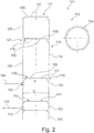
- FIG. 2 shows a part of a second embodiment of a tubular element 101, which may be used as receiver 111 of the heat exchanger 110.
- a heat exchanger 110 is may be manufactured as a condenser or as a radiator or the like.
- the tubular element 101 comprises a plurality of first segments and/or second segments 103, which are stacked and connected in length direction of the tubular element 101.
- Figure 2 shows an upper part 104 of the tubular element 101 with five second segments 103, while the lower part may comprise at least one first segment or one second segment.
- the upper segment 106 and the not shown lower segment are made as second segments 103 while intermediate segments 108 are made as first segments or second segments respectively.
- the first segments are made as tube-shaped segments.
- the tube-shaped segments comprise a tubular wall with a first opening at a first end and with a second opening at a second end, as can be seen from Figure 1 . Therefore a fluid may flow through the both openings and through the tube which is defined by the tubular wall of the first segment.
- second segments with a predetermined length such that are pre-manufactured and selected from a system of second segments. Otherwise at least one second segment can be manufactured with a certain length to fit to the overall length of the tubular element 1.
- the second segments 103 are made as cup-shaped segments.
- the cup-shaped segments comprise a tubular 116 wall with a first opening 117 at a first end 118 and with a closing wall 119 at a second end 120. Therefore a fluid may flow through the one opening 117 into the tube made by the tube wall but can not flow through the complete tube since the closing wall 119 limits the flow at the second end 120.
- closing wall 119 of the second segment 103 might be used as closure wall at the upper and lower end of the tubular element and e.g. as partition wall within the tubular element 101.
- a perforated closing wall 119 allowing a through flow and therefore only named as perforated wall 119 can be used to locate a dryer material between two of such perforated walls 119.
- a perforated wall 119 might be used as filter in case the holes 150 are small in diameter such that particles might be filtered out of the fluid flow by means of the perforated wall 119.
- the wall 151 is used as filter and the walls 152 and 153 are used to define the space for a dryer material between them.
- the tube wall 116 of a first segment or of the shown second segment 103 has a reduced outer diameter d at one of the first end or the second end, such that an outer diameter of the end with the reduced diameter d is smaller than an inner diameter of the end without a reduced diameter having a diameter D.
- This connection will be fluid tight connected such as brazed.
- the tubular element 101 is designed as receiver and comprises openings 122, 123 which are provided in two second segments 103.
- the openings 122 and 123 allow an inflow 124 and an outflow 125 of a fluid into the receiver or out of the receiver.
- the cross section 126 of a first and/or of a second segment or the respective tube wall 116 has a circular cross-section. Other shapes are possible too.
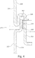
- FIGS. 3 and 4 show different embodiments of a connection between two segments of a first segment and/or a second segment.
- Figure 3 shows a segment 201 and a segment 202 wherein the segment 201 maybe a first or second segment and segment 202 maybe a first segment or a second segment. Only a part of the two segments are shown to explain the connection between the two segments 201, 202.
- Both segments have a tubular wall 203, 204, while segment 201 has an end 205 with a reduced diameter d and segment 202 has an end 206 without a reduced diameter having the diameter D with D > d.
- a brazing material 208 like a brazing ring might be located to fluid tightly braze and connect the two walls 203 and 204 at their ends 205, 206.
- a functional gap 209 remains between the both ends of the segments 201 and 202. According to this connection concept a secure and fluid tight connection can be achieved.
- Figure 3 shows that the diameter reduction of the end 205 of segment 201 is realised by a step to reduce the diameter from the diameter of the tubular wall 203 to the diameter of the end 205. This might be realised by deep drawing or other deformation of the wall or the like.
- Figure 4 shows a segment 301 and a segment 302 wherein the segment 301 maybe a first or second segment and segment 302 maybe a first segment or a second segment. Only a part of the two segments 301 and 302 are shown to explain the connection concept to connect the two segments 301, 302.
- Both segments 301, 302 have a tubular wall 303, 304, while segment 301 has an end 205 with a reduced diameter d and segment 302 has an end 306 without such a reduced diameter having the diameter D with D > d.
- the outer diameter of the end 305 is smaller than the inner diameter of the end 306 such that the end 305 fits in the inner space of the end 306.
- Figure 4 shows that the diameter reduction of the end 305 of segment 301 is realised by a s-shaped step to reduce the diameter from the diameter of the tubular wall 303 to the diameter of the end 305.
- a ring-shaped space 307 is provided to receive the end 306 of the other segment 302.
- the end 306 shows a reduction in diameter to fit in the space 307.
- a brazing material 309 like a brazing ring might be located to fluid tightly braze and connect the two walls 303 and 304 at their ends 305, 306.
- a functional gap 310 remains in the axial direction between the both ends 305, 306 of the segments 301 and 302. According to this connection concept a secure and fluid tight connection can be achieved.
Landscapes
- Engineering & Computer Science (AREA)
- Physics & Mathematics (AREA)
- Thermal Sciences (AREA)
- Mechanical Engineering (AREA)
- General Engineering & Computer Science (AREA)
- Heat-Exchange Devices With Radiators And Conduit Assemblies (AREA)
Priority Applications (1)
| Application Number | Priority Date | Filing Date | Title |
|---|---|---|---|
| EP15164827.6A EP3086074A1 (de) | 2015-04-23 | 2015-04-23 | Rohrelement und wärmetauscher |
Applications Claiming Priority (1)
| Application Number | Priority Date | Filing Date | Title |
|---|---|---|---|
| EP15164827.6A EP3086074A1 (de) | 2015-04-23 | 2015-04-23 | Rohrelement und wärmetauscher |
Publications (1)
| Publication Number | Publication Date |
|---|---|
| EP3086074A1 true EP3086074A1 (de) | 2016-10-26 |
Family
ID=53039240
Family Applications (1)
| Application Number | Title | Priority Date | Filing Date |
|---|---|---|---|
| EP15164827.6A Withdrawn EP3086074A1 (de) | 2015-04-23 | 2015-04-23 | Rohrelement und wärmetauscher |
Country Status (1)
| Country | Link |
|---|---|
| EP (1) | EP3086074A1 (de) |
Cited By (1)
| Publication number | Priority date | Publication date | Assignee | Title |
|---|---|---|---|---|
| EP3385654A1 (de) * | 2017-04-05 | 2018-10-10 | Denso Marston Ltd. | Verteiler für einen wärmetauscher |
Citations (9)
| Publication number | Priority date | Publication date | Assignee | Title |
|---|---|---|---|---|
| EP0325452A1 (de) * | 1988-01-22 | 1989-07-26 | Sanden Corporation | Wärmeaustauscher |
| DE4130517A1 (de) | 1991-09-13 | 1993-03-18 | Behr Gmbh & Co | Anschlusskasten fuer einen waermetauscher, insbesondere fuer einen kaeltemittelkondensator |
| DE4330214A1 (de) | 1993-09-07 | 1995-03-09 | Behr Gmbh & Co | Wärmetauscher |
| DE4339952A1 (de) | 1993-11-24 | 1995-06-01 | Behr Gmbh & Co | Wärmetauscher mit mehreren parallelen Flachrohren |
| DE4238853C2 (de) | 1992-11-18 | 2001-05-03 | Behr Gmbh & Co | Kondensator für eine Klimaanlage eines Fahrzeuges |
| US20020023743A1 (en) * | 2000-07-03 | 2002-02-28 | Jung Jong Dae | Head assembly of heat exchanger for vehicle |
| US6729386B1 (en) * | 2001-01-22 | 2004-05-04 | Stanley H. Sather | Pulp drier coil with improved header |
| EP1471323A2 (de) * | 2003-03-31 | 2004-10-27 | Calsonic Kansei Corporation | Sammlerrohr für Wärmetauscher |
| WO2010139485A2 (de) * | 2009-06-06 | 2010-12-09 | Geoclimadesign Ag | Rohrstück und daraus gebildete kapillarrohrmatte |
-
2015
- 2015-04-23 EP EP15164827.6A patent/EP3086074A1/de not_active Withdrawn
Patent Citations (9)
| Publication number | Priority date | Publication date | Assignee | Title |
|---|---|---|---|---|
| EP0325452A1 (de) * | 1988-01-22 | 1989-07-26 | Sanden Corporation | Wärmeaustauscher |
| DE4130517A1 (de) | 1991-09-13 | 1993-03-18 | Behr Gmbh & Co | Anschlusskasten fuer einen waermetauscher, insbesondere fuer einen kaeltemittelkondensator |
| DE4238853C2 (de) | 1992-11-18 | 2001-05-03 | Behr Gmbh & Co | Kondensator für eine Klimaanlage eines Fahrzeuges |
| DE4330214A1 (de) | 1993-09-07 | 1995-03-09 | Behr Gmbh & Co | Wärmetauscher |
| DE4339952A1 (de) | 1993-11-24 | 1995-06-01 | Behr Gmbh & Co | Wärmetauscher mit mehreren parallelen Flachrohren |
| US20020023743A1 (en) * | 2000-07-03 | 2002-02-28 | Jung Jong Dae | Head assembly of heat exchanger for vehicle |
| US6729386B1 (en) * | 2001-01-22 | 2004-05-04 | Stanley H. Sather | Pulp drier coil with improved header |
| EP1471323A2 (de) * | 2003-03-31 | 2004-10-27 | Calsonic Kansei Corporation | Sammlerrohr für Wärmetauscher |
| WO2010139485A2 (de) * | 2009-06-06 | 2010-12-09 | Geoclimadesign Ag | Rohrstück und daraus gebildete kapillarrohrmatte |
Cited By (1)
| Publication number | Priority date | Publication date | Assignee | Title |
|---|---|---|---|---|
| EP3385654A1 (de) * | 2017-04-05 | 2018-10-10 | Denso Marston Ltd. | Verteiler für einen wärmetauscher |
Similar Documents
| Publication | Publication Date | Title |
|---|---|---|
| US20020066553A1 (en) | Heat exchanger and method for producing a heat exchanger | |
| EP2977706B1 (de) | Verteiler und wärmetauscher damit | |
| EP2927631B1 (de) | Wärmetauscher, insbesondere Kondensator | |
| US8959948B2 (en) | Receiver dryer | |
| JPH04254171A (ja) | レシーバドライヤ一体型コンデンサ | |
| US20050279125A1 (en) | Integrated condenser/receiver and insert for use therein | |
| JP2010175241A (ja) | 2種類の流体のための熱交換器、特に空調装置のための蓄積蒸発器 | |
| US10337808B2 (en) | Condenser | |
| JP6816160B2 (ja) | 自動車両空調設備の熱交換器用のタンクを充填するための充填チューブを有する相変化材料のタンク | |
| HK1204358A1 (en) | Heat exchanger utilizing tubular structures having internal flow altering members and external chamber assemblies | |
| JP2015200478A (ja) | コンデンサ | |
| US5946938A (en) | Condenser with a separate reservoir for an air conditioning installation, especially for motor vehicles | |
| WO2010082535A1 (ja) | 熱交換器 | |
| US20160231067A1 (en) | Heat exchanger with clam-shell header | |
| EP3086074A1 (de) | Rohrelement und wärmetauscher | |
| EP2960613B1 (de) | Sammler für einen Wärmetauscher und damit ausgestatteter Wärmetauscher, insbesondere Kondensator | |
| US20020157814A1 (en) | Heat exchanger header and tank unit | |
| JP2009276011A (ja) | 受液器一体型凝縮器 | |
| JP2008267753A (ja) | 熱交換器 | |
| EP2743607A2 (de) | Unterkühlter Kondensator mit einem Empfängerbehälter mit einem Kältemittelumlenker für verbesserte Füllungseffizienz | |
| JP2007078292A (ja) | 熱交換器および複式熱交換器 | |
| US20060070724A1 (en) | Integrated receiver dryer sleeve | |
| EP3541645B1 (de) | Kondensator für eine klimaanlage, insbesondere für ein kraftfahrzeug | |
| EP2784425B1 (de) | Wärmetauscher, insbesondere Kondensator | |
| JP6133573B2 (ja) | 受液器付き熱交換器 |
Legal Events
| Date | Code | Title | Description |
|---|---|---|---|
| PUAI | Public reference made under article 153(3) epc to a published international application that has entered the european phase |
Free format text: ORIGINAL CODE: 0009012 |
|
| AK | Designated contracting states |
Kind code of ref document: A1 Designated state(s): AL AT BE BG CH CY CZ DE DK EE ES FI FR GB GR HR HU IE IS IT LI LT LU LV MC MK MT NL NO PL PT RO RS SE SI SK SM TR |
|
| AX | Request for extension of the european patent |
Extension state: BA ME |
|
| STAA | Information on the status of an ep patent application or granted ep patent |
Free format text: STATUS: THE APPLICATION IS DEEMED TO BE WITHDRAWN |
|
| 18D | Application deemed to be withdrawn |
Effective date: 20170427 |