EP3086100A1 - Doppelseitige waage - Google Patents
Doppelseitige waage Download PDFInfo
- Publication number
- EP3086100A1 EP3086100A1 EP16164212.9A EP16164212A EP3086100A1 EP 3086100 A1 EP3086100 A1 EP 3086100A1 EP 16164212 A EP16164212 A EP 16164212A EP 3086100 A1 EP3086100 A1 EP 3086100A1
- Authority
- EP
- European Patent Office
- Prior art keywords
- additional
- weighing
- weighing surface
- load cells
- balance
- Prior art date
- Legal status (The legal status is an assumption and is not a legal conclusion. Google has not performed a legal analysis and makes no representation as to the accuracy of the status listed.)
- Granted
Links
Images
Classifications
-
- G—PHYSICS
- G01—MEASURING; TESTING
- G01G—WEIGHING
- G01G21/00—Details of weighing apparatus
- G01G21/22—Weigh pans or other weighing receptacles; Weighing platforms
-
- G—PHYSICS
- G01—MEASURING; TESTING
- G01G—WEIGHING
- G01G21/00—Details of weighing apparatus
- G01G21/23—Support or suspension of weighing platforms
-
- G—PHYSICS
- G01—MEASURING; TESTING
- G01G—WEIGHING
- G01G21/00—Details of weighing apparatus
- G01G21/28—Frames, Housings
-
- G—PHYSICS
- G01—MEASURING; TESTING
- G01G—WEIGHING
- G01G23/00—Auxiliary devices for weighing apparatus
-
- G—PHYSICS
- G01—MEASURING; TESTING
- G01G—WEIGHING
- G01G23/00—Auxiliary devices for weighing apparatus
- G01G23/18—Indicating devices, e.g. for remote indication; Recording devices; Scales, e.g. graduated
- G01G23/36—Indicating the weight by electrical means, e.g. using photoelectric cells
- G01G23/37—Indicating the weight by electrical means, e.g. using photoelectric cells involving digital counting
Definitions
- the invention relates to a balance with a support plate, which is supported by load cells on a substrate and whose upper side forms a weighing surface on which a first load to be weighed can be placed, an additional weighing surface, which is supported by additional load cells on a substrate and on the one weighing second load can be placed with an electronics, which is able to determine the weight of the load from a measuring signal supplied by the load cells or the additional load cells and with a display device for displaying the weight determined by the electronics.
- Scales of this type are manufactured by Bakdo B.V. on the Internet at the URL (http://www.ideascomfort.de/de/kuche/kuchenutensilien/zweiflachige-waage/2635316.html) offered.
- a housing is provided, which has on its upper side the support plate with the weighing surface.
- the support plate is supported by feet on the housing, wherein the load cells are interposed and are deflected by the resting on the support plate weight.
- the well-known Libra is a kitchen scale.
- the measuring range of kitchen trolleys is usually between 0 and a few kilograms, in the case of the above-mentioned scale, the maximum is 5000 g.
- the reason for this restriction is the sensitivity of the load cells, since only sensitive load cells offer a sufficiently low resolution.
- Kitchen scales usually have a resolution of 1-2 g. Depending on the application, this resolution may be too inaccurate, so that then there is the desire for a higher resolution.
- the disadvantage of the known balance is that on the one hand a housing must be provided that receives the drawer. This limits the design options the Libra.
- the drawer is a mechanical component that is just in the non-clean kitchen environment exposed to a certain contamination and can be operated only comparatively complicated.
- a further disadvantage is that the user is presented with both path surfaces when the drawer is pulled out, so that he may not even use the fine weighing section, but unknowingly weighs the small weight with the large weighing surface.
- an erroneously still outstanding drawer with the sensitive weighing unit can be overloaded by an excessive load and thus damaged.
- the object of the invention is therefore to provide a balance that has two weighing functions, but is inexpensive to produce and easy to use.
- the additional weighing surface is arranged below the weighing surface and for weighing the on the additional weighing surface loadable in the direction of the weighing surface, wherein the display device is designed such that it is readable in a first weighing mode in which the weighing surface is oriented upwards, and a second weighing mode in which the additional weighing surface is oriented upwards.
- the inventive design of the balance can now easily be switched back and forth between the two weighing functions.
- the additional weighing surface is arranged. This means that the scale is simply turned through 180 ° in order to use the other weighing device.
- the scales according to the invention can have any function.
- the invention is not limited to the use as a kitchen scale. Also, the invention is not limited to that the resolution and the measuring range of the two weighing devices combined in the new scale are different.
- the balance has a second additional weighing surface.
- the balance is designed in such a way that the additional weighing surface can be used after rotating the balance by 180 °. This means that the additional weighing surface is moved during weighing in the direction opposite to the direction of movement of the weighing surface of the main scale direction. If the main scale is used, the additional weighing surface hangs inactive on the underside of the scale.
- the main scale During operation of the main scale, there will preferably be no contact between the additional weighing surface and the base forming the footprint for the main scale. Otherwise, a frictional connection will be generated that falsifies the measurement result of the main scale. In the worst case, the additional load cells could also be damaged if the weight of the load resting on the weighing surface were completely transferred to the additional load cells. This means that due to the lack of contact of the additional weighing surface with the footprint the main scale can be used in this orientation like a standard scale.
- the indicator also displays the weight of the load on the weighing surface as with any other balance.
- the display device may be provided below the weighing surface, so that the user can read the weight value through the weighing surface, which is then formed in this area as a viewing window.
- the display device may also be provided on the edge of the weighing surface.
- Kitchen cars usually have a housing, on the upper side of the weighing surface is provided.
- the load cells can be provided between the support plate with the weighing surface and the housing, alternatively, the housing can be supported on feet on the footprint, wherein the load cells can then be provided between the feet and the housing.
- Bathroom trolleys on the other hand, often also have a design without a separate housing, in which case the electronics are provided with a support plate and connected via electrical connections to the load cells and also to the support plate arranged display device.
- the load cells in turn are integrated in this embodiment in feet whose upper portion is connected at the corners with the support plate.
- the embodiment according to the invention with the second additional weighing surface arranged below the support plate can be implemented in conjunction with both embodiments.
- the housing may either have feet that are high enough to give the additional weighing surface sufficient space on the underside of the housing.
- the housing may also have a pocket-like depression, within which the additional weighing surface is arranged.
- downwardly projecting spacers can be provided, which sit on a contact surface of the additional weighing surface with the substrate on the ground and thus protect the sensitive additional load cells.
- the bag-like Recess can also be closed by a sliding closure or a flap.
- the housing could also upwards, laterally on the support plate with the weighing surface guided by carrying elements that still protrude above and act as a stand when rotated balance, in which then the additional load cells are integrated.
- the second scale would work and be constructed in the same way as the first scale.
- this would have the disadvantage that the dimensions of the load to be weighed with the weighing surface of the main scale is limited, since these may not rest even these support elements.
- the additional weighing surface can be arranged directly on spacers of at the bottom of the weighing surface of the main scale supporting support plate. These spacers are then formed in two parts and each connected to the additional load cell. This means that the weighing surface rests on the substrate when the balance is reversed. The back of the support surface carrying the weighing surface then functionally forms the footprint for the additional balance.
- the load cells of the main scale are in this case upwards and are not burdened by a weight which is placed on the additional weighing surface, since this is smaller than the distance of the load cells of the main scale from each other.
- the display device according to the invention is designed so that it can be read even with turned scale. This can be done in different ways. On the one hand can be arranged on the support plate, the display device, which is readable in an upward-oriented weighing surface through a viewing window in the support plate. This display device may have a second display that is readable from below and is read when the additional function is used in weighing over the additional weighing surface with turned scale.
- a common display can be used, which can be read with a display from both sides. So that the display does not appear mirrored when the scale is turned, an orientation sensor can be provided indicating to the electronics whether the additional weighing surface is pointing up the weighing surface, so that the display is adapted to this.
- the orientation sensor may also be used by the electronics to selectively interrogate the measurement signal of the load cells or the additional load cells. This energy can be saved, so that the standby time of the scale can be increased. Furthermore, via the orientation sensor, then without switching off the load cells, can be switched from a weighing mode in an error correction mode. If the electronics receive a signal from the upwardly protruding load cells, this is interpreted as meaning that the load on the additional weighing surface also rests on these load cells, so that a faulty measurement can be expected. In this case, then in the display device no measurement result, but an error message is displayed.
- the readability of the display device with turned scale can finally be realized via a rotatable display device which is rotatably mounted either on the support plate or on a housing, if this is available.
- the display device is designed as a separate component from the other parts of the scale, which receives the necessary information for displaying the court value by radio or other wireless data transmission connection from the balance.
- the power supply of the balance is preferably via batteries or an accumulator. In both cases, the power supply can be used for both weighing functions. If several displays are present, the power supply can also supply both displays with power. Alternatively, of course, a second power supply can be provided, so that in principle two independent scales are present, the smaller scale is attached to the underside of the larger scale.
- the measuring range of the main scale designed as a kitchen scale may, for example, be between 0 and 10,000 g, the resolution of a preferred embodiment being 1 g.
- the fine scale, which is rotated 180 ° underneath can then have a measuring range between 0 and 500 g, the resolution here is 0.1 g.
- This example illustrates that the scale according to the invention also allows combinations of uses, for example, the main scale can be used as a kitchen scale, while the underlying, finer scale can be used as a medicine or spice scales, letter scale or other scale.
- Another application for the balance according to the invention may also be a personal scale.
- the main scale can be used to weigh heavyweight people, while the underlying, higher-resolution additional scale can be used for children, infants or even light-weight people.
- a personal scale can be created, which can also be used for obese people, without the other household members would have to give up the higher resolution.
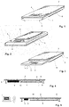
- FIG. 1 is a possible embodiment of the balance according to the invention shown using a kitchen scale.
- the balance has a housing 1, on the upper side of which a support plate with a weighing surface 2 is arranged. Integrated into the weighing surface 2 is a viewing window, through which a display 4 of a display device 4 can be read.
- the additional weighing surface 5 is shown below the housing 1, below the additional weighing surface 5 is shown.
- This additional weighing surface 5 is, like the weighing surface 2, arranged on the housing 1 and is supported on not shown here additional load cells 8 on the housing 1, when the housing 1 is rotated by 180 °.
- the support plate with the weighing surface 2 in turn is supported by load cells 3, wherein in the illustrated embodiment, the support plate is fixedly connected to the housing 1 and the load cells 3 are arranged in small feet over which the housing 1 rests on a standing surface.
- the feet have the allowable advantage that they extend beyond the level of the additional weighing surface 5 so far that they prevent at the same time in the case of FIG. 1 illustrated orientation of the scale whose maximum load the additional weighing surface 5 come into contact with the base.
- FIG. 2 shows the in FIG. 1 illustrated embodiment of the balance in a rotated position by 180 °. It can be seen that now the support plate rests with the weighing surface 2 on the base. The feet with the load cells 3 now protrude substantially vertically upward and are functionally in terms of weighing. Now, the active surface is the additional weighing surface 5.
- the display device 4 is here visible from both sides, the balance via an orientation switch, the display is able to switch so that it does not appear mirrored but can be read by the user.
- FIG. 3 shows another embodiment of the balance.
- the weighing surface 2, the housing 1 and the additional weighing surface 5 are of similar construction here as in the embodiment illustrated in FIGS. 1 and 2. However, here the display device 4 is provided around the rotation axis D rotatable at the front portion of the housing 1.
- FIG. 4 illustrates the basic structure of a third embodiment of a balance according to the invention.
- This embodiment is particularly often used in conjunction with passenger cars.
- the display 4 of the display device is provided below the support plate.
- the support plate with the weighing surface 2 has for this purpose at this point a first viewing window 6. Through this viewing window 6, the user can read the weight value displayed by the display device 4.
- the electronics 9 is housed in a housing which is arranged directly on the underside of the support plate.
- the electronics 9 is connected via electrical connections 10 to the load cells 2, the additional load cells 8 and a power supply, not shown here. Of course, this power supply can also be integrated in the electronics 9.
- the electrical connections 10 extend under the support plate in the form of electrical lines in small, glued to the support plate channels.
- a second scale is now mounted under the support plate.
- This second scale consists of an additional weighing surface 5, which is attached to feet that protrude up here and where the additional weighing surface 5 is attached hanging. Additional load cells 8 are integrated in these feet.
- the additional load cells 8 have a smaller measuring range than the weighing cells 2 and have a higher resolution.
- the user turns the scale as described above.
- the determined weight value can then be read through the second viewing window 7.
- the display device 4 may also be provided outside the area covered by the additional weighing surface 5, when the weighing surface 2 is large enough. In this case, of course, can then be dispensed with the second viewing window 7.
- FIG. 4 a fourth embodiment of a balance according to the invention, which differs from the preceding embodiments in that the display device 4 is formed as a separate component, which is able to communicate via wireless connection to the electronics 9. In this case, the Users can read the display in a proven way regardless of the orientation of the scale.
- the balance takes place in the embodiments described here by the user himself.
- the balance is easy to turn over.
- the balance can also be arranged a central holder on which it is pivotally or rotatably mounted.
- This holder can also be designed as a wall mounting device, so that the balance is, for example, at right angles protruding from a wall and is rotatably mounted on the holder.
- the balance is preferably provided with a housing 1, as in the embodiment according to the Figures 1-3 the case is.
- the housing 1 may be connected via a rotary connection with the wall holder.
- the wall holder may also have the display device 4 at the same time.
- the display device 4 is attached directly to the wall. So that it can be read off better here is preferably the display device 4 is tilted and facing the user.
Landscapes
- Physics & Mathematics (AREA)
- General Physics & Mathematics (AREA)
- Devices For Indicating Variable Information By Combining Individual Elements (AREA)
- Details Of Rigid Or Semi-Rigid Containers (AREA)
Abstract
Description
- Die Erfindung betrifft eine Waage mit einer Tragplatte, die sich über Wägezellen auf einem Untergrund abstützt und deren Oberseite eine Wägefläche bildet, auf die eine zu wiegende erste Last auflegbar ist, einer Zusatzwägefläche, die sich über Zusatzwägezellen auf einem Untergrund abstützt und auf die eine zu wiegende zweite Last auflegbar ist, mit einer Elektronik, die aus einem von den Wägezellen oder den Zusatzwägezellen gelieferten Messsignal das Gewicht der Last zu bestimmen vermag und mit einer Anzeigevorrichtung zum Anzeigen des von der Elektronik ermittelten Gewichts.
- Waagen dieser Art werden von der Firma Bakdo B.V. im Internet unter der URL (http://www.ideascomfort.de/de/kuche/kuchenutensilien/zweiflachige-waage/2635316.html) angeboten. Bei diesen Waagen ist ein Gehäuse vorgesehen, das auf seiner Oberseite die Tragplatte mit der Wägefläche aufweist. Die Tragplatte stützt sich über Standfüsse auf dem Gehäuse ab, wobei die Wägezellen zwischengeschaltet sind und durch das auf der Tragplatte aufliegenden Gewicht ausgelenkt werden.
- Die bekannte Waage ist eine Küchenwaage. Der Messbereich von Küchenwagen beträgt üblicherweise zwischen 0 und einigen Kilogramm, bei der oben genannten Waage sind es maximal 5000 g. Grund für diese Einschränkung ist die Empfindlichkeit der Wägezellen, da nur empfindliche Wägezellen eine hinreichend kleine Auflösung bieten. Küchenwaagen haben dabei üblicherweise eine Auflösung von 1-2 g. Je nach Anwendungsfall kann diese Auflösung zu ungenau sein, so dass dann der Wunsch nach einer höheren Auflösung vorliegt. Dies realisiert die bekannte Küchenwaage durch eine zweite Waage, die in einer Schublade im Gehäuse angeordnet ist. Diese zweite Feinwaage weist empfindlicherer Dehnungsmeßstreifen auf, hat dafür jedoch im Gegenzug nur eine geringere maximale Belastbarkeit.
- Der Nachteil der bekannten Waage besteht darin, dass zum einen ein Gehäuse vorgesehen sein muss, dass die Schublade aufnimmt. Dies schränkt die Gestaltungsmöglichkeiten der Waage ein. Darüber hinaus ist die Schublade ein mechanisches Bauteil, das gerade in der nicht sauberen Küchenumgebung einer gewissen Verschmutzung ausgesetzt ist und nur vergleichsweise kompliziert bedient werden kann. Ein weiterer Nachteil besteht darin, dass dem Benutzer beide Wegeflächen bei herausgezogener Schublade präsentiert werden, so dass er den Feinwiegebereich möglicherweise gar nicht benutzt, sondern unwissentlich das kleine Gewicht mit der großen Wiegefläche abwiegt. Schließlich kann eine irrtümlich noch herausragende Schublade mit der empfindlichen Wiegeeinheit durch eine zu hohe Belastung überlastet und damit beschädigt werden.
- Aus der
CN 2 03 323 855 U ist eine Waage mit zwei Tragplatten als Wiegeflächen auf der Oberseite bekannt. Die beiden Tragplatten sind über Meßwertaufnehmer gelagert, die unterschiedliche Messbereiche und Messgenauigkeiten aufweisen. Eine ähnliche Ausgestaltung ist aus derJP S58-61 418 A JP S58-61 418 A - Aus der
DE 10 2010 033 143 A1 ist eine Waage bekannt, bei der zwei Kraftaufnehmer in Reihe geschaltet sind. Diese Waage hat zwar den Vorteil, dass über die beiden Kraftmesser unterschiedliche Nennlasten und damit unterschiedliche Messbereiche und Messgenauigkeiten gewogen werden können, jedoch ist die Reihenschaltung hinsichtlich der Eindeutigkeit der Wiegefunktion und der Bahuhöhe nachteilig. - Aufgabe der Erfindung ist es daher, eine Waage zu schaffen, die über zwei Wiegefunktionen verfügt, aber kostengünstig herstellbar und leicht zu bedienen ist.
- Diese Aufgabe wird nach der Erfindung dadurch gelöst, dass die Zusatzwägefläche unterhalb der Wägefläche angeordnet ist und zum Wiegen des auf der Zusatzwägefläche aufliegenden Gewichts in Richtung der Wägefläche belastbar ist, wobei die Anzeigevorrichtung derart ausgebildet ist, dass sie in einem ersten Wiegemodus, in dem die Wägefläche nach oben orientiert ist, und einem zweiten Wiegemodus, in dem die Zusatzwägefläche nach oben orientiert ist, ablesbar ist.
- Durch die erfindungsgemäße Ausgestaltung der Waage kann nun zwischen den beiden Wiegefunktionen ganz einfach hin und her gewechselt werden. An der Unterseite der Waage ist die Zusatzwägefläche angeordnet. Dies bedeutet, dass die Waage einfach um 180° gewendet wird, um die jeweils andere Wiegevorrichtung benutzen zu können.
- Die erfindungsgemäßen Waagen können jede Funktion aufweisen. Die Erfindung ist nicht auf die Anwendung als Küchenwaage beschränkt. Auch ist die Erfindung nicht darauf beschränkt, dass die Auflösung und der Messbereich der beiden, in der neuen Waage kombinierten Wiegevorrichtungen unterschiedlich sind.
- Im Folgenden wird die Erfindung anhand einer Küchenwaage mit Zusatzwiegefunktion beschrieben. In gleicher Weise lassen sich aber auch Personenwaagen, Briefwaagen oder sonstige Waagen mit der zweiten Funktion ergänzen.
- Die Waage weist unterhalb der Tragplatte, deren Oberfläche die Wägefläche für die Hauptwaage bildet, eine zweite Zusatzwägefläche auf. Dabei ist die Waage so konstruiert, dass die Zusatzwägefläche nach Drehen der Waage um 180° benutzt werden kann. Dies bedeutet, dass die Zusatzwägefläche beim Wiegen in die zur Bewegungsrichtung der Wägefläche der Hauptwaage entgegengesetzte Richtung bewegt wird. Wird die Hauptwaage verwendet, hängt die Zusatzwägefläche inaktiv an der Unterseite der Waage.
- Während des Betriebes der Hauptwaage wird bevorzugt kein Kontakt zwischen der Zusatzwägefläche und dem die Stellfläche für die Hauptwaage bildenden Untergrund vorliegen. Ansonsten wird ein Kraftschluss erzeugt werden, der das Messergebnis der Hauptwaage verfälscht. Schlimmstenfalls könnten auch die Zusatzwägezellen beschädigt werden, wenn sich das Gewicht, der auf der Wägefläche aufliegenden Last vollständig auf die Zusatzwägezellen übertragen würde. Dies bedeutet, dass aufgrund des fehlenden Kontaktes der Zusatzwägefläche mit der Stellfläche die Hauptwaage in dieser Orientierung wie eine übliche Waage verwendet werden kann. Die Anzeigevorrichtung zeigt das Gewicht der auf der Wägefläche liegenden Last wie bei jeder anderen Waage auch an.
- Die Anzeigevorrichtung kann unterhalb der Wägefläche vorgesehen sein, sodass der Benutzer den Gewichtswert durch die Wägefläche hindurch ablesen kann, die in diesem Bereich dann als Sichtfenster ausgebildet ist. Alternativ kann die Anzeigevorrichtung auch am Rand der Wägefläche vorgesehen sein.
- Grundsätzlich sind derzeit zwei grundsätzlich unterschiedliche Ausgestaltungen von Waagen üblich: Küchenwagen weisen meist ein Gehäuse auf, auf dessen Oberseite die Wägefläche vorgesehen ist. Dabei können die Wägezellen zwischen der Tragplatte mit der Wägefläche und dem Gehäuse vorgesehen sein, alternativ kann sich das Gehäuse über Standfüsse auf der Stellfläche abstützen, wobei die Wägezellen dann auch zwischen den Standfüssen und dem Gehäuse vorgesehen sein können.
- Badezimmerwagen dagegen weisen häufig auch eine Ausgestaltung ohne separates Gehäuse auf, hier ist dann die Elektronik eine Tragplatte vorgesehen und über elektrische Verbindungen mit den Wägezellen und der ebenfalls an der Tragplatte angeordneten Anzeigevorrichtung verbunden. Die Wägezellen wiederum sind bei dieser Ausgestaltung in Standfüsse integriert, deren oberer Bereich an den Ecken mit der Tragplatte verbunden ist.
- Die erfindungsgemäße Ausgestaltung mit unterhalb der Tragplatte angeordneter zweiter Zusatzwägefläche lässt in Verbindung mit beiden Ausgestaltungen umsetzen. Bei der erstgenannten Ausgestaltung kann das Gehäuse entweder Standfüsse aufweisen, die hoch genug sind, um der Zusatzwägefläche ausreichend Raum auf der Unterseite des Gehäuses einzuräumen.
- Alternativ kann das Gehäuse auch eine taschenartige Einsenkung aufweisen, innerhalb derer die Zusatzwägefläche angeordnet ist. In jedem Fall können neben der Zusatzwägefläche nach unten hervorspringende Distanzhalter vorgesehen sein, die vor einem Kontakt der Zusatzwägefläche mit dem Untergrund auf dem Untergrund aufsetzen und so die empfindlichen Zusatzwägezellen schützen. Die taschenartige Ausnehmung kann auch über einen Schiebeverschluss oder eine Klappe verschlossen werden.
- Schließlich könnte das Gehäuse auch nach oben, seitlich an der Tragplatte mit der Wägefläche vorbeigeführte Tragelemente aufweisen, die noch oben abstehen und bei gedrehter Waage als Standfüsse agieren, in die dann die Zusatzwägezellen integriert sind. Dann würde funktional die zweite Waage auf gleiche Weise arbeiten und aufgebaut sein wie die erste Waage. Dies hätte allerdings den Nachteil, dass die Abmessungen der Last, die mit der Wägefläche der Hauptwaage gewogen werden soll, begrenzt ist, da diese ja nicht auch diesen Tragelementen aufliegen darf.
- Bei der Ausgestaltung der Waage ohne Gehäuse, die auch als Küchenwaage konzeptioniert sein kann, kann dann die Zusatzwägefläche unmittelbar über Distanzstücke von an der Unterseite der die Wägefläche der Hauptwaage tragenden Tragplatte angeordnet sein. Diese Distanzstücke sind dann zweiteilig ausgebildet und jeweils mit der Zusatzwägezelle verbunden. Dies bedeutet, dass bei umgekehrter Waage die Wägefläche auf dem Untergrund aufliegt. Die Rückseite der die Wägefläche tragenden Tragplatte bildet dann funktionell die Standfläche für die zusätzliche Waage. Die Wägezellen der Hauptwaage stehen in diesem Fall nach oben ab und werden durch ein Gewicht, das auf die Zusatzwägefläche aufgelegt wird, nicht belastet, da diese kleiner ist als der Abstand der Wägezellen der Hauptwaage voneinander.
- Die Anzeigevorrichtung ist erfindungsgemäß so ausgebildet, dass sie auch bei gewendeter Waage ablesbar ist. Dies kann auf verschiedene Weise erfolgen. Zum einen kann an der Tragplatte die Anzeigevorrichtung angeordnet sein, die bei nach oben orientierter Wägefläche durch ein Sichtfenster in der Tragplatte ablesbar ist. Diese Anzeigevorrichtung kann ein zweites Display aufweisen, das von unten ablesbar ist und abgelesen wird, wenn die Zusatzfunktion beim Wiegen über die Zusatzwägefläche mit gewendeter Waage genutzt wird.
- Alternativ kann auch ein gemeinsames Display genutzt werden, das mit einer Anzeige von beiden Seiten abgelesen werden kann. Damit bei gewendeter Waage die Anzeige nicht spiegelverkehrt erscheint, kann ein Orientierungssensor vorgesehen sein, der der Elektronik anzeigt, ob die Zusatzwägefläche die Wägefläche nach oben gerichtet ist, so dass die Anzeige hieran angepasst wird.
- Der Orientierungssensor kann ferner von der Elektronik auch genutzt werden, um selektiv das Messsignal der Wägezellen oder der Zusatzwägezellen abzufragen. Hierüber kann Energie gespart werden, so dass sich die Stand-by Zeit der Waage vergrößern lässt. Weiterhin kann über den Orientierungssensor, dann ohne Abschalten der Wägezellen, von einem Wiegemodus in einen Fehlerkorrekturmodus umgeschaltet werden. Empfängt die Elektronik von den nach oben abstehenden Wägezellen ein Signal, wird dies dahingehend interpretiert, dass die Last auf der Zusatzwägefläche auch auf diesen Wägezellen aufliegt, so dass eine Fehlmessung zu erwarten ist. In diesem Fall wird dann in der Anzeigevorrichtung kein Messergebnis, sondern eine Fehlermeldung angezeigt.
- Die Ablesbarkeit der Anzeigevorrichtung bei gewendeter Waage kann schließlich auch über eine drehbare Anzeigevorrichtung realisiert werden, die entweder an der Tragplatte oder an einem Gehäuse, sofern dieses vorhanden ist, drehbar befestigt ist.
- Eine weitere Möglichkeit besteht natürlich darin, dass die Anzeigevorrichtung als von den übrigen Teilen der Waage separates Bauteil ausgebildet ist, das die notwendigen Informationen zum Anzeigen des Gerichtswertes per Funk oder eine sonstige drahtlose Datenübertragungsverbindung von der Waage erhält.
- Die Energieversorgung der Waage erfolgt bevorzugt über Batterien oder einen Akkumulator. In beiden Fällen kann die Energieversorgung für beide Wiegefunktionen genutzt werden. Sind mehrere Displays vorhanden, kann die Energieversorgung auch beide Displays mit Strom versorgen. Alternativ kann natürlich auch eine zweite Energieversorgung vorgesehen sein, so dass im Prinzip zwei voneinander unabhängige Waagen vorliegen, wobei die kleinere Waage an der Unterseite der größeren Waage befestigt ist.
- Der Messbereich der als Küchenwaage ausgebildeten Hauptwaage kann beispielsweise zwischen 0 und 10000 g liegen, wobei die Auflösung eines bevorzugten Ausführungsbeispiels bei 1 g liegt. Die darunter angeordnete, um 180° gedrehte Feinwaage kann dann einen Messbereich zwischen 0 und 500 g aufweisen, die Auflösung beträgt hier 0,1 g. Dieses Beispiel verdeutlicht, dass die erfindungsgemäße Waage auch Kombinationen von Verwendungen erlaubt, so kann zum Beispiel die Hauptwaage als Küchenwaage Verwendung finden, während die darunterliegende, feinere Waage als Arzneimittel oder Gewürzwaage, Briefwaage oder sonstige Waage eingesetzt werden kann.
- Ein weiterer Anwendungsfall für die erfindungsgemäße Waage kann auch eine Personenwaage sein. Hier kann zumal die Hauptwaage zum Wiegen von schwergewichtigen Personen eingesetzt werden, während die darunterliegende, höher auflösende Zusatzwaage für Kinder, Säuglinge oder auch nur leichtgewichtige Personen verwendet werden kann. So kann eine Personenwaage geschaffen werden, die auch für adipöse Menschen verwendet werden kann, ohne dass die übrigen Haushaltsmitglieder auf die höhere Auflösung verzichten müssten.
- Weitere Merkmale und Vorteile der Erfindung ergeben sich der nachfolgenden Beschreibung bevorzugter Ausführungsbeispiele anhand der Zeichnungen.
- In den Zeichnungen zeigt:
- Fig. 1
- eine erfindungsgemäße Waage in schematischer Ansicht,
- Fig. 2
- die in
Figur 1 dargestellte, umgedrehte Waage - Fig. 3
- eine weitere Ausgestaltung einer erfindungsgemäßen Waage,
- Fig. 4
- eine dritte Ausgestaltung einer erfindungsgemäßen Waage und
- Fig. 5
- eine vierte Ausgestaltung einer erfindungsgemäßen Waage.
- In
Figur 1 ist eine mögliche Ausgestaltung der erfindungsgemäßen Waage anhand einer Küchenwaage dargestellt. Die Waage weist ein Gehäuse 1 auf, auf deren Oberseite eine Tragplatte mit einer Wägefläche 2 angeordnet ist. Integriert in die Wägefläche 2 ist ein Sichtfenster, durch das ein Display 4 einer Anzeigevorrichtung 4 ablesbar ist. - Unterhalb des Gehäuses 1 ist die Zusatzwägefläche 5 dargestellt. Diese Zusatzwägefläche 5 ist, wie die Wägefläche 2, am Gehäuse 1 angeordnet und stützt sich über hier nicht dargestellte Zusatzwägezellen 8 auf dem Gehäuse 1 ab, wenn das Gehäuse 1 um 180° gedreht wird. Die Tragplatte mit der Wägefläche 2 wiederum stützt sich über Wägezellen 3 ab, wobei im gezeigten Ausführungsbeispiel die Tragplatte fest mit dem Gehäuse 1 verbunden ist und die Wägezellen 3 in kleinen Standfüssen angeordnet sind, über die das Gehäuse 1 auf einer Standfläche aufsteht. Die Standfüsse haben den zulässigen Vorteil, dass sie die Ebene der Zusatzwägefläche 5 soweit überragen, dass sie gleichzeitig verhindern, dass im Falle der in
Figur 1 dargestellten Orientierung der Waage dessen maximaler Belastung die Zusatzwägefläche 5 mit der Standfläche in Kontakt kommen. -
Figur 2 zeigt die inFigur 1 dargestellte Ausgestaltung der Waage in einer um 180° gedrehten Stellung. Zu erkennen ist, dass nun die Tragplatte mit der Wägefläche 2 auf der Standfläche aufliegt. Die Standfüße mit den Wägezellen 3 ragen nun im Wesentlichen vertikal nach oben und sind hinsichtlich der Wiegefunktion funktionslos. Nun ist die aktive Fläche die Zusatzwägefläche 5. Die Anzeigevorrichtung 4 ist hier von beiden Seiten aus sichtbar, wobei die Waage über ein Orientierungsschalter die Anzeige so umzuschalten vermag, dass sie nicht spiegelverkehrt erscheint sondern vom Benutzer abgelesen werden kann. - Zu erkennen ist in
Figur 2 insbesondere Tatsache, dass die Zusatzwägefläche 5 kleiner als die Wägefläche 2 ist. Die Standfüsse, die die Wägezellen 3 aufnehmen, überragen die Zusatzwägefläche 5, sind aber weit genug von ihr entfernt, so dass auch etwas größere Lasten auf die Zusatzwägefläche 5 aufgelegt werden können. -
Figur 3 zeigt eine andere Ausgestaltung der Waage. Die Wägefläche 2, das Gehäuse 1 und die Zusatzwägefläche 5 sind hier ähnlich aufgebaut wie bei der in den Figuren 1 und 2 dargestellten Ausführungsform. Allerdings ist hier die Anzeigevorrichtung 4 um die Drehachse D drehbar am vorderen Bereich des Gehäuses 1 vorgesehen. - In den
Figuren 4 und 5 sind mögliche Ausgestaltungen der Erfindung schematisch dargestellt.Figur 4 verdeutlicht den grundsätzlichen Aufbau einer dritten Ausgestaltung einer erfindungsgemäßen Waage. Bei dieser Ausgestaltung ist kein Gehäuse 1 vorgesehen. Vielmehr stützt sich die Tragplatte mit der Wägefläche 2 unmittelbar über Standfüsse, in die die Wägezellen 3 integriert sind, auf der Standfläche ab. Diese Ausgestaltung wird besonders häufig in Verbindung mit Personenwagen verwendet. - Das Display 4 der Anzeigevorrichtung ist unterhalb der Tragplatte vorgesehen. Die Tragplatte mit der Wägefläche 2 weist hierzu an dieser Stelle ein erstes Sichtfenster 6 auf. Durch dieses Sichtfenster 6 kann der Benutzer den von der Anzeigevorrichtung 4 angezeigten Gewichtswert ablesen. Die Elektronik 9 ist in einem Gehäuse untergebracht, das unmittelbar an der Unterseite der Tragplatte angeordnet ist. Die Elektronik 9 ist über elektrische Verbindungen 10 mit den Wägezellen 2, den Zusatzwägezellen 8 und einer hier nicht dargestellten Energieversorgung verbunden. Diese Energieversorgung kann natürlich auch in die Elektronik 9 integriert sein. Die elektrischen Verbindungen 10 verlaufen unter der Tragplatte in Form von elektrischen Leitungen in kleinen, an die Tragplatte geklebten Kanälen.
- Erfindungsgemäß ist nun unter der Tragplatte eine zweite Waage befestigt. Diese zweite Waage besteht aus einer Zusatzwägefläche 5, die an Standfüssen befestigt ist, die hier nach oben ragen und an denen die Zusatzwägefläche 5 hängend befestigt ist. In diese Standfüsse sind Zusatzwägezellen 8 integriert. Die Zusatzwägezellen 8 weisen einen kleineren Messbereich als die Wägezellen 2 auf und besitzen eine höhere Auflösung.
- Zur Benutzung der zweiten Wiegefunktion dreht der Benutzer die Waage wie oben beschrieben. Der ermittelte Gewichtswert kann dann durch das zweite Sichtfenster 7 abgelesen werden. Natürlich ist die hier dargestellte Ausführung nur als Beispiel zu verstehen. Die Anzeigevorrichtung 4 kann auch außerhalb des von der Zusatzwägefläche 5 abgedeckten Bereichs vorgesehen sein, wenn die Wägefläche 2 groß genug ist. In diesem Fall kann dann natürlich auf das zweite Sichtfenster 7 verzichtet werden.
-
Figur 4 schließlich zeigt eine vierte Ausgestaltung einer erfindungsgemäßen Waage, die sich von den vorangegangenen Ausgestaltungen dadurch unterscheidet, dass die Anzeigevorrichtung 4 als separates Bauteil ausgebildet ist, das über drahtlose Verbindung mit der Elektronik 9 zu kommunizieren vermag. In diesem Fall kann der Benutzer unabhängig von der Orientierung der Waage in bewährter Weise die Anzeige ablesen. - Das Wenden der Waage erfolgt bei den hier beschriebenen Ausführungsbeispielen durch den Benutzer selbst. Hierzu ist die Waage einfach umzudrehen. Selbst verständlich kann die Waage auch einem zentralen Halter angeordnet sein, an dem sie schwenk- oder drehbar gelagert ist. Dieser Halter kann auch als Wandmontagevorrichtung ausgebildet sein, so dass die Waage zum Beispiel rechtwinklig von einer Wand hervor steht und drehbar am Halter gelagert ist. Hierzu ist bevorzugt die Waage mit einem Gehäuse 1 versehen, so wie es in Ausführungsbeispiel nach den
Figuren 1-3 der Fall ist. In diesem Fall kann das Gehäuse 1 über eine Drehverbindung mit dem Wandhalter verbunden sein. - Im Falle der in
Figur 3 dargestellten Ausgestaltung kann der Wandhalter auch gleichzeitig die Anzeigevorrichtung 4 aufweisen. Dies bedeutet, dass die Anzeigevorrichtung 4 unmittelbar an der Wand befestigt wird. Damit sie besser abgelesen werden kann ist hier bevorzugt das Displayanzeigevorrichtung 4 schräg gestellt und dem Benutzer zugewandt. -
- 1
- Gehäuse
- 2
- Wägefläche
- 3
- Wägezelle
- 4
- Anzeigevorrichtung
- 5
- Zusatzwägefläche
- 6
- Erstes Sichtfenster
- 7
- Zweites Sichtfenster
- 8
- Zusatzwägezelle
- 9
- Elektronik
- 10
- Elektrische Verbindung
- D
- Drehachse
Claims (14)
- Waage mit• einer Tragplatte, die sich über Wägezellen (3) auf einem Untergrund abstützt und deren Oberseite eine Wägefläche (2) bildet, auf die eine zu wiegende erste Last auflegbar ist,• einer Zusatzwägefläche (5), die sich über Zusatzwägezellen (8) auf einem Untergrund abstützt und auf die eine zu wiegende zweite Last auflegbar ist,• einer Elektronik (9), die aus einem von den Wägezellen (3) oder den Zusatzwägezellen (8) gelieferten Messsignal das Gewicht der Last zu bestimmen vermag und mit• einer Anzeigevorrichtung (4) zum Anzeigen des von der Elektronik (9) ermittelten Gewichts,
dadurch gekennzeichnet, dass
die Zusatzwägefläche (5) unterhalb der Wägefläche (2) angeordnet ist und zum Wiegen des auf der Zusatzwägefläche (5) aufliegenden Gewichts in Richtung der Wägefläche (2) belastbar ist, wobei die Anzeigevorrichtung (4) derart ausgebildet ist, dass sie in einem ersten Wiegemodus, in dem die Wägefläche (2) nach oben orientiert ist, und einem zweiten Wiegemodus, in dem die Zusatzwägefläche (5) nach oben orientiert ist, ablesbar ist. - Waage nach Anspruch 1, dadurch gekennzeichnet, dass sich über die Ebene der Zusatzwägefläche (5) hinaus nach unten erstreckende Distanzhalter vorgesehen sind, über die die Waage auf einer Standfläche derart aufstellbar ist, dass die Wägefläche (2) nach oben orientiert ist und die Zusatzwägefläche (5) oberhalb der Standfläche und ohne mit dieser in Kontakt zu kommen angeordnet ist.
- Waage nach einem der Ansprüche 1 oder 2, dadurch gekennzeichnet, dass die Waage ein Gehäuse (1) aufweist, wobei die Wägefläche (2) an einer Oberseite des Gehäuses (1) und die Zusatzwägefläche (5) an einer Unterseite des Gehäuses (1) angeordnet sind und sich die Wägezellen (3) über an der Unterseite des Gehäuses (1) vorgesehene Standfüsse auf der Standfläche abstützen.
- Waage nach dem vorhergehenden Anspruch, dadurch gekennzeichnet, dass das Gehäuse (1) zur Bildung der Distanzhalter an seiner Unterseite eine taschenartige Vertiefung aufweist, in der die Zusatzwägefläche (5) angeordnet ist.
- Waage nach Anspruch 1, dadurch gekennzeichnet, dass die Elektronik (1) an der Wägefläche (2) angeordnet und über elektrische Verbindungen (10) mit den Wägezellen (3) verbunden ist, wobei sich die Wägezellen (3) über an der Wägefläche (2) angeordnete Standfüsse auf der Standfläche abstützen und die Zusatzwägefläche (5) an der Unterseite der Wägefläche (2) angeordnet ist und sich über zusätzliche, die Zusatzwägezellen (8) beinhaltende Standfüsse nach Umdrehen der Waage auf der Wägefläche (2) abstützt.
- Waage nach einem der Ansprüche 3 oder 5, dadurch gekennzeichnet, dass die Distanzhalter von den Standfüssen gebildet sind.
- Waage nach einem der vorhergehenden Ansprüche, dadurch gekennzeichnet, dass die Anzeigevorrichtung (4) drehbar an der Waage angeordnet ist.
- Waage nach einem der vorhergehenden Ansprüche, dadurch gekennzeichnet, dass die Anzeigevorrichtung (4) als Doppelanzeige mit zwei Anzeigebereichen ausgebildet ist, wobei ein erster Anzeigebereich von oben und ein zweiter Anzeigebereich von unten ablesbar ist.
- Waage nach einem der vorhergehenden Ansprüche, dadurch gekennzeichnet, dass sie einen Orientierungssensor aufweist, der derart ausgebildet ist, dass die Elektronik (9) eine Orientierung der Waage mit nach oben angeordneter Wägefläche (2) oder mit nach oben angeordneter Zusatzwägefläche (5) zu detektieren vermag.
- Waage nach dem vorhergehenden Anspruch, dadurch gekennzeichnet, dass die Elektronik (9) derart ausgebildet ist, dass sie bei nach oben angeordneter Wägefläche (2) nur das Signal der Wägezellen (3) und bei nach oben angeordneter Zusatzwägefläche (5) nur das Signal der Zusatzwägezellen (8) abfragt.
- Waage nach einem der vorhergehenden Ansprüche, dadurch gekennzeichnet, dass die Anzeigevorrichtung (4) derart ausgebildet ist, dass sie von der Oberseite und der Unterseite aus ablesbar ist.
- Waage nach einem der vorhergehenden Ansprüche, dadurch gekennzeichnet, dass die Elektronik (9) von einer ersten Teilelektronik und einer zweiten Teilelektronik gebildet ist, wobei die erste Teilelektronik an der Wägefläche (2) angeordnet ist und das Signal der Wägezellen (3) abzufragen vermag und die zweite Teilelektronik an der Zusatzwägefläche (5) angeordnet ist und das Signal der Zusatzwägezellen (8) abzufragen vermag.
- Waage nach dem vorhergehenden Anspruch, dadurch gekennzeichnet, dass die die erste Teilelektronik und die zweite Teilelektronik von einer gemeinsamen Stromversorgung gespeist sind.
- Waage nach einem der vorhergehenden Ansprüche, dadurch gekennzeichnet, dass die Wägezellen (3) derart ausgebildet sind, dass die von der Wiegefläche (2) bereitgestellte Wiegefunktion einen Messbereich zwischen 0 und 10000g mit einer Auflösung von 1g und die von den Zusatzwiegeflächen bereitgestellte Wiegefunktion einen Messbereich von 0 bis 500g mit einer Auflösung von 0,1g aufweisen.
Priority Applications (1)
| Application Number | Priority Date | Filing Date | Title |
|---|---|---|---|
| PL16164212T PL3086100T3 (pl) | 2015-04-24 | 2016-04-07 | Waga z podwójną skalą |
Applications Claiming Priority (1)
| Application Number | Priority Date | Filing Date | Title |
|---|---|---|---|
| DE102015106363.8A DE102015106363B3 (de) | 2015-04-24 | 2015-04-24 | Waage |
Publications (2)
| Publication Number | Publication Date |
|---|---|
| EP3086100A1 true EP3086100A1 (de) | 2016-10-26 |
| EP3086100B1 EP3086100B1 (de) | 2017-05-24 |
Family
ID=55699521
Family Applications (1)
| Application Number | Title | Priority Date | Filing Date |
|---|---|---|---|
| EP16164212.9A Active EP3086100B1 (de) | 2015-04-24 | 2016-04-07 | Doppelseitige waage |
Country Status (4)
| Country | Link |
|---|---|
| EP (1) | EP3086100B1 (de) |
| DE (1) | DE102015106363B3 (de) |
| ES (1) | ES2637230T3 (de) |
| PL (1) | PL3086100T3 (de) |
Cited By (1)
| Publication number | Priority date | Publication date | Assignee | Title |
|---|---|---|---|---|
| CN114811127A (zh) * | 2022-03-31 | 2022-07-29 | 无锡市荣莉工业气体有限公司 | 一种用于溢流阀的原料溢流损耗回收机构及其使用方法 |
Families Citing this family (1)
| Publication number | Priority date | Publication date | Assignee | Title |
|---|---|---|---|---|
| WO2022256238A1 (en) * | 2021-06-02 | 2022-12-08 | TRI Innovations, LLC | Dual smart scale |
Citations (3)
| Publication number | Priority date | Publication date | Assignee | Title |
|---|---|---|---|---|
| JPS5861418A (ja) | 1981-10-08 | 1983-04-12 | Yuuseidaijin | 郵便用秤システム |
| DE102010033143A1 (de) | 2010-08-03 | 2012-02-09 | Soehnle Professional Gmbh & Co. Kg | Kraftmessvorrichtung und Waage |
| CN203323855U (zh) | 2013-06-07 | 2013-12-04 | 深圳市汇思科电子科技有限公司 | 一种双秤盘电子平台秤 |
-
2015
- 2015-04-24 DE DE102015106363.8A patent/DE102015106363B3/de active Active
-
2016
- 2016-04-07 EP EP16164212.9A patent/EP3086100B1/de active Active
- 2016-04-07 ES ES16164212.9T patent/ES2637230T3/es active Active
- 2016-04-07 PL PL16164212T patent/PL3086100T3/pl unknown
Patent Citations (3)
| Publication number | Priority date | Publication date | Assignee | Title |
|---|---|---|---|---|
| JPS5861418A (ja) | 1981-10-08 | 1983-04-12 | Yuuseidaijin | 郵便用秤システム |
| DE102010033143A1 (de) | 2010-08-03 | 2012-02-09 | Soehnle Professional Gmbh & Co. Kg | Kraftmessvorrichtung und Waage |
| CN203323855U (zh) | 2013-06-07 | 2013-12-04 | 深圳市汇思科电子科技有限公司 | 一种双秤盘电子平台秤 |
Cited By (2)
| Publication number | Priority date | Publication date | Assignee | Title |
|---|---|---|---|---|
| CN114811127A (zh) * | 2022-03-31 | 2022-07-29 | 无锡市荣莉工业气体有限公司 | 一种用于溢流阀的原料溢流损耗回收机构及其使用方法 |
| CN114811127B (zh) * | 2022-03-31 | 2023-11-07 | 无锡市荣莉工业气体有限公司 | 一种用于溢流阀的原料溢流损耗回收机构及其使用方法 |
Also Published As
| Publication number | Publication date |
|---|---|
| DE102015106363B3 (de) | 2016-07-28 |
| EP3086100B1 (de) | 2017-05-24 |
| PL3086100T3 (pl) | 2017-10-31 |
| ES2637230T3 (es) | 2017-10-11 |
Similar Documents
| Publication | Publication Date | Title |
|---|---|---|
| EP1275944B1 (de) | Waage mit Antenne zum Abfragen von Wägenobjekten mit Transpondern | |
| EP2365303A1 (de) | Waage mit Planarwägezellen | |
| EP0974819B1 (de) | Vorrichtung zum Wiegen von bewegtem Postgut | |
| DE2027119C3 (de) | Kugelgelenkverbindung zwischen einer Lastaufnahmeplattform und Druckmeßzellen einer elektrischen Waage | |
| EP3086100B1 (de) | Doppelseitige waage | |
| DE112010005849B4 (de) | Wägeeinheit und Kombinationswaage unter Verwendung derselben | |
| EP2145162A1 (de) | Waage | |
| DE112012004619B4 (de) | Messvorrichtung | |
| EP1371954B1 (de) | Waage | |
| EP2379996A1 (de) | Oberschalige waage | |
| DE102010011033A1 (de) | Waage mit einem kapazitiven Sensor | |
| DE10359460B4 (de) | Wägezelle | |
| DE2914449A1 (de) | Waage mit digitaler anzeige | |
| WO1989003503A1 (fr) | Goniometre avec capteur electronique de mesure et affichage numerique | |
| DE102019120956A1 (de) | Möbelkomponente | |
| EP2023101A2 (de) | Handwaage, insbesondere für Kleinteile, Schüttgut, etc. | |
| EP1040327A1 (de) | Tragbare waage | |
| DE19838371C2 (de) | Waage | |
| DE19922881C2 (de) | Vorrichtung zum Wiegen von bewegtem Postgut | |
| DE102020110919B4 (de) | Wägesystem | |
| WO2010054743A1 (de) | Oberschalige elektronische waage mit ecklastsensorsystem | |
| DE2205184C2 (de) | Wägezellenwaage mit einem an Lenkern aufgehängten Lastträger | |
| DE10217859C1 (de) | Neigungsvorrichtung mit einem Pendel | |
| DE8438006U1 (de) | Elektronische Waage mit Kalibriergewicht | |
| DE190821C (de) |
Legal Events
| Date | Code | Title | Description |
|---|---|---|---|
| PUAI | Public reference made under article 153(3) epc to a published international application that has entered the european phase |
Free format text: ORIGINAL CODE: 0009012 |
|
| AK | Designated contracting states |
Kind code of ref document: A1 Designated state(s): AL AT BE BG CH CY CZ DE DK EE ES FI FR GB GR HR HU IE IS IT LI LT LU LV MC MK MT NL NO PL PT RO RS SE SI SK SM TR |
|
| AX | Request for extension of the european patent |
Extension state: BA ME |
|
| 17P | Request for examination filed |
Effective date: 20161024 |
|
| RBV | Designated contracting states (corrected) |
Designated state(s): AL AT BE BG CH CY CZ DE DK EE ES FI FR GB GR HR HU IE IS IT LI LT LU LV MC MK MT NL NO PL PT RO RS SE SI SK SM TR |
|
| GRAP | Despatch of communication of intention to grant a patent |
Free format text: ORIGINAL CODE: EPIDOSNIGR1 |
|
| RIC1 | Information provided on ipc code assigned before grant |
Ipc: G01G 21/23 20060101ALI20170209BHEP Ipc: G01G 21/28 20060101ALN20170209BHEP Ipc: G01G 23/37 20060101ALN20170209BHEP Ipc: G01G 23/00 20060101ALN20170209BHEP Ipc: G01G 21/22 20060101AFI20170209BHEP |
|
| GRAS | Grant fee paid |
Free format text: ORIGINAL CODE: EPIDOSNIGR3 |
|
| INTG | Intention to grant announced |
Effective date: 20170309 |
|
| RIC1 | Information provided on ipc code assigned before grant |
Ipc: G01G 21/22 20060101AFI20170227BHEP Ipc: G01G 23/37 20060101ALN20170227BHEP Ipc: G01G 21/23 20060101ALI20170227BHEP Ipc: G01G 21/28 20060101ALN20170227BHEP Ipc: G01G 23/00 20060101ALN20170227BHEP |
|
| GRAA | (expected) grant |
Free format text: ORIGINAL CODE: 0009210 |
|
| AK | Designated contracting states |
Kind code of ref document: B1 Designated state(s): AL AT BE BG CH CY CZ DE DK EE ES FI FR GB GR HR HU IE IS IT LI LT LU LV MC MK MT NL NO PL PT RO RS SE SI SK SM TR |
|
| REG | Reference to a national code |
Ref country code: GB Ref legal event code: FG4D Free format text: NOT ENGLISH |
|
| REG | Reference to a national code |
Ref country code: CH Ref legal event code: EP |
|
| REG | Reference to a national code |
Ref country code: IE Ref legal event code: FG4D Free format text: LANGUAGE OF EP DOCUMENT: GERMAN |
|
| REG | Reference to a national code |
Ref country code: AT Ref legal event code: REF Ref document number: 896241 Country of ref document: AT Kind code of ref document: T Effective date: 20170615 |
|
| REG | Reference to a national code |
Ref country code: DE Ref legal event code: R096 Ref document number: 502016000025 Country of ref document: DE |
|
| REG | Reference to a national code |
Ref country code: NL Ref legal event code: FP |
|
| REG | Reference to a national code |
Ref country code: LT Ref legal event code: MG4D |
|
| REG | Reference to a national code |
Ref country code: ES Ref legal event code: FG2A Ref document number: 2637230 Country of ref document: ES Kind code of ref document: T3 Effective date: 20171011 |
|
| PG25 | Lapsed in a contracting state [announced via postgrant information from national office to epo] |
Ref country code: HR Free format text: LAPSE BECAUSE OF FAILURE TO SUBMIT A TRANSLATION OF THE DESCRIPTION OR TO PAY THE FEE WITHIN THE PRESCRIBED TIME-LIMIT Effective date: 20170524 Ref country code: FI Free format text: LAPSE BECAUSE OF FAILURE TO SUBMIT A TRANSLATION OF THE DESCRIPTION OR TO PAY THE FEE WITHIN THE PRESCRIBED TIME-LIMIT Effective date: 20170524 Ref country code: GR Free format text: LAPSE BECAUSE OF FAILURE TO SUBMIT A TRANSLATION OF THE DESCRIPTION OR TO PAY THE FEE WITHIN THE PRESCRIBED TIME-LIMIT Effective date: 20170825 Ref country code: NO Free format text: LAPSE BECAUSE OF FAILURE TO SUBMIT A TRANSLATION OF THE DESCRIPTION OR TO PAY THE FEE WITHIN THE PRESCRIBED TIME-LIMIT Effective date: 20170824 Ref country code: LT Free format text: LAPSE BECAUSE OF FAILURE TO SUBMIT A TRANSLATION OF THE DESCRIPTION OR TO PAY THE FEE WITHIN THE PRESCRIBED TIME-LIMIT Effective date: 20170524 |
|
| PG25 | Lapsed in a contracting state [announced via postgrant information from national office to epo] |
Ref country code: RS Free format text: LAPSE BECAUSE OF FAILURE TO SUBMIT A TRANSLATION OF THE DESCRIPTION OR TO PAY THE FEE WITHIN THE PRESCRIBED TIME-LIMIT Effective date: 20170524 Ref country code: LV Free format text: LAPSE BECAUSE OF FAILURE TO SUBMIT A TRANSLATION OF THE DESCRIPTION OR TO PAY THE FEE WITHIN THE PRESCRIBED TIME-LIMIT Effective date: 20170524 Ref country code: IS Free format text: LAPSE BECAUSE OF FAILURE TO SUBMIT A TRANSLATION OF THE DESCRIPTION OR TO PAY THE FEE WITHIN THE PRESCRIBED TIME-LIMIT Effective date: 20170924 Ref country code: SE Free format text: LAPSE BECAUSE OF FAILURE TO SUBMIT A TRANSLATION OF THE DESCRIPTION OR TO PAY THE FEE WITHIN THE PRESCRIBED TIME-LIMIT Effective date: 20170524 |
|
| PG25 | Lapsed in a contracting state [announced via postgrant information from national office to epo] |
Ref country code: DK Free format text: LAPSE BECAUSE OF FAILURE TO SUBMIT A TRANSLATION OF THE DESCRIPTION OR TO PAY THE FEE WITHIN THE PRESCRIBED TIME-LIMIT Effective date: 20170524 Ref country code: EE Free format text: LAPSE BECAUSE OF FAILURE TO SUBMIT A TRANSLATION OF THE DESCRIPTION OR TO PAY THE FEE WITHIN THE PRESCRIBED TIME-LIMIT Effective date: 20170524 Ref country code: SK Free format text: LAPSE BECAUSE OF FAILURE TO SUBMIT A TRANSLATION OF THE DESCRIPTION OR TO PAY THE FEE WITHIN THE PRESCRIBED TIME-LIMIT Effective date: 20170524 |
|
| REG | Reference to a national code |
Ref country code: DE Ref legal event code: R097 Ref document number: 502016000025 Country of ref document: DE |
|
| PG25 | Lapsed in a contracting state [announced via postgrant information from national office to epo] |
Ref country code: SM Free format text: LAPSE BECAUSE OF FAILURE TO SUBMIT A TRANSLATION OF THE DESCRIPTION OR TO PAY THE FEE WITHIN THE PRESCRIBED TIME-LIMIT Effective date: 20170524 |
|
| REG | Reference to a national code |
Ref country code: FR Ref legal event code: PLFP Year of fee payment: 3 |
|
| PLBE | No opposition filed within time limit |
Free format text: ORIGINAL CODE: 0009261 |
|
| STAA | Information on the status of an ep patent application or granted ep patent |
Free format text: STATUS: NO OPPOSITION FILED WITHIN TIME LIMIT |
|
| 26N | No opposition filed |
Effective date: 20180227 |
|
| PG25 | Lapsed in a contracting state [announced via postgrant information from national office to epo] |
Ref country code: MT Free format text: LAPSE BECAUSE OF FAILURE TO SUBMIT A TRANSLATION OF THE DESCRIPTION OR TO PAY THE FEE WITHIN THE PRESCRIBED TIME-LIMIT Effective date: 20170524 |
|
| PG25 | Lapsed in a contracting state [announced via postgrant information from national office to epo] |
Ref country code: MC Free format text: LAPSE BECAUSE OF FAILURE TO SUBMIT A TRANSLATION OF THE DESCRIPTION OR TO PAY THE FEE WITHIN THE PRESCRIBED TIME-LIMIT Effective date: 20170524 |
|
| REG | Reference to a national code |
Ref country code: BE Ref legal event code: MM Effective date: 20180430 |
|
| REG | Reference to a national code |
Ref country code: IE Ref legal event code: MM4A |
|
| PG25 | Lapsed in a contracting state [announced via postgrant information from national office to epo] |
Ref country code: LU Free format text: LAPSE BECAUSE OF NON-PAYMENT OF DUE FEES Effective date: 20180407 |
|
| PG25 | Lapsed in a contracting state [announced via postgrant information from national office to epo] |
Ref country code: BE Free format text: LAPSE BECAUSE OF NON-PAYMENT OF DUE FEES Effective date: 20180430 |
|
| PG25 | Lapsed in a contracting state [announced via postgrant information from national office to epo] |
Ref country code: IE Free format text: LAPSE BECAUSE OF NON-PAYMENT OF DUE FEES Effective date: 20180407 |
|
| PGFP | Annual fee paid to national office [announced via postgrant information from national office to epo] |
Ref country code: IT Payment date: 20190531 Year of fee payment: 4 |
|
| PG25 | Lapsed in a contracting state [announced via postgrant information from national office to epo] |
Ref country code: BG Free format text: LAPSE BECAUSE OF NON-PAYMENT OF DUE FEES Effective date: 20190430 |
|
| REG | Reference to a national code |
Ref country code: ES Ref legal event code: FD2A Effective date: 20190911 |
|
| PG25 | Lapsed in a contracting state [announced via postgrant information from national office to epo] |
Ref country code: ES Free format text: LAPSE BECAUSE OF NON-PAYMENT OF DUE FEES Effective date: 20180408 |
|
| REG | Reference to a national code |
Ref country code: CH Ref legal event code: PL |
|
| REG | Reference to a national code |
Ref country code: NL Ref legal event code: MM Effective date: 20190501 |
|
| PG25 | Lapsed in a contracting state [announced via postgrant information from national office to epo] |
Ref country code: CH Free format text: LAPSE BECAUSE OF NON-PAYMENT OF DUE FEES Effective date: 20190430 Ref country code: LI Free format text: LAPSE BECAUSE OF NON-PAYMENT OF DUE FEES Effective date: 20190430 Ref country code: NL Free format text: LAPSE BECAUSE OF NON-PAYMENT OF DUE FEES Effective date: 20190501 |
|
| PG25 | Lapsed in a contracting state [announced via postgrant information from national office to epo] |
Ref country code: PL Free format text: LAPSE BECAUSE OF NON-PAYMENT OF DUE FEES Effective date: 20180407 |
|
| PG25 | Lapsed in a contracting state [announced via postgrant information from national office to epo] |
Ref country code: TR Free format text: LAPSE BECAUSE OF FAILURE TO SUBMIT A TRANSLATION OF THE DESCRIPTION OR TO PAY THE FEE WITHIN THE PRESCRIBED TIME-LIMIT Effective date: 20170524 |
|
| PG25 | Lapsed in a contracting state [announced via postgrant information from national office to epo] |
Ref country code: PT Free format text: LAPSE BECAUSE OF FAILURE TO SUBMIT A TRANSLATION OF THE DESCRIPTION OR TO PAY THE FEE WITHIN THE PRESCRIBED TIME-LIMIT Effective date: 20170524 |
|
| PG25 | Lapsed in a contracting state [announced via postgrant information from national office to epo] |
Ref country code: RO Free format text: LAPSE BECAUSE OF FAILURE TO SUBMIT A TRANSLATION OF THE DESCRIPTION OR TO PAY THE FEE WITHIN THE PRESCRIBED TIME-LIMIT Effective date: 20170524 Ref country code: CY Free format text: LAPSE BECAUSE OF FAILURE TO SUBMIT A TRANSLATION OF THE DESCRIPTION OR TO PAY THE FEE WITHIN THE PRESCRIBED TIME-LIMIT Effective date: 20170524 Ref country code: HU Free format text: LAPSE BECAUSE OF FAILURE TO SUBMIT A TRANSLATION OF THE DESCRIPTION OR TO PAY THE FEE WITHIN THE PRESCRIBED TIME-LIMIT; INVALID AB INITIO Effective date: 20160407 Ref country code: MK Free format text: LAPSE BECAUSE OF NON-PAYMENT OF DUE FEES Effective date: 20170524 |
|
| PG25 | Lapsed in a contracting state [announced via postgrant information from national office to epo] |
Ref country code: AL Free format text: LAPSE BECAUSE OF FAILURE TO SUBMIT A TRANSLATION OF THE DESCRIPTION OR TO PAY THE FEE WITHIN THE PRESCRIBED TIME-LIMIT Effective date: 20170524 |
|
| PG25 | Lapsed in a contracting state [announced via postgrant information from national office to epo] |
Ref country code: SI Free format text: LAPSE BECAUSE OF NON-PAYMENT OF DUE FEES Effective date: 20180407 |
|
| PG25 | Lapsed in a contracting state [announced via postgrant information from national office to epo] |
Ref country code: FR Free format text: LAPSE BECAUSE OF NON-PAYMENT OF DUE FEES Effective date: 20200430 |
|
| GBPC | Gb: european patent ceased through non-payment of renewal fee |
Effective date: 20200407 |
|
| PG25 | Lapsed in a contracting state [announced via postgrant information from national office to epo] |
Ref country code: GB Free format text: LAPSE BECAUSE OF NON-PAYMENT OF DUE FEES Effective date: 20200407 |
|
| PG25 | Lapsed in a contracting state [announced via postgrant information from national office to epo] |
Ref country code: IT Free format text: LAPSE BECAUSE OF NON-PAYMENT OF DUE FEES Effective date: 20200407 |
|
| PGFP | Annual fee paid to national office [announced via postgrant information from national office to epo] |
Ref country code: CZ Payment date: 20240320 Year of fee payment: 9 |
|
| PGFP | Annual fee paid to national office [announced via postgrant information from national office to epo] |
Ref country code: AT Payment date: 20240326 Year of fee payment: 9 |
|
| REG | Reference to a national code |
Ref country code: DE Ref legal event code: R082 Ref document number: 502016000025 Country of ref document: DE Representative=s name: KBN IP PATENTANWAELTE PARTNERSCHAFT MBB, DE |
|
| PGFP | Annual fee paid to national office [announced via postgrant information from national office to epo] |
Ref country code: DE Payment date: 20250403 Year of fee payment: 10 |
|
| PG25 | Lapsed in a contracting state [announced via postgrant information from national office to epo] |
Ref country code: CZ Free format text: LAPSE BECAUSE OF NON-PAYMENT OF DUE FEES Effective date: 20250407 |
|
| REG | Reference to a national code |
Ref country code: AT Ref legal event code: MM01 Ref document number: 896241 Country of ref document: AT Kind code of ref document: T Effective date: 20250407 |
|
| PG25 | Lapsed in a contracting state [announced via postgrant information from national office to epo] |
Ref country code: AT Free format text: LAPSE BECAUSE OF NON-PAYMENT OF DUE FEES Effective date: 20250407 |