EP3086136A1 - Détection de la séparation physique de dispositifs portables - Google Patents
Détection de la séparation physique de dispositifs portables Download PDFInfo
- Publication number
- EP3086136A1 EP3086136A1 EP16162945.6A EP16162945A EP3086136A1 EP 3086136 A1 EP3086136 A1 EP 3086136A1 EP 16162945 A EP16162945 A EP 16162945A EP 3086136 A1 EP3086136 A1 EP 3086136A1
- Authority
- EP
- European Patent Office
- Prior art keywords
- motion
- motion data
- axes
- data
- responsive
- Prior art date
- Legal status (The legal status is an assumption and is not a legal conclusion. Google has not performed a legal analysis and makes no representation as to the accuracy of the status listed.)
- Granted
Links
Images


Classifications
-
- G—PHYSICS
- G06—COMPUTING OR CALCULATING; COUNTING
- G06F—ELECTRIC DIGITAL DATA PROCESSING
- G06F21/00—Security arrangements for protecting computers, components thereof, programs or data against unauthorised activity
- G06F21/70—Protecting specific internal or peripheral components, in which the protection of a component leads to protection of the entire computer
- G06F21/88—Detecting or preventing theft or loss
-
- G—PHYSICS
- G08—SIGNALLING
- G08B—SIGNALLING SYSTEMS, e.g. PERSONAL CALLING SYSTEMS; ORDER TELEGRAPHS; ALARM SYSTEMS
- G08B21/00—Alarms responsive to a single specified undesired or abnormal condition and not otherwise provided for
- G08B21/18—Status alarms
- G08B21/24—Reminder alarms, e.g. anti-loss alarms
-
- G—PHYSICS
- G06—COMPUTING OR CALCULATING; COUNTING
- G06F—ELECTRIC DIGITAL DATA PROCESSING
- G06F3/00—Input arrangements for transferring data to be processed into a form capable of being handled by the computer; Output arrangements for transferring data from processing unit to output unit, e.g. interface arrangements
- G06F3/01—Input arrangements or combined input and output arrangements for interaction between user and computer
- G06F3/03—Arrangements for converting the position or the displacement of a member into a coded form
- G06F3/033—Pointing devices displaced or positioned by the user, e.g. mice, trackballs, pens or joysticks; Accessories therefor
- G06F3/0346—Pointing devices displaced or positioned by the user, e.g. mice, trackballs, pens or joysticks; Accessories therefor with detection of the device orientation or free movement in a three-dimensional [3D] space, e.g. 3D mice, 6-DOF [six degrees of freedom] pointers using gyroscopes, accelerometers or tilt-sensors
-
- G—PHYSICS
- G01—MEASURING; TESTING
- G01S—RADIO DIRECTION-FINDING; RADIO NAVIGATION; DETERMINING DISTANCE OR VELOCITY BY USE OF RADIO WAVES; LOCATING OR PRESENCE-DETECTING BY USE OF THE REFLECTION OR RERADIATION OF RADIO WAVES; ANALOGOUS ARRANGEMENTS USING OTHER WAVES
- G01S5/00—Position-fixing by co-ordinating two or more direction or position line determinations; Position-fixing by co-ordinating two or more distance determinations
- G01S5/02—Position-fixing by co-ordinating two or more direction or position line determinations; Position-fixing by co-ordinating two or more distance determinations using radio waves
- G01S5/0284—Relative positioning
-
- G—PHYSICS
- G08—SIGNALLING
- G08B—SIGNALLING SYSTEMS, e.g. PERSONAL CALLING SYSTEMS; ORDER TELEGRAPHS; ALARM SYSTEMS
- G08B21/00—Alarms responsive to a single specified undesired or abnormal condition and not otherwise provided for
- G08B21/02—Alarms for ensuring the safety of persons
-
- G—PHYSICS
- G08—SIGNALLING
- G08B—SIGNALLING SYSTEMS, e.g. PERSONAL CALLING SYSTEMS; ORDER TELEGRAPHS; ALARM SYSTEMS
- G08B21/00—Alarms responsive to a single specified undesired or abnormal condition and not otherwise provided for
- G08B21/02—Alarms for ensuring the safety of persons
- G08B21/0202—Child monitoring systems using a transmitter-receiver system carried by the parent and the child
- G08B21/0205—Specific application combined with child monitoring using a transmitter-receiver system
-
- G—PHYSICS
- G08—SIGNALLING
- G08B—SIGNALLING SYSTEMS, e.g. PERSONAL CALLING SYSTEMS; ORDER TELEGRAPHS; ALARM SYSTEMS
- G08B21/00—Alarms responsive to a single specified undesired or abnormal condition and not otherwise provided for
- G08B21/18—Status alarms
- G08B21/182—Level alarms, e.g. alarms responsive to variables exceeding a threshold
-
- H—ELECTRICITY
- H04—ELECTRIC COMMUNICATION TECHNIQUE
- H04W—WIRELESS COMMUNICATION NETWORKS
- H04W4/00—Services specially adapted for wireless communication networks; Facilities therefor
- H04W4/02—Services making use of location information
-
- H—ELECTRICITY
- H04—ELECTRIC COMMUNICATION TECHNIQUE
- H04W—WIRELESS COMMUNICATION NETWORKS
- H04W4/00—Services specially adapted for wireless communication networks; Facilities therefor
- H04W4/02—Services making use of location information
- H04W4/023—Services making use of location information using mutual or relative location information between multiple location based services [LBS] targets or of distance thresholds
-
- H—ELECTRICITY
- H04—ELECTRIC COMMUNICATION TECHNIQUE
- H04W—WIRELESS COMMUNICATION NETWORKS
- H04W64/00—Locating users or terminals or network equipment for network management purposes, e.g. mobility management
- H04W64/006—Locating users or terminals or network equipment for network management purposes, e.g. mobility management with additional information processing, e.g. for direction or speed determination
-
- H—ELECTRICITY
- H04—ELECTRIC COMMUNICATION TECHNIQUE
- H04W—WIRELESS COMMUNICATION NETWORKS
- H04W4/00—Services specially adapted for wireless communication networks; Facilities therefor
- H04W4/70—Services for machine-to-machine communication [M2M] or machine type communication [MTC]
Definitions
- the disclosed subject matter relates generally to portable computing systems and, more particularly, to detecting physical separation of portable devices.
- Portable computing devices such as mobile phones, tablet, wearable devices, etc.
- Portable computing devices are susceptible to being inadvertently left behind by a user, becoming detached from the user, or falling out of a bag or pocket in which they are being carried.
- the loss of such devices is costly to the user due to the replacement cost of the item itself as well the potential disclosure of private information.
- the present disclosure is directed to various methods and devices that may solve or at least reduce some of the problems identified above.
- FIGS 1-3 illustrate various illustrative examples of techniques for detecting physical separation of portable devices in accordance with aspects of the present subject matter.
- Motion sensors on the devices may be used to generate the motion data for each device.
- the motion data may include time series accelerometer data for each of three axes.
- the sets of motion data may be compared to one another to identify a situation where the motion of one device is not consistent with the motion of the other device.
- a difference in the motion data sets may indicate that the devices are no longer being carried by the user and that the user may have left one of the devices behind.
- one or both devices may emit an alert to the user, such as an audible alert, a vibration alert, an alert message, etc.
- the intensity of the alert may depend on the magnitude of the difference in motion between the two devices.
- Figure 1 is a simplistic block diagram of a first device 100 including a computing system 105.
- the computing system 105 includes a processor 110, a memory 115, a display 120, and a battery 125 to provide power for the computing system 105.
- the memory may be a volatile memory (e.g., DRAM, SRAM) or a non-volatile memory (e.g., ROM, flash memory, etc.).
- the device 100 may be a communications device, such as a mobile phone, and the computing system may include a transceiver 130 for transmitting and receiving signals via an antenna 135.
- the transceiver 130 may include multiple radios for communicating according to different radio access technologies, such as cellular, Wi-Fi, or Bluetooth®.
- a motion sensor 140 (e.g., an accelerometer, magnetometer, mercury switch, gyroscope, compass, or some combination thereof) is provided to measure the motion of the device 100 relative to a physical reference point or surface (e.g., the surface of the Earth).
- the motion sensor 140 may be a physical sensor or a virtual sensor that receives data from a physical sensor and employs a processing resource, such as the processor 110 or another processor to process the physical data to determine the motion of the device 100.
- the device 100 includes an outer casing 145 that supports the display 120 and surrounds the active components of the computing system 105 and provides outer surfaces along which a user interfaces with the device 100.
- the processor 110 may execute instructions stored in the memory 115 and store information in the memory 115, such as the results of the executed instructions.
- the processor 110 controls the display 120 and may receive user input from the display 120 for embodiments where the display 120 is a touch screen.
- Some embodiments of the processor 110, the memory 115, and the motion sensor 140 may be configured to perform portions of the method 200 shown in Figure 2 .
- the processor 110 may execute an application, that may be executed by the computing system 105, to detect a physical separation between the first device 100 and a second device 150 that communicates with the first device over a communication link 155 (e.g., a Wi-Fi or Bluetooth® connection).
- the second device 150 may also include a computing system having some or all of the entities in the computing system 105 of the first device 100.
- the device 100 may be embodied in handheld or wearable device, such as a laptop computer, a handheld computer, a tablet computer, a mobile device, a telephone, a personal data assistant ("PDA"), a music player, a game device, a wearable computing device, and the like.
- the first device 100 may be a telephone device
- the second device 150 may be an accessory device, such as a smart watch, smart glasses, a tablet, etc.
- the devices 100, 150 are not described herein, such example aspects may or may not be included in various embodiments without limiting the spirit and scope of the embodiments of the present application as would be understood by one of skill in the art.
- Figure 2 is a flow diagram of an illustrative method 200 for detecting a physical separation between the devices 100, 150, in accordance with some embodiments.
- the method 200 may be implemented on only one of the devices 100, 150, or it may be implemented concurrently on both devices 100, 150.
- a cloud computing resource 157 (see Figure 1 ) may also be used to perform one or more elements of the method 200 or to communicate data between the devices 100, 150.
- the method 200 is described as it may be implemented by the processor 110 of the first device 100.
- a moving state of the first device 100 is identified.
- an operating system implemented by the processor 110 may set a flag or broadcast an event when data from the motion sensor 140 detects motion above a particular threshold, thereby transitioning from a rest state to a moving state.
- accelerometer data may be integrated to determine a velocity vector for the first device 100. If the magnitude of the velocity vector exceeds a threshold, a motion flag or event may be triggered.
- the location of the first device 100 is compared to a list of exclusion locations.
- a user of the first device 100 may set exclusion locations when configuring the device 100 or after receiving an alert, as described below.
- Exemplary exclusion locations may be at work, at home, etc.
- the exclusion list may also include temporal limitations.
- Exemplary exclusion list entries may include, at home between 7:00 p.m. and 8 a.m. and at the office between 9:00 a.m. and 6:00 p.m. In general, when the user is in one of the exclusion locations it is more likely that the first and second devices 100, 150 may not be moving in the same manner.
- the user may leave the first device 100 in a docking station at home or in the office without removing the second device 150 from his or her person.
- the location may be determined based on actual position data (e.g., GPS) or based on network connectivity (e.g., work network or home network). If the location is in the exclusion list in method block 210, the method terminates in method block 215. By terminating the method 210, the alert signal identifying the physical separation of the devices 100, 150 may be suppressed for exclusion list locations.
- the first device 100 collects motion data about the first device 100.
- the motion data may be raw data from the motion sensor 140, such as raw accelerometer data.
- the motion data may be processed data, such as integrated accelerometer data.
- the processor 110 may integrate the accelerometer data over time to generate velocity data or integrate the accelerometer data twice to generate position data.
- the motion data is time series accelerometer data for each of the x, y and z axes.
- the second device 150 In response to receiving the motion signal, the second device 150 also collects motion data for the second device 150. This collection may be concurrent with the motion data collection by the first device 100. In method block 230, the first device 100 receives motion data from the second device 150 over the communication link 155.
- the motion data from the first device 100 is compared to the motion data from the second device 150.
- a cross-correlation technique may be used to compare the motion data from the devices 100, 150 to generate a motion consistency metric.
- the processor 110 determines if the motion data from the devices 100, 150 is consistent.
- a cross-correlation metric generally has a value between -1 (inversely correlated) and 1 (perfectly correlated), where a value of 0 indicates no correlation.
- method block 240 If one of the devices 100, 150 is physically separated or left behind, it is unlikely to be experiencing the same motion characteristics, indicated by a motion correlation metric less than a predetermined threshold (e.g., less than 0.8 or 80%). If the motion data is consistent (e.g. correlation metric greater than or equal to 80%) in method block 240, the method terminates in method block 245.
- a predetermined threshold e.g., less than 0.8 or 80%.
- Other types of comparisons may also be used. Such comparisons may include time domain comparisons, frequency domain comparisons. or a combination thereof.
- the comparison of the motion data may be performed by the cloud computing resource 157, where the first device 100 and the second device 150 both send their respective data to the cloud computing resource 157, and the cloud computing resource 157 returns the results of the comparison (e.g., motion consistency metric or alert signal) to the first device 100.
- the cloud computing resource 157 returns the results of the comparison (e.g., motion consistency metric or alert signal) to the first device 100.
- a user alert may be an audible alert, a vibration alert, an alert message, etc.
- the intensity of the alert may increase over time or depending on the magnitude of the motion difference.
- An alert notification signal may also be sent to the second device 150 so that both may alert the user, since it may be unclear which device 100, 150 is actually physically separated.
- only the first device 100 implements the method 200.
- the second device 150 collects its motion data and communicates that data to the first device 100 or the cloud computing resource 157 responsive to the motion signal.
- the first device 100 or the cloud computing resource 157 performs the motion comparison and sends the alert signal to the second device 150.
- each device 100, 150 may independently analyze the motion data and issue alerts. Cross-communicating the motion data and the notification alert signals allows either device 100, 150 to detect a physical separation.
- Alerting the user allows immediate corrective action to be taken to retrieve the misplaced device. For example, if the user leaves one device on a bus and starts to walk away, the walking motion triggers the motion detection in method block 205 and the subsequent motion analysis.
- the user alert may be registered prior to the user even leaving the bus, so that the device can be retrieved.
- the alert issued by the separated device may aid the user in locating the device.
- the alert notification may also include a pop-up window that allows the user to selectively lock the separated device to prevent others from using it.
- the user may have intended to physically separate the devices 100, 150.
- a pop-up window may be presented on one or both of the devices 100, 150 to prompt the user whether to add the current location to the exclusion list in method block 255.
- the location may be added to the exclusion list in method block 260.
- the exclusion list entry may be permanent or temporary in that the user may specify that the location is to be excluded for a specified time window.
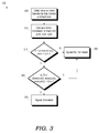
- Figure 3 is a flow diagram of an illustrative method 300 for comparing motion data for the devices 100, 150, in accordance with some embodiments.
- the accelerometer data for each axis for each device 100, 150 is collected.
- a cross-correlation is computed for each axis, rx(d), ry(d), rz(d) as a function of the sample lag, d.
- the maximum value of the cross-correlation function for each axis, max r(d) is compared to a correlation threshold, C TH . If any axis has a maximum correlation coefficient that is less than the correlation threshold, the motion signals are designated as not being correlated in method block 320.
- the sample lag is compared using their coefficient of variation, CV, (std dev/mean) for the sample lag, CV of d[max(rx(d)), max(ry(d)), max(rz(d))]. If the sample lags are less than a predetermined sample lag threshold, D TH , in method block 325, the motion signals are designated as being correlated in method block 330. If the lags are not close in method block 325, the motion signals are designated as not being correlated in method block 320. In some embodiments, the degree of correlation may be used to set the intensity of the alert provided to the user (e.g., the volume).
- certain aspects of the techniques described above may be implemented by one or more processors of a processing system executing software.
- the methods 200, 300 described herein may be implemented by executing software on a computing device, such as the processor 110 of Figure 1 , however, such methods are not abstract in that they improve the operation of the device 100 and the user's experience when operating the device 100.
- the software instructions Prior to execution, the software instructions may be transferred from a non-transitory computer readable storage medium to a memory, such as the memory 115 of Figure 1 .
- the software may include one or more sets of executable instructions stored or otherwise tangibly embodied on a non-transitory computer readable storage medium.
- the software can include the instructions and certain data that, when executed by one or more processors, manipulate the one or more processors to perform one or more aspects of the techniques described above.
- the non-transitory computer readable storage medium can include, for example, a magnetic or optical disk storage device, solid state storage devices such as Flash memory, a cache, random access memory (RAM) or other non-volatile memory device or devices, and the like.
- the executable instructions stored on the non-transitory computer readable storage medium may be in source code, assembly language code, object code, or other instruction format that is interpreted or otherwise executable by one or more processors.
- a computer readable storage medium may include any storage medium, or combination of storage media, accessible by a computer system during use to provide instructions and/or data to the computer system.
- Such storage media can include, but is not limited to, optical media (e.g., compact disc (CD), digital versatile disc (DVD), Blu-Ray disc), magnetic media (e.g., floppy disc , magnetic tape, or magnetic hard drive), volatile memory (e.g., random access memory (RAM) or cache), non-volatile memory (e.g., read-only memory (ROM) or Flash memory), or microelectromechanical systems (MEMS)-based storage media.
- optical media e.g., compact disc (CD), digital versatile disc (DVD), Blu-Ray disc
- magnetic media e.g., floppy disc , magnetic tape, or magnetic hard drive
- volatile memory e.g., random access memory (RAM) or cache
- non-volatile memory e.g., read-only memory (ROM) or Flash memory
- MEMS microelect
- the computer readable storage medium may be embedded in the computing system (e.g., system RAM or ROM), fixedly attached to the computing system (e.g., a magnetic hard drive), removably attached to the computing system (e.g., an optical disc or Universal Serial Bus (USB)-based Flash memory), or coupled to the computer system via a wired or wireless network (e.g., network accessible storage (NAS)).
- system RAM or ROM system RAM or ROM
- USB Universal Serial Bus
- NAS network accessible storage
- a method for detecting physical separation between a first device and a second device includes identifying a moving state of the first device.
- a first set of motion data is collected for the first device responsive to identifying the moving state.
- a second set of motion data is received from a second device.
- the first and second sets of motion data are compared to determine a motion consistency metric.
- An alert signal is generated responsive to the motion consistency metric being less than a predetermined threshold.
- a first device includes a motion sensor to generate motion data and a processor coupled to the orientation sensor.
- the processor is to identify a moving state of the first device, collect a first set of motion data for the first device responsive to identifying the moving state, receive a second set of motion data from a second device communicatively coupled to the first device, compare the first and second sets of motion data to determine a motion consistency metric, and generate an alert signal responsive to the motion consistency metric being less than a predetermined threshold.
- a method includes identifying a moving state of a first device.
- a first set of motion data is collected for the first device responsive to identifying the motion state.
- the first set includes motion data for each of a plurality of axes.
- a motion signal is sent to a second device responsive to identifying the moving state of the first device.
- a second set of motion data is received from the second device.
- the second set includes motion data for each of the plurality of axes.
- the first and second sets of motion data are compared to determine a motion consistency metric for each of the axes.
- An alert signal is generated responsive to the motion consistency metric for any of the axes being less than a predetermined threshold.
Landscapes
- Engineering & Computer Science (AREA)
- Physics & Mathematics (AREA)
- General Physics & Mathematics (AREA)
- Business, Economics & Management (AREA)
- Emergency Management (AREA)
- Computer Networks & Wireless Communication (AREA)
- Signal Processing (AREA)
- Theoretical Computer Science (AREA)
- Health & Medical Sciences (AREA)
- Child & Adolescent Psychology (AREA)
- General Health & Medical Sciences (AREA)
- General Engineering & Computer Science (AREA)
- Computer Hardware Design (AREA)
- Computer Security & Cryptography (AREA)
- Software Systems (AREA)
- Remote Sensing (AREA)
- Radar, Positioning & Navigation (AREA)
- Human Computer Interaction (AREA)
- Emergency Alarm Devices (AREA)
- Alarm Systems (AREA)
- Telephone Function (AREA)
Applications Claiming Priority (1)
| Application Number | Priority Date | Filing Date | Title |
|---|---|---|---|
| US14/693,993 US9582984B2 (en) | 2015-04-23 | 2015-04-23 | Detecting physical separation of portable devices |
Publications (2)
| Publication Number | Publication Date |
|---|---|
| EP3086136A1 true EP3086136A1 (fr) | 2016-10-26 |
| EP3086136B1 EP3086136B1 (fr) | 2020-01-08 |
Family
ID=55755316
Family Applications (1)
| Application Number | Title | Priority Date | Filing Date |
|---|---|---|---|
| EP16162945.6A Active EP3086136B1 (fr) | 2015-04-23 | 2016-03-30 | Détection de la séparation physique de dispositifs portables |
Country Status (4)
| Country | Link |
|---|---|
| US (1) | US9582984B2 (fr) |
| EP (1) | EP3086136B1 (fr) |
| KR (1) | KR101753525B1 (fr) |
| CN (1) | CN106066707A (fr) |
Cited By (1)
| Publication number | Priority date | Publication date | Assignee | Title |
|---|---|---|---|---|
| WO2019089892A1 (fr) | 2017-11-03 | 2019-05-09 | Roku, Inc. | Suivi de proximités de dispositifs et/ou d'objets |
Families Citing this family (6)
| Publication number | Priority date | Publication date | Assignee | Title |
|---|---|---|---|---|
| US9860689B2 (en) | 2015-10-28 | 2018-01-02 | International Business Machines Corporation | Issuing notifications about lost devices |
| KR101876737B1 (ko) * | 2016-11-02 | 2018-08-09 | 현대자동차주식회사 | 지오펜싱 서비스를 제공하는 차량용 전자 장치 및 방법 |
| CN109040438B (zh) * | 2018-07-18 | 2020-12-29 | 东华大学 | 一种基于连续相互验证的移动设备在线防丢检测系统 |
| CN110209281B (zh) * | 2019-06-06 | 2022-03-15 | 瑞典爱立信有限公司 | 对运动信号进行处理的方法、电子设备和介质 |
| CN113286267B (zh) * | 2021-07-23 | 2021-10-26 | 深圳知帮办信息技术开发有限公司 | 高速状态下的互联网通信的流调方法、系统及存储介质 |
| WO2024213244A1 (fr) * | 2023-04-13 | 2024-10-17 | Huawei Technologies Co., Ltd. | Système distribué pour dispositifs intelligents |
Citations (4)
| Publication number | Priority date | Publication date | Assignee | Title |
|---|---|---|---|---|
| US20020169539A1 (en) * | 2001-03-28 | 2002-11-14 | Menard Raymond J. | Method and system for wireless tracking |
| US20120268269A1 (en) * | 2011-04-19 | 2012-10-25 | Qualcomm Incorporated | Threat score generation |
| WO2013191527A1 (fr) * | 2012-06-22 | 2013-12-27 | Balda Solutions Malaysia Sdn Bhd | Système d'alerte sans fil pour la supervision de biens dans une aire personnelle |
| US20140266698A1 (en) * | 2013-03-13 | 2014-09-18 | Qualcomm Incorporated | Systems and methods for monitoring a proximity of a personal item and automatically assigning safe and unsafe zones |
Family Cites Families (9)
| Publication number | Priority date | Publication date | Assignee | Title |
|---|---|---|---|---|
| JP5750742B2 (ja) * | 2010-04-30 | 2015-07-22 | 国立研究開発法人産業技術総合研究所 | 移動体の状態推定装置 |
| US9118776B2 (en) * | 2011-06-03 | 2015-08-25 | Apple Inc. | Location monitoring feature of a mobile device for activating an application subsystem |
| US8818405B2 (en) * | 2011-06-30 | 2014-08-26 | Suman Sheilendra | Recognition system |
| CN202584334U (zh) * | 2012-05-07 | 2012-12-05 | 冷明 | 一种蓝牙移动设备的防盗防丢报警装置 |
| CN202650205U (zh) | 2012-07-24 | 2013-01-02 | 东北石油大学 | 智能防丢器 |
| CN203850854U (zh) | 2013-02-05 | 2014-09-24 | 李明 | 实现移动设备防丢功能的移动电源 |
| WO2014121578A1 (fr) | 2013-02-05 | 2014-08-14 | Li Ming | Dispositif anti-perte permettant de mettre en œuvre une fonction anti-perte d'un dispositif mobile |
| US8773275B1 (en) * | 2013-02-21 | 2014-07-08 | Cynthia Ann Parenteau | Method and system for alerting and retrieving lost device |
| CN104378511B (zh) * | 2014-11-27 | 2018-04-10 | 上海斐讯数据通信技术有限公司 | 移动终端的防盗方法及装置、穿戴设备 |
-
2015
- 2015-04-23 US US14/693,993 patent/US9582984B2/en active Active
-
2016
- 2016-03-30 EP EP16162945.6A patent/EP3086136B1/fr active Active
- 2016-04-20 KR KR1020160048256A patent/KR101753525B1/ko active Active
- 2016-04-21 CN CN201610305033.6A patent/CN106066707A/zh active Pending
Patent Citations (4)
| Publication number | Priority date | Publication date | Assignee | Title |
|---|---|---|---|---|
| US20020169539A1 (en) * | 2001-03-28 | 2002-11-14 | Menard Raymond J. | Method and system for wireless tracking |
| US20120268269A1 (en) * | 2011-04-19 | 2012-10-25 | Qualcomm Incorporated | Threat score generation |
| WO2013191527A1 (fr) * | 2012-06-22 | 2013-12-27 | Balda Solutions Malaysia Sdn Bhd | Système d'alerte sans fil pour la supervision de biens dans une aire personnelle |
| US20140266698A1 (en) * | 2013-03-13 | 2014-09-18 | Qualcomm Incorporated | Systems and methods for monitoring a proximity of a personal item and automatically assigning safe and unsafe zones |
Cited By (4)
| Publication number | Priority date | Publication date | Assignee | Title |
|---|---|---|---|---|
| WO2019089892A1 (fr) | 2017-11-03 | 2019-05-09 | Roku, Inc. | Suivi de proximités de dispositifs et/ou d'objets |
| EP3704877A4 (fr) * | 2017-11-03 | 2021-11-24 | Roku, Inc. | Suivi de proximités de dispositifs et/ou d'objets |
| US11997562B2 (en) | 2017-11-03 | 2024-05-28 | Roku, Inc. | Tracking proximities of devices and/or objects |
| US12225427B2 (en) | 2017-11-03 | 2025-02-11 | Roku, Inc. | Tracking proximities of devices and/or objects |
Also Published As
| Publication number | Publication date |
|---|---|
| US9582984B2 (en) | 2017-02-28 |
| KR101753525B1 (ko) | 2017-07-19 |
| EP3086136B1 (fr) | 2020-01-08 |
| KR20160126889A (ko) | 2016-11-02 |
| US20160314680A1 (en) | 2016-10-27 |
| CN106066707A (zh) | 2016-11-02 |
Similar Documents
| Publication | Publication Date | Title |
|---|---|---|
| US9582984B2 (en) | Detecting physical separation of portable devices | |
| US10015836B2 (en) | Master device for using connection attribute of electronic accessories connections to facilitate locating an accessory | |
| EP3125621B1 (fr) | Établissement de géo-barrières sur la base de positions sémantiques | |
| US20160335876A1 (en) | Wirelessly Tethered Device Tracking | |
| HK1243800A1 (en) | Master device for using connection attribute of electronic accessories connections to facilitate locating an accessory | |
| US20130252628A1 (en) | Crowd Sourcing With Robust Device Position Determination | |
| EP3531722B1 (fr) | Procédé de démarrage d'application et dispositif terminal | |
| CN108235308B (zh) | 数据上报方法、装置、移动终端及计算机可读介质 | |
| US11997562B2 (en) | Tracking proximities of devices and/or objects | |
| WO2015015047A1 (fr) | Estimation de distance | |
| WO2014093027A2 (fr) | Chercheur d'emplacement de dispositif mobile | |
| EP3382426B1 (fr) | Procédé de commutation et dispositif électronique portable | |
| CN112438726A (zh) | 基于可穿戴设备的跌倒报警方法、可穿戴设备及存储介质 | |
| US10614706B2 (en) | Electronic apparatus, control method, and non-transitory computer-readable recording medium | |
| EP3449619A1 (fr) | Système de guidage de proximité en mouvement d'un dispositif mobile | |
| KR20160044779A (ko) | 단말의 협력 센싱 방법 및 협력 센싱을 수행하는 단말 | |
| KR20160019296A (ko) | 휴대폰 분실 방지 시스템 | |
| JP2017108346A (ja) | 情報処理装置、情報処理システム及びプログラム | |
| JP6070561B2 (ja) | 情報処理装置 | |
| JP5712242B2 (ja) | 通知サーバ及びプログラム | |
| CN111343607B (zh) | 一种数据处理方法及相关设备 | |
| JP6823092B2 (ja) | 携帯電子機器、制御方法及び制御プログラム | |
| JP2025155477A (ja) | ワイヤレスネットワークに基づく人体姿勢検出方法、装置、機器及び記憶媒体 | |
| HK40002797A (en) | Master device for using connection attribute of electronic accessories connections to facilitate locating an accessory | |
| US20170308253A1 (en) | Drive mode feature discovery |
Legal Events
| Date | Code | Title | Description |
|---|---|---|---|
| PUAI | Public reference made under article 153(3) epc to a published international application that has entered the european phase |
Free format text: ORIGINAL CODE: 0009012 |
|
| AK | Designated contracting states |
Kind code of ref document: A1 Designated state(s): AL AT BE BG CH CY CZ DE DK EE ES FI FR GB GR HR HU IE IS IT LI LT LU LV MC MK MT NL NO PL PT RO RS SE SI SK SM TR |
|
| AX | Request for extension of the european patent |
Extension state: BA ME |
|
| STAA | Information on the status of an ep patent application or granted ep patent |
Free format text: STATUS: THE APPLICATION HAS BEEN PUBLISHED |
|
| 17P | Request for examination filed |
Effective date: 20170426 |
|
| RBV | Designated contracting states (corrected) |
Designated state(s): AL AT BE BG CH CY CZ DE DK EE ES FI FR GB GR HR HU IE IS IT LI LT LU LV MC MK MT NL NO PL PT RO RS SE SI SK SM TR |
|
| STAA | Information on the status of an ep patent application or granted ep patent |
Free format text: STATUS: REQUEST FOR EXAMINATION WAS MADE |
|
| STAA | Information on the status of an ep patent application or granted ep patent |
Free format text: STATUS: EXAMINATION IS IN PROGRESS |
|
| 17Q | First examination report despatched |
Effective date: 20180530 |
|
| REG | Reference to a national code |
Ref country code: DE Ref legal event code: R079 Ref document number: 602016027653 Country of ref document: DE Free format text: PREVIOUS MAIN CLASS: G01S0005020000 Ipc: H04W0004020000 |
|
| GRAP | Despatch of communication of intention to grant a patent |
Free format text: ORIGINAL CODE: EPIDOSNIGR1 |
|
| STAA | Information on the status of an ep patent application or granted ep patent |
Free format text: STATUS: GRANT OF PATENT IS INTENDED |
|
| RIC1 | Information provided on ipc code assigned before grant |
Ipc: H04W 4/02 20180101AFI20190731BHEP Ipc: G08B 21/24 20060101ALI20190731BHEP Ipc: G08B 21/02 20060101ALI20190731BHEP Ipc: H04W 64/00 20090101ALI20190731BHEP |
|
| INTG | Intention to grant announced |
Effective date: 20190823 |
|
| RIN1 | Information on inventor provided before grant (corrected) |
Inventor name: CREPEAU, MATTHIEU ROBERT Inventor name: LABANA, ROLAND S |
|
| GRAS | Grant fee paid |
Free format text: ORIGINAL CODE: EPIDOSNIGR3 |
|
| GRAA | (expected) grant |
Free format text: ORIGINAL CODE: 0009210 |
|
| STAA | Information on the status of an ep patent application or granted ep patent |
Free format text: STATUS: THE PATENT HAS BEEN GRANTED |
|
| AK | Designated contracting states |
Kind code of ref document: B1 Designated state(s): AL AT BE BG CH CY CZ DE DK EE ES FI FR GB GR HR HU IE IS IT LI LT LU LV MC MK MT NL NO PL PT RO RS SE SI SK SM TR |
|
| REG | Reference to a national code |
Ref country code: GB Ref legal event code: FG4D |
|
| REG | Reference to a national code |
Ref country code: CH Ref legal event code: EP |
|
| REG | Reference to a national code |
Ref country code: DE Ref legal event code: R096 Ref document number: 602016027653 Country of ref document: DE |
|
| REG | Reference to a national code |
Ref country code: IE Ref legal event code: FG4D |
|
| REG | Reference to a national code |
Ref country code: AT Ref legal event code: REF Ref document number: 1224211 Country of ref document: AT Kind code of ref document: T Effective date: 20200215 |
|
| REG | Reference to a national code |
Ref country code: NL Ref legal event code: FP |
|
| PGFP | Annual fee paid to national office [announced via postgrant information from national office to epo] |
Ref country code: GB Payment date: 20200327 Year of fee payment: 5 |
|
| PGFP | Annual fee paid to national office [announced via postgrant information from national office to epo] |
Ref country code: BE Payment date: 20200325 Year of fee payment: 5 |
|
| REG | Reference to a national code |
Ref country code: LT Ref legal event code: MG4D |
|
| PG25 | Lapsed in a contracting state [announced via postgrant information from national office to epo] |
Ref country code: NO Free format text: LAPSE BECAUSE OF FAILURE TO SUBMIT A TRANSLATION OF THE DESCRIPTION OR TO PAY THE FEE WITHIN THE PRESCRIBED TIME-LIMIT Effective date: 20200408 Ref country code: LT Free format text: LAPSE BECAUSE OF FAILURE TO SUBMIT A TRANSLATION OF THE DESCRIPTION OR TO PAY THE FEE WITHIN THE PRESCRIBED TIME-LIMIT Effective date: 20200108 Ref country code: RS Free format text: LAPSE BECAUSE OF FAILURE TO SUBMIT A TRANSLATION OF THE DESCRIPTION OR TO PAY THE FEE WITHIN THE PRESCRIBED TIME-LIMIT Effective date: 20200108 Ref country code: FI Free format text: LAPSE BECAUSE OF FAILURE TO SUBMIT A TRANSLATION OF THE DESCRIPTION OR TO PAY THE FEE WITHIN THE PRESCRIBED TIME-LIMIT Effective date: 20200108 Ref country code: PT Free format text: LAPSE BECAUSE OF FAILURE TO SUBMIT A TRANSLATION OF THE DESCRIPTION OR TO PAY THE FEE WITHIN THE PRESCRIBED TIME-LIMIT Effective date: 20200531 |
|
| PG25 | Lapsed in a contracting state [announced via postgrant information from national office to epo] |
Ref country code: IS Free format text: LAPSE BECAUSE OF FAILURE TO SUBMIT A TRANSLATION OF THE DESCRIPTION OR TO PAY THE FEE WITHIN THE PRESCRIBED TIME-LIMIT Effective date: 20200508 Ref country code: GR Free format text: LAPSE BECAUSE OF FAILURE TO SUBMIT A TRANSLATION OF THE DESCRIPTION OR TO PAY THE FEE WITHIN THE PRESCRIBED TIME-LIMIT Effective date: 20200409 Ref country code: LV Free format text: LAPSE BECAUSE OF FAILURE TO SUBMIT A TRANSLATION OF THE DESCRIPTION OR TO PAY THE FEE WITHIN THE PRESCRIBED TIME-LIMIT Effective date: 20200108 Ref country code: HR Free format text: LAPSE BECAUSE OF FAILURE TO SUBMIT A TRANSLATION OF THE DESCRIPTION OR TO PAY THE FEE WITHIN THE PRESCRIBED TIME-LIMIT Effective date: 20200108 Ref country code: SE Free format text: LAPSE BECAUSE OF FAILURE TO SUBMIT A TRANSLATION OF THE DESCRIPTION OR TO PAY THE FEE WITHIN THE PRESCRIBED TIME-LIMIT Effective date: 20200108 Ref country code: BG Free format text: LAPSE BECAUSE OF FAILURE TO SUBMIT A TRANSLATION OF THE DESCRIPTION OR TO PAY THE FEE WITHIN THE PRESCRIBED TIME-LIMIT Effective date: 20200408 |
|
| REG | Reference to a national code |
Ref country code: DE Ref legal event code: R097 Ref document number: 602016027653 Country of ref document: DE |
|
| PG25 | Lapsed in a contracting state [announced via postgrant information from national office to epo] |
Ref country code: DK Free format text: LAPSE BECAUSE OF FAILURE TO SUBMIT A TRANSLATION OF THE DESCRIPTION OR TO PAY THE FEE WITHIN THE PRESCRIBED TIME-LIMIT Effective date: 20200108 Ref country code: EE Free format text: LAPSE BECAUSE OF FAILURE TO SUBMIT A TRANSLATION OF THE DESCRIPTION OR TO PAY THE FEE WITHIN THE PRESCRIBED TIME-LIMIT Effective date: 20200108 Ref country code: MC Free format text: LAPSE BECAUSE OF FAILURE TO SUBMIT A TRANSLATION OF THE DESCRIPTION OR TO PAY THE FEE WITHIN THE PRESCRIBED TIME-LIMIT Effective date: 20200108 Ref country code: ES Free format text: LAPSE BECAUSE OF FAILURE TO SUBMIT A TRANSLATION OF THE DESCRIPTION OR TO PAY THE FEE WITHIN THE PRESCRIBED TIME-LIMIT Effective date: 20200108 Ref country code: CZ Free format text: LAPSE BECAUSE OF FAILURE TO SUBMIT A TRANSLATION OF THE DESCRIPTION OR TO PAY THE FEE WITHIN THE PRESCRIBED TIME-LIMIT Effective date: 20200108 Ref country code: RO Free format text: LAPSE BECAUSE OF FAILURE TO SUBMIT A TRANSLATION OF THE DESCRIPTION OR TO PAY THE FEE WITHIN THE PRESCRIBED TIME-LIMIT Effective date: 20200108 Ref country code: SK Free format text: LAPSE BECAUSE OF FAILURE TO SUBMIT A TRANSLATION OF THE DESCRIPTION OR TO PAY THE FEE WITHIN THE PRESCRIBED TIME-LIMIT Effective date: 20200108 Ref country code: SM Free format text: LAPSE BECAUSE OF FAILURE TO SUBMIT A TRANSLATION OF THE DESCRIPTION OR TO PAY THE FEE WITHIN THE PRESCRIBED TIME-LIMIT Effective date: 20200108 |
|
| REG | Reference to a national code |
Ref country code: CH Ref legal event code: PL |
|
| PLBE | No opposition filed within time limit |
Free format text: ORIGINAL CODE: 0009261 |
|
| STAA | Information on the status of an ep patent application or granted ep patent |
Free format text: STATUS: NO OPPOSITION FILED WITHIN TIME LIMIT |
|
| REG | Reference to a national code |
Ref country code: AT Ref legal event code: MK05 Ref document number: 1224211 Country of ref document: AT Kind code of ref document: T Effective date: 20200108 |
|
| 26N | No opposition filed |
Effective date: 20201009 |
|
| PG25 | Lapsed in a contracting state [announced via postgrant information from national office to epo] |
Ref country code: LU Free format text: LAPSE BECAUSE OF NON-PAYMENT OF DUE FEES Effective date: 20200330 |
|
| PG25 | Lapsed in a contracting state [announced via postgrant information from national office to epo] |
Ref country code: LI Free format text: LAPSE BECAUSE OF NON-PAYMENT OF DUE FEES Effective date: 20200331 Ref country code: IT Free format text: LAPSE BECAUSE OF FAILURE TO SUBMIT A TRANSLATION OF THE DESCRIPTION OR TO PAY THE FEE WITHIN THE PRESCRIBED TIME-LIMIT Effective date: 20200108 Ref country code: CH Free format text: LAPSE BECAUSE OF NON-PAYMENT OF DUE FEES Effective date: 20200331 Ref country code: IE Free format text: LAPSE BECAUSE OF NON-PAYMENT OF DUE FEES Effective date: 20200330 Ref country code: AT Free format text: LAPSE BECAUSE OF FAILURE TO SUBMIT A TRANSLATION OF THE DESCRIPTION OR TO PAY THE FEE WITHIN THE PRESCRIBED TIME-LIMIT Effective date: 20200108 Ref country code: FR Free format text: LAPSE BECAUSE OF NON-PAYMENT OF DUE FEES Effective date: 20200331 |
|
| PG25 | Lapsed in a contracting state [announced via postgrant information from national office to epo] |
Ref country code: SI Free format text: LAPSE BECAUSE OF FAILURE TO SUBMIT A TRANSLATION OF THE DESCRIPTION OR TO PAY THE FEE WITHIN THE PRESCRIBED TIME-LIMIT Effective date: 20200108 Ref country code: PL Free format text: LAPSE BECAUSE OF FAILURE TO SUBMIT A TRANSLATION OF THE DESCRIPTION OR TO PAY THE FEE WITHIN THE PRESCRIBED TIME-LIMIT Effective date: 20200108 |
|
| PGFP | Annual fee paid to national office [announced via postgrant information from national office to epo] |
Ref country code: NL Payment date: 20210325 Year of fee payment: 6 |
|
| GBPC | Gb: european patent ceased through non-payment of renewal fee |
Effective date: 20210330 |
|
| REG | Reference to a national code |
Ref country code: BE Ref legal event code: MM Effective date: 20210331 |
|
| PG25 | Lapsed in a contracting state [announced via postgrant information from national office to epo] |
Ref country code: GB Free format text: LAPSE BECAUSE OF NON-PAYMENT OF DUE FEES Effective date: 20210330 |
|
| PG25 | Lapsed in a contracting state [announced via postgrant information from national office to epo] |
Ref country code: TR Free format text: LAPSE BECAUSE OF FAILURE TO SUBMIT A TRANSLATION OF THE DESCRIPTION OR TO PAY THE FEE WITHIN THE PRESCRIBED TIME-LIMIT Effective date: 20200108 Ref country code: MT Free format text: LAPSE BECAUSE OF FAILURE TO SUBMIT A TRANSLATION OF THE DESCRIPTION OR TO PAY THE FEE WITHIN THE PRESCRIBED TIME-LIMIT Effective date: 20200108 Ref country code: CY Free format text: LAPSE BECAUSE OF FAILURE TO SUBMIT A TRANSLATION OF THE DESCRIPTION OR TO PAY THE FEE WITHIN THE PRESCRIBED TIME-LIMIT Effective date: 20200108 |
|
| PG25 | Lapsed in a contracting state [announced via postgrant information from national office to epo] |
Ref country code: MK Free format text: LAPSE BECAUSE OF FAILURE TO SUBMIT A TRANSLATION OF THE DESCRIPTION OR TO PAY THE FEE WITHIN THE PRESCRIBED TIME-LIMIT Effective date: 20200108 Ref country code: AL Free format text: LAPSE BECAUSE OF FAILURE TO SUBMIT A TRANSLATION OF THE DESCRIPTION OR TO PAY THE FEE WITHIN THE PRESCRIBED TIME-LIMIT Effective date: 20200108 |
|
| PG25 | Lapsed in a contracting state [announced via postgrant information from national office to epo] |
Ref country code: BE Free format text: LAPSE BECAUSE OF NON-PAYMENT OF DUE FEES Effective date: 20210331 |
|
| REG | Reference to a national code |
Ref country code: NL Ref legal event code: MM Effective date: 20220401 |
|
| PG25 | Lapsed in a contracting state [announced via postgrant information from national office to epo] |
Ref country code: NL Free format text: LAPSE BECAUSE OF NON-PAYMENT OF DUE FEES Effective date: 20220401 |
|
| P01 | Opt-out of the competence of the unified patent court (upc) registered |
Effective date: 20230627 |
|
| PGFP | Annual fee paid to national office [announced via postgrant information from national office to epo] |
Ref country code: DE Payment date: 20260320 Year of fee payment: 11 |