EP3086331A1 - Non-contact marked potentiometer - Google Patents
Non-contact marked potentiometer Download PDFInfo
- Publication number
- EP3086331A1 EP3086331A1 EP14871839.8A EP14871839A EP3086331A1 EP 3086331 A1 EP3086331 A1 EP 3086331A1 EP 14871839 A EP14871839 A EP 14871839A EP 3086331 A1 EP3086331 A1 EP 3086331A1
- Authority
- EP
- European Patent Office
- Prior art keywords
- rotating shaft
- linear potentiometer
- slider
- permanent magnet
- noncontact
- Prior art date
- Legal status (The legal status is an assumption and is not a legal conclusion. Google has not performed a legal analysis and makes no representation as to the accuracy of the status listed.)
- Granted
Links
Images

Classifications
-
- H—ELECTRICITY
- H01—ELECTRIC ELEMENTS
- H01C—RESISTORS
- H01C10/00—Adjustable resistors
- H01C10/14—Adjustable resistors adjustable by auxiliary driving means
-
- H—ELECTRICITY
- H01—ELECTRIC ELEMENTS
- H01C—RESISTORS
- H01C10/00—Adjustable resistors
- H01C10/30—Adjustable resistors the contact sliding along resistive element
Definitions
- the present invention relates to a linear potentiometer, in particular to a noncontact linear potentiometer which converts a linear displacement into a rotational angular displacement and performs detection through a tunneling magnetoresistive sensor.
- This potentiometer is a new type of electronic component, having high linearity, high reliability, and the like, and it can be applied to fields such as aviation, spaceflight, precision instruments and meters, and the like.
- a potentiometer with long-service-life, high-performance and high-reliability is urgently needed.
- rotary potentiometers There is, however, little research on linear sliding potentiometers.
- a linear sliding type potentiometer uses an electronic brush structure to achieve the function of the product by changing the position of the electronic brush by means of linear sliding.
- Chinese patent application 201010528601.1 titled "Linear sliding type potentiometer” discloses a linear sliding type potentiometer, which comprises a housing, a sliding shaft capable of moving in the housing and an output bus installed on the housing, wherein a resistor assembly is installed in the housing, and the resistor assembly comprises an insulating board provided with a conductive tracks and three installation wires installed on the insulating board.
- the sliding shaft projects into an interior of the housing, and an electronic brush assembly is installed at the end of the sliding shaft which projects into the housing, the electronic brush assembly comprises a slider fixed on the sliding shaft, a spring leaf connected with the electronic brush is fixed on the slider, and the electronic brush is in contact with the conductive track on the insulating board.
- the sensor can convert linear displacement to an electric signal, the structure thereof is complex, the service life is short and thus the sensor is not suitable for frequent slider motion.
- the applicant makes some improvements to the structure and proposes a new patent application 201220557883.2 , this patent application discloses a coaxial duplex linear sliding type potentiometer.
- the potentiometer comprises a housing, a conductive plastic substrate I and a conductive plastic substrate II, wherein a lower surface of the conductive plastic substrate I and an upper surface of the conductive plastic substrate II are respectively provided with a resistor, a sliding rod projecting out of the housing between the conductive plastic substrate I and the conductive plastic substrate II, a slider is provided at the end of the sliding rod which projects into the housing, and upper and lower side surfaces of the slider that respectively are provided with two electronic brushes.
- Voltage signals output by the potentiometer have a linear relationship with linear displacements of an adjusting shaft, and conversion from mechanical movement to electric signals can be realized. Although the reliability thereof is improved relative to the former one, the structure thereof is more complex, the cost is also higher and the service life is not long enough.
- the purpose of the present invention is to overcome the above-mentioned defects in the prior art and provide a noncontact linear potentiometer with ultra-long service life.
- the potentiometer is compact in structure and simple in fabrication, and can convert linear movement into rotation and realize detection of a rotating angle using a noncontact tunneling magnetoresistive sensor, in order to obtain the improvement of the service life.
- the present invention provides a noncontact linear potentiometer.
- the noncontact linear potentiometer comprises a slider, a rotating shaft, a tunneling magnetoresistive sensor, a permanent magnet and support structures; the slider is provided with a first through hole; the rotating shaft penetrates through the first through hole and the two ends of the rotating shaft are rotatably installed on the support structures; the slider slides along an axial direction of the rotating shaft, and the sliding of the slider drives the rotating shaft to rotate; the permanent magnet is located at one end of the rotating shaft and rotates with the rotating shaft; and the tunneling magnetoresistive sensor is located adjacent to the permanent magnet and is used for detecting a magnetic field produced by the rotating permanent magnet and converting the detected magnetic field into a voltage signal for output.
- the noncontact linear potentiometer further comprises a guide rod
- the slider is further provided with a second through hole; and the guide rod penetrates through the second through hole and is in parallel with the rotating shaft, and two ends of the guide rod are fixed on the support structures.
- the tunneling magnetoresistive sensor is a biaxial rotary magnetic sensor or two orthogonal uniaxial rotary magnetic sensors.
- the permanent magnet is disc-shaped, annular or square.
- the tunneling magnetoresistive sensor is a biaxial linear magnetic sensor.
- the permanent magnet is disc-shaped or annular.
- a central axis of the tunneling magnetoresistive sensor and central axes of the permanent magnet and the rotating shaft are the same.
- an internal magnetizing direction of the permanent magnet is perpendicular to the axial direction of the rotating shaft.
- the noncontact linear potentiometer further comprises a ball bearing which is located between the slider and the rotating shaft.
- a pin used for withstanding the ball bearing is assembled between the slider and the rotating shaft, and the pin can slide along a direction in parallel with a plane formed by the rotating shaft and the guide rod and perpendicular to the axial direction of the rotating shaft.
- a spring leaf is assembled between the slider and the pin.
- the rotating shaft thereon comprises a spiral groove along which the ball bearing rolls.
- a spiral thread on a lead screw is rolled by using a thread rolling plate and a desired surface hardness on the lead screw is obtained by adopting an electroplating process or a heat treatment process.
- a bottom of the noncontact linear potentiometer is provided with a printed circuit board which further comprises wiring pins thereon, and the tunneling magnetoresistive sensor is soldered on the printed circuit board.
- the rotating shaft is a lead screw or a torsion rod.
- the principle of the screw rod is reversely applied, and the slider is used as a power source to drive the rotating shaft to rotate, so as to convert linear movement into circular movement.
- the ball bearing, the pin and the spring leaf are assembled between the slider and the rotating shaft.
- a guide rod is used for providing sliding guide of the slider.
- the role of the ball bearing is to convert sliding friction into rolling friction, such that the friction force is minimized.
- the spring leaf and the slidable pin are used for eliminating a gap caused by fabrication error and assembling, so as to guarantee the accuracy of forward and backward travels.
- the present invention has the following beneficial effects:
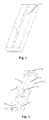
- Fig. 1 is a schematic diagram of an external structure of a noncontact linear potentiometer in the present invention.
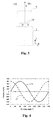
- Fig. 2 is a schematic diagram of an internal structure of the potentiometer after removing a housing 13.
- the potentiometer comprises a rotatable rotating shaft 1, a slider 2, a fixed guide rod 3, support structures 4 and 5, a tunneling magnetoresistive (TMR) sensor 9, a permanent magnet 10 and a printed circuit board 12.
- TMR tunneling magnetoresistive
- the rotating shaft 1 thereon is provided with a spiral protrusion or groove which can convert sliding of the slider into rotation of the rotating shaft.
- the rotating shaft 1 is a lead screw.
- the lead screw 1 penetrates through a corresponding first through hole in the slider 2, two ends of the lead screw 1 are rotatably installed onto the support structures 4 and 5, one end of the guide rod 3 is fixed on the support structure 4, and the other end penetrates through a corresponding second through hole in the slider 2 and is fixed onto the support structure 5.
- the guide rod 3 is in parallel with the lead screw 1.
- the tunneling magnetoresistive sensor 9 is located adjacent to the permanent magnet 10 and is soldered on the Printed Circuit Board (PCB) 12, as shown in Fig. 2 , and the printed circuit board 12 is located at a bottom of the potentiometer and further comprises wiring pins (not shown) thereon.
- the tunneling magnetoresistive sensor 9 can be a biaxial rotary magnetic sensor or two orthogonal uniaxial rotary magnetic sensors, in this case, the permanent magnet 10 can be disc-shaped, annular or square, and a central axis of the tunneling magnetoresistive sensor 9 and central axes of the permanent magnet 10 and the lead screw 1 are the same.
- the tunneling magnetoresistive sensor 9 can also be a biaxial linear magnetic sensor, in this case, the permanent magnet 10 can be disc-shaped or annular, and the tunneling magnetoresistive sensor 9 is located around the permanent magnet 10, and preferably is placed coaxial with the permanent magnet 10.
- An internal magnetizing direction of the permanent magnet 10 is as shown by an N pole and an S pole in Fig. 3 , from which it can be seen that the magnetizing direction is perpendicular to the Z-axis direction 100.
- the above-mentioned guide rod 3 is a preferred mode and is used for providing sliding guide of the slider 2.
- the tunneling magnetoresistive sensor 9 converts the amplitude of the magnetic field produced by the permanent magnet 10 into an analog voltage signal, and the obtained analog voltage signal can be directly output and can also be output after being converted into a digital signal by using an analog-to-digital converter (ADC) circuit.
- ADC analog-to-digital converter
- the rotating angle of the permanent magnet 10, i.e., the rotating angle of the lead screw 1 can be known according to the output signal.
- a ball bearing 6, a pin 7 and a spring leaf 8 are assembled between the slider 2 and the lead screw 1, as shown in Fig. 5 .
- the ball bearing 6 rolls along the spiral groove on the lead screw 1 and the role thereof is to convert sliding friction into rolling friction to minimize the friction force, so as to prolong the service life.
- the pin 7 is used for withstanding the ball bearing 6 and can slide along a direction in parallel with a plane formed by the rotating shaft and the guide rod and perpendicular to the axial direction of the rotating shaft, i.e., along an X-axis direction, and the spring leaf 8 and the pin 7 are used for eliminating a gap caused by fabrication error and assembling, so as to guarantee the accuracy of forward and backward travels.
- the above-mentioned X-axis direction is a direction in parallel with the plane formed by the rotating shaft and the guide rod and perpendicular to the axial direction of the rotating shaft.
- the lead screw 1 is improved by adopting a thread rolling process, a spiral thread needed for travel guide is rolled by using a thread rolling plate, and the slider 2 can slide along the spiral thread.
- a desired surface hardness can be obtained by adopting a common electroplating process or heat treatment process, so as to reduce the wear and prolong the service life.
- the lead screw 1 can also be replaced with a torsion rod, a structure of which is as shown in Fig. 6 .
- a material for fabricating the torsion rod is relatively cheap, the fabrication process is also simpler and thus the cost is reduced.
- Other parts are all fabricated by adopting common fabrication processes and are easy to implement.
Landscapes
- Engineering & Computer Science (AREA)
- Microelectronics & Electronic Packaging (AREA)
- Transmission And Conversion Of Sensor Element Output (AREA)
- Hall/Mr Elements (AREA)
- Adjustable Resistors (AREA)
Abstract
Description
- The present invention relates to a linear potentiometer, in particular to a noncontact linear potentiometer which converts a linear displacement into a rotational angular displacement and performs detection through a tunneling magnetoresistive sensor.
- This potentiometer is a new type of electronic component, having high linearity, high reliability, and the like, and it can be applied to fields such as aviation, spaceflight, precision instruments and meters, and the like. With the development of technology, a potentiometer with long-service-life, high-performance and high-reliability is urgently needed. At present, there has been great progress on rotary potentiometers. There is, however, little research on linear sliding potentiometers.
- In the prior art, a linear sliding type potentiometer uses an electronic brush structure to achieve the function of the product by changing the position of the electronic brush by means of linear sliding.
Chinese patent application 201010528601.1 201220557883.2 - The purpose of the present invention is to overcome the above-mentioned defects in the prior art and provide a noncontact linear potentiometer with ultra-long service life. The potentiometer is compact in structure and simple in fabrication, and can convert linear movement into rotation and realize detection of a rotating angle using a noncontact tunneling magnetoresistive sensor, in order to obtain the improvement of the service life.
- In order to realize the above-mentioned purpose, the present invention is implemented by adopting the following technical solution:
- The present invention provides a noncontact linear potentiometer. The noncontact linear potentiometer comprises a slider, a rotating shaft, a tunneling magnetoresistive sensor, a permanent magnet and support structures; the slider is provided with a first through hole;
the rotating shaft penetrates through the first through hole and the two ends of the rotating shaft are rotatably installed on the support structures;
the slider slides along an axial direction of the rotating shaft, and the sliding of the slider drives the rotating shaft to rotate;
the permanent magnet is located at one end of the rotating shaft and rotates with the rotating shaft; and
the tunneling magnetoresistive sensor is located adjacent to the permanent magnet and is used for detecting a magnetic field produced by the rotating permanent magnet and converting the detected magnetic field into a voltage signal for output. - Preferably, the noncontact linear potentiometer further comprises a guide rod, and the slider is further provided with a second through hole; and the guide rod penetrates through the second through hole and is in parallel with the rotating shaft, and two ends of the guide rod are fixed on the support structures.
- Preferably, the tunneling magnetoresistive sensor is a biaxial rotary magnetic sensor or two orthogonal uniaxial rotary magnetic sensors.
- Preferably, the permanent magnet is disc-shaped, annular or square.
- Preferably, the tunneling magnetoresistive sensor is a biaxial linear magnetic sensor.
- Preferably, the permanent magnet is disc-shaped or annular.
- Preferably, a central axis of the tunneling magnetoresistive sensor and central axes of the permanent magnet and the rotating shaft are the same.
- Preferably, an internal magnetizing direction of the permanent magnet is perpendicular to the axial direction of the rotating shaft.
- Preferably, the noncontact linear potentiometer further comprises a ball bearing which is located between the slider and the rotating shaft.
- Preferably, a pin used for withstanding the ball bearing is assembled between the slider and the rotating shaft, and the pin can slide along a direction in parallel with a plane formed by the rotating shaft and the guide rod and perpendicular to the axial direction of the rotating shaft.
- Preferably, a spring leaf is assembled between the slider and the pin.
- Preferably, the rotating shaft thereon comprises a spiral groove along which the ball bearing rolls.
- Preferably, a spiral thread on a lead screw is rolled by using a thread rolling plate and a desired surface hardness on the lead screw is obtained by adopting an electroplating process or a heat treatment process.
- Preferably, a bottom of the noncontact linear potentiometer is provided with a printed circuit board which further comprises wiring pins thereon, and the tunneling magnetoresistive sensor is soldered on the printed circuit board.
- Preferably, the rotating shaft is a lead screw or a torsion rod.
- The principle of the screw rod is reversely applied, and the slider is used as a power source to drive the rotating shaft to rotate, so as to convert linear movement into circular movement. The ball bearing, the pin and the spring leaf are assembled between the slider and the rotating shaft. In addition, a guide rod is used for providing sliding guide of the slider. The role of the ball bearing is to convert sliding friction into rolling friction, such that the friction force is minimized. The spring leaf and the slidable pin are used for eliminating a gap caused by fabrication error and assembling, so as to guarantee the accuracy of forward and backward travels.
- Compared with the prior art, the present invention has the following beneficial effects:
- 1) the structure of the present invention is simple, the fabrication is easy and the cost is low;
- 2) since the linear sliding displacement is converted into the rotational angular displacement and the rotating angle of the rotating shaft is sensed through the tunneling magnetoresistive sensor in the present invention, the linearity thereof is improved and the power consumption is also reduced;
- 3) the tunneling magnetoresistive sensor in the present invention can realize the measurement without being in contact with the rotating shaft, and thus the service life is improved; and
- 4) since the slider only needs to be manually operated to slide along the rotating shaft and the guide rod in the present invention, the operation is simple and easy to realize.
- In order to more clearly illustrate the technical solution in the embodiments of the present invention, the drawings which need to be used in the description of the embodiments will be simply introduced below. Obviously, the drawings described below are just some embodiments of the present invention. For one skilled in the art, other drawings can be obtained according to these drawings without contributing any inventive labor.
-
Fig. 1 is a schematic diagram of an external structure of a noncontact linear potentiometer in the present invention. -
Fig. 2 is a schematic diagram of an internal structure of a noncontact linear potentiometer in the present invention. -
Fig. 3 is a sectional schematic diagram of a position relationship between a tunneling magnetoresistive sensor and a permanent magnet. -
Fig. 4 is a curve chart of a relationship between output voltage of a noncontact linear potentiometer and a rotating angle of a permanent magnet in the present invention. -
Fig. 5 is a local sectional view of a noncontact linear potentiometer in the present invention. -
Fig. 6 is a structural schematic diagram of a torsion rod replacing a lead screw. - The present invention will be illustrated below in detail by referring to the drawings in combination with the embodiments.
-
Fig. 1 is a schematic diagram of an external structure of a noncontact linear potentiometer in the present invention.Fig. 2 is a schematic diagram of an internal structure of the potentiometer after removing ahousing 13. The potentiometer comprises a rotatablerotating shaft 1, a slider 2, afixed guide rod 3,support structures sensor 9, apermanent magnet 10 and aprinted circuit board 12. In the specific embodiments of the present invention, therotating shaft 1 thereon is provided with a spiral protrusion or groove which can convert sliding of the slider into rotation of the rotating shaft. In this embodiment, therotating shaft 1 is a lead screw. Thelead screw 1 penetrates through a corresponding first through hole in the slider 2, two ends of thelead screw 1 are rotatably installed onto thesupport structures guide rod 3 is fixed on thesupport structure 4, and the other end penetrates through a corresponding second through hole in the slider 2 and is fixed onto thesupport structure 5. In this embodiment, theguide rod 3 is in parallel with thelead screw 1. By moving ahandle 11 on the slider 2, the slider 2 can be caused to slide along an axial direction of thelead screw 1 and the guide rod 3 (i.e., a Z-axis direction 100 inFig. 3 ), so as to drive thelead screw 1 to rotate. Thepermanent magnet 10 is located at one end of thelead screw 1 and also rotates with thelead screw 1. Thetunneling magnetoresistive sensor 9 is located adjacent to thepermanent magnet 10 and is soldered on the Printed Circuit Board (PCB) 12, as shown inFig. 2 , and the printedcircuit board 12 is located at a bottom of the potentiometer and further comprises wiring pins (not shown) thereon. Thetunneling magnetoresistive sensor 9 can be a biaxial rotary magnetic sensor or two orthogonal uniaxial rotary magnetic sensors, in this case, thepermanent magnet 10 can be disc-shaped, annular or square, and a central axis of thetunneling magnetoresistive sensor 9 and central axes of thepermanent magnet 10 and thelead screw 1 are the same. Thetunneling magnetoresistive sensor 9 can also be a biaxial linear magnetic sensor, in this case, thepermanent magnet 10 can be disc-shaped or annular, and thetunneling magnetoresistive sensor 9 is located around thepermanent magnet 10, and preferably is placed coaxial with thepermanent magnet 10. An internal magnetizing direction of thepermanent magnet 10 is as shown by an N pole and an S pole inFig. 3 , from which it can be seen that the magnetizing direction is perpendicular to the Z-axis direction 100. - It needs to be stated that the above-mentioned
guide rod 3 is a preferred mode and is used for providing sliding guide of the slider 2. - When the
permanent magnet 10 rotates with thelead screw 1 along arotating direction 101, curves of changes in magnetic field components in X-axis and Y-axis which are detected by thetunneling magnetoresistive sensor 9 with rotating angles are as shown bycurves 41 and 42 inFig. 4 . Thetunneling magnetoresistive sensor 9 converts the amplitude of the magnetic field produced by thepermanent magnet 10 into an analog voltage signal, and the obtained analog voltage signal can be directly output and can also be output after being converted into a digital signal by using an analog-to-digital converter (ADC) circuit. The rotating angle of thepermanent magnet 10, i.e., the rotating angle of thelead screw 1 can be known according to the output signal. - A ball bearing 6, a
pin 7 and a spring leaf 8 are assembled between the slider 2 and thelead screw 1, as shown inFig. 5 . The ball bearing 6 rolls along the spiral groove on thelead screw 1 and the role thereof is to convert sliding friction into rolling friction to minimize the friction force, so as to prolong the service life. Thepin 7 is used for withstanding the ball bearing 6 and can slide along a direction in parallel with a plane formed by the rotating shaft and the guide rod and perpendicular to the axial direction of the rotating shaft, i.e., along an X-axis direction, and the spring leaf 8 and thepin 7 are used for eliminating a gap caused by fabrication error and assembling, so as to guarantee the accuracy of forward and backward travels. The above-mentioned X-axis direction is a direction in parallel with the plane formed by the rotating shaft and the guide rod and perpendicular to the axial direction of the rotating shaft. - The
lead screw 1 is improved by adopting a thread rolling process, a spiral thread needed for travel guide is rolled by using a thread rolling plate, and the slider 2 can slide along the spiral thread. In order to improve the service life, a desired surface hardness can be obtained by adopting a common electroplating process or heat treatment process, so as to reduce the wear and prolong the service life. Moreover, thelead screw 1 can also be replaced with a torsion rod, a structure of which is as shown inFig. 6 . A material for fabricating the torsion rod is relatively cheap, the fabrication process is also simpler and thus the cost is reduced. Other parts are all fabricated by adopting common fabrication processes and are easy to implement. - The above-mentioned embodiments are just preferred embodiments of the present invention and are not used for limiting the present invention. For one skilled in the art, various alterations and variations may be made to the present invention. Any modification, equivalent replacement, improvement and the like made within the spirit and principle of the present invention shall also be included in the protection range of the present invention.
Claims (15)
- A noncontact linear potentiometer, characterized in that the noncontact linear potentiometer comprises a slider, a rotating shaft, a tunneling magnetoresistive sensor, a permanent magnet and support structures; wherein the slider is provided with a first through hole; the rotating shaft penetrates through the first through hole and the two ends of the rotating shaft are rotatably installed on the support structures;
the slider slides along an axial direction of the rotating shaft, and the sliding of the slider drives the rotating shaft to rotate;
the permanent magnet is located at one end of the rotating shaft and rotates with the rotating shaft; and
the tunneling magnetoresistive sensor is located adjacent to the permanent magnet and is used for detecting a magnetic field produced by the rotating permanent magnet and converting the detected magnetic field into a voltage signal for output. - The noncontact linear potentiometer according to claim 1, characterized in that the noncontact linear potentiometer further comprises a guide rod, and the slider is further provided with a second through hole; wherein the guide rod penetrates through the second through hole and is in parallel with the rotating shaft, and two ends of the guide rod are fixed on the support structures.
- The noncontact linear potentiometer according to claim 1, characterized in that the tunneling magnetoresistive sensor is a biaxial rotary magnetic sensor or two orthogonal uniaxial rotary magnetic sensors.
- The noncontact linear potentiometer according to claim 3, characterized in that the permanent magnet is disc-shaped, annular or square.
- The noncontact linear potentiometer according to claim 1, characterized in that the tunneling magnetoresistive sensor is a biaxial linear magnetic sensor.
- The noncontact linear potentiometer according to claim 5, characterized in that the permanent magnet is disc-shaped or annular.
- The noncontact linear potentiometer according to claim 1, characterized in that a central axis of the tunneling magnetoresistive sensor and central axes of the permanent magnet and the rotating shaft are the same.
- The noncontact linear potentiometer according to claim 1, characterized in that an internal magnetizing direction of the permanent magnet is perpendicular to the axial direction of the rotating shaft.
- The noncontact linear potentiometer according to claim 2, characterized in that the noncontact linear potentiometer further comprises a ball bearing which is located between the slider and the rotating shaft.
- The noncontact linear potentiometer according to claim 9, characterized in that a pin used for withstanding the ball bearing is assembled between the slider and the rotating shaft, and the pin can slide along a direction in parallel with a plane formed by the rotating shaft and the guide rod and perpendicular to the axial direction of the rotating shaft.
- The noncontact linear potentiometer according to claim 10, characterized in that a spring leaf is assembled between the slider and the pin.
- The noncontact linear potentiometer according to claim 9, characterized in that the rotating shaft thereon comprises a spiral groove along which the ball bearing rolls.
- The noncontact linear potentiometer according to claim 1, characterized in that a bottom of the noncontact linear potentiometer is provided with a printed circuit board which further comprises wiring pins thereon, and the tunneling magnetoresistive sensor is soldered on the printed circuit board.
- The noncontact linear potentiometer according to claim 1, characterized in that the rotating shaft is a lead screw or a torsion rod.
- The noncontact linear potentiometer according to claim 14, characterized in that a spiral thread on the lead screw is rolled by using a thread rolling plate and a desired surface hardness on the lead screw is obtained by adopting an electroplating process or a heat treatment process.
Applications Claiming Priority (2)
| Application Number | Priority Date | Filing Date | Title |
|---|---|---|---|
| CN201310698204.2A CN103646736B (en) | 2013-12-18 | 2013-12-18 | Noncontact-type scribing potentiometer |
| PCT/CN2014/094064 WO2015090198A1 (en) | 2013-12-18 | 2014-12-17 | Non-contact marked potentiometer |
Publications (3)
| Publication Number | Publication Date |
|---|---|
| EP3086331A1 true EP3086331A1 (en) | 2016-10-26 |
| EP3086331A4 EP3086331A4 (en) | 2017-05-10 |
| EP3086331B1 EP3086331B1 (en) | 2018-04-11 |
Family
ID=50251937
Family Applications (1)
| Application Number | Title | Priority Date | Filing Date |
|---|---|---|---|
| EP14871839.8A Active EP3086331B1 (en) | 2013-12-18 | 2014-12-17 | Non contact linear potentiometer |
Country Status (5)
| Country | Link |
|---|---|
| US (1) | US9978485B2 (en) |
| EP (1) | EP3086331B1 (en) |
| JP (1) | JP6389894B2 (en) |
| CN (1) | CN103646736B (en) |
| WO (1) | WO2015090198A1 (en) |
Families Citing this family (8)
| Publication number | Priority date | Publication date | Assignee | Title |
|---|---|---|---|---|
| CN103646736B (en) * | 2013-12-18 | 2017-01-18 | 江苏多维科技有限公司 | Noncontact-type scribing potentiometer |
| CN108645455B (en) * | 2018-08-15 | 2023-09-15 | 无锡市航鹄科技有限公司 | Potentiometer assembly test system and test method thereof |
| CN110500941B (en) * | 2019-08-27 | 2024-05-14 | 成都宏明电子股份有限公司 | Linear displacement magneto-dependent sensor with RS485 linear output |
| CN114650751B (en) * | 2019-10-28 | 2024-04-12 | 爱格升公司 | System and method for lift estimation |
| CN111941380B (en) * | 2020-09-22 | 2023-01-03 | 诸暨市中坚机械有限公司 | Thread groove opening is seted up and is drawn mechanism with supplementary thread line |
| CN113327733B (en) * | 2021-06-15 | 2025-07-01 | 上海思博机械电气有限公司 | A multi-turn non-contact potentiometer based on the screw principle |
| CN114755462B (en) * | 2022-03-09 | 2024-07-16 | 中核核电运行管理有限公司 | Frameless long single-rod double-arrangement synchronous potentiometer |
| JP7489739B1 (en) | 2023-06-02 | 2024-05-24 | 栄通信工業株式会社 | Linear Slide Potentiometer |
Family Cites Families (25)
| Publication number | Priority date | Publication date | Assignee | Title |
|---|---|---|---|---|
| DE1665658A1 (en) * | 1966-06-23 | 1971-04-08 | Siemens Ag | Arrangement for setting the lighting of stages, studios and the like. |
| US4088977A (en) * | 1977-02-02 | 1978-05-09 | Illinois Tool Works Inc. | Contactless linear position sensor |
| DE3447312A1 (en) * | 1984-12-24 | 1986-07-10 | Standard Elektrik Lorenz Ag | MAGNETIC SENSOR |
| JPS6217416A (en) * | 1985-07-15 | 1987-01-26 | 株式会社 興和工業所 | Manufacture of thread product |
| JPH03179216A (en) * | 1989-12-08 | 1991-08-05 | Alps Electric Co Ltd | Magnetic rotation sensor and manufacture thereof |
| DE9010389U1 (en) * | 1990-07-10 | 1991-11-07 | Merklein, Gernot, 8740 Bad Neustadt | Rotary potentiometer |
| DE4109658A1 (en) * | 1991-03-23 | 1992-09-24 | Bosch Gmbh Robert | Acceleration pedal position detection in motor vehicle - uses non-contact device with permanent magnet movement relative to magnetoresistive plate |
| DE19536433C2 (en) * | 1995-09-29 | 1999-04-08 | Siemens Ag | Device for contactless position detection of an object and use of the device |
| JP3313967B2 (en) * | 1996-02-20 | 2002-08-12 | アルプス電気株式会社 | Detector |
| DE19612422C2 (en) * | 1996-03-28 | 2000-06-15 | Siemens Ag | Potentiometer device with a linearly displaceable control element and signal-generating means |
| US6133730A (en) * | 1998-04-22 | 2000-10-17 | Winn; William E. | Apparatus for positioning a detection device for monitoring a rotatable machine element |
| JP4352189B2 (en) * | 1998-08-20 | 2009-10-28 | 株式会社安川電機 | Magnetic encoder and motor with magnetic encoder |
| JP2000158077A (en) * | 1998-11-20 | 2000-06-13 | Nec Ibaraki Ltd | Screw forging method, and thread rolling tool therefor |
| JP2002090107A (en) * | 2000-09-11 | 2002-03-27 | Alps Electric Co Ltd | Position sensor |
| JP2003008101A (en) * | 2001-06-20 | 2003-01-10 | Ricoh Co Ltd | Tunnel magnetoresistive element and azimuth detecting system using the element |
| DE10134259A1 (en) * | 2001-07-18 | 2003-02-06 | Zf Lemfoerder Metallwaren Ag | Ball joint with integrated angle sensor |
| US6617958B1 (en) * | 2002-04-24 | 2003-09-09 | Taiwan Alpha Electronic Co., Ltd. | Optical potentiometer |
| JP4635745B2 (en) * | 2004-07-06 | 2011-02-23 | ヤマハ株式会社 | Slide operation device |
| CN102456457A (en) | 2010-11-01 | 2012-05-16 | 陕西宏星电器有限责任公司 | Direct sliding potentiometer |
| JP3170249U (en) * | 2011-06-28 | 2011-09-08 | 株式会社飯塚製作所 | Screw repair device |
| CN202487305U (en) * | 2012-03-28 | 2012-10-10 | 上海思博机械电气有限公司 | Non-contact type digital potentiometer |
| CN202905355U (en) | 2012-10-26 | 2013-04-24 | 陕西宏星电器有限责任公司 | Coaxial duplex straight-sliding type potentiometer |
| CN203260444U (en) * | 2013-04-01 | 2013-10-30 | 江苏多维科技有限公司 | Non-contact potentiometer |
| CN203659562U (en) * | 2013-12-18 | 2014-06-18 | 江苏多维科技有限公司 | Non-contact type line-marking potentiometer |
| CN103646736B (en) * | 2013-12-18 | 2017-01-18 | 江苏多维科技有限公司 | Noncontact-type scribing potentiometer |
-
2013
- 2013-12-18 CN CN201310698204.2A patent/CN103646736B/en active Active
-
2014
- 2014-12-17 JP JP2016541000A patent/JP6389894B2/en active Active
- 2014-12-17 EP EP14871839.8A patent/EP3086331B1/en active Active
- 2014-12-17 WO PCT/CN2014/094064 patent/WO2015090198A1/en not_active Ceased
- 2014-12-17 US US15/106,127 patent/US9978485B2/en active Active
Also Published As
| Publication number | Publication date |
|---|---|
| EP3086331A4 (en) | 2017-05-10 |
| CN103646736A (en) | 2014-03-19 |
| JP2017503345A (en) | 2017-01-26 |
| EP3086331B1 (en) | 2018-04-11 |
| WO2015090198A1 (en) | 2015-06-25 |
| US20180053585A1 (en) | 2018-02-22 |
| US9978485B2 (en) | 2018-05-22 |
| CN103646736B (en) | 2017-01-18 |
| JP6389894B2 (en) | 2018-09-12 |
Similar Documents
| Publication | Publication Date | Title |
|---|---|---|
| US9978485B2 (en) | Non-contact linear potentiometer | |
| US7116100B1 (en) | Position sensing for moveable mechanical systems and associated methods and apparatus | |
| KR101476564B1 (en) | Magnetic multi-turn absolute position detection device | |
| US9222804B2 (en) | System and method for position sensing | |
| KR101737765B1 (en) | Apparatus and method for the redundant, absolute position determination of a movable body | |
| CN102076559A (en) | Position sensing assembly | |
| WO2008088055A1 (en) | Displacement detecting device | |
| EP3091339B1 (en) | Nonvolatile rotation sensor with spiral track | |
| CN206450175U (en) | A kind of resistance-type precise displacement sensor | |
| CN203659562U (en) | Non-contact type line-marking potentiometer | |
| CN202693004U (en) | Magnetic angle position sensor on basis of three-axis Hall technology | |
| CN119231800A (en) | Galvanometer motor and laser radar | |
| US9356486B2 (en) | Position sensing techniques | |
| CN114838655A (en) | Multicycle bipolar electromagnetic induction type angle sensor | |
| JP2015230192A (en) | Contactless potentiometer | |
| KR100866904B1 (en) | Position Sensor Which Uses The Change Of The Magnetic Field's Angle | |
| CN111313649A (en) | Voice coil motor three-axis linkage platform | |
| JP2010210309A (en) | Multiple rotation angle detector | |
| CN110701996A (en) | Hall sensor device for detecting rotation angle in limited rotation angle range | |
| US20130160569A1 (en) | Torque sensor | |
| CN202757631U (en) | Rotating shaft type potentiometer | |
| US8395475B2 (en) | Bearing device having position indicator | |
| CN119467644B (en) | Motion adjusting mechanism and wafer detecting system | |
| CN219798223U (en) | Non-contact magnetic induction angle sensing device | |
| JP4725171B2 (en) | Rotary positioning device |
Legal Events
| Date | Code | Title | Description |
|---|---|---|---|
| PUAI | Public reference made under article 153(3) epc to a published international application that has entered the european phase |
Free format text: ORIGINAL CODE: 0009012 |
|
| 17P | Request for examination filed |
Effective date: 20160630 |
|
| AK | Designated contracting states |
Kind code of ref document: A1 Designated state(s): AL AT BE BG CH CY CZ DE DK EE ES FI FR GB GR HR HU IE IS IT LI LT LU LV MC MK MT NL NO PL PT RO RS SE SI SK SM TR |
|
| AX | Request for extension of the european patent |
Extension state: BA ME |
|
| DAX | Request for extension of the european patent (deleted) | ||
| A4 | Supplementary search report drawn up and despatched |
Effective date: 20170410 |
|
| RIC1 | Information provided on ipc code assigned before grant |
Ipc: H01C 10/14 20060101ALI20170404BHEP Ipc: H01C 10/00 20060101AFI20170404BHEP |
|
| GRAP | Despatch of communication of intention to grant a patent |
Free format text: ORIGINAL CODE: EPIDOSNIGR1 |
|
| INTG | Intention to grant announced |
Effective date: 20171214 |
|
| GRAS | Grant fee paid |
Free format text: ORIGINAL CODE: EPIDOSNIGR3 |
|
| GRAA | (expected) grant |
Free format text: ORIGINAL CODE: 0009210 |
|
| AK | Designated contracting states |
Kind code of ref document: B1 Designated state(s): AL AT BE BG CH CY CZ DE DK EE ES FI FR GB GR HR HU IE IS IT LI LT LU LV MC MK MT NL NO PL PT RO RS SE SI SK SM TR |
|
| REG | Reference to a national code |
Ref country code: GB Ref legal event code: FG4D |
|
| REG | Reference to a national code |
Ref country code: CH Ref legal event code: EP |
|
| REG | Reference to a national code |
Ref country code: AT Ref legal event code: REF Ref document number: 988842 Country of ref document: AT Kind code of ref document: T Effective date: 20180415 |
|
| REG | Reference to a national code |
Ref country code: IE Ref legal event code: FG4D |
|
| REG | Reference to a national code |
Ref country code: DE Ref legal event code: R096 Ref document number: 602014023941 Country of ref document: DE |
|
| REG | Reference to a national code |
Ref country code: NL Ref legal event code: MP Effective date: 20180411 |
|
| REG | Reference to a national code |
Ref country code: LT Ref legal event code: MG4D |
|
| PG25 | Lapsed in a contracting state [announced via postgrant information from national office to epo] |
Ref country code: NL Free format text: LAPSE BECAUSE OF FAILURE TO SUBMIT A TRANSLATION OF THE DESCRIPTION OR TO PAY THE FEE WITHIN THE PRESCRIBED TIME-LIMIT Effective date: 20180411 |
|
| PG25 | Lapsed in a contracting state [announced via postgrant information from national office to epo] |
Ref country code: FI Free format text: LAPSE BECAUSE OF FAILURE TO SUBMIT A TRANSLATION OF THE DESCRIPTION OR TO PAY THE FEE WITHIN THE PRESCRIBED TIME-LIMIT Effective date: 20180411 Ref country code: NO Free format text: LAPSE BECAUSE OF FAILURE TO SUBMIT A TRANSLATION OF THE DESCRIPTION OR TO PAY THE FEE WITHIN THE PRESCRIBED TIME-LIMIT Effective date: 20180711 Ref country code: AL Free format text: LAPSE BECAUSE OF FAILURE TO SUBMIT A TRANSLATION OF THE DESCRIPTION OR TO PAY THE FEE WITHIN THE PRESCRIBED TIME-LIMIT Effective date: 20180411 Ref country code: PL Free format text: LAPSE BECAUSE OF FAILURE TO SUBMIT A TRANSLATION OF THE DESCRIPTION OR TO PAY THE FEE WITHIN THE PRESCRIBED TIME-LIMIT Effective date: 20180411 Ref country code: SE Free format text: LAPSE BECAUSE OF FAILURE TO SUBMIT A TRANSLATION OF THE DESCRIPTION OR TO PAY THE FEE WITHIN THE PRESCRIBED TIME-LIMIT Effective date: 20180411 Ref country code: ES Free format text: LAPSE BECAUSE OF FAILURE TO SUBMIT A TRANSLATION OF THE DESCRIPTION OR TO PAY THE FEE WITHIN THE PRESCRIBED TIME-LIMIT Effective date: 20180411 Ref country code: LT Free format text: LAPSE BECAUSE OF FAILURE TO SUBMIT A TRANSLATION OF THE DESCRIPTION OR TO PAY THE FEE WITHIN THE PRESCRIBED TIME-LIMIT Effective date: 20180411 Ref country code: BG Free format text: LAPSE BECAUSE OF FAILURE TO SUBMIT A TRANSLATION OF THE DESCRIPTION OR TO PAY THE FEE WITHIN THE PRESCRIBED TIME-LIMIT Effective date: 20180711 |
|
| PG25 | Lapsed in a contracting state [announced via postgrant information from national office to epo] |
Ref country code: HR Free format text: LAPSE BECAUSE OF FAILURE TO SUBMIT A TRANSLATION OF THE DESCRIPTION OR TO PAY THE FEE WITHIN THE PRESCRIBED TIME-LIMIT Effective date: 20180411 Ref country code: RS Free format text: LAPSE BECAUSE OF FAILURE TO SUBMIT A TRANSLATION OF THE DESCRIPTION OR TO PAY THE FEE WITHIN THE PRESCRIBED TIME-LIMIT Effective date: 20180411 Ref country code: GR Free format text: LAPSE BECAUSE OF FAILURE TO SUBMIT A TRANSLATION OF THE DESCRIPTION OR TO PAY THE FEE WITHIN THE PRESCRIBED TIME-LIMIT Effective date: 20180712 Ref country code: LV Free format text: LAPSE BECAUSE OF FAILURE TO SUBMIT A TRANSLATION OF THE DESCRIPTION OR TO PAY THE FEE WITHIN THE PRESCRIBED TIME-LIMIT Effective date: 20180411 |
|
| REG | Reference to a national code |
Ref country code: AT Ref legal event code: MK05 Ref document number: 988842 Country of ref document: AT Kind code of ref document: T Effective date: 20180411 |
|
| PG25 | Lapsed in a contracting state [announced via postgrant information from national office to epo] |
Ref country code: PT Free format text: LAPSE BECAUSE OF FAILURE TO SUBMIT A TRANSLATION OF THE DESCRIPTION OR TO PAY THE FEE WITHIN THE PRESCRIBED TIME-LIMIT Effective date: 20180813 |
|
| REG | Reference to a national code |
Ref country code: DE Ref legal event code: R097 Ref document number: 602014023941 Country of ref document: DE |
|
| PG25 | Lapsed in a contracting state [announced via postgrant information from national office to epo] |
Ref country code: RO Free format text: LAPSE BECAUSE OF FAILURE TO SUBMIT A TRANSLATION OF THE DESCRIPTION OR TO PAY THE FEE WITHIN THE PRESCRIBED TIME-LIMIT Effective date: 20180411 Ref country code: SK Free format text: LAPSE BECAUSE OF FAILURE TO SUBMIT A TRANSLATION OF THE DESCRIPTION OR TO PAY THE FEE WITHIN THE PRESCRIBED TIME-LIMIT Effective date: 20180411 Ref country code: EE Free format text: LAPSE BECAUSE OF FAILURE TO SUBMIT A TRANSLATION OF THE DESCRIPTION OR TO PAY THE FEE WITHIN THE PRESCRIBED TIME-LIMIT Effective date: 20180411 Ref country code: AT Free format text: LAPSE BECAUSE OF FAILURE TO SUBMIT A TRANSLATION OF THE DESCRIPTION OR TO PAY THE FEE WITHIN THE PRESCRIBED TIME-LIMIT Effective date: 20180411 Ref country code: DK Free format text: LAPSE BECAUSE OF FAILURE TO SUBMIT A TRANSLATION OF THE DESCRIPTION OR TO PAY THE FEE WITHIN THE PRESCRIBED TIME-LIMIT Effective date: 20180411 Ref country code: CZ Free format text: LAPSE BECAUSE OF FAILURE TO SUBMIT A TRANSLATION OF THE DESCRIPTION OR TO PAY THE FEE WITHIN THE PRESCRIBED TIME-LIMIT Effective date: 20180411 |
|
| PLBE | No opposition filed within time limit |
Free format text: ORIGINAL CODE: 0009261 |
|
| STAA | Information on the status of an ep patent application or granted ep patent |
Free format text: STATUS: NO OPPOSITION FILED WITHIN TIME LIMIT |
|
| PG25 | Lapsed in a contracting state [announced via postgrant information from national office to epo] |
Ref country code: IT Free format text: LAPSE BECAUSE OF FAILURE TO SUBMIT A TRANSLATION OF THE DESCRIPTION OR TO PAY THE FEE WITHIN THE PRESCRIBED TIME-LIMIT Effective date: 20180411 Ref country code: SM Free format text: LAPSE BECAUSE OF FAILURE TO SUBMIT A TRANSLATION OF THE DESCRIPTION OR TO PAY THE FEE WITHIN THE PRESCRIBED TIME-LIMIT Effective date: 20180411 |
|
| 26N | No opposition filed |
Effective date: 20190114 |
|
| PG25 | Lapsed in a contracting state [announced via postgrant information from national office to epo] |
Ref country code: SI Free format text: LAPSE BECAUSE OF FAILURE TO SUBMIT A TRANSLATION OF THE DESCRIPTION OR TO PAY THE FEE WITHIN THE PRESCRIBED TIME-LIMIT Effective date: 20180411 |
|
| REG | Reference to a national code |
Ref country code: CH Ref legal event code: PL |
|
| PG25 | Lapsed in a contracting state [announced via postgrant information from national office to epo] |
Ref country code: LU Free format text: LAPSE BECAUSE OF NON-PAYMENT OF DUE FEES Effective date: 20181217 Ref country code: MC Free format text: LAPSE BECAUSE OF FAILURE TO SUBMIT A TRANSLATION OF THE DESCRIPTION OR TO PAY THE FEE WITHIN THE PRESCRIBED TIME-LIMIT Effective date: 20180411 |
|
| REG | Reference to a national code |
Ref country code: IE Ref legal event code: MM4A |
|
| REG | Reference to a national code |
Ref country code: BE Ref legal event code: MM Effective date: 20181231 |
|
| PG25 | Lapsed in a contracting state [announced via postgrant information from national office to epo] |
Ref country code: IE Free format text: LAPSE BECAUSE OF NON-PAYMENT OF DUE FEES Effective date: 20181217 |
|
| PG25 | Lapsed in a contracting state [announced via postgrant information from national office to epo] |
Ref country code: BE Free format text: LAPSE BECAUSE OF NON-PAYMENT OF DUE FEES Effective date: 20181231 |
|
| PG25 | Lapsed in a contracting state [announced via postgrant information from national office to epo] |
Ref country code: CH Free format text: LAPSE BECAUSE OF NON-PAYMENT OF DUE FEES Effective date: 20181231 Ref country code: LI Free format text: LAPSE BECAUSE OF NON-PAYMENT OF DUE FEES Effective date: 20181231 |
|
| PG25 | Lapsed in a contracting state [announced via postgrant information from national office to epo] |
Ref country code: MT Free format text: LAPSE BECAUSE OF NON-PAYMENT OF DUE FEES Effective date: 20181217 |
|
| PG25 | Lapsed in a contracting state [announced via postgrant information from national office to epo] |
Ref country code: TR Free format text: LAPSE BECAUSE OF FAILURE TO SUBMIT A TRANSLATION OF THE DESCRIPTION OR TO PAY THE FEE WITHIN THE PRESCRIBED TIME-LIMIT Effective date: 20180411 |
|
| PG25 | Lapsed in a contracting state [announced via postgrant information from national office to epo] |
Ref country code: MK Free format text: LAPSE BECAUSE OF NON-PAYMENT OF DUE FEES Effective date: 20180411 Ref country code: CY Free format text: LAPSE BECAUSE OF FAILURE TO SUBMIT A TRANSLATION OF THE DESCRIPTION OR TO PAY THE FEE WITHIN THE PRESCRIBED TIME-LIMIT Effective date: 20180411 Ref country code: HU Free format text: LAPSE BECAUSE OF FAILURE TO SUBMIT A TRANSLATION OF THE DESCRIPTION OR TO PAY THE FEE WITHIN THE PRESCRIBED TIME-LIMIT; INVALID AB INITIO Effective date: 20141217 |
|
| PG25 | Lapsed in a contracting state [announced via postgrant information from national office to epo] |
Ref country code: IS Free format text: LAPSE BECAUSE OF FAILURE TO SUBMIT A TRANSLATION OF THE DESCRIPTION OR TO PAY THE FEE WITHIN THE PRESCRIBED TIME-LIMIT Effective date: 20180811 |
|
| REG | Reference to a national code |
Ref country code: DE Ref legal event code: R083 Ref document number: 602014023941 Country of ref document: DE |
|
| P01 | Opt-out of the competence of the unified patent court (upc) registered |
Effective date: 20230626 |
|
| PGFP | Annual fee paid to national office [announced via postgrant information from national office to epo] |
Ref country code: GB Payment date: 20251229 Year of fee payment: 12 |
|
| PGFP | Annual fee paid to national office [announced via postgrant information from national office to epo] |
Ref country code: FR Payment date: 20251226 Year of fee payment: 12 |
|
| PGFP | Annual fee paid to national office [announced via postgrant information from national office to epo] |
Ref country code: DE Payment date: 20251229 Year of fee payment: 12 |