EP3086401A1 - Antennen-stromversorgungsschaltung - Google Patents
Antennen-stromversorgungsschaltung Download PDFInfo
- Publication number
- EP3086401A1 EP3086401A1 EP14870911.6A EP14870911A EP3086401A1 EP 3086401 A1 EP3086401 A1 EP 3086401A1 EP 14870911 A EP14870911 A EP 14870911A EP 3086401 A1 EP3086401 A1 EP 3086401A1
- Authority
- EP
- European Patent Office
- Prior art keywords
- waveguide
- terminal
- high frequency
- frequency signal
- type
- Prior art date
- Legal status (The legal status is an assumption and is not a legal conclusion. Google has not performed a legal analysis and makes no representation as to the accuracy of the status listed.)
- Withdrawn
Links
Images


Classifications
-
- H—ELECTRICITY
- H01—ELECTRIC ELEMENTS
- H01P—WAVEGUIDES; RESONATORS, LINES, OR OTHER DEVICES OF THE WAVEGUIDE TYPE
- H01P1/00—Auxiliary devices
- H01P1/16—Auxiliary devices for mode selection, e.g. mode suppression or mode promotion; for mode conversion
- H01P1/161—Auxiliary devices for mode selection, e.g. mode suppression or mode promotion; for mode conversion sustaining two independent orthogonal modes, e.g. orthomode transducer
-
- H—ELECTRICITY
- H01—ELECTRIC ELEMENTS
- H01Q—ANTENNAS, i.e. RADIO AERIALS
- H01Q1/00—Details of, or arrangements associated with, antennas
- H01Q1/50—Structural association of antennas with earthing switches, lead-in devices or lightning protectors
Definitions
- the present invention relates to an antenna feed circuit for generation of a circularly polarized wave.
- an antenna feed circuit is described that is equipped with an OMJ 101, filters 102a to 102d connected to respective branch waveguides 101a to 101 d, phase shifters 103 a and 104a for imparting a phase difference of 90° with respect to one another to the electromagnetic wave passing therethrough and connected to respective filters 102a and 102b, phase shifters 103b and 104b for imparting a phase difference of 90° with respect to one another to the electromagnetic wave passing therethrough and connected to respective filters 102c and 102d, a magic tee 105 connected to the phase shifters 103a and 104a, a magic tee 106 connected to the phase shifters 103b and 104b, an H-plane T-branch circuit 107 for combining electromagnetic waves output from the magic tees 105 and 106, and an E-plane T-branch circuit 108 for combining electromagnetic waves
- Patent Literature 1 has a narrow band frequency characteristic by obtaining phase differences by use of phase shifters, and this results in a three-dimensional structure of the combining circuit due to use of a magic tee for combination, and increased size of the antenna feed circuit becomes a problem.
- the aforementioned deficiency is the problem to be solved by the present invention, and the object of the present invention is to obtain an antenna feed circuit that has wide broadband frequency characteristics and can be made thin.
- the antenna feed circuit of the present invention includes:
- the antenna feed circuit of the present invention includes:
- the antenna feed circuit of the present invention by using waveguide-type hybrid circuits and waveguide-type polarization converters, obtains phase differences in the high frequency signals received as input by each branch terminal of a main waveguide, and thus a wideband frequency characteristic is obtained, structure of the waveguide becomes two dimensional, and thickness of the circuit can be reduced.
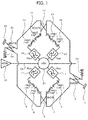
- FIG. 1 is a circuit diagram of the antenna feed circuit according to Embodiment 1 of the present invention.
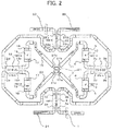
- FIG. 2 is a configuration diagram of the antenna feed circuit according to Embodiment 1 of the present invention.
- the antenna feed circuit includes:
- a high frequency signal output from the waveguide-type low pass filter 7 enters a first branch terminal 21a of a waveguide group branching filter (OMJ) 21 included in a main waveguide 26, a high frequency signal output from the waveguide-type low pass filter 11 enters a second branch terminal 21b of the waveguide group branching filter (OMJ) 21, a high frequency signal output from the waveguide-type low pass filter 16 enters a third branch terminal 21c of the waveguide group branching filter (OMJ) 21, and a high frequency signal output from the waveguide-type low pass filter 20 enters a fourth branch terminal 21d of the waveguide group branching filter (OMJ) 21.
- OMJ waveguide group branching filter
- the first branch terminal 21a, the second branch terminal 21b, the third branch terminal 21c and the fourth branch terminal 21d are arranged, in order, in the outer circumferential direction of the tube wall of the waveguide group branching filter (OMJ) 21 such that the phase difference between adjacent terminals becomes 90°.
- the branch terminals are arranged adjacent to one another, in order, as the first branch terminal 21 a, the second branch terminal 21b, the third branch terminal 21c, the fourth branch terminal 21d and the first branch terminal 21a.
- a horn antenna 30, through the main waveguide 26, is connected to the waveguide group branching filter (OMJ) 21.
- a fourth terminal 12d of the third waveguide-type hybrid circuit 12 is connected to the second terminal 22b, which is a reference phase high frequency signal output terminal of the fourth waveguide-type hybrid circuit 22; and a fourth terminal 3d of the second waveguide-type hybrid circuit 3 is connected to the third terminal 22c of the fourth waveguide-type hybrid circuit 22 and outputs a high frequency signal at the transmission frequency at 90° lagging phase from that of the high frequency signal of the second terminal 22b.
- a first terminal 22a of the fourth waveguide-type hybrid circuit 22 is connected to a second feed terminal 23, which is an additional power feed terminal.
- the mechanical dimensions in the transmission direction of the high frequency signal in the first waveguide-type hybrid circuit 2, second waveguide-type hybrid circuit 3, third waveguide-type hybrid circuit 12 and fourth waveguide-type hybrid circuit 22 are the same, and preferably the same waveguide-type hybrid circuit is used.
- a terminating resistor 24 is connected to the fourth terminal 2d of the first waveguide-type hybrid circuit 2, and a terminating resistor 25 is connected to the fourth terminal 22d of the fourth waveguide-type hybrid circuit 22.
- phase relationships such as reference phase, lagging phase and the like of high frequency signals are described in the explanation of operation, the description concerns phase relationships of the high frequency signal at the transmission frequency.
- the high frequency signal input from the first feed terminal 1 is received as input by the first terminal 2a of the first waveguide-type hybrid circuit 2, and is output from the second terminal 2b at the reference phase and output from the third terminal 2c with 90° lagging phase.
- the high frequency signal output at the reference phase from the second terminal 2b is received as input by the first terminal 3a of the second waveguide-type hybrid circuit 3, and is output from the second terminal 3b at the reference phase and output from the third terminal 3c with 90° lagging phase.
- the high frequency signal output at the reference phase from the second terminal 3b of the second waveguide-type hybrid circuit 3 is received as input by the first waveguide-type polarization converter 4, the polarized wave is output with the polarization rotated by 90° in one direction by the first waveguide-type polarization converter 4, the output high frequency signal is received as input by the second waveguide-type polarization converter 5 through the waveguide 6, the polarized wave is output with the polarization rotated by 90° in another direction opposite to the one direction by the second waveguide-type polarization converter 5, thereby returning to the polarization of the input to the first waveguide-type polarization converter 4 and outputting at the reference phase.
- Rotation of the polarization by 90° by the waveguide-type polarization converters in Embodiment 1 of the present invention means orthogonal rotation of the polarization of the high frequency signal from a horizontal polarization to a vertical polarization. If rotation of the polarization in the clockwise direction is defined, for example, to be rotation in the "one direction”, then rotation of the polarization in the opposite direction (counterclockwise direction) is defined to be rotation in the "other direction”.
- the high frequency signal of the reference phase is output from the second waveguide-type polarization converter 5, harmonics of the high frequencies are removed by the waveguide-type low pass filter 7, and then the filtered high frequency signal enters a first branch terminal 21a of the OMJ 21.
- the high frequency signal having a lagging phase of 90° output from the third terminal 3c of the second waveguide-type hybrid circuit 3 is received as input by the third waveguide-type polarization converter 8, is output with the polarization rotated 90° in the one direction by the third waveguide-type polarization converter 8, enters the fourth waveguide-type polarization converter 9 through the waveguide 10, and is output with the polarization rotated 90° in the other direction by the fourth waveguide-type polarization converter 9 so as to return to the high frequency signal having the polarization that was the polarization of the input to the third waveguide-type polarization converter 8 and to be output at the 90° lagging phase.
- the high frequency signal having the 90° lagging phase output from the third terminal 2c of the first waveguide-type hybrid circuit 2 enters the first terminal 12a of the third waveguide-type hybrid circuit 12, with the 90° lagging phase from the second terminal 12b, is further lagged in phase by 90°, and is thus output from the third terminal 12c with a 180° lagging phase.
- the high frequency signal having the 180° lagging phase output from the third terminal 12c of the third waveguide-type hybrid circuit 12 enters the fifth waveguide-type polarization converter 13, is output with the polarization rotated 90° in the one direction by the fifth waveguide-type polarization converter 13, and enters the sixth waveguide-type polarization converter 14 through the waveguide 15, and the polarization is rotated by 90° in the other direction by the sixth waveguide-type polarization converter 14, so as to return to high frequency signal having the polarization that was the polarization of the input to the fifth waveguide-type polarization converter 13 and to be output with the 180° lagging phase.
- the resultant high frequency signal enters the third branch terminal 21c of the OMJ 21.
- the high frequency signal having the 90° lagging phase output from the second terminal 12b of the third waveguide-type hybrid circuit 12 enters the seventh waveguide-type polarization converter 17, is output with the polarization rotated by 90° in the other direction by the seventh waveguide-type polarization converter 17, enters the eighth waveguide-type polarization converter 18 through the waveguide 19, and is further rotated by 90° in the other direction by the eighth waveguide-type polarization converter 18, so that the resultant polarization has 180° symmetry relative to the polarization of the high frequency signal that entered seventh waveguide-type polarization converter 17, and thus the output high frequency signal has a 270° lagging phase.
- the high frequency signals having progressively 90° lagging phase in order, as the signals entering the first branch terminal 21a, the second branch terminal 21b, the third branch terminal 21c and the fourth branch terminal 21d of the OMJ 21, enter the OMJ 21, and thus a circularly polarized wave is generated by the OMJ 21.
- Phase lags in the counterclockwise direction in FIG. 2 and thus as viewed from the plane of the paper, a counterclockwise circularly polarized wave is generated.
- the high frequency signal of the reference phase enters the third branch terminal 21c
- the high frequency signal at 90° lagging phase enters the second branch terminal 21b
- the high frequency signal at 180° lagging phase enters the first branch terminal 21 a
- the high frequency signal at 270° lagging phase enters the fourth branch terminal 21d of the OMJ 21. Due to the high frequency signals entering the OMJ 21, phase becomes lagged in the clockwise direction as seen in FIG. 2 , and a circularly polarized wave is generated with clockwise circular polarization.
- the operation of generating the circularly polarized wave with clockwise circular polarization is explained below.
- the high frequency signal input from the second feed terminal 23 enters the first terminal 22a of the fourth waveguide-type hybrid circuit 22, is output from the second terminal 22b at the reference phase, and is output from the third terminal 22c with a 90° lagging phase.
- the high frequency signal output at the reference phase from the second terminal 22b enters the fourth terminal 12d of the third waveguide-type hybrid circuit 12, is output from the third terminal 12c at the reference phase, and is output from the second terminal 12b with a 90° lagging phase.
- the high frequency signal output at the reference phase from the third terminal 12c of the third waveguide-type hybrid circuit 12 enters the fifth waveguide-type polarization converter 13, is output with the polarization rotated by 90 degrees in the one direction by the fifth waveguide-type polarization converter 13, enters the sixth waveguide-type polarization converter 14 through the waveguide 15, and the polarization is rotated by 90° in the other direction by the sixth waveguide-type polarization converter 14, so as to return to the polarization of the input to the fifth waveguide-type polarization converter 13, and the high frequency signal is output at the reference phase.
- the harmonics of the high frequency signal at the reference phase output from the sixth waveguide-type polarization converter 14 are removed by the waveguide-type low pass filter 16, and the resultant high frequency signal enters the third branch terminal 21c of the OMJ 21.
- the high frequency signal output at with the 90° lagging phase from the second terminal 12b of the third waveguide-type hybrid circuit 12 enters the seventh waveguide-type polarization converter 17, is output with the polarization rotated by 90° in the other direction by the seventh waveguide-type polarization converter 17, enters the eighth waveguide-type polarization converter 18 through the waveguide 19, and is rotated further by 90° in the other direction by the eighth waveguide-type polarization converter 18, resulting in a polarization that has 180° symmetry relative to the high frequency signal entering the eighth waveguide-type polarization converter 17, and thus the high frequency signal is output at 270° lagging phase.
- the high frequency signal After removal of the harmonics by the waveguide-type low pass filter 20 from the high frequency signal at 270° lagging phase output from the eighth waveguide-type polarization converter 18, the high frequency signal enters the fourth branch terminal 21d of the OMJ 21.
- the high frequency signal having the 90° lagging phase output from the third terminal 22c of the fourth waveguide-type hybrid circuit 22 enters the fourth terminal 3d of the second waveguide-type hybrid circuit 3, and is output at the same 90° lagging phase from the third terminal 3c, the high frequency signal is further lagged in phase by 90°, so that the high frequency signal at 180° lagging phase is output from the second terminal 3b.
- the high frequency signal at the 180° lagging phase output from the second terminal 3b of the second waveguide-type hybrid circuit 3 enters the first waveguide-type polarization converter 4, is output with the polarization rotated by 90° in the one direction by the first waveguide-type polarization converter 4, enters the second waveguide-type polarization converter 5 through the waveguide 6, and is output with the polarization rotated by 90° in the other direction by the second waveguide-type polarization converter 5, so that the polarization returns to that of the input to the first waveguide-type polarization converter 4, and the high frequency signal is output at the same 180° lagging phase.
- the high frequency signal After removal of the harmonics by the waveguide-type low pass filter 7 from the high frequency signal at the 180° lagging phase output from the second waveguide-type polarization converter 5, the high frequency signal enters the first branch terminal 21a of the OMJ 21.
- the high frequency signal at the 90° lagging phase output from the third terminal 3c of the second waveguide-type hybrid circuit 3 enters the third waveguide-type polarization converter 8, is output with the polarization rotated by 90° in the one direction by the third waveguide-type polarization converter 8, enters the fourth waveguide-type polarization converter 9 through the waveguide 10, and is output with the polarization rotated by 90° in the other direction by the fourth waveguide-type polarization converter 9, so that the polarization returns to that of the input to the third waveguide-type polarization converter 8, and the high frequency signal is output with the same 90° lagging phase.
- the high frequency signal After removal of the harmonics by the waveguide-type low pass filter 11 from the high frequency signal having the 90° lagging phase output from the fourth waveguide-type polarization converter 9, the high frequency signal enters the second branch terminal 21b of the OMJ 21.
- the high frequency signals having progressively 90° lagging phase in order, as the signals entering the third branch terminal 21c, the second branch terminal 21b, the first branch terminal 21a and the fourth branch terminal 21d of the OMJ 21, enter the OMJ 21, and thus a circularly polarized wave is generated by the OMJ 21.
- Phase lags in the clockwise direction in FIG. 2 and thus as viewed from the plane of the paper, a clockwise circularly polarized wave is generated.
- the antenna feed circuit according to Embodiment 1 of the present invention rather than enabling change of phase of the high frequency signal using phase shifters, enables rotation of the polarization of the high frequency signal by use of waveguide-type polarization converters such as the waveguide-type polarization converter described in Japanese Patent JP 3 884 725 B2 , twist waveguide and the like.
- the antenna feed circuit of Embodiment 1 is advantageous due to wide band frequency characteristic of the high frequency signal in comparison to the configuration using phase shifters.
- the antenna feed circuit is two-dimensional and has the advantage of enabling reduction of thickness of the antenna feed circuit.
- the antenna feed circuit of Embodiment 1 of the present invention is configured using the first through fourth waveguide-type hybrid circuits, the first through eighth waveguide-type polarization converters, the waveguide-type low pass filters and the waveguides, which are passive components. Therefore reverse operation is possible, and when a clockwise circularly polarized wave high frequency signal enters the OMJ 21, the high frequency signal is output from the second feed terminal, and when a counterclockwise circularly polarized wave high frequency signal enters the OMJ 21, the high frequency signal is output from the first feed terminal.
- the sequence of rotations may begin with either clockwise rotation or counterclockwise rotation.
- the relationship of rotation direction of the polarization of the high frequency signals of the third waveguide-type polarization converter 8 and the fourth waveguide-type polarization converter 9 is similar to the relationship of rotation direction of the polarization of the high frequency signals of the fifth waveguide-type polarization converter 13 and the sixth waveguide-type polarization converter 14.
- the rotation direction can be either clockwise or counterclockwise, as long as the polarization of the eighth waveguide-type polarization converter 18 has the same direction of rotation of the polarization of the seventh waveguide-type polarization converter 17 such that the polarization of the high frequency signal output from the eighth waveguide-type polarization converter 18 has rotation 180° opposite to the polarization of the high frequency signal entering the seventh waveguide-type polarization converter 17.
- a circularly polarized wave is generated by feeding the high frequency signal phase lagged in increments of 90° into the OMJ 21 arranged in the main waveguide.
- the circularly polarized wave may also be generated by arranging an orthogonal polarized wave separator (OMT), rather than the OMJ 21, in the main waveguide, and receiving as input the high frequency signal to the OMT phase lagged in increments of 90°.
- OMT orthogonal polarized wave separator
- FIGS. 3 and 4 An antenna feed circuit of Embodiment 2 of the present invention is described with reference to FIGS. 3 and 4 .
- constituent elements that are the same or equivalent to those of FIGS. 1 and 2 are assigned the same reference signs, and description of such elements is omitted.
- the waveguide-type low pass filter 7, waveguide-type low pass filter 11, waveguide-type low pass filter 16 and waveguide-type low pass filter 20 from the antenna feed circuit of Embodiment 1 of the present invention are omitted, and an orthogonal polarized wave separator (OMT) 40 is arranged in the main waveguide 26 in place of the waveguide group branching filter (OMJ) 21.
- OMT orthogonal polarized wave separator
- the high frequency signal output from the second waveguide-type polarization converter 5 enters the first branch terminal 40a of the orthogonal polarized wave separator (OMT) 40 arranged in the main waveguide 26, the high frequency signal output from the fourth waveguide-type polarization converter 9 enters the second branch terminal 40b of the orthogonal polarized wave separator (OMT) 40, the high frequency signal output from the sixth waveguide-type polarization converter 14 enters the third branch terminal 40c of the orthogonal polarized wave separator (OMT) 40, and the high frequency signal output from the eighth waveguide-type polarization converter 18 enters the fourth branch terminal 40d of the orthogonal polarized wave separator (OMT) 40.
- OMT orthogonal polarized wave separator
- the first branch terminal 40a, second branch terminal 40b, third branch terminal 40c and fourth branch terminal 40d are arranged at the orthogonal polarized wave separator (OMT) 40 so that the phase differences between adjacent terminals become 90°. Furthermore, the branch terminals are arranged adjacent to each other, in order, as the first branch terminal 40a, second branch terminal 40b, third branch terminal 40c, fourth branch terminal 40d, and first branch terminal 40a.
- the horn antenna 30 is connected through the main waveguide 26 to the orthogonal polarized wave separator (OMT) 40.
- phase relationships of high frequency signals such as reference phase, lagging phase and the like, are described in the explanation of operation, the description concerns phase relationships that are all of the high frequency signals at the transmission frequency.
- the high frequency signal input from the first feed terminal 1 enters the first terminal 2a of the first waveguide-type hybrid circuit 2, and is output respectively at the reference phase from the second terminal 2b, and at 90° lagging phase from the third terminal 2c.
- the high frequency signal output at the reference phase from the second terminal 2b enters the first terminal 3a of the second waveguide-type hybrid circuit 3, and is output respectively at the reference phase from the second terminal 3b and at 90° lagging phase from the third terminal 3c.
- the high frequency signal output at the reference phase from the second terminal 3b of the second waveguide-type hybrid circuit 3 enters the first waveguide-type polarization converter 4, from which the polarized wave is output with the polarization rotated by 90° in the one direction by the first waveguide-type polarization converter 4, and enters the second waveguide-type polarization converter 5 through the waveguide 6, and the polarization is rotated by the second waveguide-type polarization converter 5 by 90° in the other direction opposite to the one direction, and thus phase of the polarization returns to that entering the first waveguide-type polarization converter 4, and the high frequency signal is output at the reference phase.
- the rotation of the polarization by 90° by the waveguide-type polarization converters in Embodiment 1 of the present invention means orthogonal rotation of the polarization of the high frequency signal from a horizontal polarization to a vertical polarization.
- Rotation in the one direction and rotation in the other direction are defined, for example, such that propagation of the high frequency signal is taken to be rotated in the one direction by clockwise rotation, and is taken to be rotated in the other direction by counterclockwise rotation.
- the high frequency signal of the reference phase output from the second waveguide-type polarization converter 5 enters the first branch terminal 40a of the OMT 40.
- the high frequency signal output at 90° lagging phase output from the third terminal 3c of the second waveguide-type hybrid circuit 3 enters the third waveguide-type polarization converter 8, from which the polarized wave is output with the polarization rotated by 90° in the one direction by the third waveguide-type polarization converter 8, and enters the fourth waveguide-type polarization converter 9 through the waveguide 10.
- the high frequency signal polarization is rotated by 90° in the other direction by the fourth waveguide-type polarization converter 9, and thus polarization returns to that of the input to the third waveguide-type polarization converter 8, and is output at the same 90° lagging phase.
- the high frequency signal at the 90° lagging phase output from the fourth waveguide-type polarization converter 9 enters the second branch terminal 40b of the OMT 40.
- the high frequency signal having the 90° lagging phase output from the third terminal 2c of the first waveguide-type hybrid circuit 2 enters the first terminal 12a of the third waveguide-type hybrid circuit 12, is output at the same 90° lagging phase from the second terminal 12b and is output from the third terminal 12c further lagged in phase by 90°, that is to say, is output at 180° lagging phase.
- the high frequency signal at the 180° lagging phase output from the third terminal 12c of the third waveguide-type hybrid circuit 12 enters the fifth waveguide-type polarization converter 13, is output after rotation of the polarization by 90° in the one direction by the fifth waveguide-type polarization converter 13, and enters the sixth waveguide-type polarization converter 14 through the waveguide 15, and the polarization is rotated by 90° in the other direction by the sixth waveguide-type polarization converter 14, which returns the polarization to the polarization of the input to the fifth waveguide-type polarization converter 13, so that the high frequency signal is output at the same 180° lagging phase.
- the high frequency signal at the 180° lagging phase output from the sixth waveguide-type polarization converter 14 enters the third branch terminal 40c of the OMT 40.
- the high frequency signal at the 90° lagging phase output from the second terminal 12b of the third waveguide-type hybrid circuit 12 enters the seventh waveguide-type polarization converter 17, is output after rotation of the polarization by 90° in the other direction by the seventh waveguide-type polarization converter 17, and enters the eighth waveguide-type polarization converter 18 through the waveguide 19, and the polarization is further rotated by 90° in the other direction by the eighth waveguide-type polarization converter 18, which makes the polarization 180° opposite in polarization to that of the input to the seventh waveguide-type polarization converter 17, so that the high frequency signal is output at 270° lagging phase.
- the high frequency signal at the 270° lagging phase output from the eighth waveguide-type polarization converter 18 enters the fourth branch terminal 40d of the OMT 40.
- the high frequency signals having progressively 90° lagging phase in order, as the signals entering the first branch terminal 40a, the second branch terminal 40b, the third branch terminal 40c and the fourth branch terminal 40d of the OMT 40, enter the OMT 40, and thus a circularly polarized wave is generated by the OMT 40.
- Phase lags in the counterclockwise direction in FIG. 4 and thus as viewed from the plane of the paper, a counterclockwise circularly polarized wave is generated.
- the high frequency signal enters the second feed terminal 23, by similar operation, the high frequency signal of the reference phase entering the third branch terminal 40c of the OMT40, the high frequency signal at the 90° lagging phase entering the second branch terminal 40b, the high frequency signal at the 180° lagging phase entering the first branch terminal 40a, and the high frequency signal at the 270° lagging phase entering the fourth branch terminal 40d enter the OMT 40.
- phase lags in the clockwise direction in FIG. 4 and therefore as viewed from the plane of the paper, a clockwise circularly polarized wave is generated.
- the high frequency signal input from the second feed terminal 23 enters the first terminal 22a of the fourth waveguide-type hybrid circuit 22, and is output respectively at the reference phase from the second terminal 22b and at 90° lagging phase from the third terminal 22c.
- the high frequency signal output at the reference phase from the second terminal 22b enters the fourth terminal 12d of the third waveguide-type hybrid circuit 12, and is output respectively from the third terminal 12c at the reference phase and from the second terminal 12b at 90° lagging phase.
- the high frequency signal output at the reference phase from the third terminal 12c of the third waveguide-type hybrid circuit 12 enters the fifth waveguide-type polarization converter 13, is output with the polarization rotated by 90° in the one direction by the fifth waveguide-type polarization converter 13, enters the sixth waveguide-type polarization converter 14 through the waveguide 15, and has the polarization rotated 90° in the other direction by the sixth waveguide-type polarization converter 14, so that the polarization returns to that of the input to the fifth waveguide-type polarization converter 13, and the high frequency signal is output at the reference phase.
- the high frequency signal of the reference phase output from the sixth waveguide-type polarization converter 14 enters the third branch terminal 40c of the OMT 40.
- the high frequency signal at the 90° lagging phase output from the second terminal 12b of the third waveguide-type hybrid circuit 12 enters the seventh waveguide-type polarization converter 17, is output after rotation of the polarization by 90° in the other direction by the seventh waveguide-type polarization converter 17, and enters the eighth waveguide-type polarization converter 18 through the waveguide 19, and the polarization is further rotated by 90° in the other direction by the eighth waveguide-type polarization converter 18, so that the resultant polarization is 180° opposite to the polarization of the input to the seventh waveguide-type polarization converter 17, and thus the high frequency signal is output at 270° lagging phase.
- the high frequency signal at the 270° lagging phase output from the eighth waveguide-type polarization converter 18 enters the fourth branch terminal 40d of the OMT 40.
- the high frequency signal at the 180° lagging phase output from the second terminal 3b of the second waveguide-type hybrid circuit 3 enters the first waveguide-type polarization converter 4, is output after rotation of the polarization by 90° in the one direction by the first waveguide-type polarization converter 4, and enters the second waveguide-type polarization converter 5 through the waveguide 6, and the second waveguide-type polarization converter 5 rotates the polarization by 90° in the other direction to return to the input polarization of the first waveguide-type polarization converter 4, and the high frequency signal is output at 180° lagging phase.
- the high frequency signal at the 180° lagging phase output from the second waveguide-type polarization converter 5 enters the first branch terminal 40a of the OMT 40.
- the high frequency signal at the 90° lagging phase output from the third terminal 3c of the second waveguide-type hybrid circuit 3 enters the third waveguide-type polarization converter 8, is output after rotation of the polarization by 90° in the one direction by the third waveguide-type polarization converter 8, and enters the fourth waveguide-type polarization converter 9 through the waveguide 10, and the polarization is rotated by 90° in the other direction by the fourth waveguide-type polarization converter 9, so that the resultant polarization returns to the polarization of the input to the third waveguide-type polarization converter 8, and thus the high frequency signal is output at the same 90° lagging phase.
- the high frequency signal at the 90° lagging phase output from the fourth waveguide-type polarization converter 9 enters the second branch terminal 40b of the OMT 40.
- the high frequency signals having progressively incremented 90° lagging phase in order, as the signals entering the third branch terminal 40c, the second branch terminal 40b, the first branch terminal 40a and the fourth branch terminal 40d of the OMT 40, enter the OMT 40, and thus a circularly polarized wave is generated by the OMT 40.
- Phase lags in the clockwise direction in FIG. 4 and thus as viewed from the plane of the paper, a clockwise circularly polarized wave is generated.
- the antenna feed circuit of Embodiment 2 of the present invention causes rotation of the polarization of the high frequency signal by use of waveguide-type polarization converters such as the waveguide-type polarization converter described in Japanese Patent JP 3 884 725 B2 , twist waveguide and the like, and thus the antenna feed circuit is advantageous in that the frequency characteristic of the high frequency signal has a wider band region than that of the configuration using phase shifters.
- the antenna feed circuit has a two dimensional structure, and is advantageous due to the ability to reduce thickness of the antenna feed circuit.
- the antenna feed circuit of Embodiment 2 of the present invention is configured using the first through fourth waveguide-type hybrid circuits, the first through eighth waveguide-type polarization converters and the waveguides, which are passive elements, and thus reverse operation is possible, so that a high frequency signal is output from the second feed terminal when a clockwise circular rotation polarization high frequency signal enters the OMT 40, and a high frequency signal is output from the first feed terminal when a counterclockwise circular rotation polarization high frequency signal enters the OMT 40.
- the order of rotation of the polarization may start with either clockwise rotation or with counterclockwise rotation.
- the relationship between the rotation directions of the polarization according to the third waveguide-type polarization converter 8 and the fourth waveguide-type polarization converter 9 is the same as the relationship between the rotation directions of the polarization according to the fifth waveguide-type polarization converter 13 and the sixth waveguide-type polarization converter 14.
- the rotation directions of the polarization may be clockwise or counterclockwise.
- the angles of rotation of the polarization of the first waveguide-type polarization converter 4 through the eighth waveguide-type polarization converter 18 are set at 90°.
- these angles of rotation of the polarization are not restricted to 90°, as long as the absolute values of the angles of rotation of the first waveguide-type polarization converter 4 and the second waveguide-type polarization converter 5 are the same, and the rotation directions of the polarization are mutually opposite.
- the angle of rotation of the first waveguide-type polarization converter 4 is clockwise by 45°
- the angle of rotation of the second waveguide-type polarization converter 5 may be counterclockwise by 45°.
- the relationships of the angles of rotation and the rotation directions of the polarization of the third waveguide-type polarization converter 8 and the fourth waveguide-type polarization converter 9 are the same as the relationships of the angles of rotation and the rotation directions of the polarization of the fifth waveguide-type polarization converter 13 and the sixth waveguide-type polarization converter 14.
- the absolute values of the angles of rotation of polarization of the first waveguide-type polarization converter 4 through the sixth waveguide-type polarization converter 14 are the same, as long as the absolute values of angles of rotation of the polarization of the first waveguide-type polarization converter 4 and second waveguide-type polarization converter 5 pair are the same, the absolute values of angles of rotation of the polarization of the third waveguide-type polarization converter 8 and fourth waveguide-type polarization converter 9 pair are the same, and the absolute values of angles of rotation of the polarization of the fifth waveguide-type polarization converter 13 and sixth waveguide-type polarization converter 14 pair are the same.
- the seventh waveguide-type polarization converter 17 and eighth waveguide-type polarization converter 18 Concerning the relationship between the seventh waveguide-type polarization converter 17 and eighth waveguide-type polarization converter 18, as long as the directions of rotation of the polarization of the seventh waveguide-type polarization converter 17 and eighth waveguide-type polarization converter 18 are the same, and the polarization of the high frequency signal output from the eighth waveguide-type polarization converter 18 is 180° reversed from the polarization of the high frequency signal input to the seventh waveguide-type polarization converter 17, there is no requirement for the absolute values of the rotation angles of the polarization of the seventh waveguide-type polarization converter 17 and eighth waveguide-type polarization converter 18 to be identical. For example, if the rotation angle of the polarization of the seventh waveguide-type polarization converter 17 is 45° clockwise, then the rotation angle of the polarization of the eighth waveguide-type polarization converter 18 may be 135° clockwise.
- FIG. 5 A circuit diagram of the antenna feed circuit of Embodiment 3 of the present invention is shown in FIG. 5 , in which the absolute values of the angles of rotation of the polarization of the first waveguide-type polarization converter 4 through the seventh waveguide-type polarization converter 17 of the antenna feed circuit of Embodiment 2 of the present invention are set to 45°, and the absolute value of the angle of rotation of the polarization of the eighth waveguide-type polarization converter 18 is set to 135°.
- the operation of the antenna feed circuit of Embodiment 3 of the present invention is the same as that of the antenna feed circuit of Embodiment 2 of the present invention, except that the absolute values of the angles of rotation of the polarization of the first waveguide-type polarization converter 4 through the eighth waveguide-type polarization converter 18 differ from those of the antenna feed circuit of Embodiment 2 of the present invention.
- the antenna feed circuit is the same as that of Embodiment 1 of the present invention, except for the absolute values of the angles of rotation of the first waveguide-type polarization converter 4 through the eighth waveguide-type polarization converter 18 being different from those of the antenna feed circuit of Embodiment 1 of the present invention.
- the first waveguide-type hybrid circuit 2, second waveguide-type hybrid circuit 3, third waveguide-type hybrid circuit 12 and fourth waveguide-type hybrid circuit 22 may be either a branch-line type 90° waveguide-type hybrid circuit or a short-slot type 90° waveguide-type hybrid circuit.
Landscapes
- Waveguide Switches, Polarizers, And Phase Shifters (AREA)
- Aerials With Secondary Devices (AREA)
Applications Claiming Priority (2)
| Application Number | Priority Date | Filing Date | Title |
|---|---|---|---|
| JP2013259690 | 2013-12-17 | ||
| PCT/JP2014/083235 WO2015093466A1 (ja) | 2013-12-17 | 2014-12-16 | アンテナ給電回路 |
Publications (2)
| Publication Number | Publication Date |
|---|---|
| EP3086401A1 true EP3086401A1 (de) | 2016-10-26 |
| EP3086401A4 EP3086401A4 (de) | 2017-07-26 |
Family
ID=53402812
Family Applications (1)
| Application Number | Title | Priority Date | Filing Date |
|---|---|---|---|
| EP14870911.6A Withdrawn EP3086401A4 (de) | 2013-12-17 | 2014-12-16 | Antennen-stromversorgungsschaltung |
Country Status (4)
| Country | Link |
|---|---|
| US (1) | US9559413B2 (de) |
| EP (1) | EP3086401A4 (de) |
| JP (1) | JP5832706B1 (de) |
| WO (1) | WO2015093466A1 (de) |
Families Citing this family (4)
| Publication number | Priority date | Publication date | Assignee | Title |
|---|---|---|---|---|
| JP6785631B2 (ja) * | 2016-12-05 | 2020-11-18 | 三菱電機株式会社 | アンテナ給電回路 |
| US11710907B1 (en) * | 2020-01-09 | 2023-07-25 | Lockheed Martin Corporation | Clone carousel waveguide feed network |
| WO2022024318A1 (ja) * | 2020-07-30 | 2022-02-03 | 三菱電機株式会社 | 導波管カプラ |
| US12230876B1 (en) * | 2022-11-07 | 2025-02-18 | Lockheed Martin Corporation | Integrated microwave radio frequency feed network |
Family Cites Families (8)
| Publication number | Priority date | Publication date | Assignee | Title |
|---|---|---|---|---|
| JP2001016128A (ja) * | 1999-06-30 | 2001-01-19 | Maspro Denkoh Corp | 2衛星受信アンテナ用コンバータ |
| WO2002069449A1 (fr) * | 2001-02-26 | 2002-09-06 | Mitsubishi Denki Kabushiki Kaisha | Dispositif d'antenne |
| US6661309B2 (en) * | 2001-10-22 | 2003-12-09 | Victory Industrial Corporation | Multiple-channel feed network |
| JP3884725B2 (ja) | 2003-06-03 | 2007-02-21 | 三菱電機株式会社 | 導波管装置 |
| JP4827804B2 (ja) | 2007-07-23 | 2011-11-30 | 三菱電機株式会社 | アンテナ給電回路 |
| DE102008044895B4 (de) * | 2008-08-29 | 2018-02-22 | Astrium Gmbh | Signal-Verzweigung zur Verwendung in einem Kommunikationssystem |
| US8013784B2 (en) * | 2009-03-03 | 2011-09-06 | Toyota Motor Engineering & Manufacturing North America, Inc. | Butler matrix for 3D integrated RF front-ends |
| JP5822635B2 (ja) | 2011-10-07 | 2015-11-24 | 三菱電機株式会社 | アンテナ給電回路 |
-
2014
- 2014-12-16 WO PCT/JP2014/083235 patent/WO2015093466A1/ja not_active Ceased
- 2014-12-16 US US15/104,162 patent/US9559413B2/en not_active Expired - Fee Related
- 2014-12-16 JP JP2015524543A patent/JP5832706B1/ja active Active
- 2014-12-16 EP EP14870911.6A patent/EP3086401A4/de not_active Withdrawn
Also Published As
| Publication number | Publication date |
|---|---|
| US9559413B2 (en) | 2017-01-31 |
| US20160315382A1 (en) | 2016-10-27 |
| WO2015093466A1 (ja) | 2015-06-25 |
| EP3086401A4 (de) | 2017-07-26 |
| JPWO2015093466A1 (ja) | 2017-03-16 |
| JP5832706B1 (ja) | 2015-12-16 |
Similar Documents
| Publication | Publication Date | Title |
|---|---|---|
| EP3086401A1 (de) | Antennen-stromversorgungsschaltung | |
| JPS5937602B2 (ja) | 周波数2重利用分波装置 | |
| JP5822635B2 (ja) | アンテナ給電回路 | |
| KR20120017452A (ko) | 합성 우/좌향 위상-선도/지연 라인들을 이용한 다이플렉서 합성 | |
| US10763593B1 (en) | Broadband single pol TX, dual pol RX, circular polarization waveguide network | |
| US9178285B2 (en) | Phase shift device and method | |
| JP6865903B2 (ja) | 給電回路 | |
| Navarrini et al. | Design of a dual polarization SIS sideband separating receiver based on waveguide OMT for the 275–370 GHz frequency band | |
| KR101491723B1 (ko) | 커플러를 이용한 이중 대역 피드혼 | |
| JP6316076B2 (ja) | 偏分波器 | |
| JP4903100B2 (ja) | 導波管形電力合成分配器およびそれを用いたアレーアンテナ装置 | |
| JP6161345B2 (ja) | 偏波分離回路 | |
| Baena et al. | Linear to circular polarization converters based on self-complementary metasurfaces | |
| JPH0322081B2 (de) | ||
| WO2016027387A1 (ja) | 電界方向変換構造及び平面アンテナ | |
| CA2915266C (en) | Orthogonal-mode junction coupler and associated polarization and frequency separator | |
| JP2555925B2 (ja) | 回転型導波管結合器およびアンテナ給電装置 | |
| US11056759B2 (en) | Hybrid coupler with sum and difference ports located on the same side | |
| US20140199026A1 (en) | Waveguide power combiner/splitter | |
| WO2017094817A1 (ja) | 周波数混合器および中間周波数信号生成方法 | |
| JP6253342B2 (ja) | 偏波分離回路 | |
| JPH1051208A (ja) | 分波器 | |
| JPS6130761B2 (de) | ||
| JP2009284148A (ja) | アンテナ共用装置及び周波数分離装置及び帯域通過フィルタ装置 | |
| JP2006246368A (ja) | 偏波共用帯域分波器 |
Legal Events
| Date | Code | Title | Description |
|---|---|---|---|
| PUAI | Public reference made under article 153(3) epc to a published international application that has entered the european phase |
Free format text: ORIGINAL CODE: 0009012 |
|
| 17P | Request for examination filed |
Effective date: 20160614 |
|
| AK | Designated contracting states |
Kind code of ref document: A1 Designated state(s): AL AT BE BG CH CY CZ DE DK EE ES FI FR GB GR HR HU IE IS IT LI LT LU LV MC MK MT NL NO PL PT RO RS SE SI SK SM TR |
|
| AX | Request for extension of the european patent |
Extension state: BA ME |
|
| DAX | Request for extension of the european patent (deleted) | ||
| A4 | Supplementary search report drawn up and despatched |
Effective date: 20170627 |
|
| RIC1 | Information provided on ipc code assigned before grant |
Ipc: H01P 1/161 20060101AFI20170621BHEP Ipc: H01Q 1/50 20060101ALI20170621BHEP |
|
| STAA | Information on the status of an ep patent application or granted ep patent |
Free format text: STATUS: THE APPLICATION HAS BEEN WITHDRAWN |
|
| 18W | Application withdrawn |
Effective date: 20191213 |