EP3086442A1 - Machine électrique doté d'une première partie active et d'une seconde partie active - Google Patents
Machine électrique doté d'une première partie active et d'une seconde partie active Download PDFInfo
- Publication number
- EP3086442A1 EP3086442A1 EP15164650.2A EP15164650A EP3086442A1 EP 3086442 A1 EP3086442 A1 EP 3086442A1 EP 15164650 A EP15164650 A EP 15164650A EP 3086442 A1 EP3086442 A1 EP 3086442A1
- Authority
- EP
- European Patent Office
- Prior art keywords
- active part
- winding
- segment
- connection element
- connection
- Prior art date
- Legal status (The legal status is an assumption and is not a legal conclusion. Google has not performed a legal analysis and makes no representation as to the accuracy of the status listed.)
- Granted
Links
Images


Classifications
-
- H—ELECTRICITY
- H02—GENERATION; CONVERSION OR DISTRIBUTION OF ELECTRIC POWER
- H02K—DYNAMO-ELECTRIC MACHINES
- H02K3/00—Details of windings
- H02K3/04—Windings characterised by the conductor shape, form or construction, e.g. with bar conductors
- H02K3/12—Windings characterised by the conductor shape, form or construction, e.g. with bar conductors arranged in slots
-
- H—ELECTRICITY
- H02—GENERATION; CONVERSION OR DISTRIBUTION OF ELECTRIC POWER
- H02K—DYNAMO-ELECTRIC MACHINES
- H02K7/00—Arrangements for handling mechanical energy structurally associated with dynamo-electric machines, e.g. structural association with mechanical driving motors or auxiliary dynamo-electric machines
- H02K7/18—Structural association of electric generators with mechanical driving motors, e.g. with turbines
- H02K7/1807—Rotary generators
- H02K7/1823—Rotary generators structurally associated with turbines or similar engines
- H02K7/183—Rotary generators structurally associated with turbines or similar engines wherein the turbine is a wind turbine
- H02K7/1838—Generators mounted in a nacelle or similar structure of a horizontal axis wind turbine
-
- H—ELECTRICITY
- H02—GENERATION; CONVERSION OR DISTRIBUTION OF ELECTRIC POWER
- H02K—DYNAMO-ELECTRIC MACHINES
- H02K2201/00—Specific aspects not provided for in the other groups of this subclass relating to the magnetic circuits
- H02K2201/15—Sectional machines
-
- H—ELECTRICITY
- H02—GENERATION; CONVERSION OR DISTRIBUTION OF ELECTRIC POWER
- H02K—DYNAMO-ELECTRIC MACHINES
- H02K2213/00—Specific aspects, not otherwise provided for and not covered by codes H02K2201/00 - H02K2211/00
- H02K2213/12—Machines characterised by the modularity of some components
-
- Y—GENERAL TAGGING OF NEW TECHNOLOGICAL DEVELOPMENTS; GENERAL TAGGING OF CROSS-SECTIONAL TECHNOLOGIES SPANNING OVER SEVERAL SECTIONS OF THE IPC; TECHNICAL SUBJECTS COVERED BY FORMER USPC CROSS-REFERENCE ART COLLECTIONS [XRACs] AND DIGESTS
- Y02—TECHNOLOGIES OR APPLICATIONS FOR MITIGATION OR ADAPTATION AGAINST CLIMATE CHANGE
- Y02E—REDUCTION OF GREENHOUSE GAS [GHG] EMISSIONS, RELATED TO ENERGY GENERATION, TRANSMISSION OR DISTRIBUTION
- Y02E10/00—Energy generation through renewable energy sources
- Y02E10/70—Wind energy
- Y02E10/72—Wind turbines with rotation axis in wind direction
Definitions
- the present invention relates to an electrical machine having a first active part and a second active part.
- the second active part in the direction of movement is movable relative to the first active part.
- the first active part comprises at least a first active part segment and at least one second active part segment.
- the first active part has at least one winding, which comprises a first winding section and a second winding section.
- the first active part segment has grooves in which the first winding section is arranged.
- the second active part segment has grooves, in which the second winding section is arranged.
- Electric machines and motors, generators and transformers each have one or more active parts that are magnetically active.
- a motor for example, has a stator and a rotor as the respective active part.
- stator and / or rotor of a motor or generator coils may be inserted or wrapped.
- the coils are then in or on a laminated core or iron package.
- the coils protrude out of the end winding sides of the cylindrical or hollow-cylindrical laminations and form a winding overhang of the rotor or stator.
- the sheet packages or iron packages are segmented due to the workability and portability.
- Such generators of large size are used for example in wind turbines.
- Segmented iron packages or laminated cores are used for example in generators of a wind turbine.
- this segmentability offers for the winding technology some disadvantages.
- For segmented laminated cores the use of two-layer windings is not possible. This then leads to special measures, such as lobes or single-layer windings. If, for example, hinged-coil two-layer windings are used, then it is necessary when installing the segments of a complex coil installation and coil insulation. Furthermore, the exchange of defective segments is very time consuming and costly.
- monolayer windings are used instead of flap-coil two-layer windings, the coil dimensions are very large and different coil shapes are necessary.
- the object of the invention is to make a winding of an electrical machine with a segmented active part particularly efficient and designed.
- an electric machine having a first active part and a second active part.
- the second active part in the direction of movement is movable relative to the first active part.
- the first active part is arranged stationary to the second active part.
- the first active part comprises at least a first active part segment and at least one second active part segment.
- the active part may also comprise more than two active part segments. By segments is meant here that the laminated core of the first active part is segmented relative to the direction of movement of the second active part.
- the first active part has at least one winding, which comprises a first winding section and a second winding section.
- the first active part segment has grooves in which the first winding section is arranged.
- the second active segment has grooves in which the second winding section is arranged.
- the winding system of the first active part thus has, for example, a single winding.
- the winding may comprise a plurality of conductors associated with a phase.
- a winding can therefore have several phases.
- this winding can be divided into winding segments, ie winding sections. That is, the at least one winding is composed of the first winding section and the second winding section.
- the winding would be divided into three winding sections.
- a winding section is thus a section of the at least one winding, which is arranged in the grooves of the respective active part segment.
- the first active part segment and the second active part segment may comprise a laminated core segment or an iron core segment having grooves.
- a first winding section or a second winding section is inserted in the grooves of the respective laminated core segment or iron core segment.
- the first winding section further has a first connection element, which is arranged on a first end side of the first active part segment.
- the second winding section has a second connection element, which is arranged on a second end face of the second active part segment.
- connecting element is meant, for example, an end region of the first and second winding section.
- the connection element is part of the respective winding section.
- the first and the second winding section have an end region which can project on the respective winding head side of the respective active part segment.
- the connection element of the winding section like a winding overhang of the winding section on a winding side, can protrude out of a groove of the active part segment.
- first end side of the first active part segment and the second end side of the second active part segment are arranged adjacent to one another.
- the first end side of the first active part segment and the second end side of the second active segment segment are arranged substantially perpendicular to the direction of movement of the second active segment segment and parallel to one another.
- front side of the active part segment is meant, for example, the surface which extends at one end of the active part segment or laminated core segment perpendicular to the main extension direction of the active part segment or laminated core segment.
- first connection element and the second connection element are arranged next to one another. In other words, the first active part segment and the second active part segment are associated with each other.
- the first active part of the electric machine may also comprise a plurality of active part segments, wherein in adjacent active part segments in each case the first and the second connection elements are electrically connected to each other.
- the individual winding sections are electrically connected to one another to form the winding of the first active part.
- the winding may also have corresponding contact elements, to which the winding can be connected to a voltage source or to which an electrical voltage generated in the winding can be tapped.
- the design or division of the winding has the advantage that the segments - first active part segment and second active part segment - can be completely completed by the manufacturer. Furthermore, the interchangeability of the customer is much easier to make.
- the arrangement of the active part segments - first active part segment and second active part segment - and the respective connection elements - first connection element and second connection element - to each other can between the first active part segment and the second active part segment may be formed a segment transition region.
- this segment transition region the first connection element of the first active-part segment and the second connection element of the second active-part segment are assigned to one another.
- an embodiment of the invention provides that the first connection element and the second connection element are arranged side by side in the direction of movement of the second active part perpendicular to the direction of movement of the second active part.
- the first connection element and the second connection element in the direction of movement of the second active part perpendicular to the direction of movement of the second active part in register with each other, so one above the other, be arranged.
- first connection element and the second connection element are arranged side by side in the direction of movement of the second active part.
- first connection element and the second connection element can be arranged parallel to one another in the direction of movement of the second active part.
- the first active part segment and the second active part segment are arranged on a carrier element.
- the carrier element can serve, for example, as a support for the first active part segment and the second active part segment.
- the respective active part segments - first active part segment and second active part segment - can be fixed to the support element, for example by means of a screw connection.
- connection connection for example, the first winding section and the second winding section are further electrically connected to each other.
- connection connection may be formed as a crimp connection or as a solder connection. This results in the advantage that the connection is particularly stable.
- Other types of connection between the first connection element and the second connection element may be conceivable.
- connection connection between the first connection element and the second connection element can be designed as a releasable connection and / or as a permanent connection.
- a detachable connection it is possible, for example, to provide a clamping connection between the first connection element and the second connection element.
- This clamp connection can be implemented according to the principle of the luster terminal.
- the detachable connection has the advantage that the respective segments are particularly easy to replace.
- the at least one winding comprises a plurality of windings, which has a plurality of sub-conductors.
- the at least one winding may, for example, have four turns. Each turn, for example, each comprise three sub-conductors.
- the windings can be exposed with their partial conductors of the first connection element and of the second connection element. If the active part segments are connected to one another, the turns of the first connection element are correspondingly assigned to the turns of the second connection element.
- the first connection element and / or the second connection element can be electrically insulated by means of an insulating element.
- the insulating element is designed as impregnating resin and / or shrink tubing. This has the advantage that the respective Connection elements particularly simple and can be isolated in a cost effective manner.
- the second active part is designed as a stator or rotor. Due to the segmented active part, the corresponding electric machine can be made more compact than a machine with a conventional stator or rotor with conventional winding design.
- the invention further includes a wind turbine with an electric machine.
- the electric machine is in particular an embodiment of the electric machine according to the invention.
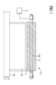
- FIG. 1 a general structure of an electric machine 10 is shown.
- the electric machine 10 may be, for example, a motor or a generator.
- the electric machine 10 can be used, for example, as a generator of a wind power machine.
- an axis of rotation R is also an axis of symmetry of the representation.
- the electric machine 10 comprises a first active part 12 in the form of a stator, in which windings of electrical coils are arranged, wherein FIG. 1 only one of the windings 14 is shown.
- the windings 14 are alternately energized by a three-phase current source C, whereby in the interior of the stator, a magnetic rotating field in an air gap L of the electric machine 10 is formed.
- the three-phase current source C can be, for example, an inverter or a fixed-frequency electrical supply network.
- first active part 12 there is a second active part 16 in the form of a rotor, which is non-rotatably connected to a shaft 18.
- the shaft 18 is rotatable about the rotation axis R and supported in the first active part 12.
- the invention will be described with reference to an internal rotor electric machine 10.
- the electric machine 10 can also be an external rotor.
- the stator is arranged inside the rotor.
- it can also be a linear motor.
- FIG. 2 an iron package with iron packet segments 20 is shown.
- the iron package In large size electric motors or generators, the iron package is segmented due to the workability and portability. Since the electric machine 10 is rotatable, the iron packet segments 20 are bent in a circle about the rotation axis R. If the electric machine 10 were a linear machine, the iron packet segments 20 would be straight.
- the iron packet segments 20 are as FIG. 2 can be seen, preferably the same structure.
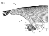
- the first active part segment 22 is part of the first active part 12, which is composed of at least one first active part segment 22 and at least one second active part segment (in FIG FIG. 3 not shown).
- the first active part 12 may in particular be a stator.
- the first active part segment 22 comprises, as in FIG. 2 shown, an iron core segment 20 having first grooves 30.
- a first winding section 26 is arranged or inserted.
- a first connecting element 34 projects out of one of the first grooves 30 on a first winding head side 50.
- the first connection element 34 of the first winding section 26 projects as well as the winding overhang of the winding section 26 on a winding side 50 from one of the first grooves 30 of the iron packet segment 20 out.
- the first active part segment 22 may further, as FIG. 3 it can be seen at a further end opposite the first end 46, a further connection element, which may be formed analogous to the first connection element 34 comprise.
- the first winding section 26 comprises a plurality of windings, which have a plurality of sub-conductors.
- the first winding section 26 has four first windings 36. Each turn comprises three first sub-conductors 38.
- This division of the first winding section 26 can be seen in particular at the first connection element 34. This division, ie the number of turns and the number of sub-conductors per turn, applies analogously to the second winding section (in FIG FIG. 3 not shown).
- the first connecting element 34 is stripped, ie the first windings 36 with their first sub-conductors 38 project individually from the first winding-end side 50.
- a winding part of a single winding of the winding system is arranged in each groove of the first grooves 30 of the first active part segment 22. Another winding part of the winding is located in another groove 30 of the active part segment 22. In each groove 30 of the active part segment 22 is in each case only one winding part of one of several windings of the winding system.
- Such a winding system is also referred to as a single-layer winding.
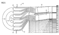
- FIG. 3 is a two-layer winding shown.
- the first winding section 26 is composed of three parallel arranged in individual grooves 30 adjacent conductors.
- the first connection element 34 has three conductors.
- the three conductors are wound successively offset by three grooves 30.
- Each of the three conductors is assigned to a phase.
- a conductor leg of a conductor and a further conductor leg of another conductor is arranged in each of the first grooves 30 of the first active part segment 22.
- the other conductor leg of the one conductor and the other conductor leg of the further conductor are arranged in two other grooves of the first grooves 30 of the first active part segment 22.
- the second active part segment 24 which is preferably identical in construction to the first active part segment 22 is formed.
- the second active part segment 24 such as in FIG. 4 shown, an iron core segment 20 with second grooves 32.
- a second winding section 28 is arranged or inserted.
- a second connecting element 40 protrudes from one of the second grooves 3 on a second winding head side 54.
- the second winding section 28 comprises a plurality of second windings 42 which have a plurality of second sub-conductors 44.
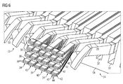
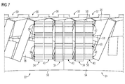
- a section of the first active part 12 with the first active part segment 22 and the second active part segment 24 is shown.
- the first winding section 26 in this case has the first connection element 34, which is divided into three leaders.
- the second winding section 28 has a second connection element 40, which is also divided into three conductors.
- the second connection element 40 and thus each conductor, comprises second windings 42.
- Each winding also has second sub-conductors 44.
- the second connection element 40 also comprises four second windings 42, each having three second partial conductors 44.
- the first end face 48 at the first end 46 of the first active part segment 22 and the second end side 52 at the second end 52 of the second active part segment 24 are arranged adjacent to one another.
- the first connection element 34 is connected to the second connection element 40 in a segment transition region.
- the first connection element 34 and the second connection element 40 perpendicular to the direction of movement of the second active part (in 4 to FIG. 7 not shown) in overlap with each other, so one above the other, arranged.
- the second connection element 40 is arranged above the first connection element 34.
- the respective conductors of the respective connection elements 34, 40 are arranged one above the other.
- a total of two conductors and thus six turns are shown one above the other.
- the first connection element 34 and the second connection element 40 may be arranged parallel to one another in the direction of movement of the second active part.
- the respective conductors of the respective connection elements 34, 40 are arranged alternately next to one another.
- connection elements 34, 40 may be provided.
- connection connection 58 between the first windings 36 and the second windings 42. Therein, one turn of the first turns 36 is connected to one turn of the second turns 42.
- connection connection 58 is shown in the form of a border. Connected in each case is a turn of the first windings 36 with one turn of the second windings 42.
- connection connection 58 may be provided for both embodiments as a detachable or non-detachable connection connection.
- a releasable connection connection 58 for example, a stapling can be carried out according to the principle of the luster terminal.
- a crimp connection or a solder connection may be provided for permanent connections.
- coil rods are used only in the segment transition region instead of complete coils. These can then be integrated directly into the production process and the segment can be completely impregnated. When motor / generator mounting then only the segment connections (electrical connections) must be attached. If this type of connection is additionally chosen in such a way that it can be opened non-destructively, the further consequence is the advantage of much easier segment interchangeability.
Landscapes
- Engineering & Computer Science (AREA)
- Power Engineering (AREA)
- Life Sciences & Earth Sciences (AREA)
- Sustainable Energy (AREA)
- Sustainable Development (AREA)
- Windings For Motors And Generators (AREA)
Priority Applications (2)
| Application Number | Priority Date | Filing Date | Title |
|---|---|---|---|
| EP15164650.2A EP3086442B1 (fr) | 2015-04-22 | 2015-04-22 | Machine électrique doté d'une première partie active et d'une seconde partie active |
| ES15164650T ES2812575T3 (es) | 2015-04-22 | 2015-04-22 | Máquina eléctrica con una primera parte activa y una segunda parte activa |
Applications Claiming Priority (1)
| Application Number | Priority Date | Filing Date | Title |
|---|---|---|---|
| EP15164650.2A EP3086442B1 (fr) | 2015-04-22 | 2015-04-22 | Machine électrique doté d'une première partie active et d'une seconde partie active |
Publications (2)
| Publication Number | Publication Date |
|---|---|
| EP3086442A1 true EP3086442A1 (fr) | 2016-10-26 |
| EP3086442B1 EP3086442B1 (fr) | 2020-05-27 |
Family
ID=52991642
Family Applications (1)
| Application Number | Title | Priority Date | Filing Date |
|---|---|---|---|
| EP15164650.2A Active EP3086442B1 (fr) | 2015-04-22 | 2015-04-22 | Machine électrique doté d'une première partie active et d'une seconde partie active |
Country Status (2)
| Country | Link |
|---|---|
| EP (1) | EP3086442B1 (fr) |
| ES (1) | ES2812575T3 (fr) |
Cited By (1)
| Publication number | Priority date | Publication date | Assignee | Title |
|---|---|---|---|---|
| CN113950786A (zh) * | 2019-06-07 | 2022-01-18 | 西门子股份公司 | 用于旋转电机的定子 |
Citations (6)
| Publication number | Priority date | Publication date | Assignee | Title |
|---|---|---|---|---|
| US6459187B1 (en) * | 2000-01-20 | 2002-10-01 | Mitsubishi Denki Kabushiki Kaisha | Alternator |
| EP1246341A2 (fr) * | 2001-03-28 | 2002-10-02 | Mitsubishi Denki Kabushiki Kaisha | Noyau statorique de machine dynamo-électrique et son procédé de fabrication |
| EP2020731A1 (fr) * | 2006-05-25 | 2009-02-04 | Mitsubishi Electric Corporation | Stator de machine dynamo-électrique |
| EP2211443A1 (fr) * | 2009-01-23 | 2010-07-28 | Siemens Aktiengesellschaft | Fabrication de segments avec des bobines spéciales aux extrémités pour la connexion des segments |
| EP2395632A1 (fr) * | 2010-06-10 | 2011-12-14 | Siemens Aktiengesellschaft | Unité de segment de stator adaptée pour constituer un élément d'un stator en forme d'anneau |
| EP2416471A1 (fr) * | 2009-12-18 | 2012-02-08 | Toyota Jidosha Kabushiki Kaisha | Stator |
-
2015
- 2015-04-22 ES ES15164650T patent/ES2812575T3/es active Active
- 2015-04-22 EP EP15164650.2A patent/EP3086442B1/fr active Active
Patent Citations (6)
| Publication number | Priority date | Publication date | Assignee | Title |
|---|---|---|---|---|
| US6459187B1 (en) * | 2000-01-20 | 2002-10-01 | Mitsubishi Denki Kabushiki Kaisha | Alternator |
| EP1246341A2 (fr) * | 2001-03-28 | 2002-10-02 | Mitsubishi Denki Kabushiki Kaisha | Noyau statorique de machine dynamo-électrique et son procédé de fabrication |
| EP2020731A1 (fr) * | 2006-05-25 | 2009-02-04 | Mitsubishi Electric Corporation | Stator de machine dynamo-électrique |
| EP2211443A1 (fr) * | 2009-01-23 | 2010-07-28 | Siemens Aktiengesellschaft | Fabrication de segments avec des bobines spéciales aux extrémités pour la connexion des segments |
| EP2416471A1 (fr) * | 2009-12-18 | 2012-02-08 | Toyota Jidosha Kabushiki Kaisha | Stator |
| EP2395632A1 (fr) * | 2010-06-10 | 2011-12-14 | Siemens Aktiengesellschaft | Unité de segment de stator adaptée pour constituer un élément d'un stator en forme d'anneau |
Cited By (2)
| Publication number | Priority date | Publication date | Assignee | Title |
|---|---|---|---|---|
| CN113950786A (zh) * | 2019-06-07 | 2022-01-18 | 西门子股份公司 | 用于旋转电机的定子 |
| US12046964B2 (en) | 2019-06-07 | 2024-07-23 | Innomotics Gmbh | Stator for a rotating electrical machine |
Also Published As
| Publication number | Publication date |
|---|---|
| ES2812575T3 (es) | 2021-03-17 |
| EP3086442B1 (fr) | 2020-05-27 |
Similar Documents
| Publication | Publication Date | Title |
|---|---|---|
| EP1811634B1 (fr) | Réfrigérateur doté d'un dispositif de production de glace | |
| DE112014005444B4 (de) | Anker für eine elektrische Maschine | |
| WO2007085527A1 (fr) | Machine électrique comprenant un système d'enroulement à trois faisceaux | |
| DE102014105428A1 (de) | Wicklungslayout für einen Stator mit Stabwicklungen mit Windungen, die eine verlängerte Spulenweite und eine verkürzte Spulenweite aufweisen | |
| EP3347973B1 (fr) | Stator de machine electrique et machine electrique et procede de fabrication | |
| DE102005018777A1 (de) | Statorspule mit konzentrierter Wicklung für eine rotierende elektrische Maschine | |
| DE102005019271A1 (de) | Statorspule mit konzentrierter Wicklung für eine rotierende elektrische Maschine | |
| DE102011120985A1 (de) | Elektrische Maschine mit einem Stator und Wickel- und Kontaktierungsverfahren für eine elektrische Maschine | |
| DE102012214523B4 (de) | Ständer oder Ständersegment einer dynamoelektrischen Maschine mit optimiertem Wickelkopf, dynamoelektrische Maschine und Rohrmühle oder Windkraftgenerator | |
| DE102018221570A1 (de) | Halteelement eines Rotors eines Elektromotors zum Halten von Wicklungen | |
| EP3547501A1 (fr) | Segment de stator | |
| DE102005018600A1 (de) | Statorspule mit konzentrierter Wicklung für eine rotierende elektrische Maschine | |
| EP3183799B1 (fr) | Pièce active d'une machine électrique | |
| EP3086442B1 (fr) | Machine électrique doté d'une première partie active et d'une seconde partie active | |
| DE102017216631A1 (de) | Elektrische Maschine | |
| DE102006048967A1 (de) | Stator für eine elektrische Maschine | |
| DE102021125488A1 (de) | Stator einer elektrischen Rotationsmaschine sowie elektrische Rotationsmaschine | |
| EP2882080B1 (fr) | Machine rotative dynamoélectrique | |
| EP3863163B1 (fr) | Segment de stator | |
| WO2004015844A1 (fr) | Machine electrique | |
| EP3079242A1 (fr) | Procédé de fabrication de bobine autour d`un pole salisant pour une machine synchrone | |
| DE102022204816A1 (de) | Leistungserzeugende Komponente einer elektrischen Maschine und Wellenwicklung | |
| DE102023205277A1 (de) | Verteilte Wicklung für eine elektrische Maschine in Sternschaltung | |
| DE102023205305A1 (de) | Verteilte Wicklung für eine elektrische Maschine | |
| DE102015226106A1 (de) | Elektrische Maschine sowie Motorsystem mit einer elektrischen Maschine |
Legal Events
| Date | Code | Title | Description |
|---|---|---|---|
| PUAI | Public reference made under article 153(3) epc to a published international application that has entered the european phase |
Free format text: ORIGINAL CODE: 0009012 |
|
| AK | Designated contracting states |
Kind code of ref document: A1 Designated state(s): AL AT BE BG CH CY CZ DE DK EE ES FI FR GB GR HR HU IE IS IT LI LT LU LV MC MK MT NL NO PL PT RO RS SE SI SK SM TR |
|
| AX | Request for extension of the european patent |
Extension state: BA ME |
|
| 17P | Request for examination filed |
Effective date: 20170426 |
|
| RBV | Designated contracting states (corrected) |
Designated state(s): AL AT BE BG CH CY CZ DE DK EE ES FI FR GB GR HR HU IE IS IT LI LT LU LV MC MK MT NL NO PL PT RO RS SE SI SK SM TR |
|
| STAA | Information on the status of an ep patent application or granted ep patent |
Free format text: STATUS: REQUEST FOR EXAMINATION WAS MADE |
|
| RAP1 | Party data changed (applicant data changed or rights of an application transferred) |
Owner name: SIEMENS AKTIENGESELLSCHAFT |
|
| STAA | Information on the status of an ep patent application or granted ep patent |
Free format text: STATUS: EXAMINATION IS IN PROGRESS |
|
| 17Q | First examination report despatched |
Effective date: 20190502 |
|
| GRAP | Despatch of communication of intention to grant a patent |
Free format text: ORIGINAL CODE: EPIDOSNIGR1 |
|
| STAA | Information on the status of an ep patent application or granted ep patent |
Free format text: STATUS: GRANT OF PATENT IS INTENDED |
|
| INTG | Intention to grant announced |
Effective date: 20200117 |
|
| GRAS | Grant fee paid |
Free format text: ORIGINAL CODE: EPIDOSNIGR3 |
|
| GRAA | (expected) grant |
Free format text: ORIGINAL CODE: 0009210 |
|
| STAA | Information on the status of an ep patent application or granted ep patent |
Free format text: STATUS: THE PATENT HAS BEEN GRANTED |
|
| AK | Designated contracting states |
Kind code of ref document: B1 Designated state(s): AL AT BE BG CH CY CZ DE DK EE ES FI FR GB GR HR HU IE IS IT LI LT LU LV MC MK MT NL NO PL PT RO RS SE SI SK SM TR |
|
| REG | Reference to a national code |
Ref country code: GB Ref legal event code: FG4D Free format text: NOT ENGLISH |
|
| REG | Reference to a national code |
Ref country code: CH Ref legal event code: EP |
|
| REG | Reference to a national code |
Ref country code: DE Ref legal event code: R096 Ref document number: 502015012643 Country of ref document: DE |
|
| REG | Reference to a national code |
Ref country code: AT Ref legal event code: REF Ref document number: 1275582 Country of ref document: AT Kind code of ref document: T Effective date: 20200615 |
|
| REG | Reference to a national code |
Ref country code: LT Ref legal event code: MG4D |
|
| PG25 | Lapsed in a contracting state [announced via postgrant information from national office to epo] |
Ref country code: NO Free format text: LAPSE BECAUSE OF FAILURE TO SUBMIT A TRANSLATION OF THE DESCRIPTION OR TO PAY THE FEE WITHIN THE PRESCRIBED TIME-LIMIT Effective date: 20200827 Ref country code: GR Free format text: LAPSE BECAUSE OF FAILURE TO SUBMIT A TRANSLATION OF THE DESCRIPTION OR TO PAY THE FEE WITHIN THE PRESCRIBED TIME-LIMIT Effective date: 20200828 Ref country code: FI Free format text: LAPSE BECAUSE OF FAILURE TO SUBMIT A TRANSLATION OF THE DESCRIPTION OR TO PAY THE FEE WITHIN THE PRESCRIBED TIME-LIMIT Effective date: 20200527 Ref country code: LT Free format text: LAPSE BECAUSE OF FAILURE TO SUBMIT A TRANSLATION OF THE DESCRIPTION OR TO PAY THE FEE WITHIN THE PRESCRIBED TIME-LIMIT Effective date: 20200527 Ref country code: PT Free format text: LAPSE BECAUSE OF FAILURE TO SUBMIT A TRANSLATION OF THE DESCRIPTION OR TO PAY THE FEE WITHIN THE PRESCRIBED TIME-LIMIT Effective date: 20200928 Ref country code: SE Free format text: LAPSE BECAUSE OF FAILURE TO SUBMIT A TRANSLATION OF THE DESCRIPTION OR TO PAY THE FEE WITHIN THE PRESCRIBED TIME-LIMIT Effective date: 20200527 Ref country code: IS Free format text: LAPSE BECAUSE OF FAILURE TO SUBMIT A TRANSLATION OF THE DESCRIPTION OR TO PAY THE FEE WITHIN THE PRESCRIBED TIME-LIMIT Effective date: 20200927 |
|
| REG | Reference to a national code |
Ref country code: NL Ref legal event code: MP Effective date: 20200527 |
|
| PG25 | Lapsed in a contracting state [announced via postgrant information from national office to epo] |
Ref country code: HR Free format text: LAPSE BECAUSE OF FAILURE TO SUBMIT A TRANSLATION OF THE DESCRIPTION OR TO PAY THE FEE WITHIN THE PRESCRIBED TIME-LIMIT Effective date: 20200527 Ref country code: RS Free format text: LAPSE BECAUSE OF FAILURE TO SUBMIT A TRANSLATION OF THE DESCRIPTION OR TO PAY THE FEE WITHIN THE PRESCRIBED TIME-LIMIT Effective date: 20200527 Ref country code: BG Free format text: LAPSE BECAUSE OF FAILURE TO SUBMIT A TRANSLATION OF THE DESCRIPTION OR TO PAY THE FEE WITHIN THE PRESCRIBED TIME-LIMIT Effective date: 20200827 Ref country code: LV Free format text: LAPSE BECAUSE OF FAILURE TO SUBMIT A TRANSLATION OF THE DESCRIPTION OR TO PAY THE FEE WITHIN THE PRESCRIBED TIME-LIMIT Effective date: 20200527 |
|
| PG25 | Lapsed in a contracting state [announced via postgrant information from national office to epo] |
Ref country code: AL Free format text: LAPSE BECAUSE OF FAILURE TO SUBMIT A TRANSLATION OF THE DESCRIPTION OR TO PAY THE FEE WITHIN THE PRESCRIBED TIME-LIMIT Effective date: 20200527 Ref country code: NL Free format text: LAPSE BECAUSE OF FAILURE TO SUBMIT A TRANSLATION OF THE DESCRIPTION OR TO PAY THE FEE WITHIN THE PRESCRIBED TIME-LIMIT Effective date: 20200527 |
|
| PG25 | Lapsed in a contracting state [announced via postgrant information from national office to epo] |
Ref country code: EE Free format text: LAPSE BECAUSE OF FAILURE TO SUBMIT A TRANSLATION OF THE DESCRIPTION OR TO PAY THE FEE WITHIN THE PRESCRIBED TIME-LIMIT Effective date: 20200527 Ref country code: IT Free format text: LAPSE BECAUSE OF FAILURE TO SUBMIT A TRANSLATION OF THE DESCRIPTION OR TO PAY THE FEE WITHIN THE PRESCRIBED TIME-LIMIT Effective date: 20200527 Ref country code: SM Free format text: LAPSE BECAUSE OF FAILURE TO SUBMIT A TRANSLATION OF THE DESCRIPTION OR TO PAY THE FEE WITHIN THE PRESCRIBED TIME-LIMIT Effective date: 20200527 Ref country code: RO Free format text: LAPSE BECAUSE OF FAILURE TO SUBMIT A TRANSLATION OF THE DESCRIPTION OR TO PAY THE FEE WITHIN THE PRESCRIBED TIME-LIMIT Effective date: 20200527 Ref country code: CZ Free format text: LAPSE BECAUSE OF FAILURE TO SUBMIT A TRANSLATION OF THE DESCRIPTION OR TO PAY THE FEE WITHIN THE PRESCRIBED TIME-LIMIT Effective date: 20200527 Ref country code: DK Free format text: LAPSE BECAUSE OF FAILURE TO SUBMIT A TRANSLATION OF THE DESCRIPTION OR TO PAY THE FEE WITHIN THE PRESCRIBED TIME-LIMIT Effective date: 20200527 |
|
| PG25 | Lapsed in a contracting state [announced via postgrant information from national office to epo] |
Ref country code: PL Free format text: LAPSE BECAUSE OF FAILURE TO SUBMIT A TRANSLATION OF THE DESCRIPTION OR TO PAY THE FEE WITHIN THE PRESCRIBED TIME-LIMIT Effective date: 20200527 Ref country code: SK Free format text: LAPSE BECAUSE OF FAILURE TO SUBMIT A TRANSLATION OF THE DESCRIPTION OR TO PAY THE FEE WITHIN THE PRESCRIBED TIME-LIMIT Effective date: 20200527 |
|
| REG | Reference to a national code |
Ref country code: DE Ref legal event code: R097 Ref document number: 502015012643 Country of ref document: DE |
|
| REG | Reference to a national code |
Ref country code: CH Ref legal event code: NV Representative=s name: SIEMENS SCHWEIZ AG, CH |
|
| REG | Reference to a national code |
Ref country code: ES Ref legal event code: FG2A Ref document number: 2812575 Country of ref document: ES Kind code of ref document: T3 Effective date: 20210317 |
|
| PLBE | No opposition filed within time limit |
Free format text: ORIGINAL CODE: 0009261 |
|
| STAA | Information on the status of an ep patent application or granted ep patent |
Free format text: STATUS: NO OPPOSITION FILED WITHIN TIME LIMIT |
|
| 26N | No opposition filed |
Effective date: 20210302 |
|
| PG25 | Lapsed in a contracting state [announced via postgrant information from national office to epo] |
Ref country code: SI Free format text: LAPSE BECAUSE OF FAILURE TO SUBMIT A TRANSLATION OF THE DESCRIPTION OR TO PAY THE FEE WITHIN THE PRESCRIBED TIME-LIMIT Effective date: 20200527 |
|
| PGFP | Annual fee paid to national office [announced via postgrant information from national office to epo] |
Ref country code: GB Payment date: 20210504 Year of fee payment: 7 |
|
| PG25 | Lapsed in a contracting state [announced via postgrant information from national office to epo] |
Ref country code: MC Free format text: LAPSE BECAUSE OF FAILURE TO SUBMIT A TRANSLATION OF THE DESCRIPTION OR TO PAY THE FEE WITHIN THE PRESCRIBED TIME-LIMIT Effective date: 20200527 |
|
| PG25 | Lapsed in a contracting state [announced via postgrant information from national office to epo] |
Ref country code: LU Free format text: LAPSE BECAUSE OF NON-PAYMENT OF DUE FEES Effective date: 20210422 |
|
| REG | Reference to a national code |
Ref country code: BE Ref legal event code: MM Effective date: 20210430 |
|
| PG25 | Lapsed in a contracting state [announced via postgrant information from national office to epo] |
Ref country code: FR Free format text: LAPSE BECAUSE OF NON-PAYMENT OF DUE FEES Effective date: 20210430 Ref country code: LI Free format text: LAPSE BECAUSE OF NON-PAYMENT OF DUE FEES Effective date: 20210430 Ref country code: CH Free format text: LAPSE BECAUSE OF NON-PAYMENT OF DUE FEES Effective date: 20210430 |
|
| PG25 | Lapsed in a contracting state [announced via postgrant information from national office to epo] |
Ref country code: IE Free format text: LAPSE BECAUSE OF NON-PAYMENT OF DUE FEES Effective date: 20210422 |
|
| REG | Reference to a national code |
Ref country code: AT Ref legal event code: MM01 Ref document number: 1275582 Country of ref document: AT Kind code of ref document: T Effective date: 20210422 |
|
| PG25 | Lapsed in a contracting state [announced via postgrant information from national office to epo] |
Ref country code: BE Free format text: LAPSE BECAUSE OF NON-PAYMENT OF DUE FEES Effective date: 20210430 |
|
| PG25 | Lapsed in a contracting state [announced via postgrant information from national office to epo] |
Ref country code: AT Free format text: LAPSE BECAUSE OF NON-PAYMENT OF DUE FEES Effective date: 20210422 |
|
| GBPC | Gb: european patent ceased through non-payment of renewal fee |
Effective date: 20220422 |
|
| PG25 | Lapsed in a contracting state [announced via postgrant information from national office to epo] |
Ref country code: GB Free format text: LAPSE BECAUSE OF NON-PAYMENT OF DUE FEES Effective date: 20220422 |
|
| PG25 | Lapsed in a contracting state [announced via postgrant information from national office to epo] |
Ref country code: HU Free format text: LAPSE BECAUSE OF FAILURE TO SUBMIT A TRANSLATION OF THE DESCRIPTION OR TO PAY THE FEE WITHIN THE PRESCRIBED TIME-LIMIT; INVALID AB INITIO Effective date: 20150422 |
|
| P01 | Opt-out of the competence of the unified patent court (upc) registered |
Effective date: 20230510 |
|
| PG25 | Lapsed in a contracting state [announced via postgrant information from national office to epo] |
Ref country code: CY Free format text: LAPSE BECAUSE OF FAILURE TO SUBMIT A TRANSLATION OF THE DESCRIPTION OR TO PAY THE FEE WITHIN THE PRESCRIBED TIME-LIMIT Effective date: 20200527 |
|
| PG25 | Lapsed in a contracting state [announced via postgrant information from national office to epo] |
Ref country code: MK Free format text: LAPSE BECAUSE OF FAILURE TO SUBMIT A TRANSLATION OF THE DESCRIPTION OR TO PAY THE FEE WITHIN THE PRESCRIBED TIME-LIMIT Effective date: 20200527 |
|
| PG25 | Lapsed in a contracting state [announced via postgrant information from national office to epo] |
Ref country code: TR Free format text: LAPSE BECAUSE OF FAILURE TO SUBMIT A TRANSLATION OF THE DESCRIPTION OR TO PAY THE FEE WITHIN THE PRESCRIBED TIME-LIMIT Effective date: 20200527 |
|
| PG25 | Lapsed in a contracting state [announced via postgrant information from national office to epo] |
Ref country code: MT Free format text: LAPSE BECAUSE OF FAILURE TO SUBMIT A TRANSLATION OF THE DESCRIPTION OR TO PAY THE FEE WITHIN THE PRESCRIBED TIME-LIMIT Effective date: 20200527 |
|
| REG | Reference to a national code |
Ref country code: ES Ref legal event code: PC2A Owner name: INNOMOTICS GMBH Effective date: 20241115 |
|
| PGFP | Annual fee paid to national office [announced via postgrant information from national office to epo] |
Ref country code: DE Payment date: 20250429 Year of fee payment: 11 |
|
| PGFP | Annual fee paid to national office [announced via postgrant information from national office to epo] |
Ref country code: ES Payment date: 20250513 Year of fee payment: 11 |
|
| REG | Reference to a national code |
Ref country code: DE Ref legal event code: R081 Ref document number: 502015012643 Country of ref document: DE Owner name: INNOMOTICS GMBH, DE Free format text: FORMER OWNER: SIEMENS AKTIENGESELLSCHAFT, 80333 MUENCHEN, DE |