EP3086460B1 - Triboelektrischer generator - Google Patents
Triboelektrischer generator Download PDFInfo
- Publication number
- EP3086460B1 EP3086460B1 EP16163889.5A EP16163889A EP3086460B1 EP 3086460 B1 EP3086460 B1 EP 3086460B1 EP 16163889 A EP16163889 A EP 16163889A EP 3086460 B1 EP3086460 B1 EP 3086460B1
- Authority
- EP
- European Patent Office
- Prior art keywords
- electrode
- energy generation
- generation layer
- triboelectric generator
- substrate
- Prior art date
- Legal status (The legal status is an assumption and is not a legal conclusion. Google has not performed a legal analysis and makes no representation as to the accuracy of the status listed.)
- Active
Links
Images








Classifications
-
- H—ELECTRICITY
- H02—GENERATION; CONVERSION OR DISTRIBUTION OF ELECTRIC POWER
- H02N—ELECTRIC MACHINES NOT OTHERWISE PROVIDED FOR
- H02N1/00—Electrostatic generators or motors using a solid moving electrostatic charge carrier
- H02N1/04—Friction generators
Definitions
- Example embodiments relate to a triboelectric generator, and more particularly, to a triboelectric generator using a one-dimensional nanomaterial or a two-dimensional material.
- Energy harvesting devices are new eco-friendly energy generating devices that may extract energy by converting mechanical energy generated from wind, vibrations, or movements of a person with respect to a surrounding environment to electric energy.
- Example embodiments relate to a triboelectric generator using a two-dimensional material.
- a triboelectric generator includes first and second electrodes provided to face each other, and a first energy generation layer provided on the first electrode and generating electric energy through contact with other material, the first energy generation layer consisting of a two-dimensional (2D) material having a crystal structure of a 2D shape.
- the two-dimensional material may include at least one of hexagonal-boron nitride (h-BN) and transition metal dichalcogenide (TMD).
- the TMD may include one metal element from Mo, W, Nb, V, Ta, Ti, Zr, Hf, Tc, Re, Cu, Ga, In, Sn, Ge, and Pb and one chalcogen element from S, Se, and Te.
- the 2D material may have a single layer or a multilayer structure.
- the 2D material may have a thickness of about 0.3 nm to about 1000 nm.
- the 2D material may be doped or undoped.
- the triboelectric generator may further include a spacer provided between the first electrode and the second electrode.
- the first energy layer may generate electric energy through contact with the second electrode.
- the triboelectric generator may further include at least one of a first substrate on which the first electrode and the first energy generation layer are provided and a second substrate on which the second electrode is provided.
- the first energy generation layer may generate electric energy through contact with the second electrode or the second substrate.
- At least one of the first and second substrates may be stretchable. At least one of the first and second substrates may include at least one of polydimethylsiloxane (PDMS), polyimide (PI), Teflon, urethane, and nylon. At least one of the first and second substrates may have an elongation percentage of about 200% or low.
- PDMS polydimethylsiloxane
- PI polyimide
- Teflon Teflon
- urethane urethane
- nylon nylon
- At least one of the first and second substrates may have an elongation percentage of about 200% or low.
- At least one of the first and second substrates may have a surface having a shape of a wavy pattern.
- the first electrode and the first energy generation layer may have a shape corresponding to a surface of the first substrate and the second electrode may have a shape corresponding to a surface of the second substrate.
- At least one of the first and second electrodes may include at least one of carbon nanotube (CNT), graphene, Ag nanowire, metal, and metal mesh.
- CNT carbon nanotube
- the triboelectric generator may further include a second energy generation layer provided on the second electrode and generating electric energy through contact with the first energy generation layer.
- the triboelectric generator may further include at least one of a first substrate on which the first electrode and the first energy generation layer are provided, and a second substrate on which the second electrode and the second energy generation layer are provided. At least one of the first and second substrates may be stretchable.
- a triboelectric generator includes first and second electrodes provided to face each other and having stretchability, and a first energy generation layer provided on the first electrode and generating electric energy through contact with another material or other materials.
- the first energy generation layer consists of a two-dimensional (2D) material having a crystal structure of a 2D shape.
- the first energy generation layer may generate electric energy through contact with the second electrode.
- the triboelectric generator may further include at least one of a first substrate that is stretchable, on which the first electrode and the first energy generation layer are provided, and a second substrate that is stretchable, on which the second electrode is provided.
- the first energy generation layer may generate electric energy through contact with the second electrode or the second substrate.
- At least one of the first and second substrates may have a surface having a shape of a wavy pattern.
- the first electrode and the first energy generation layer may have a shape corresponding to a surface of the first substrate, and the second electrode has a shape corresponding to a surface of the second substrate.
- the triboelectric generator may further include a second energy generation layer provided on the second electrode and generating electric energy through contact with the first energy generation layer.
- the triboelectric generator may further include at least one of a first substrate that is stretchable, on which the first electrode and the first energy generation layer are provided, and a second substrate that is stretchable, on which the second electrode and the second energy generation layer are provided.
- a triboelectric generator includes a plurality of energy generation units that are stacked on top of each other, wherein each of, or one or more of, the energy generation units includes first and second electrodes provided to face each other, and a first energy generation layer provided on the first electrode and generating electric energy through contact with other material, the first energy generation layer consisting of a 2D material having a crystal structure of a 2D shape.
- the 2D material may include at least one of graphene, h-BN, and TMD.
- the triboelectric generator may further include a second energy generation layer provided on the second electrode and generating electric energy through contact with the first energy generation layer.
- the energy generation units may be serially connected to one another.
- a triboelectric generator includes a plurality of energy generation units that are stacked on top of each other, wherein each of, or one or more of, the energy generation units includes first and second electrodes provided to face each other and having stretchability, and a first energy generation layer provided on the first electrode and generating electric energy through contact with other material.
- the first energy generation layer consists of a 2D material having a crystal structure of a 2D shape.
- the triboelectric generator may further include a second energy generation layer provided on the second electrode and generating electric energy through contact with the first energy generation layer.
- tubular elements of the embodiments may be cylindrical, other tubular cross-sectional forms are contemplated, such as square, rectangular, oval, triangular and others.
- FIG. 1 is a cross-sectional view of a triboelectric generator according to an example embodiment.
- the triboelectric generator may include first and second electrodes 111 and 121 separated from and facing each other, and an energy generation layer 130 provided on the first electrode 111.
- the energy generation layer 130 is provided on an upper surface of the first electrode 111 facing the second electrode 121.
- the first and second electrodes 111 and 121 may include a conductive material.
- the first and second electrodes 111 and 121 may have rigid characteristics.
- one or both of the first and second electrodes 111 and 121 may be flexible and stretchable.
- a flexible and stretchable electrode may include, for example, one or two or more combinations of carbon nanotube (CNT), graphene, Ag nanowire, metal, and metal mesh, but the example embodiments are not limited thereto.
- the flexible and stretchable electrode may include fabric woven with conductive fibers.
- the flexible and stretchable electrode may have, for example, an elongation percentage of about 200% or lower.
- the example embodiments are not limited thereto.
- the energy generation layer 130 is provided on the upper surface of the first electrode 111 and may generate electric energy through contact with the second electrode 121.
- the energy generation layer 130 may include a material having charging characteristics that are different from the second electrode 121.
- the energy generation layer 130 consists of a two-dimensional (2D) material having a crystal structure of a 2D shape.
- the 2D material may include, for example, hexagonal-boron nitride (h-BN) and/or transition metal dichalcogenide (TMD).
- the 2D material may have a monolayer structure or a multilayer structure.
- the number of layers of the 2D material may be about 1 ⁇ 300, but the example embodiments are not limited thereto.
- Each layer forming the 2D material may have a thickness of an atomic level.
- the thickness of the 2D material may be, for example, about 0.3 nm ⁇ about 1000 nm, but the example embodiments are not limited thereto.
- the layers of the 2D material having a multilayer structure may be combined by the van der Waals force.
- the h-BN is an insulating material having a crystal structure of a 2D shape.
- the h-BN may exhibit thermal stability, superior mechanical strength, high thermal conductivity, and a low dielectric constant.
- the TMD is a semiconductor having a crystal structure of a 2D shape.
- the TMD may include one of transition metals such as Mo, W, Nb, V, Ta, Ti, Zr, Hf, Tc, and Re and one of chalcogen elements such as S, Se, and Te.
- the TMD may be expressed by, for example, MX 2 , where M denotes a transition metal and X denotes a chalcogen element.
- the M may be Mo, W, Nb, V, Ta, Ti, Zr, Hf, Tc, or Re
- the X may be S, Se, or Te.
- the TDM may include, for example, MoS 2 , MoSe 2 , MoTe 2 , WS 2 , WSe 2 , WTe 2 , ZrS 2 , ZrSe 2 , HfS 2 , HfSe 2 , NbSe 2 , or ReSe 2
- the TMD may not be expressed by MX 2 .
- the TMD may include CuS that is a compound of Cu that is a transition metal and S that is a chalcogen element.
- the TMD may be a chalcogenide material including a non-transition metal.
- the non-transition metal may include, for example, Ga, In, Sn, Ge, or Pb.
- the TMD may include a compound of a non-transition metal such as Ga, In, Sn, Ge, or Pb and a chalcogen element such as S, Se, or Te.
- the TMD may include SnSe 2 , GaS, GaSe, GaTe, GeSe, In 2 Se 3 , or InSnS 2 .
- the TMD may include one metal element of Mo, W, Nb, V, Ta, Ti, Zr, Hf, Tc, Re, Cu, Ga, In, Sn, Ge, and Pb and one chalcogen element of S, Se, and Te.
- the above-described materials are mere examples and other materials may be used as a TMD material.
- the energy generation layer 130 consists of a 2D material.
- the 2D material may include, for example, graphene, h-BN, and/or TMD.
- the graphene is a conductive material obtained as carbon atoms are bonded in a hexagonal 2D shape.
- the 2D material forming the energy generation layer 130 may be doped with a p-type dopant or an n-type dopant.
- the p-type dopant and the n-type dopant may be, for example, a p-type dopant and an n-type dopant used for graphene or CNT.
- the p-type dopant or the n-type dopant may be doped in an ion implantation or chemical doping method.
- a source of the p-type dopant may include, for example, ionic liquid such as NO 2 BF 4 , NOBF 4 , or NO 2 SbF 6 , an acidic compound such as HCI, H 2 PO 4 , CH 3 COOH, H 2 SO 4 , or HNO 3 , and an organic compound such as dichlorodicyanoquinone (DDQ), oxone, dimyristoylphosphatidylinositol (DMPI), or trifluoromethanesulfoneimide.
- DDQ dichlorodicyanoquinone
- DMPI dimyristoylphosphatidylinositol
- trifluoromethanesulfoneimide trifluoromethanesulfoneimide
- a source of the p-type dopant may include HPtCl 4 , AuCl 3 , HAuCl 4 , silver trifluoromethanesulfonate (AgOTf), AgNO 3 , H 2 PdCl 6 , Pd(OAc) 2 , or Cu(CN) 2 .
- a source of the n-type dopant may include, for example, a reduction product of a substituted or unsubstituted nicotinamide, a reduction product of a compound which is chemically bound to a substituted or unsubstituted nicotinamide, and a compound comprising at least two pyridinium moieties in which a nitrogen atom of at least one of the pyridinium moieties is reduced.
- the source of the n-type dopant may include nicotinamide mononucleotide-H (NMNH), nicotinamide adenine dinucleotide-H (NADH), nicotinamide adenine dinucleotide phosphate-H (NADPH), or viologen.
- the source of the n-type dopant may include a polymer such as polyethylenimine (PEI).
- the n-type dopant may include alkali metal such as K or Li.
- the above-described p-type dopant materials and n-type dopant materials are examples and other various materials may be used as dopants.
- the energy generation layer 130 may have flexibility and stretchability corresponding to, similar to or the same as the flexibility and stretchability of the first electrode 111.
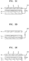
- FIGS. 2A to 2E illustrate an operation of the triboelectric generator illustrated in FIG. 1 to generate electric energy by pressing or bending.
- the energy generation layer 130 is provided on the upper surface of the first electrode 111, and the energy generation layer 130 and the second electrode 121 are separated by a desired, or alternatively predetermined distance from each other.
- the first and second electrodes 111 and 121 are connected to a measurement circuit 170 for measuring generated electric energy.
- an external pressure applied to the second electrode 121 makes the energy generation layer 130 provided on the first electrode 111 and the second electrode 121 contact each other. In the process, an upper surface of the energy generation layer 130 and a lower surface of the second electrode 121 contacting each other are charged with electric charges having desired or alternatively predetermined polarities by friction charging.
- electric energy is generated by a process during which the second electrode 121 in contact with the energy generation layer 130 is separated from the energy generation layer 130.
- the generated electric energy may be obtained through the first and second electrodes 111 and 121.
- a further pressure applied to the second electrode 121 moves the second electrode 121, as illustrated in FIG. 2E .
- electric energy is generated during the process of the second electrode 121 being close to the energy generation layer 130.
- the generated electric energy may be obtained through the first and second electrodes 111 and 121.
- a current generated during the process in which the second electrode 121 and the energy generation layer 130 are close to each other or spaced apart from each other may flow in opposite directions.
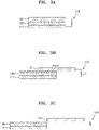
- FIGS. 3A to 3D illustrate an operation of the triboelectric generator illustrated in FIG. 1 to generate electric energy by sliding.
- the energy generation layer 130 and the second electrode 121 when the energy generation layer 130 and the second electrode 121 are in contact with each other, the upper surface of the energy generation layer 130 and the lower surface of the second electrode 121 contacting each other are charged with electric charges having desired or alternatively predetermined polarities by friction charging.
- the second electrode 121 in which the energy generation layer 130 and the second electrode 121 are in contact with each other, the second electrode 121 is slid in a direction away from the energy generation layer 130, that is, a direction in which an area of a contact surface between the second electrode 121 and the energy generation layer 130 decreases. As such, during the sliding process in which the second electrode 121 is moved away from the energy generation layer 130, electric energy is generated and the generated electric energy may be obtained through the first and second electrodes 111 and 121
- the second electrode 121 when the second electrode 121 is away from the energy generation layer 130, as illustrated in FIG. 3D , the second electrode 121 is slid back toward the energy generation layer 130, that is, a direction in which an area of the contact surface between the second electrode 121 and the energy generation layer 130 increases. As such, during the sliding process in which the second electrode 121 is moved closer to the energy generation layer 130, electric energy is generated, and the generated electric energy may be obtained through the first and second electrodes 111 and 121. As such, a current generated during the sliding process may flow in opposite directions ( FIGS. 3B and 3D ).
- FIG. 4 is a cross-sectional view of a triboelectric generator according to another example embodiment.
- one or more spacers 150 may be provided between the energy generation layer 130 and the second electrode 121.
- the one or more spacers 150 may maintain a desired or alternatively predetermined interval between the energy generation layer 130 and the second electrode 121 in a state in which no external mechanical energy is applied to the triboelectric generator.
- FIG. 5 is a cross-sectional view of a triboelectric generator according to another example embodiment.
- the triboelectric generator may include first and second substrates 110 and 120 separated from each other, the first and second electrodes 111 and 121 respectively provided on the first and second substrates 110 and 120, and the energy generation layer 130 provided on the first electrode 111.
- the first and second substrates 110 and 120 may be formed of or include a rigid material, for example, a glass substrate or a silicon substrate. Alternatively, one or both of the first and second substrates 110 and 120 may be flexible and stretchable substrates.
- the flexible and stretchable substrates may include, for example, one or two or more combinations of polydimethylsiloxane (PDMS), polyimide (PI), Teflon, urethane, and nylon. However, the example embodiments are not limited thereto.
- the flexible and stretchable substrates may include fabric woven with fibers.
- the flexible and stretchable substrates may have an elongation percentage of about 200% or low, but the example embodiments are not limited thereto.
- the first electrode 111 is provided on an upper surface of the first substrate 110, and the second electrode 121 is provided on a lower surface of the second substrate 120.
- One or both of the first and second electrodes 111 and 121 may be flexible and stretchable electrodes corresponding to the first and second substrates 110 and 120.
- the energy generation layer 130 that generates electric energy through friction with the second electrode 121 is provided on the upper surface of the first electrode 111.
- the energy generation layer 130 generates electric energy through contact with the second electrode 121.
- the energy generation layer 130 consists of a 2D material including h-BN and/or TMD.
- the energy generation layer 130 consists of a 2D material.
- the 2D material may include graphene, h-BN, and/or TMD.
- FIG. 6 is a cross-sectional view of a triboelectric generator according to another example embodiment.
- the triboelectric generator may include first and second substrates 110' and 120 separated from each other, first and second electrode 111' and 121 respectively provided on the first and second substrates 110' and 120, the energy generation layer 130' being provided on the first electrode 111'.
- the first substrate 110' may be a flexible and stretchable substrate.
- the first substrate 110' may have, for example, an elongation percentage of about 200% or lower, but the example embodiment is not limited thereto.
- An upper surface of the first substrate 110' may have a shape of a wavy pattern.
- the first electrode 111' and the energy generation layer 130' are sequentially provided on the upper surface of the first substrate 110'. Accordingly, the first electrode 111' and the energy generation layer 130' may have a wavy pattern substantially corresponding to the upper surface of the first substrate 110'.
- the first electrode 111' and the energy generation layer 130' may have flexibility and stretchability like the first substrate 110'.
- the first electrode 111' may include, for example, one or two or more combinations of CNT, graphene, Ag nanowire, metal, and metal mesh, but the example embodiment is not limited thereto.
- the energy generation layer 130' generates electric energy through friction with the second electrode 121.
- the energy generation layer 130' consists of a 2D material including h-BN and/or TMD.
- Both of the first and second substrates 110' and 120 may be flexible and stretchable substrates.
- the first electrode 111' and the energy generation layer 130' may have flexibility and stretchability corresponding to, similar to or the same as the flexibility and stretchability of the first substrate 110'.
- the second electrode 121 may have flexibility and stretchability corresponding to, similar to or the same as the flexibility and stretchability of the second substrate 120.
- the energy generation layer 130' consists of a 2D material.
- the 2D material may include, for example, graphene, h-BN, and/or TMD.
- a method of forming the first electrode 111' and the energy generation layer 130' having a shape of a wavy pattern on the first substrate 110' is described as follows. First, the first substrate 110' having stretchability is prepared and stretched. Next, the first electrode 111' and the energy generation layer 130' are sequentially formed on the upper surface of the first substrate 110' in a stretched state. Next, when the first substrate 110' that is stretched is contracted to an original state, the upper surface of the first substrate 110' may have a shape of a wavy pattern due to contraction. Accordingly, the first electrode 111' and the energy generation layer 130' may have a shape of a wavy pattern due to contraction.
- the energy generation layer 130' when the energy generation layer 130' is formed in the shape of a wavy pattern, a contact area between the second electrode 121 and the energy generation layer 130' increases and thus an amount of electric energy generated per unit area may be increased.
- the first electrode 111' and the energy generation layer 130' have a shape of a wavy pattern
- the example embodiments are not limited thereto and the second electrode 121 may have the shape of a wavy pattern or all the first electrode 111', the energy generation layer 130', and the second electrode 121 may have the shape of a wavy pattern.
- FIG. 7 is a cross-sectional view of a triboelectric generator according to another example embodiment.
- the triboelectric generator may include the first and second substrates 110 and 120 separated from each other, the first and second electrodes 111 and 121 being respectively provided on the first and second substrates 110 and 120, the energy generation layer 130 provided on the first electrode 111.
- the first electrode 111 is provided on the upper surface of the first substrate 110
- the second electrode 121 is provided on an upper surface of the second substrate 120.
- the energy generation layer 130 is provided on the upper surface of the first electrode 111.
- the first and second substrates 110 and 120 may include, for example, a substrate formed of or include a rigid material. Alternatively, one or two or more of the first and second substrates 110 and 120 may be flexible and stretchable substrates.
- the flexible and stretchable substrates may include one or two or more combinations of PDMS, PI, Teflon, urethane, and nylon. However, the example embodiment is not limited thereto. Surfaces of flexible and stretchable substrates may have the shape of a wavy pattern.
- the first electrode 111 and the energy generation layer 130 formed on the first substrate 110 may have a shape substantially corresponding to the surface of the first substrate110.
- the second electrode 121 formed on the second substrate 120 may have a shape substantially corresponding to the surface of the second substrate 120.
- the energy generation layer 130 generates electric energy through friction with the second substrate 120.
- the energy generation layer 130 consists of a 2D material including h-BN and/or TMD.
- the first and second electrodes 111 and 121 may also have flexibility and stretchability.
- the energy generation layer 130 may include a 1D nano-material and/or a 2D material.
- the 1D nano-material may include, for example, CNT
- the 2D material may include, for example, graphene, h-BN, and/or TMD.
- FIG. 8 is a cross-sectional view of a triboelectric generator according to another example embodiment.
- the triboelectric generator may include first and second electrodes 211 and 221 separated from each other, first and second energy generation layers 231 and 232 respectively provided on the first and second electrodes 211 and 221.
- first and second electrodes 211 and 221 may be flexible and stretchable electrodes.
- the first and second electrodes 211 and 221 may include, for example, one or two or more combinations of CNT, graphene, Ag nanowire, metal, and metal mesh, but the example embodiment is not limited thereto.
- the first energy generation layer 231 is provided on an upper surface of the first electrode 211, and the second energy generation layer 232 is provided on a lower surface of the second electrode 221.
- the first energy generation layer 231 generates electric energy through contact with the second energy generation layer 232 and consists of a 2D material having a crystal structure of a 2D shape.
- the 2D material may include, for example, one or both of h-BN and TMD.
- the TMD may include one metal element from Mo, W, Nb, V, Ta, Ti, Zr, Hf, Tc, Re, Cu, Ga, In, Sn, Ge, and Pb and one chalcogen element from S, Se, and Te.
- the 2D material may have a monolayer structure or a multilayer structure.
- the number of layers of the 2D material may be about 1 ⁇ 300 and the thickness of the 2D material may be about 0.3 nm ⁇ about 1000 nm.
- the example embodiment is not limited thereto.
- the 2D material may be doped with a p-type dopant or an n-type dopant.
- the first energy generation layer 231 consists of a 2D material.
- the 2D material may include, for example, graphene, h-BN, and/or TMD.
- the second energy generation layer 232 may include various materials having charging characteristics that are different from the first energy generation layer 231.
- the second energy generation layer 232 may include PDMS, PI, Teflon, urethane, or nylon.
- the second energy generation layer 232 may include CNT, graphene, or the above-described 2D material.
- the first energy generation layer 231 may not be doped and the second energy generation layer 232 may be doped with a p-type dopant or an n-type dopant.
- the first energy generation layer 231 and the second energy generation layer 232 may be doped with other dopants or doped at a difference doping concentration.
- the second energy generation layer 232 When the second energy generation layer 232 is provided on the second electrode 221 that is flexible and stretchable, the second energy generation layer 232 may have flexibility and stretchability corresponding to, similar to or the same as the flexibility and stretchability of the second electrode 221.
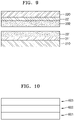
- FIG. 9 is a cross-sectional view of a triboelectric generator according to another example embodiment.
- the triboelectric generator may include first and second substrates 210 and 220 separated from each other, the first and second electrodes 211 and 221 respectively provided on the first and second substrates 210 and 220, and the first and second energy generation layers 231 and 232 respectively provided on the first and second electrodes 211 and 221.
- the first and second substrates 210 and 220 may be, for example, a substrate formed of or include a rigid material, such as, a glass substrate or a silicon substrate.
- a rigid material such as, a glass substrate or a silicon substrate.
- one or both of the first and second substrates 210 and 220 may be flexible and stretchable substrates.
- the flexible and stretchable substrates may include, for example, one or two or more combinations of PDMS, PI, Teflon, urethane, and nylon, but the example embodiment is not limited thereto.
- the substrates may have an elongation percentage of about 200% or low, the example embodiment is not limited thereto.
- the first electrode 211 is provided on the upper surface of the first substrate 210, and the second electrode 221 is provided on the lower surface of the second substrate 220.
- One or both of the first and second electrodes 211 and 221 may have flexibility and stretchability corresponding to, similar to or the same as the flexibility and stretchability of the first and second substrates 210 and 220.
- the first energy generation layer 231 is provided on the upper surface of the first electrode 211, and the second energy generation layer 232 is provided on the lower surface of the second electrode 221.
- the first energy generation layer 231 consists of a 2D material including h-BN and/or TMD.
- the first energy generation layer 231 consists of a 2D material.
- the 1 2D material may include, for example, graphene, h-BN, and/or TMD.
- the second energy generation layer 232 may include various materials having charging characteristics that may be different from the charging characteristics of the first energy generation layer 231.
- the first electrode 211 and the first energy generation layer 231 may have flexibility and stretchability corresponding to, similar to or the same as the flexibility and stretchability of the first substrate 210.
- the second electrode 221 and the second energy generation layer 232 may also have flexibility and stretchability corresponding to, similar to or the same as the flexibility and stretchability of the second substrate 220.
- One or both of the first and second substrates 210 and 220 that are flexible and stretchable may have a surface of a wavy pattern.
- the first electrode 211 and the first energy generation layer 231 may have a shape corresponding to the surface of the first substrate 210.
- the second electrode 221 and the second energy generation layer 232 may have a shape corresponding to the surface of the second substrate 220.
- both the first and second substrates 210 and 220 are provided, only one of the first and second substrates 210 and 220 may be provided.
- FIG. 10 schematically illustrates a triboelectric generator according to another example embodiment.
- the triboelectric generator may include a plurality of energy generation units 601, 602, and 603 that are vertically stacked.
- the energy generation units 601, 602, and 603 may be the triboelectric generators of various types described in the above example embodiments.
- the energy generation units 601, 602, and 603 may be serially connected to one another to increase output energy of the triboelectric generator.
- the example embodiment is not limited thereto, and the energy generation units 601, 602, and 603 may be connected to one another in parallel.
- FIG. 16 illustrates a triboelectric generator that includes three (3) energy generation units 601, 602, and 603 that are vertically stacked, the example embodiments are not limited thereto and the triboelectric generator according to the example embodiment may include various numbers of vertically stacked energy generation units.
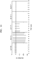
- FIG. 11 illustrates output voltages according to a thickness of an energy generation layer formed of a 2D material in a triboelectric generator
- FIG. 12 illustrates output current densities according to a thickness of an energy generation layer formed of a 2D material in a triboelectric generator according to an example embodiment.
- a MoS 2 film is used as an energy generation layer, and PDMS is used as a material contacting the MoS 2 film.
- the MoS 2 film is manufactured as follows. First, a bulk MoS 2 material is exfoliated through lithiation. Next, MoS 2 ink is manufactured by using the exfoliated MoS 2 material, and the MoS 2 ink is coated on a Cu electrode, thereby forming the MoS 2 film. As an amount of MoS 2 ink coated on the Cu electrode increases, the thickness of the MoS 2 film increases as well.
- FIG. 13 illustrates an output voltage and an output current density according to resistance of a measurement circuit, in a triboelectric generator according to an example embodiment.
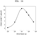
- FIG. 14 illustrates an output power density according to resistance of a measurement circuit, in a triboelectric generator according to an example embodiment.
- FIG. 13 in the case of "(b) 2 ml" of FIGS. 11 and 12 , that is, the Cu electrode is coated with the MoS 2 ink of 2 ml, the output voltages and output current densities generated as the manufactured MoS 2 film and the PDMS are in contact with each other are illustrated according to resistance of a measurement circuit connected to the triboelectric generator.
- FIG. 14 illustrates the output power density according to the resistance of the measurement circuit connected to the triboelectric generator by using the result of FIG. 13 . Referring to FIGS. 13 and 14 , it may be seen that the maximum power density is about 107.9 mW/m 2 .
- FIG. 15 illustrates charging characteristics of a MoS 2 material.
- a MoS 2 material is used as the energy generation layer, and output voltages generated when the MoS 2 material contacts other materials.
- PTFE Poly Tetra Fluoro Ethylene
- PDMS Poly DiMethyl Siloxane
- PET Poly Ethylene Terephthalate
- FIG. 16 illustrates charging characteristics of a WS 2 material.
- a MoS 2 material is used as the energy generation layer, and output voltages generated when the WS 2 material contacts other material are illustrated.
- "(a) PTFE”, “(b) PDMS”, “(c) PI”, “(d) PC”, and “(e) PET” illustrate output voltages generated when the WS 2 material contacts PTFE, PDMS, PI, PC, and PET.
- P denotes a case in which the WS 2 material is pressed to be close to other material
- “R” denotes a case in which the pressed WS 2 material is released to be separated from other material.
- the WS 2 material has friction electricity characteristics and the charging characteristics of the WS 2 material is located at a position that is more negative than the charging characteristics of PTFE.
- FIGS. 17A and 17B illustrate a method of manufacturing a triboelectric generator including graphene having a shape of a wavy pattern by using stretchability of a PDMS substrate, according to at least one example embodiment.
- FIG. 17A after a PDMS substrate is stretched, graphene is formed on an upper surface of the stretched PDMS substrate.
- a Poly Methyl Meth Acrylate (PMMA) substrate on which a Cu electrode is deposited is provided on an upper portion of the PDMS substrate.
- PMMA Poly Methyl Meth Acrylate
- FIG. 17B when the stretched PDMS substrate is contracted to an original state, the upper surface of the PDMS substrate may have the shape of a wavy pattern due to contraction. Accordingly, the graphene formed on the upper surface of the PDMS substrate may have the shape of a wavy pattern.
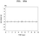
- FIGS. 18A to 18C illustrate output voltages generated as graphene and a PMMA substrate are contacted with each other, in the triboelectric generator manufactured according to the elongation percentage of PDMS in FIGS. 17A and 17B .
- FIG. 18A illustrates a case in which an elongation percentage of the PDMS substrate is 0%, in other words, the PDMS substrate is not stretched, so that graphene is not formed in a wavy pattern.
- FIG. 18B illustrates a case in which the PDMS substrate is stretched by 10% and then restored so that graphene having the shape of a wavy pattern is formed.
- FIG. 18C illustrates a case in which the PDMS substrate is stretched by 20% and then restored, so that graphene having the shape of a wavy pattern is formed.
- the triboelectric generators include the energy generation layer that may generate electric energy through friction with other material having different charging characteristics, and the energy generation layer consists of a 2D material.
- the electrode provided on the substrate, and the energy generation layer may have flexibility and stretchability corresponding to, similar to or the same as the flexibility and stretchability of the substrate. Accordingly, the triboelectric generator manufactured by using the substrate having flexibility and stretchability may effectively generate electric energy due to external environment factors such as wind, sound, or movements of a person.
- the amount of electric energy output may be increased by, for example, vertically stacking a plurality of triboelectric generators and serially connecting the triboelectric generators.
- the triboelectric generator may generate electric energy that can be used in, for example, portable electronic devices, clothes, bags, hats, gloves, or flags or by being attached on a body part of a person.
Landscapes
- Battery Electrode And Active Subsutance (AREA)
- Laminated Bodies (AREA)
- Carbon And Carbon Compounds (AREA)
- Crystals, And After-Treatments Of Crystals (AREA)
Claims (15)
- Triboelektrischer Generator, umfassend:eine erste (111) und eine zweite (121) Elektrode, die einander zugewandt sind; undeine erste Energieerzeugungsschicht (130), die sich an der ersten Elektrode befindet und dazu konfiguriert ist, elektrische Energie durch Kontakt mit mindestens einem anderen Material zu erzeugen, und dadurch gekennzeichnet, dass die erste Energieerzeugungsschicht aus einem zweidimensionalen Material besteht, das eine Kristallstruktur einer zweidimensionalen Form aufweist.
- Triboelektrischer Generator nach Anspruch 1, wobei das zweidimensionale Material mindestens eines von hexagonalem Bornitrid und Übergangsmetall-Dichalkogenid umfasst und optional wobei das zweidimensionale Material eine einzelne Schicht oder eine mehrschichtige Struktur aufweist.
- Triboelektrischer Generator nach Anspruch 2, wobei das Übergangsmetall-Dichalkogenid eines von Mo, W, Nb, V, Ta, Ti, Zr, Hf, Tc, Re, Cu, Ga, In, Sn, Ge und Pb und eines von S, Se und Te umfasst.
- Triboelektrischer Generator nach einem vorhergehenden Anspruch, wobei das zweidimensionale Material eine Dicke von 0,3 nm bis 1000 nm aufweist.
- Triboelektrischer Generator nach einem vorhergehenden Anspruch, ferner umfassend einen Abstandshalter (150) zwischen der ersten Elektrode (111) und der zweiten Elektrode (121).
- Triboelektrischer Generator nach einem vorhergehenden Anspruch, wobei die erste Energieschicht (130) elektrische Energie durch Kontakt mit der zweiten Elektrode (121) erzeugt.
- Triboelektrischer Generator nach einem vorhergehenden Anspruch, ferner umfassend mindestens eines von einem ersten Substrat (110), das mit der ersten Elektrode (111) und der ersten Energieerzeugungsschicht (130) verbunden ist, und einem zweiten Substrat (120), das mit der zweiten Elektrode (121) verbunden ist,
und optional wobei die erste Energieerzeugungsschicht (130) dazu konfiguriert ist, elektrische Energie durch Kontakt mit der zweiten Elektrode (121) oder dem zweiten Substrat (120) zu erzeugen. - Triboelektrischer Generator nach Anspruch 7, wobei mindestens eines von dem ersten (110) und dem zweiten Substrat (120) dehnbar ist, und
optional wobei das mindestens eine von dem ersten und dem zweiten Substrat einen Dehnungsprozentsatz von etwa 200 % oder weniger aufweist. - Triboelektrischer Generator nach Anspruch 7 oder 8, wobei das mindestens eine von dem ersten (110) und dem zweiten (120) Substrat mindestens eines von Polydimethylsiloxan, Polyimid, Teflon, Urethan und Nylon umfasst.
- Triboelektrischer Generator nach Anspruch 7, 8 oder 9, wobei das mindestens eine von dem ersten (110') und dem zweiten Substrat (120) eine Oberfläche aufweist, die eine wellenförmige Form aufweist,
und optional wobei die erste Elektrode (111') und die erste Energieerzeugungsschicht (130') eine Form aufweisen, die einer Oberfläche des ersten Substrats entspricht, und die zweite Elektrode eine Form aufweist, die einer Oberfläche des zweiten Substrats entspricht. - Triboelektrischer Generator nach Anspruch 7, 8, 9 oder 10, wobei mindestens eine von der ersten (111) und der zweiten (121) Elektrode mindestens eines von Kohlenstoff-Nanoröhrchen, Graphen, Ag-Nanodraht, Metall und Metallgeflecht umfasst.
- Triboelektrischer Generator nach einem vorhergehenden Anspruch, ferner umfassend eine zweite Energieerzeugungsschicht (232), die sich an der zweiten Elektrode (221) befindet und dazu konfiguriert ist, durch Kontakt mit der ersten Energieerzeugungsschicht (231) elektrische Energie zu erzeugen,
und optional ferner umfassend mindestens eines von einem ersten Substrat (210), das mit der ersten Elektrode (211) und der ersten Energieerzeugungsschicht (231) verbunden ist, und einem zweiten Substrat (220), das mit der zweiten Elektrode (221) und der zweiten Energieerzeugungsschicht (232) verbunden ist. - Triboelektrischer Generator nach einem vorhergehenden Anspruch, wobei die erste (111) und die zweite Elektrode (121) dehnbar sind.
- Triboelektrischer Generator, umfassend:eine Vielzahl von Energieerzeugungseinheiten (601, 602, 603), die gestapelt sind,wobei mindestens eine der Energieerzeugungseinheiten ein triboelektrischer Generator nach einem vorhergehenden Anspruch ist.
- Triboelektrischer Generator nach Anspruch 14, wobei die Energieerzeugungseinheiten (601, 602, 603) in Reihe miteinander verbunden sind.
Applications Claiming Priority (2)
| Application Number | Priority Date | Filing Date | Title |
|---|---|---|---|
| KR20150056003 | 2015-04-21 | ||
| KR1020150138615A KR102553838B1 (ko) | 2015-04-21 | 2015-10-01 | 마찰전기 발전기 |
Publications (3)
| Publication Number | Publication Date |
|---|---|
| EP3086460A2 EP3086460A2 (de) | 2016-10-26 |
| EP3086460A3 EP3086460A3 (de) | 2017-03-29 |
| EP3086460B1 true EP3086460B1 (de) | 2022-12-21 |
Family
ID=55701765
Family Applications (1)
| Application Number | Title | Priority Date | Filing Date |
|---|---|---|---|
| EP16163889.5A Active EP3086460B1 (de) | 2015-04-21 | 2016-04-05 | Triboelektrischer generator |
Country Status (3)
| Country | Link |
|---|---|
| US (1) | US10199958B2 (de) |
| EP (1) | EP3086460B1 (de) |
| CN (1) | CN106067739B (de) |
Families Citing this family (27)
| Publication number | Priority date | Publication date | Assignee | Title |
|---|---|---|---|---|
| WO2015140710A2 (en) * | 2014-03-18 | 2015-09-24 | Fondazione Istituto Italiano Di Tecnologia | Triboelectric composite for mechanical energy harvesting and sensing |
| KR101544326B1 (ko) * | 2014-10-15 | 2015-08-12 | 성균관대학교산학협력단 | 강유전 또는 압전 물질층 상의 2차원 구조의 물질을 이용하여 투명성 및 기계적 특성이 향상된 정전기 에너지 발전 소자 |
| KR101557245B1 (ko) * | 2014-12-03 | 2015-10-21 | 성균관대학교산학협력단 | 타이어 코드지용 섬유를 이용한 정전기 에너지 발생장치 |
| US10199958B2 (en) * | 2015-04-21 | 2019-02-05 | Samsung Electronics Co., Ltd. | Triboelectric generator |
| CN104811089A (zh) * | 2015-05-19 | 2015-07-29 | 京东方科技集团股份有限公司 | 一种摩擦生电装置及其制作方法、电子设备和可穿戴设备 |
| CN105207517B (zh) * | 2015-08-26 | 2017-08-25 | 京东方科技集团股份有限公司 | 摩擦发电装置及其制造方法 |
| JP6645161B2 (ja) * | 2015-12-11 | 2020-02-14 | 株式会社リコー | 発電装置 |
| US10900930B2 (en) * | 2016-07-15 | 2021-01-26 | United States Of America As Represented By The Administrator Of Nasa | Method for phonon assisted creation and annihilation of subsurface electric dipoles |
| CN106602924A (zh) * | 2016-11-18 | 2017-04-26 | 北京纳米能源与系统研究所 | 一种收集振动能量的摩擦纳米发电机和振动传感器 |
| EP3565781B1 (de) | 2016-12-22 | 2026-02-18 | Board of Trustees of the University of Arkansas | Energiegewinnungsvorrichtungen und sensoren sowie verfahren zur herstellung und verwendung davon |
| CN109149992B (zh) * | 2017-06-15 | 2020-03-10 | 北京纳米能源与系统研究所 | 改进型摩擦纳米发电机 |
| US10804818B2 (en) * | 2017-06-30 | 2020-10-13 | Toyota Motor Engineering & Manufacturing North America, Inc. | Triboelectric generator and network for mechanical energy harvesting |
| WO2019073317A1 (en) * | 2017-10-11 | 2019-04-18 | Sabic Global Technologies B.V. | GRAPHENE POLYMER-OXIDE TRIBOELECTRIC MATERIALS, METHODS OF MAKING THE SAME, AND USES THEREOF |
| KR102213229B1 (ko) * | 2017-11-22 | 2021-02-04 | 송찰스기석 | 마찰전기 발전 소자 및 그 제조방법 |
| US10774618B2 (en) * | 2018-03-16 | 2020-09-15 | Baker Hughes, A Ge Company, Llc | Autonomous downhole power generator module |
| CN108233762B (zh) * | 2018-03-22 | 2023-12-22 | 大连理工大学 | 一种全方位多模式收集机械能的柔性可穿戴摩擦纳米发电机 |
| DE102018221053A1 (de) * | 2018-04-05 | 2019-10-10 | Continental Reifen Deutschland Gmbh | Vorrichtung zum Messen einer mechanischen Kraft, umfassend eine erste, zweite, dritte, vierte und fünfte Schicht sowie die Verwendungen der Vorrichtung und Reifen oder technischer Gummiartikel umfassend die Vorrichtung |
| PE20211258A1 (es) * | 2018-05-30 | 2021-07-14 | Univ Arkansas | Dispositivos y sensores de recoleccion de energia y metodos de fabricacion y uso de estos |
| US11276644B2 (en) * | 2018-12-17 | 2022-03-15 | Intel Corporation | Integrated circuits and methods for forming thin film crystal layers |
| CN109889081B (zh) * | 2019-04-10 | 2020-09-04 | 苏州大学 | 一种单电极模式的可拉伸摩擦纳米发电机及制备方法 |
| US12091313B2 (en) | 2019-08-26 | 2024-09-17 | The Research Foundation For The State University Of New York | Electrodynamically levitated actuator |
| KR20210077157A (ko) * | 2019-12-17 | 2021-06-25 | 송찰스기석 | 분리막이 적용된 마찰전기 발전 소자 및 그 제조방법 |
| CN111245081B (zh) * | 2020-01-21 | 2023-06-20 | 电子科技大学 | 自供能汽车尾气传感器与方法 |
| US11478191B1 (en) * | 2020-04-03 | 2022-10-25 | Esatto Healthcare, Inc. | Smart mask for COVID-19 screening, tracking and monitoring |
| CA3176117A1 (en) | 2020-04-22 | 2021-10-28 | Paul Thibado | Device for ambient thermal and vibration energy harvesting |
| CN113783471B (zh) * | 2021-07-16 | 2023-12-08 | 浙江大学 | 一种薄膜动态半导体-聚合物半导体异质结直流发电机及其制备方法 |
| CN114106639A (zh) * | 2021-11-19 | 2022-03-01 | 兰州理工大学 | 一种高摩擦电荷密度、耐磨损摩擦电材料及其应用 |
Family Cites Families (24)
| Publication number | Priority date | Publication date | Assignee | Title |
|---|---|---|---|---|
| KR101435999B1 (ko) | 2007-12-07 | 2014-08-29 | 삼성전자주식회사 | 도펀트로 도핑된 산화그라펜의 환원물, 이를 포함하는 박막및 투명전극 |
| KR101450591B1 (ko) | 2008-06-05 | 2014-10-17 | 삼성전자주식회사 | 탄소나노튜브 엔 도핑 물질 및 방법, 이를 이용한 소자 |
| KR101634753B1 (ko) | 2008-11-28 | 2016-06-30 | 삼성전자주식회사 | 탄소나노튜브 엔 도핑 물질 및 이를 이용한 엔 도핑 방법 |
| US8803406B2 (en) | 2010-11-30 | 2014-08-12 | KAIST (Korea Advanced Institute of Science and Technology) | Flexible nanocomposite generator and method for manufacturing the same |
| US9178446B2 (en) | 2011-08-30 | 2015-11-03 | Georgia Tech Research Corporation | Triboelectric generator |
| KR101471845B1 (ko) | 2012-06-29 | 2014-12-11 | 엘지디스플레이 주식회사 | 입력 시스템을 구비한 표시장치 및 그 구동 방법 |
| US9812993B2 (en) | 2012-09-21 | 2017-11-07 | Georgia Tech Research Corporation | Single electrode triboelectric generator |
| US9790928B2 (en) * | 2012-09-21 | 2017-10-17 | Georgia Tech Research Corporation | Triboelectric generators and sensors |
| US9985554B2 (en) | 2013-03-01 | 2018-05-29 | Georgia Tech Research Corporation | Triboelectric nanogenerator |
| KR101992495B1 (ko) | 2013-02-07 | 2019-06-25 | 도레이첨단소재 주식회사 | 유연기판 소재용 측면 봉지재 |
| US9484842B2 (en) | 2013-03-01 | 2016-11-01 | Georgia Tech Research Corporation | Segmentally structured disk triboelectric nanogenerator |
| US9571009B2 (en) | 2013-03-01 | 2017-02-14 | Georgia Tech Research Corporation | Rotating cylindrical and spherical triboelectric generators |
| KR20140126607A (ko) | 2013-04-23 | 2014-10-31 | 삼성전자주식회사 | 터치입력 모듈과 에너지 발생소자를 포함하는 스마트 장치 및 이 스마트 장치의 동작 방법 |
| KR101498595B1 (ko) | 2013-05-31 | 2015-03-04 | 전자부품연구원 | 마찰전기 발생장치 |
| CN104242723B (zh) | 2013-06-13 | 2019-06-04 | 北京纳米能源与系统研究所 | 单电极摩擦纳米发电机、发电方法和自驱动追踪装置 |
| CN104300828B (zh) | 2013-07-19 | 2017-06-16 | 纳米新能源(唐山)有限责任公司 | 一种摩擦发电机 |
| KR102103987B1 (ko) | 2013-09-02 | 2020-04-24 | 삼성전자주식회사 | 직물 기반의 에너지 제너레이터 |
| US10199958B2 (en) * | 2015-04-21 | 2019-02-05 | Samsung Electronics Co., Ltd. | Triboelectric generator |
| US10305020B2 (en) * | 2015-05-15 | 2019-05-28 | Ricoh Company, Ltd. | Element and electric generator |
| KR102455431B1 (ko) * | 2015-06-02 | 2022-10-17 | 삼성전자주식회사 | 마찰전기 발전기 |
| JP6645161B2 (ja) * | 2015-12-11 | 2020-02-14 | 株式会社リコー | 発電装置 |
| KR102578823B1 (ko) * | 2016-05-10 | 2023-09-15 | 삼성전자주식회사 | 마찰전기 발전기 |
| US10770990B2 (en) * | 2016-05-10 | 2020-09-08 | Samsung Electronics Co., Ltd. | Triboelectric generator |
| KR102600148B1 (ko) * | 2016-08-23 | 2023-11-08 | 삼성전자주식회사 | 표면 플라즈몬 공명을 이용한 마찰전기 발전기 |
-
2016
- 2016-02-22 US US15/049,726 patent/US10199958B2/en active Active
- 2016-04-05 EP EP16163889.5A patent/EP3086460B1/de active Active
- 2016-04-19 CN CN201610244475.4A patent/CN106067739B/zh active Active
Also Published As
| Publication number | Publication date |
|---|---|
| US20160315561A1 (en) | 2016-10-27 |
| CN106067739B (zh) | 2020-01-17 |
| EP3086460A3 (de) | 2017-03-29 |
| US10199958B2 (en) | 2019-02-05 |
| CN106067739A (zh) | 2016-11-02 |
| EP3086460A2 (de) | 2016-10-26 |
Similar Documents
| Publication | Publication Date | Title |
|---|---|---|
| EP3086460B1 (de) | Triboelektrischer generator | |
| KR102553838B1 (ko) | 마찰전기 발전기 | |
| Yang et al. | Recent developments in flexible thermoelectric devices | |
| Zong et al. | Graphene-based thermoelectrics | |
| Jin et al. | Cellulose fiber-based hierarchical porous bismuth telluride for high-performance flexible and tailorable thermoelectrics | |
| Lee et al. | All-in-one energy harvesting and storage devices | |
| Lu et al. | Piezoelectric nanogenerator using p-type ZnO nanowire arrays | |
| An et al. | High-performance flexible thermoelectric generator by control of electronic structure of directly spun carbon nanotube webs with various molecular dopants | |
| Hu et al. | Recent advancements in nanogenerators for energy harvesting | |
| Liu et al. | Improvement in the piezoelectric performance of a ZnO nanogenerator by a combination of chemical doping and interfacial modification | |
| Hewitt et al. | Multilayered carbon nanotube/polymer composite based thermoelectric fabrics | |
| Johar et al. | Highly durable piezoelectric nanogenerator by heteroepitaxy of GaN nanowires on Cu foil for enhanced output using ambient actuation sources | |
| Yan et al. | Highly thermoelectric ZnO@ MXene (Ti3C2T x) composite films grown by atomic layer deposition | |
| Gan et al. | Efficient photovoltaic conversion of graphene–carbon nanotube hybrid films grown from solid precursors | |
| JP6392959B2 (ja) | 温度検出システム | |
| Piao et al. | Preparation and characterization of expanded graphite polymer composite films for thermoelectric applications | |
| Kwon et al. | Graphene based nanogenerator for energy harvesting | |
| CN107932475B (zh) | 一种仿生手臂及采用该仿生手臂的机器人 | |
| US10770989B2 (en) | Electrode structure, triboelectric generator including the same, and method of manufacturing the electrode structure | |
| Nguyen et al. | based ZnO nanogenerator using contact electrification and piezoelectric effects | |
| Han et al. | Attachable piezoelectric nanogenerators using collision-induced strain of vertically grown hollow MoS2 nanoflakes | |
| Das et al. | High-performance paper-based thermoelectric generator from Cu2SnS3 nanocubes and bulk-traced bismuth | |
| Zhang et al. | High-performance thermoelectric flexible Ag2Se-based films with wave-shaped buckling via a thermal diffusion method | |
| Kocaman Kabil et al. | Harnessing thermoelectric power in self-healing wearables: a review | |
| Li et al. | Programmable and functional electrothermal bimorph actuators based on large-area anisotropic carbon nanotube paper |
Legal Events
| Date | Code | Title | Description |
|---|---|---|---|
| PUAI | Public reference made under article 153(3) epc to a published international application that has entered the european phase |
Free format text: ORIGINAL CODE: 0009012 |
|
| AK | Designated contracting states |
Kind code of ref document: A2 Designated state(s): AL AT BE BG CH CY CZ DE DK EE ES FI FR GB GR HR HU IE IS IT LI LT LU LV MC MK MT NL NO PL PT RO RS SE SI SK SM TR |
|
| AX | Request for extension of the european patent |
Extension state: BA ME |
|
| RIC1 | Information provided on ipc code assigned before grant |
Ipc: H02N 1/04 20060101AFI20161021BHEP |
|
| PUAL | Search report despatched |
Free format text: ORIGINAL CODE: 0009013 |
|
| AK | Designated contracting states |
Kind code of ref document: A3 Designated state(s): AL AT BE BG CH CY CZ DE DK EE ES FI FR GB GR HR HU IE IS IT LI LT LU LV MC MK MT NL NO PL PT RO RS SE SI SK SM TR |
|
| AX | Request for extension of the european patent |
Extension state: BA ME |
|
| RIC1 | Information provided on ipc code assigned before grant |
Ipc: H02N 1/04 20060101AFI20170220BHEP |
|
| STAA | Information on the status of an ep patent application or granted ep patent |
Free format text: STATUS: REQUEST FOR EXAMINATION WAS MADE |
|
| 17P | Request for examination filed |
Effective date: 20170814 |
|
| RBV | Designated contracting states (corrected) |
Designated state(s): AL AT BE BG CH CY CZ DE DK EE ES FI FR GB GR HR HU IE IS IT LI LT LU LV MC MK MT NL NO PL PT RO RS SE SI SK SM TR |
|
| STAA | Information on the status of an ep patent application or granted ep patent |
Free format text: STATUS: EXAMINATION IS IN PROGRESS |
|
| 17Q | First examination report despatched |
Effective date: 20200416 |
|
| GRAP | Despatch of communication of intention to grant a patent |
Free format text: ORIGINAL CODE: EPIDOSNIGR1 |
|
| STAA | Information on the status of an ep patent application or granted ep patent |
Free format text: STATUS: GRANT OF PATENT IS INTENDED |
|
| INTG | Intention to grant announced |
Effective date: 20220113 |
|
| GRAJ | Information related to disapproval of communication of intention to grant by the applicant or resumption of examination proceedings by the epo deleted |
Free format text: ORIGINAL CODE: EPIDOSDIGR1 |
|
| STAA | Information on the status of an ep patent application or granted ep patent |
Free format text: STATUS: EXAMINATION IS IN PROGRESS |
|
| INTC | Intention to grant announced (deleted) | ||
| GRAP | Despatch of communication of intention to grant a patent |
Free format text: ORIGINAL CODE: EPIDOSNIGR1 |
|
| STAA | Information on the status of an ep patent application or granted ep patent |
Free format text: STATUS: GRANT OF PATENT IS INTENDED |
|
| INTG | Intention to grant announced |
Effective date: 20220711 |
|
| GRAS | Grant fee paid |
Free format text: ORIGINAL CODE: EPIDOSNIGR3 |
|
| GRAA | (expected) grant |
Free format text: ORIGINAL CODE: 0009210 |
|
| STAA | Information on the status of an ep patent application or granted ep patent |
Free format text: STATUS: THE PATENT HAS BEEN GRANTED |
|
| AK | Designated contracting states |
Kind code of ref document: B1 Designated state(s): AL AT BE BG CH CY CZ DE DK EE ES FI FR GB GR HR HU IE IS IT LI LT LU LV MC MK MT NL NO PL PT RO RS SE SI SK SM TR |
|
| REG | Reference to a national code |
Ref country code: GB Ref legal event code: FG4D |
|
| REG | Reference to a national code |
Ref country code: CH Ref legal event code: EP |
|
| REG | Reference to a national code |
Ref country code: DE Ref legal event code: R096 Ref document number: 602016076975 Country of ref document: DE |
|
| REG | Reference to a national code |
Ref country code: AT Ref legal event code: REF Ref document number: 1539640 Country of ref document: AT Kind code of ref document: T Effective date: 20230115 |
|
| REG | Reference to a national code |
Ref country code: IE Ref legal event code: FG4D |
|
| REG | Reference to a national code |
Ref country code: LT Ref legal event code: MG9D |
|
| REG | Reference to a national code |
Ref country code: NL Ref legal event code: MP Effective date: 20221221 |
|
| PG25 | Lapsed in a contracting state [announced via postgrant information from national office to epo] |
Ref country code: SE Free format text: LAPSE BECAUSE OF FAILURE TO SUBMIT A TRANSLATION OF THE DESCRIPTION OR TO PAY THE FEE WITHIN THE PRESCRIBED TIME-LIMIT Effective date: 20221221 Ref country code: NO Free format text: LAPSE BECAUSE OF FAILURE TO SUBMIT A TRANSLATION OF THE DESCRIPTION OR TO PAY THE FEE WITHIN THE PRESCRIBED TIME-LIMIT Effective date: 20230321 Ref country code: LT Free format text: LAPSE BECAUSE OF FAILURE TO SUBMIT A TRANSLATION OF THE DESCRIPTION OR TO PAY THE FEE WITHIN THE PRESCRIBED TIME-LIMIT Effective date: 20221221 Ref country code: FI Free format text: LAPSE BECAUSE OF FAILURE TO SUBMIT A TRANSLATION OF THE DESCRIPTION OR TO PAY THE FEE WITHIN THE PRESCRIBED TIME-LIMIT Effective date: 20221221 |
|
| REG | Reference to a national code |
Ref country code: AT Ref legal event code: MK05 Ref document number: 1539640 Country of ref document: AT Kind code of ref document: T Effective date: 20221221 |
|
| PG25 | Lapsed in a contracting state [announced via postgrant information from national office to epo] |
Ref country code: RS Free format text: LAPSE BECAUSE OF FAILURE TO SUBMIT A TRANSLATION OF THE DESCRIPTION OR TO PAY THE FEE WITHIN THE PRESCRIBED TIME-LIMIT Effective date: 20221221 Ref country code: LV Free format text: LAPSE BECAUSE OF FAILURE TO SUBMIT A TRANSLATION OF THE DESCRIPTION OR TO PAY THE FEE WITHIN THE PRESCRIBED TIME-LIMIT Effective date: 20221221 Ref country code: HR Free format text: LAPSE BECAUSE OF FAILURE TO SUBMIT A TRANSLATION OF THE DESCRIPTION OR TO PAY THE FEE WITHIN THE PRESCRIBED TIME-LIMIT Effective date: 20221221 Ref country code: GR Free format text: LAPSE BECAUSE OF FAILURE TO SUBMIT A TRANSLATION OF THE DESCRIPTION OR TO PAY THE FEE WITHIN THE PRESCRIBED TIME-LIMIT Effective date: 20230322 |
|
| P01 | Opt-out of the competence of the unified patent court (upc) registered |
Effective date: 20230520 |
|
| PG25 | Lapsed in a contracting state [announced via postgrant information from national office to epo] |
Ref country code: NL Free format text: LAPSE BECAUSE OF FAILURE TO SUBMIT A TRANSLATION OF THE DESCRIPTION OR TO PAY THE FEE WITHIN THE PRESCRIBED TIME-LIMIT Effective date: 20221221 |
|
| PG25 | Lapsed in a contracting state [announced via postgrant information from national office to epo] |
Ref country code: SM Free format text: LAPSE BECAUSE OF FAILURE TO SUBMIT A TRANSLATION OF THE DESCRIPTION OR TO PAY THE FEE WITHIN THE PRESCRIBED TIME-LIMIT Effective date: 20221221 Ref country code: RO Free format text: LAPSE BECAUSE OF FAILURE TO SUBMIT A TRANSLATION OF THE DESCRIPTION OR TO PAY THE FEE WITHIN THE PRESCRIBED TIME-LIMIT Effective date: 20221221 Ref country code: PT Free format text: LAPSE BECAUSE OF FAILURE TO SUBMIT A TRANSLATION OF THE DESCRIPTION OR TO PAY THE FEE WITHIN THE PRESCRIBED TIME-LIMIT Effective date: 20230421 Ref country code: ES Free format text: LAPSE BECAUSE OF FAILURE TO SUBMIT A TRANSLATION OF THE DESCRIPTION OR TO PAY THE FEE WITHIN THE PRESCRIBED TIME-LIMIT Effective date: 20221221 Ref country code: EE Free format text: LAPSE BECAUSE OF FAILURE TO SUBMIT A TRANSLATION OF THE DESCRIPTION OR TO PAY THE FEE WITHIN THE PRESCRIBED TIME-LIMIT Effective date: 20221221 Ref country code: CZ Free format text: LAPSE BECAUSE OF FAILURE TO SUBMIT A TRANSLATION OF THE DESCRIPTION OR TO PAY THE FEE WITHIN THE PRESCRIBED TIME-LIMIT Effective date: 20221221 Ref country code: AT Free format text: LAPSE BECAUSE OF FAILURE TO SUBMIT A TRANSLATION OF THE DESCRIPTION OR TO PAY THE FEE WITHIN THE PRESCRIBED TIME-LIMIT Effective date: 20221221 |
|
| PG25 | Lapsed in a contracting state [announced via postgrant information from national office to epo] |
Ref country code: SK Free format text: LAPSE BECAUSE OF FAILURE TO SUBMIT A TRANSLATION OF THE DESCRIPTION OR TO PAY THE FEE WITHIN THE PRESCRIBED TIME-LIMIT Effective date: 20221221 Ref country code: PL Free format text: LAPSE BECAUSE OF FAILURE TO SUBMIT A TRANSLATION OF THE DESCRIPTION OR TO PAY THE FEE WITHIN THE PRESCRIBED TIME-LIMIT Effective date: 20221221 Ref country code: IS Free format text: LAPSE BECAUSE OF FAILURE TO SUBMIT A TRANSLATION OF THE DESCRIPTION OR TO PAY THE FEE WITHIN THE PRESCRIBED TIME-LIMIT Effective date: 20230421 Ref country code: AL Free format text: LAPSE BECAUSE OF FAILURE TO SUBMIT A TRANSLATION OF THE DESCRIPTION OR TO PAY THE FEE WITHIN THE PRESCRIBED TIME-LIMIT Effective date: 20221221 |
|
| REG | Reference to a national code |
Ref country code: DE Ref legal event code: R097 Ref document number: 602016076975 Country of ref document: DE |
|
| PLBE | No opposition filed within time limit |
Free format text: ORIGINAL CODE: 0009261 |
|
| STAA | Information on the status of an ep patent application or granted ep patent |
Free format text: STATUS: NO OPPOSITION FILED WITHIN TIME LIMIT |
|
| PG25 | Lapsed in a contracting state [announced via postgrant information from national office to epo] |
Ref country code: DK Free format text: LAPSE BECAUSE OF FAILURE TO SUBMIT A TRANSLATION OF THE DESCRIPTION OR TO PAY THE FEE WITHIN THE PRESCRIBED TIME-LIMIT Effective date: 20221221 |
|
| 26N | No opposition filed |
Effective date: 20230922 |
|
| REG | Reference to a national code |
Ref country code: CH Ref legal event code: PL |
|
| PG25 | Lapsed in a contracting state [announced via postgrant information from national office to epo] |
Ref country code: LU Free format text: LAPSE BECAUSE OF NON-PAYMENT OF DUE FEES Effective date: 20230405 |
|
| REG | Reference to a national code |
Ref country code: BE Ref legal event code: MM Effective date: 20230430 |
|
| PG25 | Lapsed in a contracting state [announced via postgrant information from national office to epo] |
Ref country code: MC Free format text: LAPSE BECAUSE OF FAILURE TO SUBMIT A TRANSLATION OF THE DESCRIPTION OR TO PAY THE FEE WITHIN THE PRESCRIBED TIME-LIMIT Effective date: 20221221 |
|
| PG25 | Lapsed in a contracting state [announced via postgrant information from national office to epo] |
Ref country code: SI Free format text: LAPSE BECAUSE OF FAILURE TO SUBMIT A TRANSLATION OF THE DESCRIPTION OR TO PAY THE FEE WITHIN THE PRESCRIBED TIME-LIMIT Effective date: 20221221 Ref country code: MC Free format text: LAPSE BECAUSE OF FAILURE TO SUBMIT A TRANSLATION OF THE DESCRIPTION OR TO PAY THE FEE WITHIN THE PRESCRIBED TIME-LIMIT Effective date: 20221221 Ref country code: LI Free format text: LAPSE BECAUSE OF NON-PAYMENT OF DUE FEES Effective date: 20230430 Ref country code: CH Free format text: LAPSE BECAUSE OF NON-PAYMENT OF DUE FEES Effective date: 20230430 |
|
| REG | Reference to a national code |
Ref country code: IE Ref legal event code: MM4A |
|
| PG25 | Lapsed in a contracting state [announced via postgrant information from national office to epo] |
Ref country code: BE Free format text: LAPSE BECAUSE OF NON-PAYMENT OF DUE FEES Effective date: 20230430 |
|
| PG25 | Lapsed in a contracting state [announced via postgrant information from national office to epo] |
Ref country code: IE Free format text: LAPSE BECAUSE OF NON-PAYMENT OF DUE FEES Effective date: 20230405 |
|
| PG25 | Lapsed in a contracting state [announced via postgrant information from national office to epo] |
Ref country code: IE Free format text: LAPSE BECAUSE OF NON-PAYMENT OF DUE FEES Effective date: 20230405 |
|
| PG25 | Lapsed in a contracting state [announced via postgrant information from national office to epo] |
Ref country code: IT Free format text: LAPSE BECAUSE OF FAILURE TO SUBMIT A TRANSLATION OF THE DESCRIPTION OR TO PAY THE FEE WITHIN THE PRESCRIBED TIME-LIMIT Effective date: 20221221 |
|
| PG25 | Lapsed in a contracting state [announced via postgrant information from national office to epo] |
Ref country code: BG Free format text: LAPSE BECAUSE OF FAILURE TO SUBMIT A TRANSLATION OF THE DESCRIPTION OR TO PAY THE FEE WITHIN THE PRESCRIBED TIME-LIMIT Effective date: 20221221 |
|
| PG25 | Lapsed in a contracting state [announced via postgrant information from national office to epo] |
Ref country code: BG Free format text: LAPSE BECAUSE OF FAILURE TO SUBMIT A TRANSLATION OF THE DESCRIPTION OR TO PAY THE FEE WITHIN THE PRESCRIBED TIME-LIMIT Effective date: 20221221 |
|
| PGFP | Annual fee paid to national office [announced via postgrant information from national office to epo] |
Ref country code: DE Payment date: 20250311 Year of fee payment: 10 |
|
| PG25 | Lapsed in a contracting state [announced via postgrant information from national office to epo] |
Ref country code: CY Free format text: LAPSE BECAUSE OF FAILURE TO SUBMIT A TRANSLATION OF THE DESCRIPTION OR TO PAY THE FEE WITHIN THE PRESCRIBED TIME-LIMIT; INVALID AB INITIO Effective date: 20160405 |
|
| PG25 | Lapsed in a contracting state [announced via postgrant information from national office to epo] |
Ref country code: HU Free format text: LAPSE BECAUSE OF FAILURE TO SUBMIT A TRANSLATION OF THE DESCRIPTION OR TO PAY THE FEE WITHIN THE PRESCRIBED TIME-LIMIT; INVALID AB INITIO Effective date: 20160405 |
|
| PG25 | Lapsed in a contracting state [announced via postgrant information from national office to epo] |
Ref country code: TR Free format text: LAPSE BECAUSE OF FAILURE TO SUBMIT A TRANSLATION OF THE DESCRIPTION OR TO PAY THE FEE WITHIN THE PRESCRIBED TIME-LIMIT Effective date: 20221221 |
|
| PGFP | Annual fee paid to national office [announced via postgrant information from national office to epo] |
Ref country code: GB Payment date: 20260323 Year of fee payment: 11 |
|
| PGFP | Annual fee paid to national office [announced via postgrant information from national office to epo] |
Ref country code: FR Payment date: 20260323 Year of fee payment: 11 |