EP3086576A1 - Lötfreier modulverbinder für eine hörhilfevorrichtung - Google Patents
Lötfreier modulverbinder für eine hörhilfevorrichtung Download PDFInfo
- Publication number
- EP3086576A1 EP3086576A1 EP16166704.3A EP16166704A EP3086576A1 EP 3086576 A1 EP3086576 A1 EP 3086576A1 EP 16166704 A EP16166704 A EP 16166704A EP 3086576 A1 EP3086576 A1 EP 3086576A1
- Authority
- EP
- European Patent Office
- Prior art keywords
- ucm
- hearing assistance
- lds
- subject matter
- assistance device
- Prior art date
- Legal status (The legal status is an assumption and is not a legal conclusion. Google has not performed a legal analysis and makes no representation as to the accuracy of the status listed.)
- Granted
Links
Images


Classifications
-
- H—ELECTRICITY
- H04—ELECTRIC COMMUNICATION TECHNIQUE
- H04R—LOUDSPEAKERS, MICROPHONES, GRAMOPHONE PICK-UPS OR LIKE ACOUSTIC ELECTROMECHANICAL TRANSDUCERS; ELECTRIC HEARING AIDS; PUBLIC ADDRESS SYSTEMS
- H04R25/00—Electric hearing aids
- H04R25/65—Housing parts, e.g. shells, tips or moulds, or their manufacture
- H04R25/658—Manufacture of housing parts
-
- H—ELECTRICITY
- H04—ELECTRIC COMMUNICATION TECHNIQUE
- H04R—LOUDSPEAKERS, MICROPHONES, GRAMOPHONE PICK-UPS OR LIKE ACOUSTIC ELECTROMECHANICAL TRANSDUCERS; ELECTRIC HEARING AIDS; PUBLIC ADDRESS SYSTEMS
- H04R25/00—Electric hearing aids
- H04R25/60—Mounting or interconnection of hearing aid parts, e.g. inside tips, housings or to ossicles
- H04R25/609—Mounting or interconnection of hearing aid parts, e.g. inside tips, housings or to ossicles of circuitry
-
- H—ELECTRICITY
- H01—ELECTRIC ELEMENTS
- H01R—ELECTRICALLY-CONDUCTIVE CONNECTIONS; STRUCTURAL ASSOCIATIONS OF A PLURALITY OF MUTUALLY-INSULATED ELECTRICAL CONNECTING ELEMENTS; COUPLING DEVICES; CURRENT COLLECTORS
- H01R12/00—Structural associations of a plurality of mutually-insulated electrical connecting elements, specially adapted for printed circuits, e.g. printed circuit boards [PCB], flat or ribbon cables, or like generally planar structures, e.g. terminal strips, terminal blocks; Coupling devices specially adapted for printed circuits, flat or ribbon cables, or like generally planar structures; Terminals specially adapted for contact with, or insertion into, printed circuits, flat or ribbon cables, or like generally planar structures
- H01R12/70—Coupling devices
- H01R12/7076—Coupling devices for connection between PCB and component, e.g. display
-
- H—ELECTRICITY
- H01—ELECTRIC ELEMENTS
- H01R—ELECTRICALLY-CONDUCTIVE CONNECTIONS; STRUCTURAL ASSOCIATIONS OF A PLURALITY OF MUTUALLY-INSULATED ELECTRICAL CONNECTING ELEMENTS; COUPLING DEVICES; CURRENT COLLECTORS
- H01R12/00—Structural associations of a plurality of mutually-insulated electrical connecting elements, specially adapted for printed circuits, e.g. printed circuit boards [PCB], flat or ribbon cables, or like generally planar structures, e.g. terminal strips, terminal blocks; Coupling devices specially adapted for printed circuits, flat or ribbon cables, or like generally planar structures; Terminals specially adapted for contact with, or insertion into, printed circuits, flat or ribbon cables, or like generally planar structures
- H01R12/70—Coupling devices
- H01R12/71—Coupling devices for rigid printing circuits or like structures
- H01R12/712—Coupling devices for rigid printing circuits or like structures co-operating with the surface of the printed circuit or with a coupling device exclusively provided on the surface of the printed circuit
- H01R12/714—Coupling devices for rigid printing circuits or like structures co-operating with the surface of the printed circuit or with a coupling device exclusively provided on the surface of the printed circuit with contacts abutting directly the printed circuit; Button contacts therefore provided on the printed circuit
-
- H—ELECTRICITY
- H01—ELECTRIC ELEMENTS
- H01R—ELECTRICALLY-CONDUCTIVE CONNECTIONS; STRUCTURAL ASSOCIATIONS OF A PLURALITY OF MUTUALLY-INSULATED ELECTRICAL CONNECTING ELEMENTS; COUPLING DEVICES; CURRENT COLLECTORS
- H01R13/00—Details of coupling devices of the kinds covered by groups H01R12/70 or H01R24/00 - H01R33/00
- H01R13/02—Contact members
- H01R13/22—Contacts for co-operating by abutting
- H01R13/24—Contacts for co-operating by abutting resilient; resiliently-mounted
- H01R13/2407—Contacts for co-operating by abutting resilient; resiliently-mounted characterized by the resilient means
- H01R13/2414—Contacts for co-operating by abutting resilient; resiliently-mounted characterized by the resilient means conductive elastomers
-
- H—ELECTRICITY
- H01—ELECTRIC ELEMENTS
- H01R—ELECTRICALLY-CONDUCTIVE CONNECTIONS; STRUCTURAL ASSOCIATIONS OF A PLURALITY OF MUTUALLY-INSULATED ELECTRICAL CONNECTING ELEMENTS; COUPLING DEVICES; CURRENT COLLECTORS
- H01R2201/00—Connectors or connections adapted for particular applications
- H01R2201/12—Connectors or connections adapted for particular applications for medicine and surgery
-
- H—ELECTRICITY
- H04—ELECTRIC COMMUNICATION TECHNIQUE
- H04R—LOUDSPEAKERS, MICROPHONES, GRAMOPHONE PICK-UPS OR LIKE ACOUSTIC ELECTROMECHANICAL TRANSDUCERS; ELECTRIC HEARING AIDS; PUBLIC ADDRESS SYSTEMS
- H04R2420/00—Details of connection covered by H04R, not provided for in its groups
- H04R2420/09—Applications of special connectors, e.g. USB, XLR, in loudspeakers, microphones or headphones
Definitions
- This document relates generally to hearing assistance systems and more particularly to methods and apparatus for solderless module connectors for hearing assistance devices.
- Hearing assistance devices such as hearing aids
- Such devices have been developed to ameliorate the effects of hearing losses in individuals.
- Hearing deficiencies can range from deafness to hearing losses where the individual has impairment responding to different frequencies of sound or to being able to differentiate sounds occurring simultaneously.
- Hearing aid in its most elementary form usually provides for auditory correction through the amplification and filtering of sound.
- Hearing aids typically include an enclosure or housing, a microphone, hearing assistance device electronics including processing electronics, and a speaker or receiver.
- Existing hearing aid circuits and bodies are hand assembled, use individual wires for interconnects, and use a messy and time-consuming soldering process.
- One aspect of the present subject matter includes a method of assembling a hearing assistance device.
- the method includes providing a structure including a laser-direct structuring (LDS) portion, and inserting a flexible universal circuit module (UCM) having conductive surface traces and elastomeric backing into the structure.
- LDS laser-direct structuring
- UCM flexible universal circuit module
- the UCM is electrically connected to the LDS portion using direct compression without the use of wires or solder, according to various embodiments.
- the hearing assistance device includes a structure including a laser-direct structuring (LDS) portion, and a flexible universal circuit module (UCM) having conductive surface traces and elastomeric backing, the flexible circuit module configured to be inserted into the structure.
- the UCM is configured to electrically connect to the LDS portion using direct compression without the use of wires or solder.
- Hearing aids are only one type of hearing assistance device.
- Other hearing assistance devices include, but are not limited to, those in this document. It is understood that their use in the description is intended to demonstrate the present subject matter, but not in a limited or exclusive or exhaustive sense.
- Hearing aids typically include an enclosure or housing, a microphone, hearing assistance device electronics including processing electronics, and a speaker or receiver.
- Hearing assistance devices may include a power source, such as a battery. In various embodiments, the battery may be rechargeable. In various embodiments multiple energy sources may be employed. It is understood that in various embodiments the microphone is optional. It is understood that in various embodiments the receiver is optional.
- One aspect of the present subject matter includes a method of assembling a hearing assistance device.
- the method includes providing a structure including a laser-direct structuring (LDS) portion, and inserting a flexible universal circuit module (UCM) having conductive surface traces and elastomeric backing into the structure.
- the UCM is electrically connected to the LDS portion using direct compression without the use of wires or solder, according to various embodiments.
- One aspect of the present subject matter includes a hearing assistance device.
- the hearing assistance device includes a structure including a laser-direct structuring (LDS) portion, and a flexible universal circuit module (UCM) having conductive surface traces and elastomeric backing, the flexible circuit module configured to be inserted into the structure.
- the UCM is configured to electrically connect to the LDS portion using direct compression without the use of wires or solder.
- the hearing assistance device includes a MID housing, such as a LDS housing and a flexible circuit module having conductive surface traces and also may have elastomeric backing, the flexible circuit module configured to be inserted into the MID housing.
- One or more hearing assistance electronic modules are configured to connect to the flexible circuit module using direct compression without the use of wires or solder, in various embodiments.
- the present subject matter uses molded interconnect device (MID) technology that combines injection-molded thermoplastic parts with integrated electronic circuit traces using selective metallization.
- MID technology is LDS.
- thermoplastic parts are doped with a metal-plastic additive that can be activated using a laser.
- the present subject matter contemplates any and all types of MID technology for implementation of the solderless hearing assistance device system.
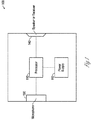
- FIG. 1 shows a block diagram of a hearing assistance device 100 according to one embodiment of the present subject matter.
- the hearing assistance device 100 includes hearing assistance electronics such as a processor 110 and at least one power supply 112.
- the processor 110 is a digital signal processor (DSP).
- the processor 110 is a microprocessor.
- the processor 110 is a microcontroller.
- the processor 110 is a combination of components. It is understood that in various embodiments, the processor 110 can be realized in a configuration of hardware or firmware, or a combination of both.
- the processor 110 is programmed to provide different processing functions depending on the signals sensed from the microphone 130.
- microphone 130 is configured to provide signals to the processor 110 which are processed and played to the wearer with speaker 140 (also known as a "receiver" in the hearing aid art).
- signals from a number of different signal sources can be detected using the teachings provided herein, such as audio information from a FM radio receiver, signals from a BLUETOOTH or other wireless receiver, signals from a magnetic induction source, signals from a wired audio connection, signals from a cellular phone, or signals from any other signal source.
- the present subject matter overcomes several problems encountered in assembling hearing assistance devices and their subcomponents.
- One of these problems is the time consuming, messy process of hand assembly and soldering.
- Another problem overcome by the present subject matter is the lengthy design time of each hearing aid circuit.
- the overall cost of materials, such as high density flex is reduced by the present subject matter.
- each limb of the circuit must be bent down and connected to another component.
- the connection is currently made by direct soldering, such as to a battery contact, or a wire must be soldered to the flexible circuit pad and then run to a second component, such as a push button or microphone.
- a second component such as a push button or microphone.
- soldering wire connections is hand soldering, and this process alone contributes significantly to the time required to make a custom hearing assistance product.
- the use of heat in the soldering process can cause component and circuit damage both during assembly and repair.
- the current method of using wires and soldering for hearing assistance device component interconnects consumes labor, time, additional parts (wires and additional subassemblies), additional parts cost, additional connection points and increased system volume. It also provides a difficult and messy repair process. Furthermore, the wires must be placed over the spine, taking up valuable space, and can be pulled or broken during the process.
- the present subject matter provides a hearing aid circuit and body that can be assembled without the need for solder or conductive epoxy.
- the present subject matter is unique in that it provides a method of assembling a hearing aid circuit to the spine and other components without the need of solder or conductive epoxy by utilizing a high density flexible circuit without wires in combination with a low density MID spine or housing, in various embodiments.
- Various embodiments of the present subject matter include a solderless microphone connection, solderless DSP module connection, solderless integration of a receiver jack, and solderless integrated programming interface.
- the present subject matter improves upon previous solutions because it does not require the addition of more wires or flexible circuit limbs.
- the method of the present subject matter leads to higher yields of hearing aid components since they are not subjected to soldering temperatures. Additionally, the design time and effort associated with developing new hearing aids is reduced, making assembly and repair substantially easier and quicker, and eliminating the need for circuit limbs leading to more circuits per panel.
- the present subject matter includes four types of solderless assembly connection.
- the connections are made via direct compression where the MID conductors form a connection with the flex without intermediary materials such as solder or conductive epoxy.
- the drawings illustrate a custom hearing aid application, but one of skill in the art would understand that the present subject matter is equally applicable to other types of hearing aids, such as those with a standard spine.
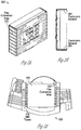
- FIGS. 2A-2B illustrate views of a flexible circuit module for a hearing assistance device, according to various embodiments of the present subject matter.
- a DSP module 200 includes an integrated flex connection area 202 having exposed traces.
- the exposed traces include Nickel Gold plating, in an embodiment. Other types of traces can be used without departing from the scope of the present subject matter.
- the traces are locate on the edges of the module, in various embodiments.
- An elastomeric material 204 is located between the flex and the module sides in various embodiments, providing pressure to ensure proper connections.
- FIGS. 3A-3C illustrate views of a MID housing 300 including conductive surface traces for a hearing assistance device, according to various embodiments of the present subject matter.
- the electrical connection with the flex connection area 302 is made with plastic fingers with traces 306 that have been processed using LDS or other three-dimensional (3D) molded interconnect device (MID) technologies to provide both the connection point as well as interconnection to other components, according to various embodiments.
- the elastomeric material 204 located between the flex and the module sides provides pressure to ensure proper connections, in various embodiments.
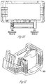
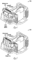
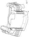
- FIGS. 4-5 illustrate views of a MID housing 300 including a microphone connection for a hearing assistance device, according to various embodiments of the present subject matter.
- a connection to a microphone 410 is made directly to the microphone pads.
- An LDS or other 3D MID technology is used to create metallized contacts 406 that can also function as interconnects to other components, in various embodiments.
- the contacts 406 are integral to the polymer contact fingers which provide one side of the connection.
- a retention band 412 of irradiated polymer (heat shrink) is applied over the microphone and fingers and heat applied to provide compression, in an embodiment.
- the retention is provided using a metal clip 514. Other retention mechanisms are possible without departing from the scope of the present subject matter.
- FIGS. 6-7 illustrate views of a MID housing including programming connections for a hearing assistance device, according to various embodiments of the present subject matter.
- program connections are made using LDS or other 3D MID technologies to create metallized connection contacts 620 that can also function as interconnects to other components.
- the MID housing accepts a programming strip 622, in an embodiment.
- the connection contacts 620 are integral to the MID housing 300, in various embodiments.
- a battery drawer 730 has cam action that provides compression to ensure a proper connection, according to various embodiments.
- SLA stereolithography
- FIGS. 8-10 illustrate views of a MID housing 300 including receiver connections for a hearing assistance device, according to various embodiments of the present subject matter.
- a microphone and a receiver To acoustically isolate a microphone and a receiver, no rigid connections are made to the receiver, in various embodiments. Flexible wires can be used and twisted to afford electromagnetic interference (EMI) protection as well, in various embodiments.
- EMI electromagnetic interference
- LDS is used to provide a receptacle (via) 802.
- the receptacle 802 is lasered at the same time as a traces pattern.
- the receptacle 802 and custom plug 904 are smaller than currently available receiver connections.
- TWI pins 1006 are used with a custom mold to create a jack/connector, in various embodiments.
- the TWI plug includes wires 1002 to the receiver and a molded grip 1004, in various embodiments.
- Other direct insertion mechanisms are possible without departing from the scope of the present subject matter.
- the present subject matter provides for specific connection schemes for the UCM, components and devices to solderlessly connect to a unifying LDS structure.
- a system that incorporates this connector as well as solderless microphone, programming and accessory connections is provided.
- the present subject matter has application for both Standard and Custom hearing aids, and is superior to previous solutions in that it decreases the number of heat cycles, touch points and increases the ability to reuse more components.
- the present subject matter provides an injection molded plastic structure made with an LDS capable plastic. In various embodiments, it is included in an area of a larger part and the entire part is LDS capable.
- the UCM includes a ball grid array (BGA) format, in an embodiment.
- BGA ball grid array
- the UCM is reflowed to a simple 2 layer flex that is long enough to wrap up both sides of the UCM and partially across the back, in an embodiment.
- the flex along the sides and back has a specified thickness of pressure sensitive adhesive (0.005 thick in an embodiment) applied so that it holds the flex to the sides and back.
- the flex along the sides is designed to provide exposed connective traces that are finished with a corrosion resistant finish similar to standard PCB pad finishes, in various embodiments.
- the UCM with flex is inserted into the LDS structure, and the LDS structure is designed to have conductive pressure points that align with conductive traces on the UCM flex circuit, in various embodiments.
- the LDS conductive traces also have a corrosion resistant finish, in an embodiment.
- the design of the LDS structure also provides a compressive force on the UCM with flex, in various embodiments. Additional retention features can be incorporated as needed.
- FIGS. 11 and 12 show an example in a standard product application of the present subject matter, showing an LDS structure 1100 and a UCM 1200.
- FIGS. 13 and 14 show an embodiment of a custom application.
- This subject matter can be used as a means of connection without solder of the UCM.
- the connections made by the LDS structure to other solderless connection structures for microphone, six pin jack, programming, TC, switches, etc. can be used.
- the present subject matter provides for the ability to replace or salvage the UCM. In the case of a defective UCM, the time to replace would only be a fraction of the time that would be need to rewire as in the case of a custom repair.
- the UCM can be removed without damage, in various embodiments.
- solderless connection to the UCM in standard products provides for the replacement of the UCM rather than having to replace the entire electronics system (the radio section and the entire high density flex, SMT switches, program jack etc.).
- the assembly time and component damage can be greatly reduced.
- the present subject matter provides for recovering and replacing of most the higher cost components possible without unnecessary damage or time required.
- the present subject matter can be used for standard fit as well as custom hearing aids, in various embodiments. Modules can be used in place of or in combination with flexible circuits, according to various embodiments. Benefits of the present subject matter include substantial assembly time and cost savings. Furthermore, the use of a common flexible circuit board for a variety of spine designs leads to less design time required for each hearing aid circuit style. The elimination of soldered wires as well as flexible circuit limbs leads to smaller hearing aids, in various embodiments.
- the wireless communications can include standard or nonstandard communications.
- standard wireless communications include link protocols including, but not limited to, BluetoothTM, IEEE 802.11(wireless LANs), 802.15 (WPANs), 802.16 (WiMAX), cellular protocols including, but not limited to CDMA and GSM, ZigBee, and ultra-wideband (UWB) technologies.
- Such protocols support radio frequency communications and some support infrared communications.
- the present system is demonstrated as a radio system, it is possible that other forms of wireless communications can be used such as ultrasonic, optical, infrared, and others.
- the standards which can be used include past and present standards. It is also contemplated that future versions of these standards and new future standards may be employed without departing from the scope of the present subject matter.
- the wireless communications support a connection from other devices.
- Such connections include, but are not limited to, one or more mono or stereo connections or digital connections having link protocols including, but not limited to 802.3 (Ethernet), 802.4, 802.5, USB, SPI, PCM, ATM, Fibre-channel, Firewire or 1394, InfiniBand, or a native streaming interface.
- link protocols including, but not limited to 802.3 (Ethernet), 802.4, 802.5, USB, SPI, PCM, ATM, Fibre-channel, Firewire or 1394, InfiniBand, or a native streaming interface.
- such connections include all past and present link protocols. It is also contemplated that future versions of these protocols and new future standards may be employed without departing from the scope of the present subject matter.
- Hearing assistance devices typically include an enclosure or housing, a microphone, hearing assistance device electronics including processing electronics, and a speaker or receiver. It is understood that in various embodiments the receiver is optional.
- Antenna configurations may vary and may be included within an enclosure for the electronics or be external to an enclosure for the electronics. Thus, the examples set forth herein are intended to be demonstrative and not a limiting or exhaustive depiction of variations.
- any hearing assistance device may be used without departing from the scope and the devices depicted in the figures are intended to demonstrate the subject matter, but not in a limited, exhaustive, or exclusive sense. It is also understood that the present subject matter can be used with a device designed for use in the right ear or the left ear or both ears of the user.
- the hearing aids referenced in this patent application include a processor.
- the processor may be a digital signal processor (DSP), microprocessor, microcontroller, other digital logic, a separate analog and separate digital chip, or combinations thereof.
- DSP digital signal processor
- the processing of signals referenced in this application can be performed using the processor. Processing may be done in the digital domain, the analog domain, or combinations thereof. Processing may be done using subband processing techniques. Processing may be done with frequency domain or time domain approaches. Some processing may involve both frequency and time domain aspects. For brevity, in some examples drawings may omit certain blocks that perform frequency synthesis, frequency analysis, analog-to-digital conversion, digital-to-analog conversion, amplification, audio decoding, and certain types of filtering and processing.
- the processor is adapted to perform instructions stored in memory which may or may not be explicitly shown.
- Various types of memory may be used, including volatile and nonvolatile forms of memory.
- instructions are performed by the processor to perform a number of signal processing tasks.
- analog components are in communication with the processor to perform signal tasks, such as microphone reception, or receiver sound embodiments (i.e., in applications where such transducers are used).
- signal tasks such as microphone reception, or receiver sound embodiments (i.e., in applications where such transducers are used).
- different realizations of the block diagrams, circuits, and processes set forth herein may occur without departing from the scope of the present subject matter.
- hearing assistance devices including hearing aids, including but not limited to, behind-the-ear (BTE), in-the-ear (ITE), in-the-canal (ITC), receiver-in-canal (RIC), completely-in-the-canal (CIC) or invisible-in-canal (IIC) type hearing aids.
- BTE behind-the-ear
- ITE in-the-ear
- ITC in-the-canal
- RIC receiver-in-canal
- CIC completely-in-the-canal
- IIC invisible-in-canal
- hearing assistance devices including but not limited to, behind-the-ear (BTE), in-the-ear (ITE), in-the-canal (ITC), receiver-in-canal (RIC), completely-in-the-canal (CIC) or invisible-in-canal (IIC) type hearing aids.
- BTE behind-the-ear
- ITE in-the-ear
- ITC in-the-canal
- RIC receiver-in-canal
- the present subject matter can also be used in hearing assistance devices generally, such as cochlear implant type hearing devices and such as deep insertion devices having a transducer, such as a receiver or microphone, whether custom fitted, standard, open fitted or occlusive fitted. It is understood that other hearing assistance devices not expressly stated herein may be used in conjunction with the present subject matter.
- the present subject matter can be used in other settings in addition to hearing assistance. Examples include, but are not limited to, telephone applications where noise-corrupted speech is introduced, and streaming audio for ear pieces or headphones.
Landscapes
- Engineering & Computer Science (AREA)
- Manufacturing & Machinery (AREA)
- Health & Medical Sciences (AREA)
- General Health & Medical Sciences (AREA)
- Neurosurgery (AREA)
- Otolaryngology (AREA)
- Physics & Mathematics (AREA)
- Acoustics & Sound (AREA)
- Signal Processing (AREA)
- Details Of Audible-Bandwidth Transducers (AREA)
Applications Claiming Priority (1)
| Application Number | Priority Date | Filing Date | Title |
|---|---|---|---|
| US14/692,849 US9906879B2 (en) | 2013-11-27 | 2015-04-22 | Solderless module connector for a hearing assistance device assembly |
Publications (2)
| Publication Number | Publication Date |
|---|---|
| EP3086576A1 true EP3086576A1 (de) | 2016-10-26 |
| EP3086576B1 EP3086576B1 (de) | 2021-09-01 |
Family
ID=55952960
Family Applications (1)
| Application Number | Title | Priority Date | Filing Date |
|---|---|---|---|
| EP16166704.3A Active EP3086576B1 (de) | 2015-04-22 | 2016-04-22 | Lötfreier modulverbinder für eine hörhilfevorrichtung |
Country Status (1)
| Country | Link |
|---|---|
| EP (1) | EP3086576B1 (de) |
Cited By (1)
| Publication number | Priority date | Publication date | Assignee | Title |
|---|---|---|---|---|
| US20230061252A1 (en) * | 2021-08-30 | 2023-03-02 | Japan Aviation Electronics Industry, Limited | Connector |
Citations (3)
| Publication number | Priority date | Publication date | Assignee | Title |
|---|---|---|---|---|
| US4116517A (en) * | 1976-04-15 | 1978-09-26 | International Telephone And Telegraph Corporation | Flexible printed circuit and electrical connection therefor |
| EP2063694A1 (de) * | 2006-09-29 | 2009-05-27 | Panasonic Electric Works Co., Ltd | Audioausgabeeinrichtung |
| EP2879407A1 (de) * | 2013-11-27 | 2015-06-03 | Starkey Laboratories, Inc. | Lötfreie Hörhilfevorrichtungsanordnung und Verfahren |
Family Cites Families (1)
| Publication number | Priority date | Publication date | Assignee | Title |
|---|---|---|---|---|
| JP3153682B2 (ja) * | 1993-08-26 | 2001-04-09 | 松下電工株式会社 | 回路板の製造方法 |
-
2016
- 2016-04-22 EP EP16166704.3A patent/EP3086576B1/de active Active
Patent Citations (3)
| Publication number | Priority date | Publication date | Assignee | Title |
|---|---|---|---|---|
| US4116517A (en) * | 1976-04-15 | 1978-09-26 | International Telephone And Telegraph Corporation | Flexible printed circuit and electrical connection therefor |
| EP2063694A1 (de) * | 2006-09-29 | 2009-05-27 | Panasonic Electric Works Co., Ltd | Audioausgabeeinrichtung |
| EP2879407A1 (de) * | 2013-11-27 | 2015-06-03 | Starkey Laboratories, Inc. | Lötfreie Hörhilfevorrichtungsanordnung und Verfahren |
Non-Patent Citations (1)
| Title |
|---|
| ANONYMOUS: "Molded interconnect device - Wikipedia, the free encyclopedia", 9 February 2015 (2015-02-09), XP055290225, Retrieved from the Internet <URL:https://en.wikipedia.org/w/index.php?title=Molded_interconnect_device&oldid=646412742> [retrieved on 20160721] * |
Cited By (2)
| Publication number | Priority date | Publication date | Assignee | Title |
|---|---|---|---|---|
| US20230061252A1 (en) * | 2021-08-30 | 2023-03-02 | Japan Aviation Electronics Industry, Limited | Connector |
| US12237597B2 (en) * | 2021-08-30 | 2025-02-25 | Japan Aviation Electronics Industry, Limited | Connector |
Also Published As
| Publication number | Publication date |
|---|---|
| EP3086576B1 (de) | 2021-09-01 |
Similar Documents
| Publication | Publication Date | Title |
|---|---|---|
| US9906879B2 (en) | Solderless module connector for a hearing assistance device assembly | |
| EP2879407B1 (de) | Lötfreie Hörhilfevorrichtungsanordnung und Verfahren | |
| US12022263B2 (en) | Radio frequency antenna for an in-the-ear hearing device | |
| US9374650B2 (en) | System and method for embedding conductive traces into hearing assistance device housings | |
| US9474154B2 (en) | Reflow solderable flexible circuit board — to — flexible circuit board connector reinforcement | |
| US9408004B2 (en) | Flex connector for a hearing assistance device | |
| EP3116240B2 (de) | Hörgerät mit abnehmbarer lautsprechereinheit | |
| US9049526B2 (en) | Compact programming block connector for hearing assistance devices | |
| US20140328507A1 (en) | Increasing antenna performance for wireless hearing assistance devices | |
| JP2021521695A5 (de) | ||
| EP3188509A1 (de) | Ohrhaken und schallröhrenantennen für hörhilfevorrichtung | |
| EP2424275A1 (de) | Angepasste Hörvorrichtung zur Herstellung einer elektrischen Verbindung zu einem externen Gerät mittels einer oder mehrerer elektrisch leitender Komponenten der Hörvorrichtung | |
| CN114979879A (zh) | 包括电池模块的听力设备和制造听力设备电池模块的方法 | |
| EP3086576B1 (de) | Lötfreier modulverbinder für eine hörhilfevorrichtung | |
| DK2992688T3 (en) | IMPROVING ANTENNA PERFORMANCE FOR WIRELESS HEARINGS | |
| EP2942979A1 (de) | Erhöhung der antennenleistung für drahtlose hörhilfegeräte | |
| US20180317032A1 (en) | Method for producing a supporting frame of a hearing aid, supporting frame and hearing aid | |
| EP4272460B1 (de) | Hörgerät mit einem haltemechanismus für ein externes multifunktionskabel und verfahren zur montage des genannten hörgeräts. | |
| US8548183B2 (en) | Hearing device with individually aligned electronic component and production method |
Legal Events
| Date | Code | Title | Description |
|---|---|---|---|
| PUAI | Public reference made under article 153(3) epc to a published international application that has entered the european phase |
Free format text: ORIGINAL CODE: 0009012 |
|
| AK | Designated contracting states |
Kind code of ref document: A1 Designated state(s): AL AT BE BG CH CY CZ DE DK EE ES FI FR GB GR HR HU IE IS IT LI LT LU LV MC MK MT NL NO PL PT RO RS SE SI SK SM TR |
|
| AX | Request for extension of the european patent |
Extension state: BA ME |
|
| STAA | Information on the status of an ep patent application or granted ep patent |
Free format text: STATUS: THE APPLICATION HAS BEEN PUBLISHED |
|
| 17P | Request for examination filed |
Effective date: 20170426 |
|
| RBV | Designated contracting states (corrected) |
Designated state(s): AL AT BE BG CH CY CZ DE DK EE ES FI FR GB GR HR HU IE IS IT LI LT LU LV MC MK MT NL NO PL PT RO RS SE SI SK SM TR |
|
| STAA | Information on the status of an ep patent application or granted ep patent |
Free format text: STATUS: REQUEST FOR EXAMINATION WAS MADE |
|
| STAA | Information on the status of an ep patent application or granted ep patent |
Free format text: STATUS: EXAMINATION IS IN PROGRESS |
|
| 17Q | First examination report despatched |
Effective date: 20190401 |
|
| RAP1 | Party data changed (applicant data changed or rights of an application transferred) |
Owner name: STARKEY LABORATORIES, INC. |
|
| RIN1 | Information on inventor provided before grant (corrected) |
Inventor name: DZARNOSKI, JOHN Inventor name: PRCHAL, DAVID Inventor name: JOHANSSON, SUSIE |
|
| GRAP | Despatch of communication of intention to grant a patent |
Free format text: ORIGINAL CODE: EPIDOSNIGR1 |
|
| STAA | Information on the status of an ep patent application or granted ep patent |
Free format text: STATUS: GRANT OF PATENT IS INTENDED |
|
| RIC1 | Information provided on ipc code assigned before grant |
Ipc: H01R 13/24 20060101ALN20210322BHEP Ipc: H01R 12/71 20110101ALN20210322BHEP Ipc: H01R 12/70 20110101ALI20210322BHEP Ipc: H04R 25/00 20060101AFI20210322BHEP |
|
| INTG | Intention to grant announced |
Effective date: 20210413 |
|
| GRAS | Grant fee paid |
Free format text: ORIGINAL CODE: EPIDOSNIGR3 |
|
| GRAA | (expected) grant |
Free format text: ORIGINAL CODE: 0009210 |
|
| STAA | Information on the status of an ep patent application or granted ep patent |
Free format text: STATUS: THE PATENT HAS BEEN GRANTED |
|
| AK | Designated contracting states |
Kind code of ref document: B1 Designated state(s): AL AT BE BG CH CY CZ DE DK EE ES FI FR GB GR HR HU IE IS IT LI LT LU LV MC MK MT NL NO PL PT RO RS SE SI SK SM TR |
|
| REG | Reference to a national code |
Ref country code: GB Ref legal event code: FG4D |
|
| REG | Reference to a national code |
Ref country code: CH Ref legal event code: EP Ref country code: AT Ref legal event code: REF Ref document number: 1427529 Country of ref document: AT Kind code of ref document: T Effective date: 20210915 |
|
| REG | Reference to a national code |
Ref country code: DE Ref legal event code: R096 Ref document number: 602016062961 Country of ref document: DE |
|
| REG | Reference to a national code |
Ref country code: IE Ref legal event code: FG4D |
|
| REG | Reference to a national code |
Ref country code: LT Ref legal event code: MG9D |
|
| REG | Reference to a national code |
Ref country code: NL Ref legal event code: MP Effective date: 20210901 |
|
| PG25 | Lapsed in a contracting state [announced via postgrant information from national office to epo] |
Ref country code: HR Free format text: LAPSE BECAUSE OF FAILURE TO SUBMIT A TRANSLATION OF THE DESCRIPTION OR TO PAY THE FEE WITHIN THE PRESCRIBED TIME-LIMIT Effective date: 20210901 Ref country code: RS Free format text: LAPSE BECAUSE OF FAILURE TO SUBMIT A TRANSLATION OF THE DESCRIPTION OR TO PAY THE FEE WITHIN THE PRESCRIBED TIME-LIMIT Effective date: 20210901 Ref country code: SE Free format text: LAPSE BECAUSE OF FAILURE TO SUBMIT A TRANSLATION OF THE DESCRIPTION OR TO PAY THE FEE WITHIN THE PRESCRIBED TIME-LIMIT Effective date: 20210901 Ref country code: LT Free format text: LAPSE BECAUSE OF FAILURE TO SUBMIT A TRANSLATION OF THE DESCRIPTION OR TO PAY THE FEE WITHIN THE PRESCRIBED TIME-LIMIT Effective date: 20210901 Ref country code: BG Free format text: LAPSE BECAUSE OF FAILURE TO SUBMIT A TRANSLATION OF THE DESCRIPTION OR TO PAY THE FEE WITHIN THE PRESCRIBED TIME-LIMIT Effective date: 20211201 Ref country code: NO Free format text: LAPSE BECAUSE OF FAILURE TO SUBMIT A TRANSLATION OF THE DESCRIPTION OR TO PAY THE FEE WITHIN THE PRESCRIBED TIME-LIMIT Effective date: 20211201 Ref country code: ES Free format text: LAPSE BECAUSE OF FAILURE TO SUBMIT A TRANSLATION OF THE DESCRIPTION OR TO PAY THE FEE WITHIN THE PRESCRIBED TIME-LIMIT Effective date: 20210901 Ref country code: FI Free format text: LAPSE BECAUSE OF FAILURE TO SUBMIT A TRANSLATION OF THE DESCRIPTION OR TO PAY THE FEE WITHIN THE PRESCRIBED TIME-LIMIT Effective date: 20210901 |
|
| REG | Reference to a national code |
Ref country code: AT Ref legal event code: MK05 Ref document number: 1427529 Country of ref document: AT Kind code of ref document: T Effective date: 20210901 |
|
| PG25 | Lapsed in a contracting state [announced via postgrant information from national office to epo] |
Ref country code: PL Free format text: LAPSE BECAUSE OF FAILURE TO SUBMIT A TRANSLATION OF THE DESCRIPTION OR TO PAY THE FEE WITHIN THE PRESCRIBED TIME-LIMIT Effective date: 20210901 Ref country code: LV Free format text: LAPSE BECAUSE OF FAILURE TO SUBMIT A TRANSLATION OF THE DESCRIPTION OR TO PAY THE FEE WITHIN THE PRESCRIBED TIME-LIMIT Effective date: 20210901 Ref country code: GR Free format text: LAPSE BECAUSE OF FAILURE TO SUBMIT A TRANSLATION OF THE DESCRIPTION OR TO PAY THE FEE WITHIN THE PRESCRIBED TIME-LIMIT Effective date: 20211202 |
|
| PG25 | Lapsed in a contracting state [announced via postgrant information from national office to epo] |
Ref country code: AT Free format text: LAPSE BECAUSE OF FAILURE TO SUBMIT A TRANSLATION OF THE DESCRIPTION OR TO PAY THE FEE WITHIN THE PRESCRIBED TIME-LIMIT Effective date: 20210901 |
|
| PGFP | Annual fee paid to national office [announced via postgrant information from national office to epo] |
Ref country code: GB Payment date: 20220308 Year of fee payment: 7 |
|
| PG25 | Lapsed in a contracting state [announced via postgrant information from national office to epo] |
Ref country code: IS Free format text: LAPSE BECAUSE OF FAILURE TO SUBMIT A TRANSLATION OF THE DESCRIPTION OR TO PAY THE FEE WITHIN THE PRESCRIBED TIME-LIMIT Effective date: 20220101 Ref country code: SM Free format text: LAPSE BECAUSE OF FAILURE TO SUBMIT A TRANSLATION OF THE DESCRIPTION OR TO PAY THE FEE WITHIN THE PRESCRIBED TIME-LIMIT Effective date: 20210901 Ref country code: SK Free format text: LAPSE BECAUSE OF FAILURE TO SUBMIT A TRANSLATION OF THE DESCRIPTION OR TO PAY THE FEE WITHIN THE PRESCRIBED TIME-LIMIT Effective date: 20210901 Ref country code: RO Free format text: LAPSE BECAUSE OF FAILURE TO SUBMIT A TRANSLATION OF THE DESCRIPTION OR TO PAY THE FEE WITHIN THE PRESCRIBED TIME-LIMIT Effective date: 20210901 Ref country code: PT Free format text: LAPSE BECAUSE OF FAILURE TO SUBMIT A TRANSLATION OF THE DESCRIPTION OR TO PAY THE FEE WITHIN THE PRESCRIBED TIME-LIMIT Effective date: 20220103 Ref country code: NL Free format text: LAPSE BECAUSE OF FAILURE TO SUBMIT A TRANSLATION OF THE DESCRIPTION OR TO PAY THE FEE WITHIN THE PRESCRIBED TIME-LIMIT Effective date: 20210901 Ref country code: EE Free format text: LAPSE BECAUSE OF FAILURE TO SUBMIT A TRANSLATION OF THE DESCRIPTION OR TO PAY THE FEE WITHIN THE PRESCRIBED TIME-LIMIT Effective date: 20210901 Ref country code: CZ Free format text: LAPSE BECAUSE OF FAILURE TO SUBMIT A TRANSLATION OF THE DESCRIPTION OR TO PAY THE FEE WITHIN THE PRESCRIBED TIME-LIMIT Effective date: 20210901 Ref country code: AL Free format text: LAPSE BECAUSE OF FAILURE TO SUBMIT A TRANSLATION OF THE DESCRIPTION OR TO PAY THE FEE WITHIN THE PRESCRIBED TIME-LIMIT Effective date: 20210901 |
|
| REG | Reference to a national code |
Ref country code: DE Ref legal event code: R097 Ref document number: 602016062961 Country of ref document: DE |
|
| PLBE | No opposition filed within time limit |
Free format text: ORIGINAL CODE: 0009261 |
|
| STAA | Information on the status of an ep patent application or granted ep patent |
Free format text: STATUS: NO OPPOSITION FILED WITHIN TIME LIMIT |
|
| PG25 | Lapsed in a contracting state [announced via postgrant information from national office to epo] |
Ref country code: IT Free format text: LAPSE BECAUSE OF FAILURE TO SUBMIT A TRANSLATION OF THE DESCRIPTION OR TO PAY THE FEE WITHIN THE PRESCRIBED TIME-LIMIT Effective date: 20210901 Ref country code: DK Free format text: LAPSE BECAUSE OF FAILURE TO SUBMIT A TRANSLATION OF THE DESCRIPTION OR TO PAY THE FEE WITHIN THE PRESCRIBED TIME-LIMIT Effective date: 20210901 |
|
| 26N | No opposition filed |
Effective date: 20220602 |
|
| PG25 | Lapsed in a contracting state [announced via postgrant information from national office to epo] |
Ref country code: SI Free format text: LAPSE BECAUSE OF FAILURE TO SUBMIT A TRANSLATION OF THE DESCRIPTION OR TO PAY THE FEE WITHIN THE PRESCRIBED TIME-LIMIT Effective date: 20210901 |
|
| REG | Reference to a national code |
Ref country code: CH Ref legal event code: PL |
|
| REG | Reference to a national code |
Ref country code: BE Ref legal event code: MM Effective date: 20220430 |
|
| PG25 | Lapsed in a contracting state [announced via postgrant information from national office to epo] |
Ref country code: MC Free format text: LAPSE BECAUSE OF FAILURE TO SUBMIT A TRANSLATION OF THE DESCRIPTION OR TO PAY THE FEE WITHIN THE PRESCRIBED TIME-LIMIT Effective date: 20210901 Ref country code: LU Free format text: LAPSE BECAUSE OF NON-PAYMENT OF DUE FEES Effective date: 20220422 Ref country code: LI Free format text: LAPSE BECAUSE OF NON-PAYMENT OF DUE FEES Effective date: 20220430 Ref country code: CH Free format text: LAPSE BECAUSE OF NON-PAYMENT OF DUE FEES Effective date: 20220430 |
|
| PG25 | Lapsed in a contracting state [announced via postgrant information from national office to epo] |
Ref country code: BE Free format text: LAPSE BECAUSE OF NON-PAYMENT OF DUE FEES Effective date: 20220430 |
|
| PG25 | Lapsed in a contracting state [announced via postgrant information from national office to epo] |
Ref country code: IE Free format text: LAPSE BECAUSE OF NON-PAYMENT OF DUE FEES Effective date: 20220422 |
|
| P01 | Opt-out of the competence of the unified patent court (upc) registered |
Effective date: 20230624 |
|
| GBPC | Gb: european patent ceased through non-payment of renewal fee |
Effective date: 20230422 |
|
| PG25 | Lapsed in a contracting state [announced via postgrant information from national office to epo] |
Ref country code: GB Free format text: LAPSE BECAUSE OF NON-PAYMENT OF DUE FEES Effective date: 20230422 |
|
| PG25 | Lapsed in a contracting state [announced via postgrant information from national office to epo] |
Ref country code: GB Free format text: LAPSE BECAUSE OF NON-PAYMENT OF DUE FEES Effective date: 20230422 |
|
| PG25 | Lapsed in a contracting state [announced via postgrant information from national office to epo] |
Ref country code: HU Free format text: LAPSE BECAUSE OF FAILURE TO SUBMIT A TRANSLATION OF THE DESCRIPTION OR TO PAY THE FEE WITHIN THE PRESCRIBED TIME-LIMIT; INVALID AB INITIO Effective date: 20160422 |
|
| PG25 | Lapsed in a contracting state [announced via postgrant information from national office to epo] |
Ref country code: MK Free format text: LAPSE BECAUSE OF FAILURE TO SUBMIT A TRANSLATION OF THE DESCRIPTION OR TO PAY THE FEE WITHIN THE PRESCRIBED TIME-LIMIT Effective date: 20210901 Ref country code: CY Free format text: LAPSE BECAUSE OF FAILURE TO SUBMIT A TRANSLATION OF THE DESCRIPTION OR TO PAY THE FEE WITHIN THE PRESCRIBED TIME-LIMIT Effective date: 20210901 |
|
| PG25 | Lapsed in a contracting state [announced via postgrant information from national office to epo] |
Ref country code: MT Free format text: LAPSE BECAUSE OF FAILURE TO SUBMIT A TRANSLATION OF THE DESCRIPTION OR TO PAY THE FEE WITHIN THE PRESCRIBED TIME-LIMIT Effective date: 20210901 |
|
| PGFP | Annual fee paid to national office [announced via postgrant information from national office to epo] |
Ref country code: DE Payment date: 20250313 Year of fee payment: 10 |
|
| PG25 | Lapsed in a contracting state [announced via postgrant information from national office to epo] |
Ref country code: TR Free format text: LAPSE BECAUSE OF FAILURE TO SUBMIT A TRANSLATION OF THE DESCRIPTION OR TO PAY THE FEE WITHIN THE PRESCRIBED TIME-LIMIT Effective date: 20210901 |
|
| PGFP | Annual fee paid to national office [announced via postgrant information from national office to epo] |
Ref country code: FR Payment date: 20260311 Year of fee payment: 11 |