EP3086623B1 - Vorrichtung zum ersetzen von einem oder mehreren paaren von linearen, in einer leuchte installierten und mit einem konventionellen magnetischen steuerungsgetriebe verdrahteten leuchtstoffröhren und lampe damit - Google Patents
Vorrichtung zum ersetzen von einem oder mehreren paaren von linearen, in einer leuchte installierten und mit einem konventionellen magnetischen steuerungsgetriebe verdrahteten leuchtstoffröhren und lampe damit Download PDFInfo
- Publication number
- EP3086623B1 EP3086623B1 EP15164464.8A EP15164464A EP3086623B1 EP 3086623 B1 EP3086623 B1 EP 3086623B1 EP 15164464 A EP15164464 A EP 15164464A EP 3086623 B1 EP3086623 B1 EP 3086623B1
- Authority
- EP
- European Patent Office
- Prior art keywords
- terminals
- input
- output
- filter
- terminal
- Prior art date
- Legal status (The legal status is an assumption and is not a legal conclusion. Google has not performed a legal analysis and makes no representation as to the accuracy of the status listed.)
- Not-in-force
Links
- 239000003990 capacitor Substances 0.000 claims description 14
- 239000007858 starting material Substances 0.000 claims description 7
- 239000011521 glass Substances 0.000 claims description 2
- 239000000463 material Substances 0.000 claims description 2
- 230000001105 regulatory effect Effects 0.000 claims 2
- 238000010586 diagram Methods 0.000 description 9
- 238000009434 installation Methods 0.000 description 5
- 238000009420 retrofitting Methods 0.000 description 3
- 230000004048 modification Effects 0.000 description 2
- 238000012986 modification Methods 0.000 description 2
- 238000009429 electrical wiring Methods 0.000 description 1
- 238000005265 energy consumption Methods 0.000 description 1
- 230000004907 flux Effects 0.000 description 1
- 238000002955 isolation Methods 0.000 description 1
- 238000009877 rendering Methods 0.000 description 1
- 230000002441 reversible effect Effects 0.000 description 1
Images


Classifications
-
- H—ELECTRICITY
- H05—ELECTRIC TECHNIQUES NOT OTHERWISE PROVIDED FOR
- H05B—ELECTRIC HEATING; ELECTRIC LIGHT SOURCES NOT OTHERWISE PROVIDED FOR; CIRCUIT ARRANGEMENTS FOR ELECTRIC LIGHT SOURCES, IN GENERAL
- H05B45/00—Circuit arrangements for operating light-emitting diodes [LED]
- H05B45/30—Driver circuits
- H05B45/37—Converter circuits
- H05B45/3725—Switched mode power supply [SMPS]
-
- H—ELECTRICITY
- H05—ELECTRIC TECHNIQUES NOT OTHERWISE PROVIDED FOR
- H05B—ELECTRIC HEATING; ELECTRIC LIGHT SOURCES NOT OTHERWISE PROVIDED FOR; CIRCUIT ARRANGEMENTS FOR ELECTRIC LIGHT SOURCES, IN GENERAL
- H05B45/00—Circuit arrangements for operating light-emitting diodes [LED]
- H05B45/30—Driver circuits
- H05B45/357—Driver circuits specially adapted for retrofit LED light sources
- H05B45/3578—Emulating the electrical or functional characteristics of discharge lamps
-
- Y—GENERAL TAGGING OF NEW TECHNOLOGICAL DEVELOPMENTS; GENERAL TAGGING OF CROSS-SECTIONAL TECHNOLOGIES SPANNING OVER SEVERAL SECTIONS OF THE IPC; TECHNICAL SUBJECTS COVERED BY FORMER USPC CROSS-REFERENCE ART COLLECTIONS [XRACs] AND DIGESTS
- Y02—TECHNOLOGIES OR APPLICATIONS FOR MITIGATION OR ADAPTATION AGAINST CLIMATE CHANGE
- Y02B—CLIMATE CHANGE MITIGATION TECHNOLOGIES RELATED TO BUILDINGS, e.g. HOUSING, HOUSE APPLIANCES OR RELATED END-USER APPLICATIONS
- Y02B20/00—Energy efficient lighting technologies, e.g. halogen lamps or gas discharge lamps
- Y02B20/30—Semiconductor lamps, e.g. solid state lamps [SSL] light emitting diodes [LED] or organic LED [OLED]
Definitions
- the present invention relates to the field of lighting systems and more specifically relates to a device for the replacement of one or more pairs of linear fluorescent tubes installed in a luminaire and wired with magnetic conventional control gear (C.C.G.).
- Existing linear fluorescent T8 lighting tubes for instance with a power rating of 18W, provided with G13 base and having a typical length of 600mm, can be accommodated both in fixtures comprising an electronic control gear and in luminaires with magnetic conventional control gear (C.C.G.).
- the fluorescent tubes can be connected each in series to a dedicated Electro Magnetic (E.M.) ballast for 18W, corresponding to a single C.C.G. wiring, or they can be connected in series to each other, in pairs, and, in turn, fed in series by a single dedicated E.M. ballast for instance rated for 36W ⁇ 40W, corresponding to a double C.C.G. wiring.
- E.M. Electro Magnetic
- LED lamps offer several advantages compared to conventional light sources, such as incandescent and fluorescent lamps. The most important are, among others, lower power consumption, higher luminous efficacy, high color rendering index and longer lifetime.
- LED tubes adapted to replace traditional fluorescent tubes.
- LED tubes offer an advantageous solution compared to traditional fluorescent tubes in terms of energy consumption (typically LED tubes consume half or less of the power of the fluorescent tubes of equal size, of equal base and of equal dimensions with respect to the fluorescent tubes they are intended to replace), although replacement of fluorescent tubes with LED tubes involves performance issues, in terms of luminous flux, and retrofitting cost issues that make existing LED tubes still far from being a complete and costless equivalent to fluorescent tubes.
- US patent application US2014035463A1 discloses an example of LED lamp provided with PWM control.
- the purpose of the present invention is therefore to introduce a device for the replacement of one or more pairs of linear fluorescent T8 tubes connected in series inside fixtures with conventional magnetic wiring with LED tubes.
- the proposed solution according to the present invention is adapted to work with common mains voltages, for instance 110 ⁇ 130 VAC or 220 ⁇ 240 VAC and 50 ⁇ 60 Hz frequency.
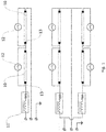
- FIG. 1 shows an example of state of the art wiring of fixtures comprising at least a pair of fluorescent tubes provided with conventional control gear and electromagnetic ballast.
- 18W fluorescent T8 tubes 10 are connected in series with double C.C.G. wiring, and an E.M. ballast 11 is, in turn, connected in series to the pair of tubes.
- the E.M. ballast has a power rating of 40 W.
- Each fluorescent tube 10 is ignited by a dedicated glow starter 12 connected in parallel with the tube 10, between pins of opposite side tube connectors 13.
- An additional power factor correction (P.F.C.) capacitor can be placed in parallel between the AC power supply terminals of the luminaire.
- P.F.C. additional power factor correction
- the present invention implemented as a LED tube replacement for fluorescent T8 tubes, can be used in luminaires with one or more pairs of fluorescent tubes 10 connected in series and powered by a series magnetic ballast 11 and two glow starters 12 (one for each fluorescent lamp) and possibly by a power factor correction capacitor placed in parallel between the terminals of the supply network of the luminaire.
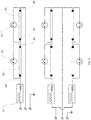
- each fluorescent tube 10 of Fig.1 has been replaced by the LED tube device 20 according to the present invention, no matter what orientation, while each glow starter of Fig.1 has been replaced by a jumper or by a fuse 21.
- said jumper and said fuse 21 can be provided in a container having the same size and pinout of traditional glow starters so that no modification to the layout of the fixture is needed when replacing the original fluorescent tube 10 with the LED tube device 20 according to the present invention.
- the P.F.C. capacitor between the AC power supply terminals of the luminaire is no longer needed.
- the generic block diagram of the LED tube 20 comprises: a LED driver 30, adapted to convert the input AC voltage and current into DC voltage and current to supply the load comprising a plurality of LEDs 31 suitably connected to each other, associated to a first and a second input DC terminals and preferably mounted on a LED board 32.
- the block diagram of the LED tube 20 according to the present invention is displayed, in figure 3 , within a tube provided with bi-pin connectors 33, preferably of G5 or G13 type, at the two ends, said tube being preferably similar, in shape and size, to fluorescent light type tubes.
- Each one of the input terminals of said LED driver 30 is connected to a different pin of one of said bi-pin connectors 33, the pins of the other bi-pin connector 33 being short circuited.
- the resistor R3 provides control and regulation of the output current.
- said input filter 42 comprises a capacitor C1 in parallel with a resistor R1, connected between one of said input terminals 45 and one of said output terminals 46 of said input filter 42.
- said output filter 44 comprises a capacitor C2 in parallel with a resistor R2, both connected between said input terminals 49 and said output terminals 50.
- R1, C1, R2 and C2 are chosen depending on the LED board that said LED driver is adapted to supply. Furthermore, the values of R1, C1, R2 and C2 may be chosen considering the series RL circuit equivalent to said series magnetic ballast pre-installed in the luminaire.
- Said series constant current regulator is adapted to control the output current of said LED driver and preferably it comprises an integrated circuit (I.C.) adapted to produce a constant current output, even in case of wide fluctuations in the supply voltage amplitude.
- I.C. integrated circuit
- the block diagram of a LED driver not covered by the claims comprising a switch mode power supply, said third preferred embodiment of said LED driver comprising:
- the DC/DC converter may comprise a switching stage, for instance a pulse width modulator (P.W.M.) stage, a high-frequency transformer or an inductor, depending on the isolated or non-isolated topology of the power supply, an output rectifier and an output filter, to provide the final DC output voltage and current.
- P.W.M. pulse width modulator
- a high-frequency transformer or an inductor depending on the isolated or non-isolated topology of the power supply
- an output rectifier and an output filter to provide the final DC output voltage and current.
- the DC/DC converter may be either "open-loop", so that it does not have a feedback circuit, or "closed-loop", so that a feedback circuit is present to monitor the output voltage and/or the output current and to compare them with a reference voltage and/or with a reference current.
- the DC/DC converter controller stage may contain an isolation device, such as an optoisolator to isolate said controller from the DC output.
- the device according to the present invention may be made in shape and size to be adapted to fit in a tube having the standard dimension of fluorescent tube lamps.
- Said tube having the standard dimension of fluorescent tube lamps can be made of glass or plastic or other materials and can be transparent or opaque.
- each fluorescent tube 10 of figure 1 has been replaced by the LED tube device 20 according to the present invention, no matter what orientation, while each glow starter 12 of figure 1 has been replaced by a jumper or a fuse 21.
- Said luminaire comprises:
Landscapes
- Circuit Arrangement For Electric Light Sources In General (AREA)
Claims (8)
- Beleuchtungsvorrichtung (20) für Stift-zu-Stift Austausch von geraden Leuchtröhren (10) in magnetischen Ballastbefestigungen, wobei die Beleuchtungsvorrichtung (20) aus Folgendem besteht:
einem Behälter mit zwei Enden, von denen jedes mit einem Stecker mit zwei Stiften (33) versehen ist, wobei der Behälter so ausgelegt ist, dass er Licht durchlässt, und zur Aufnahme von Folgendem ausgelegt ist:einer Vielzahl von LEDs (31), die an eine erste und eine zweite DC-Eingangsklemme angeschlossen sind;einem LED-Treiber (30), der aus Folgendem besteht:AC-Eingangsklemmen (40), die für den Anschluss mit den Klemmen eines der Stecker mit zwei Stiften (33) konfiguriert sind;DC-Ausgängklemmen (41), die an die erste und die zweite DC-Eingangklemme der Vielzahl von LEDs (31) anzuschließen sind;einem Eingangsstromfilter (42), der aus Eingangsklemmen (45) besteht, die an die AC-Eingangsklemmen (40) angeschlossen sind;einer Dioden-Stromrichterbrücke (43), die Eingangsklemmen (47) enthält, welche an die Ausgangsklemmen (46) des Eingangsfilters (42) angeschlossen sind;einem Ausgangsstromfilter (44), der an die Ausgangsklemmen (48) der Dioden-Stromrichterbrücke (43) angeschlossen ist;einem Stromregler zum Regeln des DC-Ausgangsstroms von den DC-Ausgangsklemmen (41), dadurch gekennzeichnet dass:der Eingangsstromfilter (42) einen ersten Kondensator (C1) parallel zu einem ersten Widerstand (R1) umfasst, der zwischen einer der Eingangsklemmen (45) und einer der Ausgangsklemmen (46) des Eingangsfilters (42) angeschlossen ist;der Ausgangsstromfilter (44) enthält einen zweiten Kondensator (C2) parallel zu einem zweiten Widerstand (R2), der zwischen den Ausgangsklemmen (48) der Dioden-Stromrichterbrücke (43) angeschlossen ist, wobei der erste Kondensator (C1) und der zweite Kondensator (C2) einen kapazitiven Spannungsteiler bilden. - Vorrichtung nach dem vorhergehenden Anspruch, dadurch gekennzeichnet, dass der Stromregler für die Regelung des DC-Ausgangsstroms aus einer Gruppe gewählt wird, die aus einem Widerstand (R3)
und einem Serien-Gleichstromregler besteht, wobei der Widerstand (R3) und der Gleichstromregler zwischen einer der Ausgangsklemmen (50) des Ausgangsfilters (44) und einer der DC-Ausgangsklemmen (41) angeschlossen sind. - Vorrichtung nach einem oder mehreren der vorhergehenden Ansprüche, dadurch gekennzeichnet, dass die Filterkondesatoren (C1, C2) und die parallelen Filterwiderstände (R1, R2) so beschaffen sind, dass die Impedanz der Filterkondensatoren (C1, C2) bei einer Arbeitsfrequenz von 50 Hz.
viel niedriger ist als jeweils die der parallelen Filterwiderstände (R1, R2). - Vorrichtung nach einem oder mehreren der vorhergehenden Ansprüche, dadurch gekennzeichnet, dass sie dafür ausgelegt ist, dass in sie eine Röhre eingepasst werden kann, welche die Standardabmessungen einer Leuchtstoffröhre (10) hat.
- Vorrichtung nach Anspruch 4, dadurch gekennzeichnet, dass die Röhre, welche die Standardabmessungen einer Leuchtstoffröhre (10) hat, an beiden Enden mit Steckern mit zwei Stiften versehen ist.
- Vorrichtung nach einem oder mehreren der Ansprüche 4 bis 5, dadurch gekennzeichnet, dass die Röhre, welche die Standardabmessungen eine Leuchtstoffröhre hat, aus Glas oder Kunststoffmaterial hergestellt ist.
- Beleuchtungskörper, der aus Folgendem besteht:einer ersten und einer zweiten Eingangsklemme, die an die AC-Stromnetzklemmen angeschlossen werden sollen;einem magnetischen Ballast, der aus einer Eingangsklemme besteht, die an die erste der Eingangsklemmen des Beleuchtungskörpers angeschlossen ist; zumindest einem Paar von Beleuchtungsvorrichtungen (20, 22) nach einem oder mehreren der Ansprüche 1 bis 6, das eine erste (20) und eine zweite (22) Beleuchtungsvorrichtung umfasst, wobei jede davon wiederum eine Vielzahl von LEDs (31), einen LED-Treiber (30), der für die Stromversorgung der Vielzahl von LEDs (31) ausgelegt ist, einer Röhre, welche die Standardabmessungen einer Leuchtstoffröhre (10) hat und an beiden Enden mit Steckern mit zwei Stiften (23, 24) versehen ist, wobei die Klemmen eines der Stecker mit zwei Stiften (23, 24) innen an die Eingangsklemmen des LED-Treibers (30) angeschlossen sind, wobei:eine erste Klemme eines ersten Steckers mit zwei Stiften (23) der ersten der Beleuchtungsvorrichtungen (20) an die Ausgangsklemme des magnetischen Ballasts angeschlossen ist;eine zweite Klemme des ersten Steckers mit zwei Stiften (23) der ersten der Beleuchtungsvorrichtungen (20) an eine erste Klemme des zweiten Steckers mit zwei Stiften (24) der ersten der LED-Röhrenvorrichtungen über einen Kurzschluss, einen Jumper, oder eine Sicherung (21) angeschlossen ist;eine zweite Klemme des zweiten Steckers mit zwei Stiften (24) der ersten der Beleuchtungsvorrichtungen (20) an eine erste Klemme des ersten Steckers mit zwei Stiften (25) der zweiten der Beleuchtungsvorrichtungen (22) angeschlossen ist,eine zweite Klemme des ersten Steckers mit zwei Stiften (25) der zweiten der Beleuchtungsvorrichtungen (22) an eine erste Klemme des zweiten Steckers mit zwei Stiften (26) der zweiten der Beleuchtungsvorrichtungen (22) über einen Kurzschluss, einen Jumper, oder eine Sicherung (21) angeschlossen ist;eine zweite Klemme des zweiten Steckers mit zwei Stiften (26) der zweiten der Beleuchtungsvorrichtungen (22) an die Ausgangsklemme des Beleuchtungskörpers angeschlossen ist.
- Beleuchtungskörper nach Anspruch 7, dadurch gekennzeichnet, dass der Jumper und die Sicherung (21) in einem Behälter bereitgestellt werden, der die gleiche Größe und die gleiche Pinbelegung hat wie ein herkömmlicher Glühstarter für Fluoreszenzröhren.
Priority Applications (1)
| Application Number | Priority Date | Filing Date | Title |
|---|---|---|---|
| EP15164464.8A EP3086623B1 (de) | 2015-04-21 | 2015-04-21 | Vorrichtung zum ersetzen von einem oder mehreren paaren von linearen, in einer leuchte installierten und mit einem konventionellen magnetischen steuerungsgetriebe verdrahteten leuchtstoffröhren und lampe damit |
Applications Claiming Priority (1)
| Application Number | Priority Date | Filing Date | Title |
|---|---|---|---|
| EP15164464.8A EP3086623B1 (de) | 2015-04-21 | 2015-04-21 | Vorrichtung zum ersetzen von einem oder mehreren paaren von linearen, in einer leuchte installierten und mit einem konventionellen magnetischen steuerungsgetriebe verdrahteten leuchtstoffröhren und lampe damit |
Publications (2)
| Publication Number | Publication Date |
|---|---|
| EP3086623A1 EP3086623A1 (de) | 2016-10-26 |
| EP3086623B1 true EP3086623B1 (de) | 2020-10-21 |
Family
ID=53008302
Family Applications (1)
| Application Number | Title | Priority Date | Filing Date |
|---|---|---|---|
| EP15164464.8A Not-in-force EP3086623B1 (de) | 2015-04-21 | 2015-04-21 | Vorrichtung zum ersetzen von einem oder mehreren paaren von linearen, in einer leuchte installierten und mit einem konventionellen magnetischen steuerungsgetriebe verdrahteten leuchtstoffröhren und lampe damit |
Country Status (1)
| Country | Link |
|---|---|
| EP (1) | EP3086623B1 (de) |
Family Cites Families (6)
| Publication number | Priority date | Publication date | Assignee | Title |
|---|---|---|---|---|
| JP5480250B2 (ja) * | 2008-05-05 | 2014-04-23 | コーニンクレッカ フィリップス エヌ ヴェ | 発光ダイオードシステム |
| CN103503573B (zh) * | 2012-04-09 | 2015-04-01 | 爱模系统有限公司 | Led灯和包含该led灯的照明装置 |
| US9380663B2 (en) * | 2013-01-22 | 2016-06-28 | Bramal Led Inc. | LED lamp, and method of driving at least one LED string thereof |
| US20140265900A1 (en) * | 2013-03-15 | 2014-09-18 | Laurence P. Sadwick | Fluorescent Lamp LED Replacement |
| JP6328235B2 (ja) * | 2013-07-05 | 2018-05-23 | フィリップス ライティング ホールディング ビー ヴィ | 負荷、とりわけledユニットを駆動するためにドライバ装置を外部電源に接続するための接続回路 |
| CA2861789C (en) * | 2014-08-28 | 2015-09-15 | Greco Tech Industries Inc. | Led tube driver circuitry for ballast and non-ballast fluorescent tube replacement |
-
2015
- 2015-04-21 EP EP15164464.8A patent/EP3086623B1/de not_active Not-in-force
Non-Patent Citations (1)
| Title |
|---|
| None * |
Also Published As
| Publication number | Publication date |
|---|---|
| EP3086623A1 (de) | 2016-10-26 |
Similar Documents
| Publication | Publication Date | Title |
|---|---|---|
| US9816673B2 (en) | Vending machine with LED lamp assembly | |
| CN103460803B (zh) | 用于驱动多个大功率led单元的系统和设备 | |
| CN105359625B (zh) | 用于将驱动器设备连接到外部电源以便驱动负载尤其是led单元的连接电路 | |
| JP5051862B1 (ja) | 直管型発光ダイオード式照明灯 | |
| TWI640220B (zh) | 以雙重模式運行的led燈 | |
| EP2377369B1 (de) | Led-lichtquelle und lampe mit einer solchen led-lichtquelle | |
| JP2012134153A (ja) | 蛍光照明システムのための発光ダイオード組込み装置 | |
| US20120319620A1 (en) | Led-based lighting module and control method | |
| JP5972313B2 (ja) | 3色led調光ランプ | |
| EP3086623A1 (de) | Vorrichtung zum ersetzen von einem oder mehreren paaren von linearen, in einer leuchte installierten und mit einem konventionellen magnetischen steuerungsgetriebe verdrahteten leuchtstoffröhren und lampe damit | |
| US10219332B2 (en) | Constant-current constant-voltage (CCCV) control unit power supply | |
| US9526134B2 (en) | Illumination module | |
| EP3695686B1 (de) | Röhrenförmige festkörperbeleuchtung | |
| Rakotomalala et al. | HID lamps dimming in the public lighting installations dominated by magnetic ballasts | |
| US10480723B1 (en) | LED lights for fluorescent fixtures | |
| KR101372009B1 (ko) | Led 조명용 회로장치 및 인쇄회로기판 | |
| KR200498792Y1 (ko) | 플리커 제거 기능을 구비한 cob형 led 조명 장치 | |
| US9795011B2 (en) | LED lighting system driven at high voltage DC | |
| CN204785691U (zh) | 调光的led灯具 | |
| DE202009001707U1 (de) | Elektrische Versorgungsschaltung | |
| CN101909385A (zh) | Led日光灯内置交流驱动方法及电路 | |
| KR20190040535A (ko) | 수명 보장형 led 조명장치 | |
| HK1234585B (zh) | 用於驱动多个大功率led单元的系统和设备 | |
| CN106797689A (zh) | 电子镇流器和用于驱控负载的方法 | |
| DE102012004334A1 (de) | Starterersatzmittel für eine Leuchtstofflampenfassung |
Legal Events
| Date | Code | Title | Description |
|---|---|---|---|
| PUAI | Public reference made under article 153(3) epc to a published international application that has entered the european phase |
Free format text: ORIGINAL CODE: 0009012 |
|
| AK | Designated contracting states |
Kind code of ref document: A1 Designated state(s): AL AT BE BG CH CY CZ DE DK EE ES FI FR GB GR HR HU IE IS IT LI LT LU LV MC MK MT NL NO PL PT RO RS SE SI SK SM TR |
|
| AX | Request for extension of the european patent |
Extension state: BA ME |
|
| 17P | Request for examination filed |
Effective date: 20170426 |
|
| RBV | Designated contracting states (corrected) |
Designated state(s): AL AT BE BG CH CY CZ DE DK EE ES FI FR GB GR HR HU IE IS IT LI LT LU LV MC MK MT NL NO PL PT RO RS SE SI SK SM TR |
|
| STAA | Information on the status of an ep patent application or granted ep patent |
Free format text: STATUS: REQUEST FOR EXAMINATION WAS MADE |
|
| STAA | Information on the status of an ep patent application or granted ep patent |
Free format text: STATUS: EXAMINATION IS IN PROGRESS |
|
| 17Q | First examination report despatched |
Effective date: 20190222 |
|
| GRAP | Despatch of communication of intention to grant a patent |
Free format text: ORIGINAL CODE: EPIDOSNIGR1 |
|
| STAA | Information on the status of an ep patent application or granted ep patent |
Free format text: STATUS: GRANT OF PATENT IS INTENDED |
|
| INTG | Intention to grant announced |
Effective date: 20200220 |
|
| GRAS | Grant fee paid |
Free format text: ORIGINAL CODE: EPIDOSNIGR3 |
|
| RIN1 | Information on inventor provided before grant (corrected) |
Inventor name: RANIERI, GIUSEPPE |
|
| GRAA | (expected) grant |
Free format text: ORIGINAL CODE: 0009210 |
|
| STAA | Information on the status of an ep patent application or granted ep patent |
Free format text: STATUS: THE PATENT HAS BEEN GRANTED |
|
| AK | Designated contracting states |
Kind code of ref document: B1 Designated state(s): AL AT BE BG CH CY CZ DE DK EE ES FI FR GB GR HR HU IE IS IT LI LT LU LV MC MK MT NL NO PL PT RO RS SE SI SK SM TR |
|
| REG | Reference to a national code |
Ref country code: GB Ref legal event code: FG4D |
|
| REG | Reference to a national code |
Ref country code: CH Ref legal event code: EP |
|
| REG | Reference to a national code |
Ref country code: DE Ref legal event code: R096 Ref document number: 602015060684 Country of ref document: DE |
|
| REG | Reference to a national code |
Ref country code: IE Ref legal event code: FG4D |
|
| REG | Reference to a national code |
Ref country code: AT Ref legal event code: REF Ref document number: 1327210 Country of ref document: AT Kind code of ref document: T Effective date: 20201115 |
|
| REG | Reference to a national code |
Ref country code: AT Ref legal event code: MK05 Ref document number: 1327210 Country of ref document: AT Kind code of ref document: T Effective date: 20201021 |
|
| REG | Reference to a national code |
Ref country code: NL Ref legal event code: MP Effective date: 20201021 |
|
| PG25 | Lapsed in a contracting state [announced via postgrant information from national office to epo] |
Ref country code: NL Free format text: LAPSE BECAUSE OF FAILURE TO SUBMIT A TRANSLATION OF THE DESCRIPTION OR TO PAY THE FEE WITHIN THE PRESCRIBED TIME-LIMIT Effective date: 20201021 Ref country code: NO Free format text: LAPSE BECAUSE OF FAILURE TO SUBMIT A TRANSLATION OF THE DESCRIPTION OR TO PAY THE FEE WITHIN THE PRESCRIBED TIME-LIMIT Effective date: 20210121 Ref country code: PT Free format text: LAPSE BECAUSE OF FAILURE TO SUBMIT A TRANSLATION OF THE DESCRIPTION OR TO PAY THE FEE WITHIN THE PRESCRIBED TIME-LIMIT Effective date: 20210222 Ref country code: RS Free format text: LAPSE BECAUSE OF FAILURE TO SUBMIT A TRANSLATION OF THE DESCRIPTION OR TO PAY THE FEE WITHIN THE PRESCRIBED TIME-LIMIT Effective date: 20201021 Ref country code: FI Free format text: LAPSE BECAUSE OF FAILURE TO SUBMIT A TRANSLATION OF THE DESCRIPTION OR TO PAY THE FEE WITHIN THE PRESCRIBED TIME-LIMIT Effective date: 20201021 Ref country code: GR Free format text: LAPSE BECAUSE OF FAILURE TO SUBMIT A TRANSLATION OF THE DESCRIPTION OR TO PAY THE FEE WITHIN THE PRESCRIBED TIME-LIMIT Effective date: 20210122 |
|
| REG | Reference to a national code |
Ref country code: LT Ref legal event code: MG4D |
|
| PG25 | Lapsed in a contracting state [announced via postgrant information from national office to epo] |
Ref country code: BG Free format text: LAPSE BECAUSE OF FAILURE TO SUBMIT A TRANSLATION OF THE DESCRIPTION OR TO PAY THE FEE WITHIN THE PRESCRIBED TIME-LIMIT Effective date: 20210121 Ref country code: ES Free format text: LAPSE BECAUSE OF FAILURE TO SUBMIT A TRANSLATION OF THE DESCRIPTION OR TO PAY THE FEE WITHIN THE PRESCRIBED TIME-LIMIT Effective date: 20201021 Ref country code: AT Free format text: LAPSE BECAUSE OF FAILURE TO SUBMIT A TRANSLATION OF THE DESCRIPTION OR TO PAY THE FEE WITHIN THE PRESCRIBED TIME-LIMIT Effective date: 20201021 Ref country code: IS Free format text: LAPSE BECAUSE OF FAILURE TO SUBMIT A TRANSLATION OF THE DESCRIPTION OR TO PAY THE FEE WITHIN THE PRESCRIBED TIME-LIMIT Effective date: 20210221 Ref country code: LV Free format text: LAPSE BECAUSE OF FAILURE TO SUBMIT A TRANSLATION OF THE DESCRIPTION OR TO PAY THE FEE WITHIN THE PRESCRIBED TIME-LIMIT Effective date: 20201021 Ref country code: SE Free format text: LAPSE BECAUSE OF FAILURE TO SUBMIT A TRANSLATION OF THE DESCRIPTION OR TO PAY THE FEE WITHIN THE PRESCRIBED TIME-LIMIT Effective date: 20201021 Ref country code: PL Free format text: LAPSE BECAUSE OF FAILURE TO SUBMIT A TRANSLATION OF THE DESCRIPTION OR TO PAY THE FEE WITHIN THE PRESCRIBED TIME-LIMIT Effective date: 20201021 |
|
| PG25 | Lapsed in a contracting state [announced via postgrant information from national office to epo] |
Ref country code: HR Free format text: LAPSE BECAUSE OF FAILURE TO SUBMIT A TRANSLATION OF THE DESCRIPTION OR TO PAY THE FEE WITHIN THE PRESCRIBED TIME-LIMIT Effective date: 20201021 |
|
| REG | Reference to a national code |
Ref country code: DE Ref legal event code: R097 Ref document number: 602015060684 Country of ref document: DE |
|
| PG25 | Lapsed in a contracting state [announced via postgrant information from national office to epo] |
Ref country code: RO Free format text: LAPSE BECAUSE OF FAILURE TO SUBMIT A TRANSLATION OF THE DESCRIPTION OR TO PAY THE FEE WITHIN THE PRESCRIBED TIME-LIMIT Effective date: 20201021 Ref country code: SK Free format text: LAPSE BECAUSE OF FAILURE TO SUBMIT A TRANSLATION OF THE DESCRIPTION OR TO PAY THE FEE WITHIN THE PRESCRIBED TIME-LIMIT Effective date: 20201021 Ref country code: LT Free format text: LAPSE BECAUSE OF FAILURE TO SUBMIT A TRANSLATION OF THE DESCRIPTION OR TO PAY THE FEE WITHIN THE PRESCRIBED TIME-LIMIT Effective date: 20201021 Ref country code: EE Free format text: LAPSE BECAUSE OF FAILURE TO SUBMIT A TRANSLATION OF THE DESCRIPTION OR TO PAY THE FEE WITHIN THE PRESCRIBED TIME-LIMIT Effective date: 20201021 Ref country code: CZ Free format text: LAPSE BECAUSE OF FAILURE TO SUBMIT A TRANSLATION OF THE DESCRIPTION OR TO PAY THE FEE WITHIN THE PRESCRIBED TIME-LIMIT Effective date: 20201021 Ref country code: SM Free format text: LAPSE BECAUSE OF FAILURE TO SUBMIT A TRANSLATION OF THE DESCRIPTION OR TO PAY THE FEE WITHIN THE PRESCRIBED TIME-LIMIT Effective date: 20201021 |
|
| PLBE | No opposition filed within time limit |
Free format text: ORIGINAL CODE: 0009261 |
|
| STAA | Information on the status of an ep patent application or granted ep patent |
Free format text: STATUS: NO OPPOSITION FILED WITHIN TIME LIMIT |
|
| PG25 | Lapsed in a contracting state [announced via postgrant information from national office to epo] |
Ref country code: DK Free format text: LAPSE BECAUSE OF FAILURE TO SUBMIT A TRANSLATION OF THE DESCRIPTION OR TO PAY THE FEE WITHIN THE PRESCRIBED TIME-LIMIT Effective date: 20201021 |
|
| 26N | No opposition filed |
Effective date: 20210722 |
|
| PG25 | Lapsed in a contracting state [announced via postgrant information from national office to epo] |
Ref country code: AL Free format text: LAPSE BECAUSE OF FAILURE TO SUBMIT A TRANSLATION OF THE DESCRIPTION OR TO PAY THE FEE WITHIN THE PRESCRIBED TIME-LIMIT Effective date: 20201021 |
|
| REG | Reference to a national code |
Ref country code: DE Ref legal event code: R119 Ref document number: 602015060684 Country of ref document: DE |
|
| REG | Reference to a national code |
Ref country code: DE Ref legal event code: R079 Ref document number: 602015060684 Country of ref document: DE Free format text: PREVIOUS MAIN CLASS: H05B0033080000 Ipc: H05B0044000000 |
|
| PG25 | Lapsed in a contracting state [announced via postgrant information from national office to epo] |
Ref country code: SI Free format text: LAPSE BECAUSE OF FAILURE TO SUBMIT A TRANSLATION OF THE DESCRIPTION OR TO PAY THE FEE WITHIN THE PRESCRIBED TIME-LIMIT Effective date: 20201021 Ref country code: MC Free format text: LAPSE BECAUSE OF FAILURE TO SUBMIT A TRANSLATION OF THE DESCRIPTION OR TO PAY THE FEE WITHIN THE PRESCRIBED TIME-LIMIT Effective date: 20201021 |
|
| GBPC | Gb: european patent ceased through non-payment of renewal fee |
Effective date: 20210421 |
|
| PG25 | Lapsed in a contracting state [announced via postgrant information from national office to epo] |
Ref country code: LU Free format text: LAPSE BECAUSE OF NON-PAYMENT OF DUE FEES Effective date: 20210421 |
|
| REG | Reference to a national code |
Ref country code: BE Ref legal event code: MM Effective date: 20210430 |
|
| PG25 | Lapsed in a contracting state [announced via postgrant information from national office to epo] |
Ref country code: DE Free format text: LAPSE BECAUSE OF NON-PAYMENT OF DUE FEES Effective date: 20211103 Ref country code: GB Free format text: LAPSE BECAUSE OF NON-PAYMENT OF DUE FEES Effective date: 20210421 Ref country code: FR Free format text: LAPSE BECAUSE OF NON-PAYMENT OF DUE FEES Effective date: 20210430 Ref country code: CH Free format text: LAPSE BECAUSE OF NON-PAYMENT OF DUE FEES Effective date: 20210430 Ref country code: LI Free format text: LAPSE BECAUSE OF NON-PAYMENT OF DUE FEES Effective date: 20210430 |
|
| PG25 | Lapsed in a contracting state [announced via postgrant information from national office to epo] |
Ref country code: IE Free format text: LAPSE BECAUSE OF NON-PAYMENT OF DUE FEES Effective date: 20210421 |
|
| PG25 | Lapsed in a contracting state [announced via postgrant information from national office to epo] |
Ref country code: IS Free format text: LAPSE BECAUSE OF FAILURE TO SUBMIT A TRANSLATION OF THE DESCRIPTION OR TO PAY THE FEE WITHIN THE PRESCRIBED TIME-LIMIT Effective date: 20210221 |
|
| PG25 | Lapsed in a contracting state [announced via postgrant information from national office to epo] |
Ref country code: BE Free format text: LAPSE BECAUSE OF NON-PAYMENT OF DUE FEES Effective date: 20210430 |
|
| PG25 | Lapsed in a contracting state [announced via postgrant information from national office to epo] |
Ref country code: HU Free format text: LAPSE BECAUSE OF FAILURE TO SUBMIT A TRANSLATION OF THE DESCRIPTION OR TO PAY THE FEE WITHIN THE PRESCRIBED TIME-LIMIT; INVALID AB INITIO Effective date: 20150421 |
|
| PG25 | Lapsed in a contracting state [announced via postgrant information from national office to epo] |
Ref country code: CY Free format text: LAPSE BECAUSE OF FAILURE TO SUBMIT A TRANSLATION OF THE DESCRIPTION OR TO PAY THE FEE WITHIN THE PRESCRIBED TIME-LIMIT Effective date: 20201021 |
|
| PGFP | Annual fee paid to national office [announced via postgrant information from national office to epo] |
Ref country code: IT Payment date: 20230421 Year of fee payment: 9 |
|
| PG25 | Lapsed in a contracting state [announced via postgrant information from national office to epo] |
Ref country code: MK Free format text: LAPSE BECAUSE OF FAILURE TO SUBMIT A TRANSLATION OF THE DESCRIPTION OR TO PAY THE FEE WITHIN THE PRESCRIBED TIME-LIMIT Effective date: 20201021 |
|
| PG25 | Lapsed in a contracting state [announced via postgrant information from national office to epo] |
Ref country code: TR Free format text: LAPSE BECAUSE OF FAILURE TO SUBMIT A TRANSLATION OF THE DESCRIPTION OR TO PAY THE FEE WITHIN THE PRESCRIBED TIME-LIMIT Effective date: 20201021 |
|
| PG25 | Lapsed in a contracting state [announced via postgrant information from national office to epo] |
Ref country code: MT Free format text: LAPSE BECAUSE OF FAILURE TO SUBMIT A TRANSLATION OF THE DESCRIPTION OR TO PAY THE FEE WITHIN THE PRESCRIBED TIME-LIMIT Effective date: 20201021 |
|
| PG25 | Lapsed in a contracting state [announced via postgrant information from national office to epo] |
Ref country code: IT Free format text: LAPSE BECAUSE OF NON-PAYMENT OF DUE FEES Effective date: 20240421 |