EP3086884B1 - Piezoelektrische vorrichtung und schaltkreis - Google Patents
Piezoelektrische vorrichtung und schaltkreis Download PDFInfo
- Publication number
- EP3086884B1 EP3086884B1 EP14835645.4A EP14835645A EP3086884B1 EP 3086884 B1 EP3086884 B1 EP 3086884B1 EP 14835645 A EP14835645 A EP 14835645A EP 3086884 B1 EP3086884 B1 EP 3086884B1
- Authority
- EP
- European Patent Office
- Prior art keywords
- phase
- transducer
- piezoelectric
- circuit
- piezoelectric transducer
- Prior art date
- Legal status (The legal status is an assumption and is not a legal conclusion. Google has not performed a legal analysis and makes no representation as to the accuracy of the status listed.)
- Active
Links
Images




Classifications
-
- A—HUMAN NECESSITIES
- A61—MEDICAL OR VETERINARY SCIENCE; HYGIENE
- A61C—DENTISTRY; APPARATUS OR METHODS FOR ORAL OR DENTAL HYGIENE
- A61C1/00—Dental machines for boring or cutting ; General features of dental machines or apparatus, e.g. hand-piece design
- A61C1/02—Dental machines for boring or cutting ; General features of dental machines or apparatus, e.g. hand-piece design characterised by the drive of the dental tools
- A61C1/07—Dental machines for boring or cutting ; General features of dental machines or apparatus, e.g. hand-piece design characterised by the drive of the dental tools with vibratory drive, e.g. ultrasonic waves
-
- A—HUMAN NECESSITIES
- A61—MEDICAL OR VETERINARY SCIENCE; HYGIENE
- A61C—DENTISTRY; APPARATUS OR METHODS FOR ORAL OR DENTAL HYGIENE
- A61C1/00—Dental machines for boring or cutting ; General features of dental machines or apparatus, e.g. hand-piece design
- A61C1/0007—Control devices or systems
- A61C1/0015—Electrical systems
-
- A—HUMAN NECESSITIES
- A61—MEDICAL OR VETERINARY SCIENCE; HYGIENE
- A61C—DENTISTRY; APPARATUS OR METHODS FOR ORAL OR DENTAL HYGIENE
- A61C17/00—Devices for cleaning, polishing, rinsing or drying teeth, teeth cavities or prostheses; Saliva removers; Dental appliances for receiving spittle
- A61C17/02—Rinsing or air-blowing devices, e.g. using fluid jets or comprising liquid medication
- A61C17/0202—Hand-pieces
-
- A—HUMAN NECESSITIES
- A61—MEDICAL OR VETERINARY SCIENCE; HYGIENE
- A61N—ELECTROTHERAPY; MAGNETOTHERAPY; RADIATION THERAPY; ULTRASOUND THERAPY
- A61N7/00—Ultrasound therapy
-
- B—PERFORMING OPERATIONS; TRANSPORTING
- B06—GENERATING OR TRANSMITTING MECHANICAL VIBRATIONS IN GENERAL
- B06B—METHODS OR APPARATUS FOR GENERATING OR TRANSMITTING MECHANICAL VIBRATIONS OF INFRASONIC, SONIC, OR ULTRASONIC FREQUENCY, e.g. FOR PERFORMING MECHANICAL WORK IN GENERAL
- B06B1/00—Methods or apparatus for generating mechanical vibrations of infrasonic, sonic, or ultrasonic frequency
- B06B1/02—Methods or apparatus for generating mechanical vibrations of infrasonic, sonic, or ultrasonic frequency making use of electrical energy
- B06B1/0207—Driving circuits
-
- H—ELECTRICITY
- H10—SEMICONDUCTOR DEVICES; ELECTRIC SOLID-STATE DEVICES NOT OTHERWISE PROVIDED FOR
- H10N—ELECTRIC SOLID-STATE DEVICES NOT OTHERWISE PROVIDED FOR
- H10N30/00—Piezoelectric or electrostrictive devices
- H10N30/20—Piezoelectric or electrostrictive devices with electrical input and mechanical output, e.g. functioning as actuators or vibrators
-
- H—ELECTRICITY
- H10—SEMICONDUCTOR DEVICES; ELECTRIC SOLID-STATE DEVICES NOT OTHERWISE PROVIDED FOR
- H10N—ELECTRIC SOLID-STATE DEVICES NOT OTHERWISE PROVIDED FOR
- H10N30/00—Piezoelectric or electrostrictive devices
- H10N30/80—Constructional details
- H10N30/802—Circuitry or processes for operating piezoelectric or electrostrictive devices not otherwise provided for, e.g. drive circuits
-
- A—HUMAN NECESSITIES
- A61—MEDICAL OR VETERINARY SCIENCE; HYGIENE
- A61C—DENTISTRY; APPARATUS OR METHODS FOR ORAL OR DENTAL HYGIENE
- A61C5/00—Filling or capping teeth
- A61C5/40—Implements for surgical treatment of the roots or nerves of the teeth; Nerve needles; Methods or instruments for medication of the roots
-
- A—HUMAN NECESSITIES
- A61—MEDICAL OR VETERINARY SCIENCE; HYGIENE
- A61C—DENTISTRY; APPARATUS OR METHODS FOR ORAL OR DENTAL HYGIENE
- A61C5/00—Filling or capping teeth
- A61C5/50—Implements for filling root canals; Methods or instruments for medication of tooth nerve channels
Definitions
- powered devices can enhance procedural efficiency and efficacy in the field of dentistry, including endodontic, periodontic, and hygiene procedures.
- a powered device that provides ultrasonic energy through a treatment tip can result in better cleaning and debridement of hard to reach areas or portions of teeth having a complex geometry in these fields, as well as in oral surgery.
- the device of the invention is defined in claim 1.
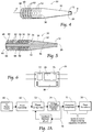
- FIG. 1 depicts an embodiment of a handheld ultrasonic device 10 according to the present disclosure that is described in the context of a dental device for use in dental procedures.
- the device 10 generally includes a body 20 having a distal end 22 and a proximal handle end 24.
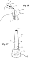
- the proximal end 24 can connect to a power source (not shown), that can be a rechargeable energy source such as a supercapacitor, a lithium ion, nickel cadmium or similar battery, a charging station ( FIG. 17 ), or a combination of batteries and a charging station.
- Cavitation can be advantageous for various treatments, as cavitation can provide superior cleaning and disinfection as compared with other techniques for cleaning and disinfection.
- the present disclosure contemplates the use of treatment tips that can create cavitation within various treatment areas, including root canals, perio pockets or other restricted spaces where displacement of such a tip would be limited or confined.
- this description of the piezoelectric transducer can only be used for frequencies in the vicinity of the mechanical intrinsic resonance. By changing the dimensions and contours of the transducer masses, or by changing how the transducer is loaded, the operating frequency along with electrical and acoustic characteristics can be customized for specific applications.
- transducer Further amplification and mechanical efficiency of the transducer can be accomplished using known techniques, such as changing the internal faces of the masses that contact the piezoelectric elements to help propagate ultrasonic waves through the masses. Shallow cavities on the inner surfaces of the masses can create a mechanical transformer, whereby a portion of the radial motion of the ceramic driving elements is transferred and amplified by the metal plates in axial direction.
- FIG. 8 is an example illustration of an embodiment 170 of the circuitry of the device 10.
- the circuitry 170 includes an inverter 172, and a frequency divider 174. Additional circuit elements can provide the ability to regulate both incoming and outgoing voltage.
- FIG. 9 illustrates a general schematic illustrating one potential flow of current through the device 10 according to the embodiment incorporating the circuitry 170 illustrated in FIG. 8 .
- current flows from the power supply 80 to the inverter 172.
- the applied voltage is delivered in a sine wave or impulse waveform in the Megahertz range.
- the inverter 172 thereby inverts the incoming direct current from the battery 80 to achieve this.
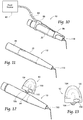
- FIG. 12 shows a radially mounted fluid source 92 that can include a fillable non-powered fluid source 100.
- the non-powered fluid source shown here is an elastomeric pump.
- the elastomeric pump 100 includes an input 102, an elastomeric bladder 104, and an output 106 (see FIG. 13 ).
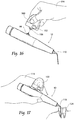
- the input 102 can be configured to receive a syringe 122 (see FIG. 15 ) and can include a one-way valve.
- the output 106 can also include a one-way valve and can be removably attached and operatively connected to the internal fluid line 90 through a connector 94 located on the periphery of the device 10.
- FIG. 19 exemplifies a charging station 116 that can be plugged into any standard A/C outlet (e.g., 120V or 240V) to recharge the power supply 80.
- the power supply can alternatively be recharged by direct electrical contact charging or by induction charging.
- the device body 302 supports the circuitry 312 and the rechargeable energy source 313 at the proximal end 306 of the device 300.
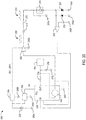
- the circuitry 312 can be similar or identical to the circuitry 200 shown in FIG. 20 .
- the rechargeable energy source can be a DC battery, a supercapacitor, a rechargeable battery, a lithium ion battery, the like, or combinations thereof.
- the rechargeable energy source can be combined with or omitted in place of any other energy source known in the art.
- the rechargeable energy source can be omitted from the device, for example, in the case of a wired device that is electrically connected to an external energy source such as an external battery or a building outlet.
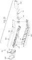
- the body 302 supports a piezoelectric transducer 314 at the distal end 304 of the device 300.
- the piezoelectric transducer 314 can be similar or identical to the piezoelectric transducer 30 shown in FIG. 5 .
Landscapes
- Health & Medical Sciences (AREA)
- Veterinary Medicine (AREA)
- Life Sciences & Earth Sciences (AREA)
- Animal Behavior & Ethology (AREA)
- General Health & Medical Sciences (AREA)
- Public Health (AREA)
- Dentistry (AREA)
- Epidemiology (AREA)
- Engineering & Computer Science (AREA)
- Oral & Maxillofacial Surgery (AREA)
- Mechanical Engineering (AREA)
- Water Supply & Treatment (AREA)
- Biomedical Technology (AREA)
- Nuclear Medicine, Radiotherapy & Molecular Imaging (AREA)
- Radiology & Medical Imaging (AREA)
- Dental Tools And Instruments Or Auxiliary Dental Instruments (AREA)
- Inverter Devices (AREA)
- Apparatuses For Generation Of Mechanical Vibrations (AREA)
- Dc-Dc Converters (AREA)
- Oscillators With Electromechanical Resonators (AREA)
Claims (15)
- Vorrichtung, umfassend:
eine Schaltung (200), umfassend:mindestens einen Hochsetzsteller (204), der Leistung von einer Energiequelle (202) empfängt;einen Rechteckwellentreiber (208) in Reihe mit dem Hochsetzsteller (204);einen Induktor (212) in Reihe mit dem Rechteckwellentreiber (208) zum Umwandeln einer Rechteckwelle in eine sinusförmige Welle; undeinen distal angebrachten piezoelektrischen Wandler (218) in Reihe mit dem Induktor (212), wobei der piezoelektrische Wandler (218) mit einer Last verbindbar ist; undeinen Phasenregelkreis (238), der mit der Schaltung gekoppelt ist, um eine Resonanzfrequenz des piezoelektrischen Wandlers (218) zu bestimmen, wenn der piezoelektrische Wandler (218) mit der Last verbunden ist;wobei der Wandler (218) eine Länge von 40 bis 60 mm hat und aufweist: eine belastete Resonanzfrequenz zwischen 25 und 50 kHz, eine Rückmasse mit einem ersten Ende (64) der Rückmasse und einem zweiten Ende (66) der Rückmasse und beinhaltend einen Festkörper mit einer Reihe von Ringen (62) mit unterschiedlichen Radien,einen Stapel umfassend 2 bis 8 piezoelektrischen Scheiben, die elektrisch parallel geschaltet und mechanisch in Reihe geschaltet sind, undein sich verjüngendes Horn;wobei die Schaltung eine angelegte Spannungswellenform zwischen 100 und 800 Volt von Spitze zu Spitze erzeugen kann; unddie Vorrichtung eine Fluidabgabequelle umfasst, die in der Lage ist, Strömungsraten zwischen 0,01 ml und 20 ml pro Minute zu einer Behandlungsstelle zu erzeugen. - Vorrichtung nach Anspruch 1, wobei die Energiequelle eine wiederaufladbare Gleichstrombatterie (202) ist und wobei die Energiequelle in die Schaltung integriert ist.
- Vorrichtung nach Anspruch 1, wobei die Schaltung ferner einen Kondensator (210) in Reihe mit dem Induktor (212) umfasst, um die Gleichstromkomponente des piezoelektrischen Wandlers (218) zu entfernen.
- Vorrichtung nach Anspruch 1, wobei die Schaltung ferner einen Kondensator parallel zum piezoelektrischen Wandler (218) umfasst, um mindestens einen Schwingungsmodus der 3. Harmonischen des piezoelektrischen Wandlers zu unterdrücken.
- Vorrichtung nach Anspruch 1, wobei die Schaltung ferner ein Paar aufeinander folgende Dioden (220, 222) in Reihe mit dem Wandler (218) umfasst, um die Phase des durch den Wandler (218) fließenden Stroms zu bestimmen, so dass er in einen Phasenkomparator des Phasenregelkreises (238) eingespeist werden kann.
- Vorrichtung nach Anspruch 5, wobei die Dioden parallel zueinander konfiguriert und mit Masse verbunden sind.
- Vorrichtung nach Anspruch 5 oder 6, ferner umfassend einen Spannungskomparator (224) mit einem Eingang, der mit einer Verbindungsstelle des piezoelektrischen Wandlers (218), der ersten Diode (220) und der zweiten Diode (222) verbunden ist.
- Vorrichtung nach Anspruch 2, wobei die Schaltung ferner einen zweiten Hochsetzsteller (206) umfasst, der von der Gleichstrombatterie (202) mit Strom versorgt wird.
- Vorrichtung nach Anspruch 8, wobei der Ausgang des zweiten Hochsetzstellers (206) dem Phasenregelkreis (238) Strom bereitstellt.
- Vorrichtung nach Anspruch 1, wobei die Last eine Behandlungsspitze für einen zahnärztlichen oder einen medizinischen Eingriff ist.
- Vorrichtung nach Anspruch 1, wobei die Vorrichtung eine drahtlose Handultraschallvorrichtung ist, die einen Vorrichtungskörper mit einem distalen Ende zum Koppeln an mindestens eine Behandlungsspitze umfasst.
- Handultraschallvorrichtung nach Anspruch 11, wobei die Fluidabgabequelle eine Fluidpumpe (318) umfasst, und wobei die Fluidpumpe eine einer elastomeren Infusionspumpe und einer piezoelektrischen Pumpe ist.
- Vorrichtung nach einem der vorhergehenden Ansprüche, wobei der Phasenregelkreis (238) konfiguriert ist, um die Antriebsspannung mit der Phase des Stroms durch den Wandler (218) zu synchronisieren; und
wobei die Vorrichtung eine Frequenzbegrenzungsschaltung umfasst, die mit dem Phasenregelkreis (238) gekoppelt ist. - Vorrichtung nach einem der vorhergehenden Ansprüche, wobei der Phasenregelkreis (238) einen Phasenkomparator mit einem Ausgang umfasst, der zu einem Tiefpassfilter geht, der in einen spannungsgesteuerten Oszillator (240) einspeist.
- Vorrichtung nach Anspruch 7, wobei der Phasenregelkreis (238) einen Phasenkomparator mit einem Ausgang umfasst, der zu einem Tiefpassfilter geht, der in einen spannungsgesteuerten Oszillator (240) einspeist, und
wobei der Phasenkomparator einen Eingang vom Spannungskomparator (224) und vom spannungsgesteuerten Oszillator (240) empfängt.
Priority Applications (1)
| Application Number | Priority Date | Filing Date | Title |
|---|---|---|---|
| EP18159288.2A EP3348332B1 (de) | 2013-12-27 | 2014-12-29 | Piezoelektrische vorrichtung und schaltkreis |
Applications Claiming Priority (3)
| Application Number | Priority Date | Filing Date | Title |
|---|---|---|---|
| US201361921294P | 2013-12-27 | 2013-12-27 | |
| US201461986563P | 2014-04-30 | 2014-04-30 | |
| PCT/US2014/072589 WO2015100457A1 (en) | 2013-12-27 | 2014-12-29 | Piezoelectric device and circuitry |
Related Child Applications (2)
| Application Number | Title | Priority Date | Filing Date |
|---|---|---|---|
| EP18159288.2A Division-Into EP3348332B1 (de) | 2013-12-27 | 2014-12-29 | Piezoelektrische vorrichtung und schaltkreis |
| EP18159288.2A Division EP3348332B1 (de) | 2013-12-27 | 2014-12-29 | Piezoelektrische vorrichtung und schaltkreis |
Publications (2)
| Publication Number | Publication Date |
|---|---|
| EP3086884A1 EP3086884A1 (de) | 2016-11-02 |
| EP3086884B1 true EP3086884B1 (de) | 2019-12-11 |
Family
ID=52464552
Family Applications (2)
| Application Number | Title | Priority Date | Filing Date |
|---|---|---|---|
| EP14835645.4A Active EP3086884B1 (de) | 2013-12-27 | 2014-12-29 | Piezoelektrische vorrichtung und schaltkreis |
| EP18159288.2A Active EP3348332B1 (de) | 2013-12-27 | 2014-12-29 | Piezoelektrische vorrichtung und schaltkreis |
Family Applications After (1)
| Application Number | Title | Priority Date | Filing Date |
|---|---|---|---|
| EP18159288.2A Active EP3348332B1 (de) | 2013-12-27 | 2014-12-29 | Piezoelektrische vorrichtung und schaltkreis |
Country Status (6)
| Country | Link |
|---|---|
| US (4) | US9700382B2 (de) |
| EP (2) | EP3086884B1 (de) |
| JP (4) | JP6360564B2 (de) |
| CN (2) | CN104994967B (de) |
| ES (1) | ES2946793T3 (de) |
| WO (1) | WO2015100457A1 (de) |
Families Citing this family (36)
| Publication number | Priority date | Publication date | Assignee | Title |
|---|---|---|---|---|
| US10835355B2 (en) | 2006-04-20 | 2020-11-17 | Sonendo, Inc. | Apparatus and methods for treating root canals of teeth |
| EP4272694A3 (de) | 2006-04-20 | 2024-01-03 | Sonendo, Inc. | Vorrichtung zur behandlung von wurzelkanälen von zähnen |
| US12114924B2 (en) | 2006-08-24 | 2024-10-15 | Pipstek, Llc | Treatment system and method |
| US7980854B2 (en) | 2006-08-24 | 2011-07-19 | Medical Dental Advanced Technologies Group, L.L.C. | Dental and medical treatments and procedures |
| JP5902096B2 (ja) | 2009-11-13 | 2016-04-13 | ソネンド インコーポレイテッド | 歯科治療のための液体噴射装置および方法 |
| BR112013009708A2 (pt) | 2010-10-21 | 2016-07-19 | Sonendo Inc | aparelhos, métodos e composições para tratamento endodôntico |
| US11173019B2 (en) | 2012-03-22 | 2021-11-16 | Sonendo, Inc. | Apparatus and methods for cleaning teeth |
| US10631962B2 (en) | 2012-04-13 | 2020-04-28 | Sonendo, Inc. | Apparatus and methods for cleaning teeth and gingival pockets |
| ES2883954T3 (es) | 2012-12-20 | 2021-12-09 | Sonendo Inc | Aparato de limpieza de dientes y de conductos radiculares |
| US10363120B2 (en) | 2012-12-20 | 2019-07-30 | Sonendo, Inc. | Apparatus and methods for cleaning teeth and root canals |
| EP2991576B1 (de) | 2013-05-01 | 2022-12-28 | Sonendo, Inc. | Vorrichtung und system zur behandlung von zähnen |
| US9877801B2 (en) | 2013-06-26 | 2018-01-30 | Sonendo, Inc. | Apparatus and methods for filling teeth and root canals |
| CN104994967B (zh) * | 2013-12-27 | 2018-05-01 | 英特尔梅迪股份有限公司 | 压电设备和电路 |
| US10729974B2 (en) | 2015-04-03 | 2020-08-04 | SonicSensory, Inc. | Modular system for building variable interactive platforms and enclosures for deep multisensory immersion into audio and audio-visual entertainment |
| US10172688B2 (en) * | 2015-06-24 | 2019-01-08 | Carlos Andres Castro-Perdomo | Steam cleaning device and methods of use |
| US10806544B2 (en) | 2016-04-04 | 2020-10-20 | Sonendo, Inc. | Systems and methods for removing foreign objects from root canals |
| EP3632366B1 (de) * | 2016-09-11 | 2021-06-02 | Tulsa Dental Products LLC | System zur bereitstellung von endodontischem material mittels induktionserwärmung |
| FR3062296B1 (fr) * | 2017-01-30 | 2021-10-22 | Soc Pour La Conception Des Applications Des Techniques Electroniques | Appareil de traitement a ultrasons avec controle automatique de consigne |
| KR101962534B1 (ko) * | 2017-05-24 | 2019-03-26 | 서울대학교산학협력단 | 근관 치료장치 |
| TWI635883B (zh) * | 2017-08-30 | 2018-09-21 | 中原大學 | 壓電式超音波熱電療系統 |
| CN109453461B (zh) * | 2017-09-06 | 2022-05-27 | 中原大学 | 压电式超音波热电疗系统 |
| US11194028B2 (en) * | 2017-09-12 | 2021-12-07 | Semiconductor Components Industries, Llc | Measuring resonance parameters of piezoelectric transducers |
| CN109077818B (zh) * | 2018-07-03 | 2021-01-19 | 付少平 | 一种根管充填器械 |
| CN112512457A (zh) * | 2018-08-07 | 2021-03-16 | 柯林·C·帕姆奎斯特 | 电动牙科手机以及可穿戴控制器 |
| JP2021007656A (ja) * | 2019-07-01 | 2021-01-28 | 義人 上田 | 歯周ポケット薬液注入器 |
| WO2021152049A1 (en) * | 2020-01-28 | 2021-08-05 | Ferton Holding S.A. | Tool for a medical treatment, preferably a dental treatment, and method for operating such a tool |
| JP6890199B1 (ja) | 2020-07-01 | 2021-06-18 | 株式会社ロッテ | チョコレート |
| KR20230070014A (ko) * | 2020-09-21 | 2023-05-19 | 비카 알렉산더 비간드 에스이 운트 코. 케이쥐. | 무선 센서 모듈 및 무선 센서 모듈을 구성하는 모듈러 시스템 |
| USD997355S1 (en) | 2020-10-07 | 2023-08-29 | Sonendo, Inc. | Dental treatment instrument |
| CN117320661A (zh) * | 2021-05-18 | 2023-12-29 | 卢门多股份公司 | 牙髓设备和方法 |
| KR20240146060A (ko) * | 2022-02-07 | 2024-10-07 | 파슈케 울트라소닉 엘엘씨 | 무선 배터리 구동 핸드헬드 초음파 치과 스케일링 시스템 |
| CN114769693B (zh) * | 2022-04-26 | 2023-12-19 | 南京工程学院 | 一种用于超声辅助铣削的扭振刀具平台及其测试系统 |
| USD1118938S1 (en) | 2022-09-23 | 2026-03-17 | Sonendo, Inc. | Dental console |
| NL2035728B1 (en) | 2023-09-03 | 2025-03-13 | Univ Delft Tech | Electrical pulser for a load having a capacitance |
| CN223143616U (zh) * | 2024-08-05 | 2025-07-25 | 珠海大拇指创新科技有限公司 | 一种冲牙器 |
| WO2026064474A1 (en) * | 2024-09-18 | 2026-03-26 | Paschke Ultrasonix Llc | Ergonomic ultrasonic dental scaling devices |
Citations (2)
| Publication number | Priority date | Publication date | Assignee | Title |
|---|---|---|---|---|
| US20070166663A1 (en) * | 2006-01-18 | 2007-07-19 | Telles Heidi A | Cordless ultrasonic dental scaler |
| US20090036912A1 (en) * | 2007-07-31 | 2009-02-05 | Wiener Eitan T | Ultrasonic surgical instruments |
Family Cites Families (25)
| Publication number | Priority date | Publication date | Assignee | Title |
|---|---|---|---|---|
| HU178505B (en) * | 1979-05-14 | 1982-05-28 | Tibor Dery | Device for determining and digital signalling the position of root treating instruments in the root duct |
| US3596206A (en) | 1969-11-06 | 1971-07-27 | Walter J Loria | Transistor oscillator including ultrasonic generator crystal |
| US3651352A (en) | 1970-12-10 | 1972-03-21 | Branson Instr | Oscillatory circuit for ultrasonic cleaning apparatus |
| US3975650A (en) * | 1975-01-30 | 1976-08-17 | Payne Stephen C | Ultrasonic generator drive circuit |
| US4168447A (en) | 1977-02-25 | 1979-09-18 | Bussiere Ronald L | Prestressed cylindrical piezoelectric ultrasonic scaler |
| US4445063A (en) | 1982-07-26 | 1984-04-24 | Solid State Systems, Corporation | Energizing circuit for ultrasonic transducer |
| US4965532A (en) * | 1988-06-17 | 1990-10-23 | Olympus Optical Co., Ltd. | Circuit for driving ultrasonic transducer |
| US6157821A (en) * | 1997-10-23 | 2000-12-05 | Ericsson Inc. | Voltage step up for a low voltage frequency synthesizer architecture |
| US7622845B2 (en) * | 2003-03-31 | 2009-11-24 | Suren Systems, Ltd. | Piezoelectric transducer signal processing circuit |
| US7396336B2 (en) | 2003-10-30 | 2008-07-08 | Sherwood Services Ag | Switched resonant ultrasonic power amplifier system |
| US7538473B2 (en) * | 2004-02-03 | 2009-05-26 | S.C. Johnson & Son, Inc. | Drive circuits and methods for ultrasonic piezoelectric actuators |
| US20060241524A1 (en) * | 2005-03-11 | 2006-10-26 | Qi Yu | Intravascular ultrasound catheter device and method for ablating atheroma |
| US20070080609A1 (en) * | 2005-04-27 | 2007-04-12 | Cleaning Technology Group Llc | Low loss ultrasound transducers |
| US20070085614A1 (en) * | 2005-09-06 | 2007-04-19 | Joseph Lockhart | Methods of enabling or disabling ultrasound vibration devices of ultrasound medical devices |
| GB2434266A (en) * | 2006-01-17 | 2007-07-18 | Dyson Technology Ltd | Agitation source drive circuit |
| US8328738B2 (en) * | 2007-06-29 | 2012-12-11 | Actuated Medical, Inc. | Medical tool for reduced penetration force with feedback means |
| US9017355B2 (en) | 2007-12-03 | 2015-04-28 | Covidien Ag | Battery-powered hand-held ultrasonic surgical cautery cutting device |
| US9024507B2 (en) * | 2008-07-10 | 2015-05-05 | Cornell University | Ultrasound wave generating apparatus |
| CN101632984B (zh) * | 2008-07-24 | 2014-09-17 | Ge医疗系统环球技术有限公司 | 电压产生电路及超声波诊断装置 |
| WO2010030850A2 (en) * | 2008-09-12 | 2010-03-18 | Ethicon Endo-Surgery, Inc. | Ultrasonic device for fingertip control |
| ATE533427T1 (de) * | 2009-12-10 | 2011-12-15 | W & H Dentalwerk Buermoos Gmbh | Medizinische, insbesondere dentale, behandlungsvorrichtung zur abgabe eines mediums |
| CN103547380B (zh) * | 2011-08-19 | 2015-10-07 | 奥林巴斯医疗株式会社 | 超声波产生装置及其制造方法、超声波处理装置及其制造方法 |
| US20130331875A1 (en) * | 2012-06-11 | 2013-12-12 | Covidien Lp | Temperature estimation and tissue detection of an ultrasonic dissector from frequency response monitoring |
| US20140128779A1 (en) * | 2012-11-06 | 2014-05-08 | Sheldon Gibson | Medical device for removing pathogens |
| CN104994967B (zh) * | 2013-12-27 | 2018-05-01 | 英特尔梅迪股份有限公司 | 压电设备和电路 |
-
2014
- 2014-12-29 CN CN201480002498.3A patent/CN104994967B/zh not_active Ceased
- 2014-12-29 US US14/584,917 patent/US9700382B2/en active Active
- 2014-12-29 US US15/108,033 patent/US10213272B2/en active Active
- 2014-12-29 ES ES18159288T patent/ES2946793T3/es active Active
- 2014-12-29 EP EP14835645.4A patent/EP3086884B1/de active Active
- 2014-12-29 EP EP18159288.2A patent/EP3348332B1/de active Active
- 2014-12-29 CN CN201810309519.6A patent/CN108478293B/zh not_active Ceased
- 2014-12-29 WO PCT/US2014/072589 patent/WO2015100457A1/en not_active Ceased
- 2014-12-29 JP JP2016561992A patent/JP6360564B2/ja active Active
-
2018
- 2018-06-19 JP JP2018115682A patent/JP6677763B2/ja active Active
-
2019
- 2019-02-25 US US16/284,836 patent/US11648083B2/en active Active
-
2020
- 2020-03-13 JP JP2020043679A patent/JP7026370B2/ja active Active
-
2022
- 2022-02-04 JP JP2022016061A patent/JP7369474B2/ja active Active
-
2023
- 2023-04-11 US US18/133,414 patent/US20230240796A1/en active Pending
Patent Citations (2)
| Publication number | Priority date | Publication date | Assignee | Title |
|---|---|---|---|---|
| US20070166663A1 (en) * | 2006-01-18 | 2007-07-19 | Telles Heidi A | Cordless ultrasonic dental scaler |
| US20090036912A1 (en) * | 2007-07-31 | 2009-02-05 | Wiener Eitan T | Ultrasonic surgical instruments |
Also Published As
| Publication number | Publication date |
|---|---|
| JP2022064998A (ja) | 2022-04-26 |
| JP2020114393A (ja) | 2020-07-30 |
| JP7369474B2 (ja) | 2023-10-26 |
| HK1216627A1 (zh) | 2016-11-25 |
| WO2015100457A1 (en) | 2015-07-02 |
| ES2946793T3 (es) | 2023-07-26 |
| EP3348332A1 (de) | 2018-07-18 |
| JP7026370B2 (ja) | 2022-02-28 |
| JP6360564B2 (ja) | 2018-07-18 |
| CN108478293B (zh) | 2021-01-29 |
| US9700382B2 (en) | 2017-07-11 |
| US20230240796A1 (en) | 2023-08-03 |
| EP3086884A1 (de) | 2016-11-02 |
| CN108478293A (zh) | 2018-09-04 |
| US20160324596A1 (en) | 2016-11-10 |
| JP2018171470A (ja) | 2018-11-08 |
| EP3348332C0 (de) | 2023-06-07 |
| US10213272B2 (en) | 2019-02-26 |
| CN104994967B (zh) | 2018-05-01 |
| CN104994967A (zh) | 2015-10-21 |
| US20150188023A1 (en) | 2015-07-02 |
| JP6677763B2 (ja) | 2020-04-08 |
| US11648083B2 (en) | 2023-05-16 |
| US20190357996A1 (en) | 2019-11-28 |
| JP2017503470A (ja) | 2017-01-26 |
| EP3348332B1 (de) | 2023-06-07 |
Similar Documents
| Publication | Publication Date | Title |
|---|---|---|
| US20230240796A1 (en) | Piezoelectric device and circuitry | |
| AU688384B2 (en) | Bipolar ultrasonic surgery | |
| CN108697457B (zh) | 包括细长多层轴的模块化电池供电手持式外科器械 | |
| JP2020114393A5 (de) | ||
| JP2017503470A5 (de) | ||
| WO1984003828A1 (fr) | Oscillateur ultrasonique | |
| JP2019503230A (ja) | ボタンの変位、強度、又は局所組織特性化に基づくエネルギーの選択的印加を伴うモジュール電池式手持ち型外科用器具 | |
| AU4858893A (en) | An ultrasonic surgical handpiece and an energy initiator to maintain the vibration and linear dynamics | |
| CN1812749A (zh) | 带有光源的超声牙科器械 | |
| KR20130133647A (ko) | 트리트먼트 장치 | |
| US10736686B2 (en) | Surgical device employing a cantilevered beam dissector | |
| US20200253631A1 (en) | Control System For An Ultrasonic Surgical Handpiece | |
| CN106031660A (zh) | 一种无线正畸辅助治疗仪 | |
| HK1260550A1 (en) | Piezoelectric device and circuitry | |
| HK1260550B (zh) | 压电设备和电路 | |
| HK1216627B (en) | Piezoelectric device and circuitry | |
| CN104734374A (zh) | 基于超声波的无线充电方法 | |
| BE1018486A4 (nl) | Medisch-tandheelkundige instrumenten. | |
| JP2020058483A (ja) | 歯間のスペースメイキング装置およびスペースメイキング方法 |
Legal Events
| Date | Code | Title | Description |
|---|---|---|---|
| PUAI | Public reference made under article 153(3) epc to a published international application that has entered the european phase |
Free format text: ORIGINAL CODE: 0009012 |
|
| 17P | Request for examination filed |
Effective date: 20160726 |
|
| AK | Designated contracting states |
Kind code of ref document: A1 Designated state(s): AL AT BE BG CH CY CZ DE DK EE ES FI FR GB GR HR HU IE IS IT LI LT LU LV MC MK MT NL NO PL PT RO RS SE SI SK SM TR |
|
| AX | Request for extension of the european patent |
Extension state: BA ME |
|
| DAX | Request for extension of the european patent (deleted) | ||
| STAA | Information on the status of an ep patent application or granted ep patent |
Free format text: STATUS: EXAMINATION IS IN PROGRESS |
|
| 17Q | First examination report despatched |
Effective date: 20180615 |
|
| GRAP | Despatch of communication of intention to grant a patent |
Free format text: ORIGINAL CODE: EPIDOSNIGR1 |
|
| STAA | Information on the status of an ep patent application or granted ep patent |
Free format text: STATUS: GRANT OF PATENT IS INTENDED |
|
| INTG | Intention to grant announced |
Effective date: 20190621 |
|
| GRAS | Grant fee paid |
Free format text: ORIGINAL CODE: EPIDOSNIGR3 |
|
| GRAA | (expected) grant |
Free format text: ORIGINAL CODE: 0009210 |
|
| STAA | Information on the status of an ep patent application or granted ep patent |
Free format text: STATUS: THE PATENT HAS BEEN GRANTED |
|
| AK | Designated contracting states |
Kind code of ref document: B1 Designated state(s): AL AT BE BG CH CY CZ DE DK EE ES FI FR GB GR HR HU IE IS IT LI LT LU LV MC MK MT NL NO PL PT RO RS SE SI SK SM TR |
|
| REG | Reference to a national code |
Ref country code: GB Ref legal event code: FG4D |
|
| REG | Reference to a national code |
Ref country code: CH Ref legal event code: EP |
|
| REG | Reference to a national code |
Ref country code: AT Ref legal event code: REF Ref document number: 1211676 Country of ref document: AT Kind code of ref document: T Effective date: 20191215 |
|
| REG | Reference to a national code |
Ref country code: DE Ref legal event code: R096 Ref document number: 602014058359 Country of ref document: DE |
|
| REG | Reference to a national code |
Ref country code: IE Ref legal event code: FG4D |
|
| REG | Reference to a national code |
Ref country code: NL Ref legal event code: MP Effective date: 20191211 |
|
| REG | Reference to a national code |
Ref country code: LT Ref legal event code: MG4D |
|
| PG25 | Lapsed in a contracting state [announced via postgrant information from national office to epo] |
Ref country code: BG Free format text: LAPSE BECAUSE OF FAILURE TO SUBMIT A TRANSLATION OF THE DESCRIPTION OR TO PAY THE FEE WITHIN THE PRESCRIBED TIME-LIMIT Effective date: 20200311 Ref country code: NO Free format text: LAPSE BECAUSE OF FAILURE TO SUBMIT A TRANSLATION OF THE DESCRIPTION OR TO PAY THE FEE WITHIN THE PRESCRIBED TIME-LIMIT Effective date: 20200311 Ref country code: FI Free format text: LAPSE BECAUSE OF FAILURE TO SUBMIT A TRANSLATION OF THE DESCRIPTION OR TO PAY THE FEE WITHIN THE PRESCRIBED TIME-LIMIT Effective date: 20191211 Ref country code: GR Free format text: LAPSE BECAUSE OF FAILURE TO SUBMIT A TRANSLATION OF THE DESCRIPTION OR TO PAY THE FEE WITHIN THE PRESCRIBED TIME-LIMIT Effective date: 20200312 Ref country code: LV Free format text: LAPSE BECAUSE OF FAILURE TO SUBMIT A TRANSLATION OF THE DESCRIPTION OR TO PAY THE FEE WITHIN THE PRESCRIBED TIME-LIMIT Effective date: 20191211 Ref country code: SE Free format text: LAPSE BECAUSE OF FAILURE TO SUBMIT A TRANSLATION OF THE DESCRIPTION OR TO PAY THE FEE WITHIN THE PRESCRIBED TIME-LIMIT Effective date: 20191211 Ref country code: LT Free format text: LAPSE BECAUSE OF FAILURE TO SUBMIT A TRANSLATION OF THE DESCRIPTION OR TO PAY THE FEE WITHIN THE PRESCRIBED TIME-LIMIT Effective date: 20191211 |
|
| PG25 | Lapsed in a contracting state [announced via postgrant information from national office to epo] |
Ref country code: HR Free format text: LAPSE BECAUSE OF FAILURE TO SUBMIT A TRANSLATION OF THE DESCRIPTION OR TO PAY THE FEE WITHIN THE PRESCRIBED TIME-LIMIT Effective date: 20191211 Ref country code: RS Free format text: LAPSE BECAUSE OF FAILURE TO SUBMIT A TRANSLATION OF THE DESCRIPTION OR TO PAY THE FEE WITHIN THE PRESCRIBED TIME-LIMIT Effective date: 20191211 |
|
| PG25 | Lapsed in a contracting state [announced via postgrant information from national office to epo] |
Ref country code: AL Free format text: LAPSE BECAUSE OF FAILURE TO SUBMIT A TRANSLATION OF THE DESCRIPTION OR TO PAY THE FEE WITHIN THE PRESCRIBED TIME-LIMIT Effective date: 20191211 |
|
| PG25 | Lapsed in a contracting state [announced via postgrant information from national office to epo] |
Ref country code: NL Free format text: LAPSE BECAUSE OF FAILURE TO SUBMIT A TRANSLATION OF THE DESCRIPTION OR TO PAY THE FEE WITHIN THE PRESCRIBED TIME-LIMIT Effective date: 20191211 Ref country code: ES Free format text: LAPSE BECAUSE OF FAILURE TO SUBMIT A TRANSLATION OF THE DESCRIPTION OR TO PAY THE FEE WITHIN THE PRESCRIBED TIME-LIMIT Effective date: 20191211 Ref country code: EE Free format text: LAPSE BECAUSE OF FAILURE TO SUBMIT A TRANSLATION OF THE DESCRIPTION OR TO PAY THE FEE WITHIN THE PRESCRIBED TIME-LIMIT Effective date: 20191211 Ref country code: CZ Free format text: LAPSE BECAUSE OF FAILURE TO SUBMIT A TRANSLATION OF THE DESCRIPTION OR TO PAY THE FEE WITHIN THE PRESCRIBED TIME-LIMIT Effective date: 20191211 Ref country code: RO Free format text: LAPSE BECAUSE OF FAILURE TO SUBMIT A TRANSLATION OF THE DESCRIPTION OR TO PAY THE FEE WITHIN THE PRESCRIBED TIME-LIMIT Effective date: 20191211 Ref country code: PT Free format text: LAPSE BECAUSE OF FAILURE TO SUBMIT A TRANSLATION OF THE DESCRIPTION OR TO PAY THE FEE WITHIN THE PRESCRIBED TIME-LIMIT Effective date: 20200506 |
|
| REG | Reference to a national code |
Ref country code: CH Ref legal event code: PL |
|
| REG | Reference to a national code |
Ref country code: BE Ref legal event code: MM Effective date: 20191231 |
|
| PG25 | Lapsed in a contracting state [announced via postgrant information from national office to epo] |
Ref country code: SM Free format text: LAPSE BECAUSE OF FAILURE TO SUBMIT A TRANSLATION OF THE DESCRIPTION OR TO PAY THE FEE WITHIN THE PRESCRIBED TIME-LIMIT Effective date: 20191211 Ref country code: SK Free format text: LAPSE BECAUSE OF FAILURE TO SUBMIT A TRANSLATION OF THE DESCRIPTION OR TO PAY THE FEE WITHIN THE PRESCRIBED TIME-LIMIT Effective date: 20191211 Ref country code: IS Free format text: LAPSE BECAUSE OF FAILURE TO SUBMIT A TRANSLATION OF THE DESCRIPTION OR TO PAY THE FEE WITHIN THE PRESCRIBED TIME-LIMIT Effective date: 20200411 |
|
| REG | Reference to a national code |
Ref country code: DE Ref legal event code: R097 Ref document number: 602014058359 Country of ref document: DE |
|
| PG25 | Lapsed in a contracting state [announced via postgrant information from national office to epo] |
Ref country code: MC Free format text: LAPSE BECAUSE OF FAILURE TO SUBMIT A TRANSLATION OF THE DESCRIPTION OR TO PAY THE FEE WITHIN THE PRESCRIBED TIME-LIMIT Effective date: 20191211 |
|
| REG | Reference to a national code |
Ref country code: AT Ref legal event code: MK05 Ref document number: 1211676 Country of ref document: AT Kind code of ref document: T Effective date: 20191211 |
|
| PLBE | No opposition filed within time limit |
Free format text: ORIGINAL CODE: 0009261 |
|
| STAA | Information on the status of an ep patent application or granted ep patent |
Free format text: STATUS: NO OPPOSITION FILED WITHIN TIME LIMIT |
|
| PG25 | Lapsed in a contracting state [announced via postgrant information from national office to epo] |
Ref country code: DK Free format text: LAPSE BECAUSE OF FAILURE TO SUBMIT A TRANSLATION OF THE DESCRIPTION OR TO PAY THE FEE WITHIN THE PRESCRIBED TIME-LIMIT Effective date: 20191211 Ref country code: IE Free format text: LAPSE BECAUSE OF NON-PAYMENT OF DUE FEES Effective date: 20191229 Ref country code: LU Free format text: LAPSE BECAUSE OF NON-PAYMENT OF DUE FEES Effective date: 20191229 |
|
| 26N | No opposition filed |
Effective date: 20200914 |
|
| PG25 | Lapsed in a contracting state [announced via postgrant information from national office to epo] |
Ref country code: CH Free format text: LAPSE BECAUSE OF NON-PAYMENT OF DUE FEES Effective date: 20191231 Ref country code: AT Free format text: LAPSE BECAUSE OF FAILURE TO SUBMIT A TRANSLATION OF THE DESCRIPTION OR TO PAY THE FEE WITHIN THE PRESCRIBED TIME-LIMIT Effective date: 20191211 Ref country code: LI Free format text: LAPSE BECAUSE OF NON-PAYMENT OF DUE FEES Effective date: 20191231 Ref country code: BE Free format text: LAPSE BECAUSE OF NON-PAYMENT OF DUE FEES Effective date: 20191231 Ref country code: SI Free format text: LAPSE BECAUSE OF FAILURE TO SUBMIT A TRANSLATION OF THE DESCRIPTION OR TO PAY THE FEE WITHIN THE PRESCRIBED TIME-LIMIT Effective date: 20191211 |
|
| PG25 | Lapsed in a contracting state [announced via postgrant information from national office to epo] |
Ref country code: IT Free format text: LAPSE BECAUSE OF FAILURE TO SUBMIT A TRANSLATION OF THE DESCRIPTION OR TO PAY THE FEE WITHIN THE PRESCRIBED TIME-LIMIT Effective date: 20191211 |
|
| PG25 | Lapsed in a contracting state [announced via postgrant information from national office to epo] |
Ref country code: PL Free format text: LAPSE BECAUSE OF FAILURE TO SUBMIT A TRANSLATION OF THE DESCRIPTION OR TO PAY THE FEE WITHIN THE PRESCRIBED TIME-LIMIT Effective date: 20191211 |
|
| PG25 | Lapsed in a contracting state [announced via postgrant information from national office to epo] |
Ref country code: CY Free format text: LAPSE BECAUSE OF FAILURE TO SUBMIT A TRANSLATION OF THE DESCRIPTION OR TO PAY THE FEE WITHIN THE PRESCRIBED TIME-LIMIT Effective date: 20191211 |
|
| PG25 | Lapsed in a contracting state [announced via postgrant information from national office to epo] |
Ref country code: MT Free format text: LAPSE BECAUSE OF FAILURE TO SUBMIT A TRANSLATION OF THE DESCRIPTION OR TO PAY THE FEE WITHIN THE PRESCRIBED TIME-LIMIT Effective date: 20191211 Ref country code: HU Free format text: LAPSE BECAUSE OF FAILURE TO SUBMIT A TRANSLATION OF THE DESCRIPTION OR TO PAY THE FEE WITHIN THE PRESCRIBED TIME-LIMIT; INVALID AB INITIO Effective date: 20141229 |
|
| PG25 | Lapsed in a contracting state [announced via postgrant information from national office to epo] |
Ref country code: TR Free format text: LAPSE BECAUSE OF FAILURE TO SUBMIT A TRANSLATION OF THE DESCRIPTION OR TO PAY THE FEE WITHIN THE PRESCRIBED TIME-LIMIT Effective date: 20191211 |
|
| PG25 | Lapsed in a contracting state [announced via postgrant information from national office to epo] |
Ref country code: MK Free format text: LAPSE BECAUSE OF FAILURE TO SUBMIT A TRANSLATION OF THE DESCRIPTION OR TO PAY THE FEE WITHIN THE PRESCRIBED TIME-LIMIT Effective date: 20191211 |
|
| P01 | Opt-out of the competence of the unified patent court (upc) registered |
Effective date: 20230522 |
|
| PGFP | Annual fee paid to national office [announced via postgrant information from national office to epo] |
Ref country code: GB Payment date: 20251229 Year of fee payment: 12 |
|
| PGFP | Annual fee paid to national office [announced via postgrant information from national office to epo] |
Ref country code: FR Payment date: 20251226 Year of fee payment: 12 |
|
| PGFP | Annual fee paid to national office [announced via postgrant information from national office to epo] |
Ref country code: DE Payment date: 20251229 Year of fee payment: 12 |