EP3086896B1 - Handwerkzeugmaschine - Google Patents
Handwerkzeugmaschine Download PDFInfo
- Publication number
- EP3086896B1 EP3086896B1 EP14875652.1A EP14875652A EP3086896B1 EP 3086896 B1 EP3086896 B1 EP 3086896B1 EP 14875652 A EP14875652 A EP 14875652A EP 3086896 B1 EP3086896 B1 EP 3086896B1
- Authority
- EP
- European Patent Office
- Prior art keywords
- knob
- door
- tool
- bearing flange
- threaded
- Prior art date
- Legal status (The legal status is an assumption and is not a legal conclusion. Google has not performed a legal analysis and makes no representation as to the accuracy of the status listed.)
- Active
Links
Images


Classifications
-
- B—PERFORMING OPERATIONS; TRANSPORTING
- B27—WORKING OR PRESERVING WOOD OR SIMILAR MATERIAL; NAILING OR STAPLING MACHINES IN GENERAL
- B27C—PLANING, DRILLING, MILLING, TURNING OR UNIVERSAL MACHINES FOR WOOD OR SIMILAR MATERIAL
- B27C5/00—Machines designed for producing special profiles or shaped work, e.g. by rotary cutters; Equipment therefor
- B27C5/10—Portable hand-operated wood-milling machines; Routers
-
- B—PERFORMING OPERATIONS; TRANSPORTING
- B23—MACHINE TOOLS; METAL-WORKING NOT OTHERWISE PROVIDED FOR
- B23Q—DETAILS, COMPONENTS, OR ACCESSORIES FOR MACHINE TOOLS, e.g. ARRANGEMENTS FOR COPYING OR CONTROLLING; MACHINE TOOLS IN GENERAL CHARACTERISED BY THE CONSTRUCTION OF PARTICULAR DETAILS OR COMPONENTS; COMBINATIONS OR ASSOCIATIONS OF METAL-WORKING MACHINES, NOT DIRECTED TO A PARTICULAR RESULT
- B23Q16/00—Equipment for precise positioning of tool or work into particular locations not otherwise provided for
- B23Q16/02—Indexing equipment
-
- B—PERFORMING OPERATIONS; TRANSPORTING
- B23—MACHINE TOOLS; METAL-WORKING NOT OTHERWISE PROVIDED FOR
- B23Q—DETAILS, COMPONENTS, OR ACCESSORIES FOR MACHINE TOOLS, e.g. ARRANGEMENTS FOR COPYING OR CONTROLLING; MACHINE TOOLS IN GENERAL CHARACTERISED BY THE CONSTRUCTION OF PARTICULAR DETAILS OR COMPONENTS; COMBINATIONS OR ASSOCIATIONS OF METAL-WORKING MACHINES, NOT DIRECTED TO A PARTICULAR RESULT
- B23Q9/00—Arrangements for supporting or guiding portable metal-working machines or apparatus
- B23Q9/0014—Portable machines provided with or cooperating with guide means supported directly by the workpiece during action
- B23Q9/0028—Portable machines provided with or cooperating with guide means supported directly by the workpiece during action the guide means being fixed only on the machine
-
- Y—GENERAL TAGGING OF NEW TECHNOLOGICAL DEVELOPMENTS; GENERAL TAGGING OF CROSS-SECTIONAL TECHNOLOGIES SPANNING OVER SEVERAL SECTIONS OF THE IPC; TECHNICAL SUBJECTS COVERED BY FORMER USPC CROSS-REFERENCE ART COLLECTIONS [XRACs] AND DIGESTS
- Y10—TECHNICAL SUBJECTS COVERED BY FORMER USPC
- Y10T—TECHNICAL SUBJECTS COVERED BY FORMER US CLASSIFICATION
- Y10T409/00—Gear cutting, milling, or planing
- Y10T409/30—Milling
- Y10T409/306216—Randomly manipulated, work supported, or work following device
- Y10T409/306552—Randomly manipulated
- Y10T409/306608—End mill [e.g., router, etc.]
-
- Y—GENERAL TAGGING OF NEW TECHNOLOGICAL DEVELOPMENTS; GENERAL TAGGING OF CROSS-SECTIONAL TECHNOLOGIES SPANNING OVER SEVERAL SECTIONS OF THE IPC; TECHNICAL SUBJECTS COVERED BY FORMER USPC CROSS-REFERENCE ART COLLECTIONS [XRACs] AND DIGESTS
- Y10—TECHNICAL SUBJECTS COVERED BY FORMER USPC
- Y10T—TECHNICAL SUBJECTS COVERED BY FORMER US CLASSIFICATION
- Y10T409/00—Gear cutting, milling, or planing
- Y10T409/30—Milling
- Y10T409/30784—Milling including means to adustably position cutter
- Y10T409/307952—Linear adjustment
Definitions
- the present invention relates to power tools having a base for supporting the tool, such as trim routers.
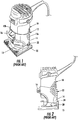
- FIGS. 1-2 One form of conventional trim router or laminate trimmer power tool is shown in FIGS. 1-2 .
- the power tool 10 is carried by a tool support 12 that provides a base or foot plate 15 for supporting the tool on a workpiece.
- the tool support 12 includes a clamping cuff 14 that is configured to support the tool 10 with the working end 11 at a user-selected height above the workpiece.
- the tool support 12 includes a height adjustment assembly 20 with a thumb screw 22 that is used to manually rotate a threaded post 24 within a threaded socket defined between the tool 10 and the tool support 12.
- a clamping device 16 is provided to clamp opposite halves 12a, 12b of the support about the tool once the user-selected height has been attained.
- US 2006/0102248 A1 discloses a depth adjustment mechanism, disposed on a router, that is enabled using a worm drive that includes a shaft member engaging with a rack member.
- the shaft member couples with a sleeve disposed on a base of the router.
- the rack member is coupled with a motor casing of the router.
- the depth adjustment mechanism enables a user selectable engagement of the shaft member with the rack member.
- a rotating member which is coupled with the shaft member, is engaged by a user to displace the shaft member relative to the rack member.
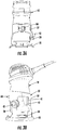
- a tool 10 is shown in FIGS. 3a -b mounted within a tool support 30 according to the present disclosure.
- the tool support 30 includes a base 31 configured to rest on the work surface, and a clamping cuff 32 configured to clamp to the bearing flange 50 of the power tool 10 at adjustable heights.
- the tool support may be provided with a safety lever assembly 80 that is configured and operates similar to the safety levers of prior devices. However, the safety lever assembly 80 is not required for the height adjustment and locking features of the tool support disclosed herein. In another embodiment, the safety lever assembly 80 may be used as an indicator to the user that the tool is engaged into a height adjustment system (as described herein). The assembly 80 may thus incorporate a human readable indicator.
- the clamping cuff defines an opening through which the bearing flange is accessible and a door 40 at the opening and pivotably mounted to the clamping cuff 32 at a hinge 41.
- the hinge includes a biasing element 41a ( FIG. 4 ), such as a torsion spring, leaf spring, spiral spring, serpentine spring or other suitable spring element configured to bias the door to an open position outward or away from the clamping cuff.
- the material of the hinge 41 may be adapted to form the biasing element.
- an electric or electronic component such as a transistor, may be used to form the biasing element.
- An actuator 42 is provided that controls the position of the door 40 and controls both the height adjustment and locking features of the tool support 30 , as described below.
- the actuator 42 includes a knob 47 that is configured to be manually rotated.
- the knob 47 is rotatably attached to a mounting boss 45 on the clamping cuff 32 by way of a mounting screw 44.
- the knob is rotatable to three distinct positions defined by detent recesses 60a, 60b, 60c formed on the surface of the clamping cuff, as best seen in FIG. 10 .
- the knob 47 may include a detent post or cap 62 that is biased by a spring 63 to project outward from the actuator surface 48 of the knob, as shown in FIG. 7 .
- the cap 62 clicks into one of the detents 60a, 60b, 60c when the knob is appropriately aligned.
- the three positions correspond to a "macro" height adjustment position ( FIGS. 4-5 ), a "micro” height adjustment position ( FIGS. 6-7 ) and a locking position ( FIGS. 8-9 ).
- the knob 47 In the "macro" height adjustment position, the knob 47 is rotated to its uppermost position corresponding to the indicia 43a.
- the indicia 43a signifies that the clamping cuff 32 is “unlocked” relative to the bearing flange 50 of the power tool 10.
- the power tool 10 may be manually moved up and down relative to the tool support to effect a "macro" adjustment of the height of the power tool, and more pertinently to position the working end 11 near or in contact with the working surface beneath the base 31.
- the knob 47 includes an actuator surface 48 that faces the door 40 and more particularly the free or opening end 40a of the door.
- a detent projection 54 is defined at the opening end 40a of the door in a position beneath the actuator surface 48.
- the knob 47 defines a recess 52 in the actuator surface facing the door that is configured to receive the detent projection 54.
- the biasing spring 41a biases the door 40 outward to the position shown in FIG. 5 so that the projection 54 seats within the recess 52.
- the height adjustment assembly 34 includes a thumb wheel 35 and a threaded shaft 37.
- the thumb wheel and threaded shaft are carried by the door 40 , and more specifically by a half-bore 38 defined in the door, as shown in FIGS. 5 and 11 .
- the threaded shaft 37 is supported in engagement with the half-bore 38 in the door.
- the bearing flange 50 of the power tool 10 defines the mating threaded half bore 39 so that when the bearing flange and door are directly adjacent the two half-bores combine to form a continuous bore for the height adjustment threaded shaft 37.
- Rotation of the thumb wheel 35 rotates the shaft 37 and the threaded engagement between the shaft and the threaded half-bore 39 in the bearing flange causes the flange 50 to move up and down, depending upon the direction of rotation of the thumb wheel.
- the knob 47 When the knob 47 is rotated to this position the post 62 clicks into the recess 60a and the user has an audible indication that the clamping cuff 32 is able to receive the power tool 10.
- the tool support 30 may be provided with a guide pin 33 ( FIG. 12 ) that operates as an alignment pin projecting inward from the inner surface 32a of the clamping cuff 32.
- the guide pin may interface with a corresponding vertical groove (not shown) defined in the outer surface of the power tool or bearing flange 50 to establish the proper circumferential position of the power tool.
- the guide pin 33 may be mounted, attached or fixed to the clamping cuff in a conventional manner, or may be monolithic component integrated into the inner surface 32a of the cuff 32.
- the macro-adjustment position is provided when the knob 47 is aligned with indicia 43a , as shown in FIGS. 4 .
- the post 62 clicks into the recess 60a and the user has an audible indication that the clamping cuff 32 is able to receive the power tool 10.
- the door 40 is essentially open, meaning that it is offset from the bearing flange 50 so that the threaded half-bore 39 of the bearing flange is offset sufficiently from the half-bore 38 of the door so that the threaded shaft 37 is unable to engage the threads of the bearing flange half-bore.
- the power tool can be moved freely up and down within the clamping cuff. It is, however, contemplated that the bearing flange and clamping cuff will form a close running fit so that there may be some slight resistance to the relative vertical movement.
- the knob 47 can be rotated to the position shown in FIGS. 6-7 corresponding to the "micro" height adjustment position.
- the cap 62 engages the middle recess 60b in the clamping cuff adjacent the indicia 43b signifying that the height of the power tool can be adjusted using the thumb wheel 35.
- FIG. 7 in this position the free end 40a of the door 40 is pushed inward toward the bearing flange 50 of the power tool. This movement may be caused by the detent projection 54 contacting a shallow detent recess 52 in the actuator surface 48 of the knob 47.
- the tool support includes a force generating component for applying a selectable force to the door to first move the door into a position immediately adjacent the bearing flange to form the bore between the two half-bores 38, 39 , and then to subsequently apply a greater force to clamp the threaded shaft 37 between the half-bores.
- the force generating component includes a leaf spring 67 mounted to the actuator surface 48 of the knob, as best shown in FIGS. 9 and 10 .
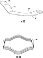
- the leaf spring 67 can be configured as shown in FIGS. 12-13 to include three portions 67a, 67b, 67c. The end of the leaf spring adjacent the portion 67a is fastened to the knob by a mounting screw 68 ( FIG.
- leaf spring 67 bears against the free end 40a and detent projection 54 of the door 40 and so that the portions 67a, 67b, 67c are essentially cantilevered at the mounting screw.
- the portion 67b at the opposite end of the spring 67 contacts a channel 65 defined in the actuator surface 48 of the knob 47.
- leaf spring the portion 67c is a transition from the portion 67a to the portion 67b that bears against the channel 65 in the knob. This transition 67c provides the spring force for the leaf spring in a conventional manner.
- the portion 67b is also free to slide within the channel 65 as the spring is depressed by contact with the detent projection 54.
- the intermediate portion 67b of the leaf spring 67 bears against the detent projection 54 with sufficient force to push the door inward in directly adjacent relation with the bearing flange 50 , and thus to push the threaded shaft 37 into threaded engagement with the threaded half-bore 39 in the bearing flange 50.
- the cap 62 may be configured to engage the intermediate recess 60b (see FIG. 10 ) with an audible and/or tactile indication that the knob is in the "micro" height adjustment position.
- the knob 47 is rotated upward so that the free end of the leaf spring 67 adjacent the portion 67b is in contact with the detent projection 54 of the door 40. At this position, the spring force of the leaf spring 67 is at its lowest.
- the spring may be further configured so that in the macro-adjustment position the detent projection is aligned with the transition portion 67c. As the knob is rotated downward (or clockwise in the figures), the leaf spring contacts the detent projection at locations of the spring nearer and nearer to the fixed mounting at the anchored end of portion 67a.
- the knob 47 can be rotated to the locking position depicted in FIGS. 8-10 .
- the knob is rotated to its lowermost position adjacent the indicia 43c signifying that the clamping cuff 32 is locked onto the bearing flange 50 and tool 10.
- the actuator surface 48 may be configured to push against the detent projection 54 with sufficient force to press the door into the threaded shaft 37 , which thus presses the shaft into the other half-bore 39 with sufficient force to prevent or restrict rotation of the threaded shaft within the bore.
- the leaf spring 67 is rotated with the portion 67a in contact with the detent projection 54.
- the full spring force of the leaf spring 67 bears against the detent projection to push the free end 40a of the door inward.
- the inside surface of the free end 40a of the door 40 may be configured to contact the outer surface of the bearing flange 50 when the door is pushed inward by the leaf spring bearing against the detent projection.
- the inner surface of the door 40 may be offset outwardly from the surface of the bearing flange so that the full force of the biasing element 67 is transferred to the threads to lock the threads and thumbwheel from further adjustment or rotation.
- the cap 62 may be configured to engage the uppermost recess 60c (see FIG. 10 ) with an audible and/or tactile indication that the knob is in the locking adjustment position.
- the force applied to lock the threaded shaft within the half-bores need only be sufficient to hold the vertical position of the tool relative to the base.
- the threaded shaft 37 are in engagement with the threads of half-bore 39, it is necessary for the threaded shaft to essentially unwind or counter-rotate to allow the power tool to drop due to gravity.
- the inherent friction between the threads will help deter such movement. This inherent friction can be increased by squeezing the threaded shaft between the half-bores by some greater amount than is necessary to form the bore.
- the force applied in the locking position may not be sufficient to prevent manual movement of the threaded shaft by the thumbwheel, it can be enough to prevent counter-rotation of the threaded shaft due to the force of gravity on the power tool, which in turn prevents vertical movement of the power tool from the selected height.
- the leaf spring is replaced with a wave spring or a nested wave spring configuration 90 as shown in FIG. 14 .
- the use of a wave spring arrangement eliminates the potential stress that may arise in the leaf spring at the fixed mounting location.
- the use of a nested wave spring configuration 90 provides a high clamping force with much reduced stress load on the spring than for the cantilevered leaf spring.
- the wave spring arrangement can incorporate multiple wave springs nested together, as depicted in FIG. 14 . This facilitates production of each wave spring which may have a small thickness, and facilitates calibration of the spring force based on the number of layers nested in the wave spring arrangement.
- the wave spring configuration can be modified as illustrated in FIGS. 15a -c.
- the wave spring configuration 100 can include a generally flat base portion 101a subtending about half the circumference of the wave spring configuration, and two wave portions 101b, 101c occupying the other half of the circumference.
- the waves 101b, 101c are spaced apart 110° from each other.
- the base portion 101a is non-functional, meaning that it does not generate a spring force between the knob 47 and door 40.
- the base portion 101a may incorporate an anti-rotation tab 102 that projects upward into a complementary groove in the knob to prevent the spring from rotating relative to the knob.
- the wave spring configuration 100 may include a single spring or two or more nested wave springs.
- the wave spring arrangement is not fully circumferential but instead may be modified to truncate or remove the base portion 101a.
- the tool support is modified to incorporate a cam plate 110 , as illustrated in FIG. 16 between the wave spring configuration 100 and knob 47 on one hand, and the door 40 and clamping cuff 32 on the other.
- the cam plate 110 includes an upper surface 112 against which the wave spring configuration 100 bears at different stages of rotation of the knob 47.
- the cam plate includes a lower cam surface 114 that contacts the door 40 so that the wave spring and cam plate can operate as a force generating component to apply a force to the door as discussed above.
- the door 40 is modified to replace the detent projection 54 with a roller arrangement 54' , as shown in FIG. 17a .
- An axle 54a is mounted within the edge of the door and a roller 54b is mounted for rotation on or rotation with the axle.
- the use of the roller arrangement 54' in lieu of the detent projection 54 reduces the friction between the door and the knob as the knob is rotated between the three positions.
- the upper surface 112 of the cam plate is configured to accommodate the wave spring arrangement 100.
- the cam plate 110 includes a generally flat portion 112a to receive the flat base portion 101a of the spring arrangement.
- the upper surface includes opposite transition portion 112b that lead to a wave engaging portion 112c which receives the wave portions 101b, 101c of the spring arrangement.
- the node 101d between the two wave portions 101b, 101c contacts the body of the knob 47 , as depicted in FIG. 17b .
- the cam surface 114 of the cam plate 110 is configured so that contact with the roller 54b transmits spring force from the spring arrangement 100 to the roller arrangement 54' and ultimately to the door 47 in a manner similar to the leaf spring 67 described above.
- the spring force is variable depending on the portion of the cam surface 114 that is in contact with the roller 54b.
- the cam surface 114 includes five zones.
- the first zone 114a is always offset from the roller 54b so that no spring force is exerted on the roller arrangement.
- the first zone corresponds to the macro-adjustment position, signified by the indicia 43a when the knob is rotated to its uppermost position, as shown in FIG. 4 .
- the second zone 114b contacts the roller which gradually pushes the cam plate 110 upward against the spring arrangement 100.
- the third zone 114c corresponds to the micro-adjustment position signified by the indicia 43b as shown in FIG. 6 .
- a fourth zone 114d gradually increases the spring force as the cam plate is pushed further upward.
- the roller 54b is in contact with the fifth zone 114e.
- the cam plate is pushed upward into the knob to its fullest extent and the spring arrangement 100 is compressed to its limit within the knob.
- the spring force exerted against the roller arrangement 54' and door 40 is the greatest in order to lock the components as described above.
- the base 31 and clamping cuff 32 may be integrally formed, such as by casting from a hard durable material.
- the door 40 may be formed of the same material as the clamping cuff.
- the door may be mounted to the clamping cuff by the hinge 41 which may be in the form of a typical pivot rod and sleeve arrangement. Other hinge arrangements are contemplated, such as a "living hinge" in which the door is integrally formed with the clamping cuff.
- the biasing element 41a may be a torsion spring, as described above, or another element capable of biasing the free end 40a of the door outward and away from the clamping cuff.
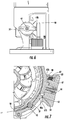
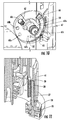
- FIGS. 18a, 18b The 0 degree position corresponding to the macro-adjustment position indicator 43a is shown in FIGS. 18a, 18b .
- the roller 54b In this position the roller 54b is offset from the zone 114a of the plate 110 so no spring force is exerted on the roller arrangement 54' or the door 40.
- the clamping cuff 32' defines a circumferential channel 32a for receiving the cam plate 110 as the wave spring arrangement 100 pushes against the knob 47 and cam plate 110.
- FIGS. 19a , 19b illustrate the initial contact between the roller 54b and the cam surface 114 , in particular at the zone 114b. In this position the cam plate 110 has been moved upwards into the knob just in contact with the wave spring arrangement 100. In one embodiment this contact occurs after about 20 degrees of rotation of the knob and before the knob is at the micro-adjustment position 43b.
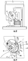
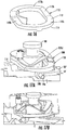
- FIGS. 20a, 20b show the orientation of the roller, cam plate and wave spring arrangement when the knob is rotated to the micro-adjustment position 43b.
- the roller 54b contacts the zone 114c of the cam plate 110 which pushes the cam plate further upward into the knob, thereby compressing the wave portions 101b, 101c between the cam plate and the knob.
- This compression results in a spring force against the roller arrangement 54' and door 40 to bring the bore halves 38 , 39 together about the threaded shaft 37 to thereby permit the fine height adjustment for the tool.
- this orientation occurs at about 40 degrees of rotation of the knob 47.
- FIGS. 21a, 21b show the roller 54b contacting the final zone 114e of the cam plate 110 when the knob has been rotated to the locking position 43c.
- the roller 54b moves along the transition zone 114d so that the spring force gradually increases.
- the wave spring arrangement 100 is at its greatest compression between the cam plate and knob so that the spring force is thus at its greatest to lock the threaded shaft 37 within the bore halves and thereby lock the vertical position of the tool. In one embodiment this orientation occurs at about 80 degrees of rotation of the knob 47.
- the wave spring arrangement 100 can have a free uncompressed height in the macro-adjustment position ( FIGS. 18a , 18b ) of about 0.300 in. (7.62 mm).
- the wave spring arrangement In the micro-adjustment position ( FIGS. 20a, 20b ) the wave spring arrangement can be compressed to a height of about 0.269 in. (6.832 mm) for a spring force of about 10 lbf.
- the spring In the locking position ( FIGS. 21a, 21b ) the spring is further compressed to a height of about 0.216 in. (5.48mm) for a clamping spring force of about 26 lbf.
- the cam plate 110 may be configured to translate uniformly upward as the knob 47 is rotated and the roller 54b bears against the successive zones 114b-114e.
- the cam plate 110 may include a fulcrum 116 , best shown in FIG. 20a , about which the cam plate pivots.
- the fulcrum 116 is generally opposite the transition zone 114d but it is understood that the cam plate 110 will pivot upward about the fulcrum as the roller contacts the transition zone 114b and continues through the remaining zones 114c-114e.
- the cam plate 110 may be pivotably fastened to the knob at the fulcrum 116 , such as by a pivot pin passing through the knob and fulcrum.
- the knob 47 includes a spring-biased cap 62 that engages one of three recesses 60a, 60b, 60c corresponding to the three functional positions 43a, 43b, 43c of the knob.
- the detent positioning feature for the knob can be incorporated into the cam plate.
- a cam plate 120 can be modified from the cam plate 110 to incorporate the detent feature.
- the cam plate 120 can include an upper surface 121 and cam surface 122 that can be the same as the upper and cam surfaces of the prior cam plate 110.
- the cam plate 120 includes three detent channels 125a, 125b, 125c defined in the inner circumferential surface 124 of the cam plate. These three channels are configured to receive a detent spring, such as the detent spring 130 shown in FIG. 23 .
- the detent spring 130 includes a base 131 that is fastened to a hub 140 defined on the clamping cuff 32.
- the knob is pivotably mounted on the hub 140 and the cam plate 120 is connected to the knob to rotate with the knob as described above.
- the detent spring 130 is thus held in a fixed position relative to the knob, cam plate and detent channels 125a, 125b, 125c.
- the detent spring 130 further includes a detent portion 132 that is configured to seat within any of the channels, such as the channel 125a depicted in FIG. 23 .
- the free end 133 of the spring rides along the hub 140 so that the spring can deflect as needed to release from a channel when the knob is rotated relative to the hub and detent spring.
- an adjustable pre-load may be applied to the cam plate in addition to the spring force applied to the plate by the wave spring arrangement 100.
- a cantilevered spring 150 may be mounted on a cam plate 110', 120' that has been modified to included support steps 152, 153 for supporting the opposite ends of the cantilevered spring 150.
- a set screw 155 supported in a modified knob 47' bears against the cantilevered spring 150 to push down on the spring. This downward force is translated to the cam plate 110', 120' through the support steps 152, 153 to apply a pre-load.
- the amount of pre-load can be adjusted by threading the set screw 155 into or out of the knob.
- FIGS. 25a, 25b show a further adjustable pre-load component incorporating a set screw 160 threaded into a bore 161 defined in the mounting screw 44 used to fasten the knob 47 to the housing.
- the set screw 160 bears against a washer 165 disposed concentrically about the hub 44a of the mounting screw and positioned between a shoulder 44b of the mounting screw 44 and a shoulder 166 of the knob.
- the set screw 160 can thus be used to adjust the pre-load on the wave spring arrangement 100.
- the force generating component operable to apply the force to the door is accomplished through a knob that is rotatably mounted to the clamping cuff.
- the actuator knob 47 may be mounted for movement relative to the clamping cuff other than in a rotary movement.
- the knob may be mounted to slide vertically or horizontally relative to the clamping cuff, with appropriate modification to the actuator surface 48, wave spring arrangement 100 , and cam plate 110 , for instance.
- the circumferential features of the force generating components may be arranged linearly so that the linear movement of the actuator knob produces the same force changes described above.
- the threaded shaft 37 of the height adjustment assembly 34 is integrated with a thumbwheel 35
- the thumbwheel can be replaced with another arrangement for rotating the threaded shaft, such as a gear train or lever arrangement.
- the force generating component may generate no force or only a minimal force on the door.
- the minimal force is not sufficient to permit threaded engagement of the threaded shaft to the half-bore of the bearing sleeve.
Landscapes
- Engineering & Computer Science (AREA)
- Mechanical Engineering (AREA)
- Life Sciences & Earth Sciences (AREA)
- Wood Science & Technology (AREA)
- Forests & Forestry (AREA)
- Lock And Its Accessories (AREA)
- Transmission Devices (AREA)
- Mechanical Operated Clutches (AREA)
- Closing And Opening Devices For Wings, And Checks For Wings (AREA)
Claims (12)
- Werkzeug, Folgendes umfassend:einen Werkzeugträger (12), der ein Elektrowerkzeug (10) in einstellbaren Höhen trägt, wobei das Elektrowerkzeug (10) einen länglichen Körper aufweist, der ein Arbeitswerkzeug trägt;eine Basis (31), die dazu ausgelegt ist, auf einer Arbeitsfläche aufzuliegen;eine Einspannmanschette (32), die mit der Basis (31) verbunden ist, wobei die Einspannmanschette (32) dazu ausgelegt ist, den länglichen Körper des Elektrowerkzeugs (10) dort hindurch in einstellbaren Höhen über der Arbeitsfläche aufzunehmen;einen Lagerflansch (50), der dem länglichen Körper des Elektrowerkzeugs (10) zugeordnet ist, wobei der Lagerflansch (50) mit der Einspannmanschette (32) in Gleiteingriff steht;wobei die Einspannmanschette (32) eine Öffnung definiert, wobei der Lagerflansch (50) durch die Öffnung hindurch zugänglich ist;eine Tür (40), die beweglich an der Einspannmanschette (32) montiert ist, um sich durch die Öffnung in Richtung des Lagerflanschs (50) zu bewegen;wobei die Tür (40) eine Halbbohrung (38) umfasst und der Lagerflansch (50) eine Halbbohrung (39) mit Gewinde umfasst, die zusammen eine Bohrung mit einem halben Gewinde ausbilden, wenn die Tür (40) direkt an den Lagerflansch (50) angrenzt;eine Gewindestange (37), die zwischen der Tür (40) und dem Lagerflansch (50) angeordnet ist und dazu ausgelegt ist, mit der Halbbohrung (39) mit Gewinde im Lagerflansch (50) verschraubt zu werden, wenn die Tür (40) und der Lagerflansch (50) direkt aneinander angrenzen, wobei die Halbbohrung (39) mit Gewinde derart ausgelegt ist, dass die Drehung der Gewindestange (37) die Höhe des länglichen Körpers des Elektrowerkzeugs (10) in Bezug zur Basis (31) einstellt; undeinen Aktor (42), um die Tür (40) und den Lagerflansch (50) selektiv in direkte Angrenzung zueinander zu bewegen, um die Bohrung mit dem halben Gewinde auszubilden, wobei der Aktor (42) Folgendes umfasst:einen Drehknopf (47), der beweglich auf der Einspannmanschette (32) montiert ist; undeine krafterzeugende Komponente, die dem Drehknopf (47) zugeordnet ist und in verschiedenen Positionen des Drehknopfs (47) in Bezug zur Einspannmanschette (32) betriebsfähig ist, um eine unterschiedliche Kraft auf die Tür (40) aufzuwenden und die Tür (40) in Richtung des Lagerflanschs (50) zu drücken, wobei die krafterzeugende Komponente eine Feder umfasst, wobei die Feder eine Wellenfeder (100) ist, wobei die krafterzeugende Komponente Folgendes umfasst:eine Rolle (54b), die drehbar an der Tür (40) gelagert wird; undeine Nockenplatte (110), die dem Drehknopf (47) zugeordnet und damit in Bezug zur Rolle (54b) beweglich ist, wobei die Nockenplatte (110) zwischen der Rolle (54b) und der Wellenfeder (100) angeordnet ist und die Wellenfeder (100) zwischen der Nockenplatte (110) und dem Drehknopf (47) angeordnet ist, wobei die Nockenplatte (110) eine Nockenfläche (114) aufweist, die dazu ausgelegt ist, die Wellenfeder (100) in Abhängigkeit von der Berührungsstelle zwischen der Rolle (54b) und der Nockenfläche (114) variabel zwischen der Nockenplatte (110) und dem Drehknopf (47) zusammenzudrücken.
- Werkzeug nach Anspruch 1, wobei die Tür (40) in eine Position vorgespannt ist, die nicht direkt an den Lagerflansch (50) angrenzt, sodass sich die Gewindestange (37) nicht in die Halbbohrung (39) mit Gewinde des Lagerflanschs (50) verschrauben kann.
- Werkzeug nach Anspruch 1, wobei die Tür (40) an einem Ende verschwenkbar an der Einspannmanschette (32) montiert ist und der Aktor (42) auf der Einspannmanschette (32) beweglich gelagert wird, um in ein Ende der Tür (40), das der Schwenklagerung entgegengesetzt ist, einzugreifen.
- Werkzeug nach Anspruch 1, wobei die Gewindestange (37) ein Rändelrad (35) umfasst, das außerhalb der Einspannmanschette (32) zugänglich ist, um die Gewindestange (37) manuell zu drehen.
- Werkzeug nach Anspruch 1, wobei die Gewindestange (37) in Eingriff mit der Halbbohrung (38) der Tür (40) drehbar in der Tür (40) gelagert wird.
- Werkzeug nach Anspruch 1, wobei die krafterzeugende Komponente dazu ausgelegt ist, in einer ersten Position keine Kraft auf die Tür (40) zu erzeugen, um es dem Körper des Elektrowerkzeugs (10) zu ermöglichen, sich innerhalb der Einspannmanschette (32) im Wesentlichen frei zu bewegen, in einer anderen, zweiten Position ausreichend Kraft zu erzeugen, um die Bohrung mit halbem Gewinde auszubilden und das Verschrauben der Gewindestange (37) mit der Halbbohrung (39) mit Gewinde des Lagerflanschs (50) zuzulassen, und in einer anderen, dritten Position ausreichend Kraft zu erzeugen, um die Drehung der Gewindestange (37) innerhalb der Bohrung mit halbem Gewinde einzuschränken, um dadurch das Elektrowerkzeug (10) auf einer Höhe über der Basis (31) zu halten.
- Werkzeug nach Anspruch 6, wobei die Einspannmanschette (32) und der Drehknopf (47) eine Rastfläche umfassen, um den Drehknopf (47) entsprechend der ersten, zweiten und dritten Position der krafterzeugenden Komponente in der ersten, zweiten oder dritten Position zu halten.
- Werkzeug nach Anspruch 7, ferner Markierungen umfassend, die die erste, zweite und dritte Position des Drehknopfs (47) anzeigen.
- Werkzeug nach Anspruch 1, wobei die Nockenfläche (114) der Nockenplatte (110) einen ersten Bereich umfasst, der von der Rolle (54b) versetzt ist, wenn sich der Drehknopf (47) in Bezug zur Rolle (54b) in einer ersten Position befindet.
- Werkzeug nach Anspruch 9, wobei die Nockenfläche (114) der Nockenplatte (110) mindestens zwei zusätzliche aufeinanderfolgende Bereiche umfasst, die mit der Rolle (54b) in Kontakt stehen, wenn sich der Drehknopf (47) in Bezug zur Rolle (54b) in mindestens zwei zusätzlichen, anderen Positionen befindet, in denen die Wellenfeder (100) schrittweise zusammengedrückt wird.
- Werkzeug nach Anspruch 10, wobei die Einspannmanschette (32) und der Drehknopf (47) eine Rastfläche umfassen, um den Drehknopf (47) in der ersten und/oder den mindestens zwei zusätzlichen Positionen zu halten, die der ersten und den zusätzlichen aufeinanderfolgenden Bereichen der Nockenfläche (114) der Nockenplatte (110) entsprechen.
- Werkzeug nach Anspruch 11, wobei die Rastfläche Folgendes umfasst:eine Nut, die jeweils der ersten und den mindestens zwei zusätzlichen Positionen des Drehknopfs (47) entspricht; undeine Rastfeder, die an der Einspannmanschette (32) montiert ist und einen Rastabschnitt (132) aufweist, der dazu ausgelegt ist, in die Nut einzugreifen.
Applications Claiming Priority (2)
| Application Number | Priority Date | Filing Date | Title |
|---|---|---|---|
| US201361920901P | 2013-12-26 | 2013-12-26 | |
| PCT/US2014/072126 WO2015100311A1 (en) | 2013-12-26 | 2014-12-23 | Base for a trim router |
Publications (3)
| Publication Number | Publication Date |
|---|---|
| EP3086896A1 EP3086896A1 (de) | 2016-11-02 |
| EP3086896A4 EP3086896A4 (de) | 2017-08-02 |
| EP3086896B1 true EP3086896B1 (de) | 2020-04-01 |
Family
ID=53479645
Family Applications (1)
| Application Number | Title | Priority Date | Filing Date |
|---|---|---|---|
| EP14875652.1A Active EP3086896B1 (de) | 2013-12-26 | 2014-12-23 | Handwerkzeugmaschine |
Country Status (4)
| Country | Link |
|---|---|
| US (1) | US10647019B2 (de) |
| EP (1) | EP3086896B1 (de) |
| CN (1) | CN106457420B (de) |
| WO (1) | WO2015100311A1 (de) |
Families Citing this family (8)
| Publication number | Priority date | Publication date | Assignee | Title |
|---|---|---|---|---|
| US10131042B2 (en) | 2013-10-21 | 2018-11-20 | Milwaukee Electric Tool Corporation | Adapter for power tool devices |
| DE102017205565B4 (de) * | 2017-03-31 | 2024-12-19 | Robert Bosch Gmbh | Handwerkzeugmaschine |
| US10556311B2 (en) * | 2017-04-04 | 2020-02-11 | Robert Bosch Gmbh | Lock device for power tool adjustment |
| CN108515584B (zh) * | 2018-04-11 | 2020-07-24 | 浙江纺织服装职业技术学院 | 一种室内装修用便携修边机 |
| CN212042789U (zh) | 2019-05-15 | 2020-12-01 | 米沃奇电动工具公司 | 刳刨机 |
| CN217669927U (zh) | 2021-12-20 | 2022-10-28 | 创科无线普通合伙 | 刨槽机 |
| CN119159136B (zh) * | 2024-11-20 | 2025-02-25 | 江苏东成工具科技有限公司 | 修边机的深度调整装置及修边机 |
| CN119795304A (zh) * | 2025-02-26 | 2025-04-11 | 北京金隅天坛家具股份有限公司 | 一种木质家具生产加工用修边设备 |
Family Cites Families (23)
| Publication number | Priority date | Publication date | Assignee | Title |
|---|---|---|---|---|
| US528074A (en) * | 1894-10-23 | John l | ||
| US2491543A (en) * | 1948-05-07 | 1949-12-20 | Alfonso Joseph | Release nut |
| US2631357A (en) * | 1950-09-13 | 1953-03-17 | Gobel Charles | Tool carrier and toolholder |
| US5088865A (en) * | 1991-02-28 | 1992-02-18 | Ryobi Motor Products Corp. | Depth of cut adjustment mechansm for a router |
| KR0172807B1 (ko) * | 1996-06-25 | 1999-02-18 | 이종수 | 절단기의 바이스 어셈블리 및 그 제조 방법 |
| CN2316872Y (zh) | 1997-10-31 | 1999-05-05 | 廖村淇 | 乐器座椅的高度调节机构 |
| US8087437B2 (en) * | 2000-08-11 | 2012-01-03 | Techtronic Power Tools Technology Limited | Router |
| DE60134437D1 (de) | 2000-08-11 | 2008-07-24 | Milwaukee Electric Tool Corp | Handfräsmaschine |
| US6599293B2 (en) * | 2001-07-16 | 2003-07-29 | Stryker Instruments | Delivery device for bone cement |
| US7073993B2 (en) * | 2002-10-15 | 2006-07-11 | Porter-Cable Corporation | Switch assembly |
| US7334614B2 (en) | 2002-10-15 | 2008-02-26 | Black & Decker Inc. | Depth adjustment mechanism |
| US7334613B2 (en) | 2002-10-15 | 2008-02-26 | Black & Decker Inc. | Router base securing mechanism |
| US7290575B2 (en) * | 2003-07-09 | 2007-11-06 | Credo Technology Corporation | Hybrid router |
| DE10359420A1 (de) | 2003-12-18 | 2005-07-28 | Robert Bosch Gmbh | Handwerkzeugmaschine |
| DE102004033801A1 (de) * | 2004-07-12 | 2006-02-16 | Robert Bosch Gmbh | Handwerkzeugmaschine |
| US7758274B2 (en) * | 2006-04-11 | 2010-07-20 | Warsaw Orthopedic, Inc. | Quick attachment apparatus for use in association with orthopedic instrumentation and tools |
| CN201009086Y (zh) | 2007-02-08 | 2008-01-23 | 南京德朔实业有限公司 | 一种可调高电动工具 |
| CN201195252Y (zh) | 2008-04-30 | 2009-02-18 | 王敏其 | 数控机床的凸轮锁紧定位装置 |
| CN201677304U (zh) | 2008-09-11 | 2010-12-22 | 创科电动工具科技有限公司 | 刳刨机 |
| US8517366B2 (en) * | 2008-11-26 | 2013-08-27 | Seber Design Group, Inc. | Quick release bench vise system |
| EP2396152B1 (de) * | 2009-02-13 | 2017-08-09 | Black & Decker, Inc. | Router |
| DE102012223908B4 (de) * | 2012-12-20 | 2021-02-11 | Robert Bosch Gmbh | Handwerkzeugmaschine mit einer Abstützeinrichtung |
| USD740097S1 (en) * | 2014-01-17 | 2015-10-06 | Robert Bosch Gmbh | Power tool |
-
2014
- 2014-12-23 WO PCT/US2014/072126 patent/WO2015100311A1/en not_active Ceased
- 2014-12-23 US US15/106,125 patent/US10647019B2/en active Active
- 2014-12-23 EP EP14875652.1A patent/EP3086896B1/de active Active
- 2014-12-23 CN CN201480070971.1A patent/CN106457420B/zh active Active
Non-Patent Citations (1)
| Title |
|---|
| None * |
Also Published As
| Publication number | Publication date |
|---|---|
| EP3086896A4 (de) | 2017-08-02 |
| CN106457420A (zh) | 2017-02-22 |
| CN106457420B (zh) | 2019-10-08 |
| WO2015100311A1 (en) | 2015-07-02 |
| EP3086896A1 (de) | 2016-11-02 |
| US10647019B2 (en) | 2020-05-12 |
| US20160318204A1 (en) | 2016-11-03 |
Similar Documents
| Publication | Publication Date | Title |
|---|---|---|
| EP3086896B1 (de) | Handwerkzeugmaschine | |
| US7661763B2 (en) | Chair armrest having a height adjustable function | |
| US20150351539A1 (en) | Acutating drive for moving a moveable furniture part | |
| US7302760B2 (en) | Folding knife with dual-action piston | |
| TWI694931B (zh) | 印章 | |
| US7011371B1 (en) | Armrest assembly having a height adjustable function | |
| US8123710B2 (en) | Limiting connector for knee brace | |
| US8052586B2 (en) | Ladder barrel with cam lock | |
| US20040158991A1 (en) | Safety for a folding knife | |
| JP5336395B2 (ja) | スタンプ装置 | |
| US20100299934A1 (en) | Folding knife | |
| US9335782B2 (en) | Ratchet mechanism including lockable pinion assembly | |
| JP5653601B2 (ja) | 肘掛け装置及びこれを備えた椅子 | |
| DE102006036636B4 (de) | Rasteinrichtung für ein Bedienelement in einem Kraftfahrzeug | |
| US9291178B2 (en) | Bracket assembly and retaining device for collapsible stand | |
| JP2018111958A (ja) | シャワーヘッド用フック装置 | |
| US9352481B2 (en) | Cutting device | |
| US10921576B2 (en) | Adjusting turret for a long-range optical device | |
| CN114838136A (zh) | 按压式可调减压阀 | |
| EP4173684B1 (de) | Spielsteuerung mit einstellbarer abzugslänge | |
| CN113454366A (zh) | 驱动装置以及医疗用泵 | |
| CN217633869U (zh) | 按压式可调减压阀 | |
| JP2006021553A (ja) | チルト式ステアリングコラム装置 | |
| US6899312B2 (en) | Pressure relief valve for flowing media | |
| US20250290739A1 (en) | Actuator-Type Combination Square |
Legal Events
| Date | Code | Title | Description |
|---|---|---|---|
| PUAI | Public reference made under article 153(3) epc to a published international application that has entered the european phase |
Free format text: ORIGINAL CODE: 0009012 |
|
| 17P | Request for examination filed |
Effective date: 20160726 |
|
| AK | Designated contracting states |
Kind code of ref document: A1 Designated state(s): AL AT BE BG CH CY CZ DE DK EE ES FI FR GB GR HR HU IE IS IT LI LT LU LV MC MK MT NL NO PL PT RO RS SE SI SK SM TR |
|
| AX | Request for extension of the european patent |
Extension state: BA ME |
|
| DAX | Request for extension of the european patent (deleted) | ||
| REG | Reference to a national code |
Ref country code: DE Ref legal event code: R079 Ref document number: 602014063329 Country of ref document: DE Free format text: PREVIOUS MAIN CLASS: B23C0001200000 Ipc: B27C0005100000 |
|
| A4 | Supplementary search report drawn up and despatched |
Effective date: 20170630 |
|
| RIC1 | Information provided on ipc code assigned before grant |
Ipc: B27C 5/10 20060101AFI20170626BHEP Ipc: B23Q 16/02 20060101ALI20170626BHEP Ipc: B23C 1/20 20060101ALI20170626BHEP Ipc: B25F 5/02 20060101ALI20170626BHEP |
|
| STAA | Information on the status of an ep patent application or granted ep patent |
Free format text: STATUS: EXAMINATION IS IN PROGRESS |
|
| 17Q | First examination report despatched |
Effective date: 20180516 |
|
| GRAP | Despatch of communication of intention to grant a patent |
Free format text: ORIGINAL CODE: EPIDOSNIGR1 |
|
| STAA | Information on the status of an ep patent application or granted ep patent |
Free format text: STATUS: GRANT OF PATENT IS INTENDED |
|
| INTG | Intention to grant announced |
Effective date: 20191127 |
|
| GRAS | Grant fee paid |
Free format text: ORIGINAL CODE: EPIDOSNIGR3 |
|
| GRAA | (expected) grant |
Free format text: ORIGINAL CODE: 0009210 |
|
| STAA | Information on the status of an ep patent application or granted ep patent |
Free format text: STATUS: THE PATENT HAS BEEN GRANTED |
|
| AK | Designated contracting states |
Kind code of ref document: B1 Designated state(s): AL AT BE BG CH CY CZ DE DK EE ES FI FR GB GR HR HU IE IS IT LI LT LU LV MC MK MT NL NO PL PT RO RS SE SI SK SM TR |
|
| REG | Reference to a national code |
Ref country code: GB Ref legal event code: FG4D |
|
| REG | Reference to a national code |
Ref country code: AT Ref legal event code: REF Ref document number: 1250795 Country of ref document: AT Kind code of ref document: T Effective date: 20200415 Ref country code: CH Ref legal event code: EP |
|
| REG | Reference to a national code |
Ref country code: DE Ref legal event code: R096 Ref document number: 602014063329 Country of ref document: DE |
|
| RAP2 | Party data changed (patent owner data changed or rights of a patent transferred) |
Owner name: ROBERT BOSCH GMBH |
|
| REG | Reference to a national code |
Ref country code: IE Ref legal event code: FG4D |
|
| PG25 | Lapsed in a contracting state [announced via postgrant information from national office to epo] |
Ref country code: BG Free format text: LAPSE BECAUSE OF FAILURE TO SUBMIT A TRANSLATION OF THE DESCRIPTION OR TO PAY THE FEE WITHIN THE PRESCRIBED TIME-LIMIT Effective date: 20200701 |
|
| REG | Reference to a national code |
Ref country code: NL Ref legal event code: MP Effective date: 20200401 |
|
| REG | Reference to a national code |
Ref country code: LT Ref legal event code: MG4D |
|
| PG25 | Lapsed in a contracting state [announced via postgrant information from national office to epo] |
Ref country code: FI Free format text: LAPSE BECAUSE OF FAILURE TO SUBMIT A TRANSLATION OF THE DESCRIPTION OR TO PAY THE FEE WITHIN THE PRESCRIBED TIME-LIMIT Effective date: 20200401 Ref country code: NO Free format text: LAPSE BECAUSE OF FAILURE TO SUBMIT A TRANSLATION OF THE DESCRIPTION OR TO PAY THE FEE WITHIN THE PRESCRIBED TIME-LIMIT Effective date: 20200701 Ref country code: GR Free format text: LAPSE BECAUSE OF FAILURE TO SUBMIT A TRANSLATION OF THE DESCRIPTION OR TO PAY THE FEE WITHIN THE PRESCRIBED TIME-LIMIT Effective date: 20200702 Ref country code: IS Free format text: LAPSE BECAUSE OF FAILURE TO SUBMIT A TRANSLATION OF THE DESCRIPTION OR TO PAY THE FEE WITHIN THE PRESCRIBED TIME-LIMIT Effective date: 20200801 Ref country code: NL Free format text: LAPSE BECAUSE OF FAILURE TO SUBMIT A TRANSLATION OF THE DESCRIPTION OR TO PAY THE FEE WITHIN THE PRESCRIBED TIME-LIMIT Effective date: 20200401 Ref country code: CZ Free format text: LAPSE BECAUSE OF FAILURE TO SUBMIT A TRANSLATION OF THE DESCRIPTION OR TO PAY THE FEE WITHIN THE PRESCRIBED TIME-LIMIT Effective date: 20200401 Ref country code: LT Free format text: LAPSE BECAUSE OF FAILURE TO SUBMIT A TRANSLATION OF THE DESCRIPTION OR TO PAY THE FEE WITHIN THE PRESCRIBED TIME-LIMIT Effective date: 20200401 Ref country code: PT Free format text: LAPSE BECAUSE OF FAILURE TO SUBMIT A TRANSLATION OF THE DESCRIPTION OR TO PAY THE FEE WITHIN THE PRESCRIBED TIME-LIMIT Effective date: 20200817 Ref country code: SE Free format text: LAPSE BECAUSE OF FAILURE TO SUBMIT A TRANSLATION OF THE DESCRIPTION OR TO PAY THE FEE WITHIN THE PRESCRIBED TIME-LIMIT Effective date: 20200401 |
|
| REG | Reference to a national code |
Ref country code: AT Ref legal event code: MK05 Ref document number: 1250795 Country of ref document: AT Kind code of ref document: T Effective date: 20200401 |
|
| PG25 | Lapsed in a contracting state [announced via postgrant information from national office to epo] |
Ref country code: RS Free format text: LAPSE BECAUSE OF FAILURE TO SUBMIT A TRANSLATION OF THE DESCRIPTION OR TO PAY THE FEE WITHIN THE PRESCRIBED TIME-LIMIT Effective date: 20200401 Ref country code: HR Free format text: LAPSE BECAUSE OF FAILURE TO SUBMIT A TRANSLATION OF THE DESCRIPTION OR TO PAY THE FEE WITHIN THE PRESCRIBED TIME-LIMIT Effective date: 20200401 Ref country code: LV Free format text: LAPSE BECAUSE OF FAILURE TO SUBMIT A TRANSLATION OF THE DESCRIPTION OR TO PAY THE FEE WITHIN THE PRESCRIBED TIME-LIMIT Effective date: 20200401 |
|
| PG25 | Lapsed in a contracting state [announced via postgrant information from national office to epo] |
Ref country code: AL Free format text: LAPSE BECAUSE OF FAILURE TO SUBMIT A TRANSLATION OF THE DESCRIPTION OR TO PAY THE FEE WITHIN THE PRESCRIBED TIME-LIMIT Effective date: 20200401 |
|
| REG | Reference to a national code |
Ref country code: DE Ref legal event code: R097 Ref document number: 602014063329 Country of ref document: DE |
|
| PG25 | Lapsed in a contracting state [announced via postgrant information from national office to epo] |
Ref country code: DK Free format text: LAPSE BECAUSE OF FAILURE TO SUBMIT A TRANSLATION OF THE DESCRIPTION OR TO PAY THE FEE WITHIN THE PRESCRIBED TIME-LIMIT Effective date: 20200401 Ref country code: EE Free format text: LAPSE BECAUSE OF FAILURE TO SUBMIT A TRANSLATION OF THE DESCRIPTION OR TO PAY THE FEE WITHIN THE PRESCRIBED TIME-LIMIT Effective date: 20200401 Ref country code: SM Free format text: LAPSE BECAUSE OF FAILURE TO SUBMIT A TRANSLATION OF THE DESCRIPTION OR TO PAY THE FEE WITHIN THE PRESCRIBED TIME-LIMIT Effective date: 20200401 Ref country code: AT Free format text: LAPSE BECAUSE OF FAILURE TO SUBMIT A TRANSLATION OF THE DESCRIPTION OR TO PAY THE FEE WITHIN THE PRESCRIBED TIME-LIMIT Effective date: 20200401 Ref country code: ES Free format text: LAPSE BECAUSE OF FAILURE TO SUBMIT A TRANSLATION OF THE DESCRIPTION OR TO PAY THE FEE WITHIN THE PRESCRIBED TIME-LIMIT Effective date: 20200401 Ref country code: IT Free format text: LAPSE BECAUSE OF FAILURE TO SUBMIT A TRANSLATION OF THE DESCRIPTION OR TO PAY THE FEE WITHIN THE PRESCRIBED TIME-LIMIT Effective date: 20200401 Ref country code: RO Free format text: LAPSE BECAUSE OF FAILURE TO SUBMIT A TRANSLATION OF THE DESCRIPTION OR TO PAY THE FEE WITHIN THE PRESCRIBED TIME-LIMIT Effective date: 20200401 |
|
| PLBE | No opposition filed within time limit |
Free format text: ORIGINAL CODE: 0009261 |
|
| STAA | Information on the status of an ep patent application or granted ep patent |
Free format text: STATUS: NO OPPOSITION FILED WITHIN TIME LIMIT |
|
| PG25 | Lapsed in a contracting state [announced via postgrant information from national office to epo] |
Ref country code: PL Free format text: LAPSE BECAUSE OF FAILURE TO SUBMIT A TRANSLATION OF THE DESCRIPTION OR TO PAY THE FEE WITHIN THE PRESCRIBED TIME-LIMIT Effective date: 20200401 Ref country code: SK Free format text: LAPSE BECAUSE OF FAILURE TO SUBMIT A TRANSLATION OF THE DESCRIPTION OR TO PAY THE FEE WITHIN THE PRESCRIBED TIME-LIMIT Effective date: 20200401 |
|
| 26N | No opposition filed |
Effective date: 20210112 |
|
| PG25 | Lapsed in a contracting state [announced via postgrant information from national office to epo] |
Ref country code: SI Free format text: LAPSE BECAUSE OF FAILURE TO SUBMIT A TRANSLATION OF THE DESCRIPTION OR TO PAY THE FEE WITHIN THE PRESCRIBED TIME-LIMIT Effective date: 20200401 |
|
| REG | Reference to a national code |
Ref country code: CH Ref legal event code: PL |
|
| GBPC | Gb: european patent ceased through non-payment of renewal fee |
Effective date: 20201223 |
|
| PG25 | Lapsed in a contracting state [announced via postgrant information from national office to epo] |
Ref country code: MC Free format text: LAPSE BECAUSE OF FAILURE TO SUBMIT A TRANSLATION OF THE DESCRIPTION OR TO PAY THE FEE WITHIN THE PRESCRIBED TIME-LIMIT Effective date: 20200401 |
|
| REG | Reference to a national code |
Ref country code: BE Ref legal event code: MM Effective date: 20201231 |
|
| PG25 | Lapsed in a contracting state [announced via postgrant information from national office to epo] |
Ref country code: IE Free format text: LAPSE BECAUSE OF NON-PAYMENT OF DUE FEES Effective date: 20201223 Ref country code: LU Free format text: LAPSE BECAUSE OF NON-PAYMENT OF DUE FEES Effective date: 20201223 Ref country code: FR Free format text: LAPSE BECAUSE OF NON-PAYMENT OF DUE FEES Effective date: 20201231 |
|
| PG25 | Lapsed in a contracting state [announced via postgrant information from national office to epo] |
Ref country code: LI Free format text: LAPSE BECAUSE OF NON-PAYMENT OF DUE FEES Effective date: 20201231 Ref country code: GB Free format text: LAPSE BECAUSE OF NON-PAYMENT OF DUE FEES Effective date: 20201223 Ref country code: CH Free format text: LAPSE BECAUSE OF NON-PAYMENT OF DUE FEES Effective date: 20201231 |
|
| PG25 | Lapsed in a contracting state [announced via postgrant information from national office to epo] |
Ref country code: TR Free format text: LAPSE BECAUSE OF FAILURE TO SUBMIT A TRANSLATION OF THE DESCRIPTION OR TO PAY THE FEE WITHIN THE PRESCRIBED TIME-LIMIT Effective date: 20200401 Ref country code: MT Free format text: LAPSE BECAUSE OF FAILURE TO SUBMIT A TRANSLATION OF THE DESCRIPTION OR TO PAY THE FEE WITHIN THE PRESCRIBED TIME-LIMIT Effective date: 20200401 Ref country code: CY Free format text: LAPSE BECAUSE OF FAILURE TO SUBMIT A TRANSLATION OF THE DESCRIPTION OR TO PAY THE FEE WITHIN THE PRESCRIBED TIME-LIMIT Effective date: 20200401 |
|
| PG25 | Lapsed in a contracting state [announced via postgrant information from national office to epo] |
Ref country code: MK Free format text: LAPSE BECAUSE OF FAILURE TO SUBMIT A TRANSLATION OF THE DESCRIPTION OR TO PAY THE FEE WITHIN THE PRESCRIBED TIME-LIMIT Effective date: 20200401 |
|
| PG25 | Lapsed in a contracting state [announced via postgrant information from national office to epo] |
Ref country code: BE Free format text: LAPSE BECAUSE OF NON-PAYMENT OF DUE FEES Effective date: 20201231 |
|
| PGFP | Annual fee paid to national office [announced via postgrant information from national office to epo] |
Ref country code: DE Payment date: 20260223 Year of fee payment: 12 |