EP3087010B1 - Behälterverschluss, behälteranordnung und verfahren zur verwendung davon - Google Patents
Behälterverschluss, behälteranordnung und verfahren zur verwendung davon Download PDFInfo
- Publication number
- EP3087010B1 EP3087010B1 EP14874425.3A EP14874425A EP3087010B1 EP 3087010 B1 EP3087010 B1 EP 3087010B1 EP 14874425 A EP14874425 A EP 14874425A EP 3087010 B1 EP3087010 B1 EP 3087010B1
- Authority
- EP
- European Patent Office
- Prior art keywords
- container
- syringe
- fluid
- end wall
- container closure
- Prior art date
- Legal status (The legal status is an assumption and is not a legal conclusion. Google has not performed a legal analysis and makes no representation as to the accuracy of the status listed.)
- Active
Links
Images










Classifications
-
- A—HUMAN NECESSITIES
- A61—MEDICAL OR VETERINARY SCIENCE; HYGIENE
- A61M—DEVICES FOR INTRODUCING MEDIA INTO, OR ONTO, THE BODY; DEVICES FOR TRANSDUCING BODY MEDIA OR FOR TAKING MEDIA FROM THE BODY; DEVICES FOR PRODUCING OR ENDING SLEEP OR STUPOR
- A61M5/00—Devices for bringing media into the body in a subcutaneous, intra-vascular or intramuscular way; Accessories therefor, e.g. filling or cleaning devices, arm-rests
- A61M5/178—Syringes
- A61M5/1782—Devices aiding filling of syringes in situ
-
- A—HUMAN NECESSITIES
- A61—MEDICAL OR VETERINARY SCIENCE; HYGIENE
- A61M—DEVICES FOR INTRODUCING MEDIA INTO, OR ONTO, THE BODY; DEVICES FOR TRANSDUCING BODY MEDIA OR FOR TAKING MEDIA FROM THE BODY; DEVICES FOR PRODUCING OR ENDING SLEEP OR STUPOR
- A61M5/00—Devices for bringing media into the body in a subcutaneous, intra-vascular or intramuscular way; Accessories therefor, e.g. filling or cleaning devices, arm-rests
- A61M5/178—Syringes
- A61M5/31—Details
- A61M5/32—Needles; Details of needles pertaining to their connection with syringe or hub; Accessories for bringing the needle into, or holding the needle on, the body; Devices for protection of needles
- A61M5/3205—Apparatus for removing or disposing of used needles or syringes, e.g. containers; Means for protection against accidental injuries from used needles
-
- B—PERFORMING OPERATIONS; TRANSPORTING
- B01—PHYSICAL OR CHEMICAL PROCESSES OR APPARATUS IN GENERAL
- B01L—CHEMICAL OR PHYSICAL LABORATORY APPARATUS FOR GENERAL USE
- B01L3/00—Containers or dishes for laboratory use, e.g. laboratory glassware; Droppers
- B01L3/50—Containers for the purpose of retaining a material to be analysed, e.g. test tubes
- B01L3/502—Containers for the purpose of retaining a material to be analysed, e.g. test tubes with fluid transport, e.g. in multi-compartment structures
-
- B—PERFORMING OPERATIONS; TRANSPORTING
- B01—PHYSICAL OR CHEMICAL PROCESSES OR APPARATUS IN GENERAL
- B01L—CHEMICAL OR PHYSICAL LABORATORY APPARATUS FOR GENERAL USE
- B01L3/00—Containers or dishes for laboratory use, e.g. laboratory glassware; Droppers
- B01L3/50—Containers for the purpose of retaining a material to be analysed, e.g. test tubes
- B01L3/508—Rigid containers without fluid transport within
-
- B—PERFORMING OPERATIONS; TRANSPORTING
- B01—PHYSICAL OR CHEMICAL PROCESSES OR APPARATUS IN GENERAL
- B01L—CHEMICAL OR PHYSICAL LABORATORY APPARATUS FOR GENERAL USE
- B01L3/00—Containers or dishes for laboratory use, e.g. laboratory glassware; Droppers
- B01L3/50—Containers for the purpose of retaining a material to be analysed, e.g. test tubes
- B01L3/508—Rigid containers without fluid transport within
- B01L3/5082—Test tubes per se
- B01L3/50825—Closing or opening means, corks, bungs
-
- B—PERFORMING OPERATIONS; TRANSPORTING
- B65—CONVEYING; PACKING; STORING; HANDLING THIN OR FILAMENTARY MATERIAL
- B65D—CONTAINERS FOR STORAGE OR TRANSPORT OF ARTICLES OR MATERIALS, e.g. BAGS, BARRELS, BOTTLES, BOXES, CANS, CARTONS, CRATES, DRUMS, JARS, TANKS, HOPPERS, FORWARDING CONTAINERS; ACCESSORIES, CLOSURES, OR FITTINGS THEREFOR; PACKAGING ELEMENTS; PACKAGES
- B65D51/00—Closures not otherwise provided for
- B65D51/002—Closures to be pierced by an extracting-device for the contents and fixed on the container by separate retaining means
-
- B—PERFORMING OPERATIONS; TRANSPORTING
- B65—CONVEYING; PACKING; STORING; HANDLING THIN OR FILAMENTARY MATERIAL
- B65D—CONTAINERS FOR STORAGE OR TRANSPORT OF ARTICLES OR MATERIALS, e.g. BAGS, BARRELS, BOTTLES, BOXES, CANS, CARTONS, CRATES, DRUMS, JARS, TANKS, HOPPERS, FORWARDING CONTAINERS; ACCESSORIES, CLOSURES, OR FITTINGS THEREFOR; PACKAGING ELEMENTS; PACKAGES
- B65D51/00—Closures not otherwise provided for
- B65D51/24—Closures not otherwise provided for combined or co-operating with auxiliary devices for non-closing purposes
- B65D51/28—Closures not otherwise provided for combined or co-operating with auxiliary devices for non-closing purposes with auxiliary containers for additional articles or materials
- B65D51/2807—Closures not otherwise provided for combined or co-operating with auxiliary devices for non-closing purposes with auxiliary containers for additional articles or materials the closure presenting means for placing the additional articles or materials in contact with the main contents by acting on a part of the closure without removing the closure, e.g. by pushing down, pulling up, rotating or turning a part of the closure, or upon initial opening of the container
-
- A—HUMAN NECESSITIES
- A61—MEDICAL OR VETERINARY SCIENCE; HYGIENE
- A61M—DEVICES FOR INTRODUCING MEDIA INTO, OR ONTO, THE BODY; DEVICES FOR TRANSDUCING BODY MEDIA OR FOR TAKING MEDIA FROM THE BODY; DEVICES FOR PRODUCING OR ENDING SLEEP OR STUPOR
- A61M5/00—Devices for bringing media into the body in a subcutaneous, intra-vascular or intramuscular way; Accessories therefor, e.g. filling or cleaning devices, arm-rests
- A61M5/008—Racks for supporting syringes or needles
-
- A—HUMAN NECESSITIES
- A61—MEDICAL OR VETERINARY SCIENCE; HYGIENE
- A61M—DEVICES FOR INTRODUCING MEDIA INTO, OR ONTO, THE BODY; DEVICES FOR TRANSDUCING BODY MEDIA OR FOR TAKING MEDIA FROM THE BODY; DEVICES FOR PRODUCING OR ENDING SLEEP OR STUPOR
- A61M5/00—Devices for bringing media into the body in a subcutaneous, intra-vascular or intramuscular way; Accessories therefor, e.g. filling or cleaning devices, arm-rests
- A61M5/178—Syringes
- A61M5/31—Details
- A61M5/32—Needles; Details of needles pertaining to their connection with syringe or hub; Accessories for bringing the needle into, or holding the needle on, the body; Devices for protection of needles
- A61M5/3205—Apparatus for removing or disposing of used needles or syringes, e.g. containers; Means for protection against accidental injuries from used needles
- A61M5/321—Means for protection against accidental injuries by used needles
- A61M5/3213—Caps placed axially onto the needle, e.g. equipped with finger protection guards
-
- B—PERFORMING OPERATIONS; TRANSPORTING
- B01—PHYSICAL OR CHEMICAL PROCESSES OR APPARATUS IN GENERAL
- B01L—CHEMICAL OR PHYSICAL LABORATORY APPARATUS FOR GENERAL USE
- B01L2200/00—Solutions for specific problems relating to chemical or physical laboratory apparatus
- B01L2200/02—Adapting objects or devices to another
- B01L2200/025—Align devices or objects to ensure defined positions relative to each other
-
- B—PERFORMING OPERATIONS; TRANSPORTING
- B01—PHYSICAL OR CHEMICAL PROCESSES OR APPARATUS IN GENERAL
- B01L—CHEMICAL OR PHYSICAL LABORATORY APPARATUS FOR GENERAL USE
- B01L2200/00—Solutions for specific problems relating to chemical or physical laboratory apparatus
- B01L2200/02—Adapting objects or devices to another
- B01L2200/026—Fluid interfacing between devices or objects, e.g. connectors, inlet details
-
- B—PERFORMING OPERATIONS; TRANSPORTING
- B01—PHYSICAL OR CHEMICAL PROCESSES OR APPARATUS IN GENERAL
- B01L—CHEMICAL OR PHYSICAL LABORATORY APPARATUS FOR GENERAL USE
- B01L2200/00—Solutions for specific problems relating to chemical or physical laboratory apparatus
- B01L2200/14—Process control and prevention of errors
- B01L2200/141—Preventing contamination, tampering
-
- B—PERFORMING OPERATIONS; TRANSPORTING
- B01—PHYSICAL OR CHEMICAL PROCESSES OR APPARATUS IN GENERAL
- B01L—CHEMICAL OR PHYSICAL LABORATORY APPARATUS FOR GENERAL USE
- B01L2300/00—Additional constructional details
- B01L2300/02—Identification, exchange or storage of information
- B01L2300/021—Identification, e.g. bar codes
-
- B—PERFORMING OPERATIONS; TRANSPORTING
- B01—PHYSICAL OR CHEMICAL PROCESSES OR APPARATUS IN GENERAL
- B01L—CHEMICAL OR PHYSICAL LABORATORY APPARATUS FOR GENERAL USE
- B01L2300/00—Additional constructional details
- B01L2300/04—Closures and closing means
- B01L2300/041—Connecting closures to device or container
- B01L2300/042—Caps; Plugs
-
- B—PERFORMING OPERATIONS; TRANSPORTING
- B01—PHYSICAL OR CHEMICAL PROCESSES OR APPARATUS IN GENERAL
- B01L—CHEMICAL OR PHYSICAL LABORATORY APPARATUS FOR GENERAL USE
- B01L2300/00—Additional constructional details
- B01L2300/04—Closures and closing means
- B01L2300/041—Connecting closures to device or container
- B01L2300/043—Hinged closures
-
- B—PERFORMING OPERATIONS; TRANSPORTING
- B01—PHYSICAL OR CHEMICAL PROCESSES OR APPARATUS IN GENERAL
- B01L—CHEMICAL OR PHYSICAL LABORATORY APPARATUS FOR GENERAL USE
- B01L2300/00—Additional constructional details
- B01L2300/04—Closures and closing means
- B01L2300/041—Connecting closures to device or container
- B01L2300/044—Connecting closures to device or container pierceable, e.g. films, membranes
-
- B—PERFORMING OPERATIONS; TRANSPORTING
- B01—PHYSICAL OR CHEMICAL PROCESSES OR APPARATUS IN GENERAL
- B01L—CHEMICAL OR PHYSICAL LABORATORY APPARATUS FOR GENERAL USE
- B01L2300/00—Additional constructional details
- B01L2300/04—Closures and closing means
- B01L2300/046—Function or devices integrated in the closure
-
- B—PERFORMING OPERATIONS; TRANSPORTING
- B01—PHYSICAL OR CHEMICAL PROCESSES OR APPARATUS IN GENERAL
- B01L—CHEMICAL OR PHYSICAL LABORATORY APPARATUS FOR GENERAL USE
- B01L2300/00—Additional constructional details
- B01L2300/08—Geometry, shape and general structure
- B01L2300/0803—Disc shape
-
- B—PERFORMING OPERATIONS; TRANSPORTING
- B01—PHYSICAL OR CHEMICAL PROCESSES OR APPARATUS IN GENERAL
- B01L—CHEMICAL OR PHYSICAL LABORATORY APPARATUS FOR GENERAL USE
- B01L2300/00—Additional constructional details
- B01L2300/08—Geometry, shape and general structure
- B01L2300/0832—Geometry, shape and general structure cylindrical, tube shaped
-
- B—PERFORMING OPERATIONS; TRANSPORTING
- B01—PHYSICAL OR CHEMICAL PROCESSES OR APPARATUS IN GENERAL
- B01L—CHEMICAL OR PHYSICAL LABORATORY APPARATUS FOR GENERAL USE
- B01L2300/00—Additional constructional details
- B01L2300/08—Geometry, shape and general structure
- B01L2300/0848—Specific forms of parts of containers
-
- B—PERFORMING OPERATIONS; TRANSPORTING
- B01—PHYSICAL OR CHEMICAL PROCESSES OR APPARATUS IN GENERAL
- B01L—CHEMICAL OR PHYSICAL LABORATORY APPARATUS FOR GENERAL USE
- B01L2300/00—Additional constructional details
- B01L2300/08—Geometry, shape and general structure
- B01L2300/0848—Specific forms of parts of containers
- B01L2300/0851—Bottom walls
-
- B—PERFORMING OPERATIONS; TRANSPORTING
- B01—PHYSICAL OR CHEMICAL PROCESSES OR APPARATUS IN GENERAL
- B01L—CHEMICAL OR PHYSICAL LABORATORY APPARATUS FOR GENERAL USE
- B01L2300/00—Additional constructional details
- B01L2300/08—Geometry, shape and general structure
- B01L2300/0848—Specific forms of parts of containers
- B01L2300/0858—Side walls
-
- B—PERFORMING OPERATIONS; TRANSPORTING
- B01—PHYSICAL OR CHEMICAL PROCESSES OR APPARATUS IN GENERAL
- B01L—CHEMICAL OR PHYSICAL LABORATORY APPARATUS FOR GENERAL USE
- B01L2300/00—Additional constructional details
- B01L2300/12—Specific details about materials
Definitions
- the disclosure relates to a container closure, a container assembly and a method for utilizing the same.
- Container closures and container assemblies are known in the art. Improvements to container closures and container assemblies are sought in order to advance the art.
- WO 2012/170813 , WO2013/148881 , and WO92/18844 disclose containers with closures including syringe engaging portions.
- One aspect of the disclosure provides a portion of a container assembly according to claim 1.
- the syringe-engaging portion is a syringe-receiving bore.
- the syringe-receiving bore is sized for receiving a distal end of a syringe.
- the syringe-receiving bore is formed in the outer surface of the end wall.
- the syringe-receiving bore is aligned with a central axis extending through the container closure.
- the syringe-receiving bore is formed in the outer surface of the side wall.
- the syringe-receiving bore is arranged substantially perpendicularly with respect to a central axis extending through the container closure.
- the fluid-drawing member includes a radial segment and an axial segment.
- the radial segment is integral with and extends in a radial direction toward the central axis from the inner surface of the side wall of the container closure.
- the radial segment is connected to the axial segment that is aligned with the central axis.
- the syringe-engaging portion is a substantially cylindrical tube-shaped member extending away from the outer surface of the end wall of the container closure.
- the substantially cylindrical tube-shaped member includes an outer threaded surface that is sized for receiving an inner threaded surface portion of a syringe.
- the substantially cylindrical tube-shaped member is recessed within a bore formed in the outer surface of the end wall of the container closure.
- the substantially cylindrical tube-shaped member is aligned with a central axis extending through the container closure.
- At least a portion of the fluid-flow passage is aligned with an axial center of the fluid-drawing member.
- the container closure also includes a disk-shaped member including a slit.
- the disk-shaped member is disposed upon and supported by one or more of a shoulder surface and an axial wall surface defining the syringe-engaging portion.
- the disk-shaped member is secured to one or more of the shoulder surface and the axial wall surface by an adhesive connection.
- the disk-shaped member is secured to one or more of the shoulder surface and the axial wall surface by a friction-fit connection.
- the disk-shaped member includes a foam or rubber material.
- the container closure also includes a pair of spaced-apart cover-retaining members extending from the outer surface of the end wall of the container closure.
- the pair of spaced-apart cover-retaining members includes a first cover-retaining member and a second cover-retaining member.
- the container closure also includes a cover member that is selectively disposed upon and supported by outer surface of the end wall of the container closure. The cover member is selectively retained to the container closure by the pair of spaced-apart cover-retaining members.
- the cover member isolates the syringe-engaging portion from surrounding atmosphere when the cover member that is selectively disposed upon and supported by outer surface of the end wall of the container closure.
- each cover-retaining member of the pair of cover-retaining members includes an axial surface portion and a radial surface portion.
- the axial surface portion of the first cover-retaining member is spaced apart from the axial surface portion of the second cover-retaining member to define a width gap having a width dimension.
- the radial surface portion of each of the first cover-retaining member and the second cover-retaining member is spaced apart from the outer surface of the end wall of the container closure to define a height gap having a height dimension.
- the cover member includes a width dimension extending between opposite side surfaces of the cover member.
- the cover member also includes a height dimension extending between a lower surface and an upper surface of the cover member.
- the width dimension of the cover member is approximately equal to but slightly less than the width dimension of the gap extending between the axial surface portions of the first cover-retaining member and the second cover-retaining member.
- the height dimension of the cover member is approximately equal to but slightly less than the height dimension of the gap extending between the radial surface portion of each of the first cover-retaining member and the second cover-retaining member and the outer surface of the end wall of the container closure.
- the syringe-engaging portion is aligned with a central axis extending through an axial center the container closure.
- the needle hub-engaging portion and the needle-receiving passage are radially-offset with respect to the central axis extending through an axial center the container closure.
- the needle hub-engaging portion is a needle hub-receiving bore.
- one or more surface portions of the needle hub-receiving bore are sized for receiving a flanged portion of the needle hub.
- the container closure also includes a flange wall that extends axially away from and is integral with the outer surface of the end wall of the container closure.
- the container closure also includes a cover member attached to the container closure by a tether.
- the cover member includes an end wall having an inner surface and an outer surface.
- the cover member includes a side wall having an inner surface and an outer surface.
- the tether includes a proximal end and a distal end. The proximal end of the tether integrally extends radially away from the outer surface of the side wall of the container closure. The distal end of the tether integrally extends from the outer surface of the side wall of the cover member.
- the cover member defines a first portion of a snap-fit connection including a projection.
- the projection extends radially inwardly from the inner surface of the side wall of the cover member.
- the container closure defines a second portion of the snap-fit connection including a recess. The recess is formed in the outer surface of the side wall of the container closure and opposite where the proximal end of the tether integrally extends radially away from the outer surface of the side wall of the container closure.
- the cover member includes a flanged lip that extends radially outwardly from the outer surface of the side wall of the cover member.
- the flanged lip is radially aligned with the snap-fit connection defined by the projection and the recess.
- a container assembly including a container closure connected to a container.
- the container includes an end wall and a side wall.
- the end wall of the container includes a central portion and an outer perimeter portion.
- the side wall of the container includes a proximal end and a distal end.
- the proximal end of the side wall of the container is connected to and extends away from the outer perimeter portion of the end wall of the container.
- An inner surface of the end wall of the container and an inner surface of the side wall of the container forms a fluid reservoir. Access to the fluid reservoir is permitted by an opening formed by a distal end of the side wall of the container.
- the fluid-drawing member extends through the opening and into the fluid reservoir.
- a distal end of the fluid-drawing member is arranged proximate the inner surface of the end wall of the container.
- the disk-shaped member prevents fluid communication between surrounding atmosphere and the fluid-flow passage that is in fluid communication with the fluid reservoir.
- the inner surface of the side wall of the container closure is connected to an outer surface of the side wall of the container.
- the inner surface of the side wall of the container closure defines an inner threaded surface.
- the outer surface of the side wall of the container defines an outer threaded surface.
- the inner threaded surface is connected to the outer threaded surface.
- the inner surface of the side wall of the container closure defines one of a projection and a recess.
- the outer surface of the side wall of the container defines the other of the projection and the recess.
- the projection is disposed in the recess.
- an outer surface of the side wall of the container includes printed indicia.
- the inner surface inner surface of the end wall of the container is conically-pitched according to an angle toward the central portion of the end wall of the container.
- the central portion of the end wall of the container is aligned with a central axis extending through an axial center of the container assembly.
- a method for utilizing the container assembly including the steps of: disposing a fluid within the fluid reservoir of the container; from surrounding atmosphere, interfacing a syringe with the container closure by: axially-aligning the syringe with the syringe-engaging portion of the container closure, connecting a distal end of the syringe to the syringe-engaging portion of the container closure, and utilizing a distal tip of the syringe for penetrating the disk-shaped member to permit fluid communication between a fluid reservoir of the and the fluid-flow passage that is in fluid communication with the fluid reservoir that contains the fluid; and actuating the syringe for withdrawing an amount of the fluid from the fluid reservoir.
- the syringe-engaging portion is a syringe-receiving bore.
- the connecting step includes: inserting the distal end of the syringe into the syringe-receiving bore.
- the syringe-engaging portion is a substantially cylindrical tube-shaped member extending away from the outer surface of the end wall of the container closure.
- the substantially cylindrical tube-shaped member includes an outer threaded surface that is sized for receiving an inner threaded surface portion of a syringe.
- the connecting step includes: rotating the syringe relative the substantially cylindrical tube-shaped member for threadingly connecting the inner threaded surface portion of a syringe to the outer threaded surface of the substantially cylindrical tube-shaped member.
- the method further includes the step of: removing a cover member from the outer surface of the end wall of the container closure for permitting access to the syringe-engaging portion.
- the method further includes the steps of: axially-aligning the syringe that is attached to a needle hub that is attached to a needle with a needle sheath member defining a needle-receiving passage and a needle hub-receiving bore; inserting the needle into the needle-receiving passage and arranging the needle hub within the needle hub-receiving bore; and disconnecting the needle hub from the distal end of the syringe and docking the needle in needle sheath member.
- the method further includes the steps of: axially-aligning the distal end of the syringe with the needle hub-receiving bore; attaching the distal end of the syringe to the needle hub; and withdrawing the needle from the needle-receiving passage and the needle hub from the needle hub-receiving bore.
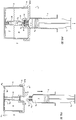
- the container assembly 10 generally includes a container 12 and a container closure 14.
- the container 12 includes an end wall 16 and a side wall 18.
- the end wall 16 and the side wall 18 may include any desirable material or geometry.
- the container 12 may include a clear plastic or glass material; in some implementations, the material may include a coating (e.g., an antimicrobial coating).
- the end wall 16 may define an annular member and the side wall 18 may define a cylindrical, tube-shaped body.
- the end wall 16 includes a central portion 16c and an outer perimeter portion 16 P .
- the side wall 18 includes a proximal end 18p and a distal end 18 D .
- the proximal end 18p of the side wall 18 is connected to and extends away from the outer perimeter portion 16 P of the end wall 16.
- the end wall 16 includes an inner surface 16 I and an outer surface 16o.
- the inner surface 16 I of the end wall 16 may be conically-pitched according to an angle, ⁇ , to define the central portion 16c of the end wall 16 the container 12 to be a low point of the inner surface 16 I of the end wall 16 of the container 12.
- the angle may be approximately equal to 15°.
- the container 12 may optionally include an adhesive 11 applied over the outer surface 16 O of the end wall 16.
- an optional release paper 13 may be applied over the adhesive 11.
- a user may remove the release paper (thereby exposing the adhesive 11 applied over the outer surface 16 O of the end wall 16); the exposed adhesive 13 may assist in the prevention of movement of the container 12 upon the support surface once the outer surface 16 O of the end wall 16 is arranged upon the support surface.
- the side wall 18 includes an inner surface 18 I and an outer surface 18o.
- a first portion 18 O-P1 of the outer surface 18 O of the side wall 18 may define an outer threaded surface 20 of the container 12.
- a second portion 18 O-P2 of the outer surface 18 O of the side wall 18 may include printed indicia 22 (as seen in FIG. 1 ) defining, for example, an amount of fluid disposed within the container 12.
- the outer threaded surface 20 of the container 12 may cooperate with an inner threaded surface 32 of the container closure 14 for selectively attaching the container closure 14 to the container 12.
- the container 12 forms a fluid reservoir 24 that is defined by the inner surface 16 I , 18 I of both of the end wall 16 and the side wall 18. Access to the fluid reservoir 24 is permitted by an opening 26 formed by the distal end 18 D of the side wall 18.
- the container closure 14 includes an end wall 28 and a side wall 30.
- the end wall 28 and the side wall 30 may include any desirable material or geometry.
- the container closure 14 may include an opaque plastic material; in some implementations, the material may include a coating (e.g., an antimicrobial coating).
- the end wall 28 may define an annular member and the side wall 30 may define a cylindrical, tube-shaped body.
- the end wall 28 includes a central portion 28c and an outer perimeter portion 28 P .
- the side wall 30 includes a proximal end 30 P and a distal end 30 D .
- the proximal end 30 P of the side wall 30 is connected to and extends away from the outer perimeter portion 28 P of the end wall 28.
- the central portion 28c of the end wall 28 of the container closure 14 and the central portion 16c of the end wall 16 of the container 12 may be aligned with a central axis, A-A, extending through the container assembly 10.
- the end wall 28 includes an inner surface 28 I and an outer surface 28 O .
- the side wall 30 includes an inner surface 30 I and an outer surface 30 O .
- the inner surface 30 I of the side wall 30 may define an inner threaded surface 32 of the container closure 14. As will be described in the following disclosure, the inner threaded surface 32 of the container closure 14 may cooperate with the outer threaded surface 20 of the container 12 for selectively attaching the container closure 14 to the container 12.
- the outer surface 28 O of the end wall 28 of the container closure 14 generally defines a syringe-engaging portion, such as, for example, a syringe-receiving bore 34.
- the syringe-receiving bore 34 is formed in the central portion 28c of the end wall 28 of the container closure 14. An axial center of the syringe-receiving bore 34 is aligned with the central axis, A-A.
- the syringe-receiving bore 34 is defined by portions 36, 38, 40 of the outer surface 28 O of the end wall 28 of the container closure 14 and sized for receiving a distal end, S D (see, e.g., FIGS. 2B-2E ), of a syringe, S (see, e.g., FIGS. 2B-2E ).
- the portions 36, 38, 40 of the outer surface 28 O of the end wall 28 of the container closure 14 includes: a first shoulder surface 36, a second shoulder surface 38 and an axial wall surface 40 extending substantially perpendicularly from the second shoulder surface 38 and connects the first shoulder surface 36 to the second shoulder surface 38.
- the first shoulder surface 36 may be tapered in order to conform to a tapered outer wall surface portion of the distal end, S D , of the syringe, S.
- the container closure 14 also includes a fluid-drawing member 42 that extends axially away from and is integral with the inner surface 28 I of the end wall 28 of the container closure 14.
- the fluid-drawing member 42 includes a proximal end 42 P and a distal end 42 D .
- a fluid-flow passage 44 extends through the fluid-drawing member 42 between the proximal end 42 P and the distal end 42 D .
- the fluid-flow passage 44 is aligned with an axial center of the fluid-drawing member 42.
- the proximal end 42 P of the fluid-drawing member 42 is connected to and extends away from the inner surface 28 I of the end wall 28 of the container closure 14.
- the fluid-drawing member 42 may extend away from the inner surface 28 I at the central portion 28c of the end wall 28 of the container closure 14 (such that the fluid-drawing member 42 is aligned with the central axis, A-A, when the container closure 14 is attached to the container 12).
- the fluid-drawing member 42 may also be defined by a length dimension, L 42 .
- a portion of the syringe-receiving bore 34 may extend into a portion of the length, L 42 , defining the fluid-drawing member 42.
- the length dimension L 42 of the fluid-drawing member 42 may be approximately equal to, but slightly greater than a length L 18 of the side wall 18 of the container 12; due to the conically-pitched angle, ⁇ , formed by the inner surface 16 I of the end wall 16, upon connecting the container closure 14 to the container 12, the distal end 42 D of the fluid-drawing member 42 may be arranged substantially adjacent to but in a slightly spaced-apart relationship with respect to the inner surface 16 I of the end wall 16 defined by the central portion 16c of the end wall 16 that is aligned with the central axis, A-A.
- the fluid drawing member 42 is selectively positioned relative to the container 12 in order to draw a remainder of fluid, F, contained within the fluid reservoir 24 when all of the fluid, F, contained within the container 12 is nearly depleted as seen in FIG.2E .
- the container assembly 10 also includes a disk-shaped member 46 that is disposed upon and supported by one or both of the second shoulder surface 38 and the axial wall surface 40 defining the syringe-receiving bore 34.
- the disk-shaped member 46 may be secured to one or more of the second shoulder surface 38 and the axial wall surface 40 in any desirable fashion (e.g., with an adhesive or a friction-fit connection).
- the disk-shaped member 46 may be formed from any desirable material including, for example, foam, rubber or the like.
- the disk-shaped member 46 selectively prevents fluid communication between the syringe-receiving bore 34 and the fluid-flow passage 44.
- the disk-shaped member 46 also inhibits contaminates from surrounding atmosphere, A, from entering the fluid-flow passage 44 and into the fluid reservoir 24.
- the disk-shaped member 46 may include a slit 48 that is aligned with an axial center of both of the container closure 14 and the disk-shaped member 46.
- the slit 48 permits selective fluid communication with the fluid-flow passage 44 and the fluid reservoir 24 from surrounding atmosphere, A. Access to (i.e., fluid communication) with the fluid-flow passage 44 from a device (e.g., the syringe, S) that is located in surrounding atmosphere, A, is permitted when a distal tip, S DT , of the syringe, S, axially penetrates the slit 48 as seen in FIG. 2D .
- FIGS. 2B-2E a method for utilizing the container assembly 10 is described.
- the container closure 14 is shown disengaged from the container 12, and, a fluid, F, is disposed within the fluid reservoir 24.
- the container closure 14 is connected (e.g., threadingly-connected) to the container 12 by, for example, the cooperating threaded surfaces 20, 32 of the container 12 and container closure 14 thereby fluidly sealing the fluid reservoir 24 from surrounding atmosphere, A.
- the distal end, S D , of the syringe, S may be axially-aligned with and arranged over the syringe-receiving bore 34 formed in the central portion 28c of the end wall 28 of the container closure 14.
- the distal end, S D , of the syringe, S is inserted into the syringe-receiving bore 34 and the distal tip, S DT , of the syringe, S, axially penetrates the slit 48 to thereby arrange a fluid reservoir, S R , of the syringe, S, in fluid communication with the fluid-flow passage 44 that is in fluid communication with the fluid, F, contained by the fluid reservoir 24.
- a user may axially manipulate a plunger, S P , of the syringe, S, in order to draw the fluid, F, from the fluid reservoir 24 into the fluid reservoir, S R , of the syringe, S, by way of the fluid-flow passage 44.
- the user may remove the distal end, S D , of the syringe, S, from the syringe-receiving bore 34.
- the conically-pitched angle, ⁇ formed by the inner surface 16 I of the end wall 16, directs a remainder of non-withdrawn fluid, F, disposed upon the inner surface 16 I of the end wall 16 (with the assistance of gravity) away from the outer perimeter portion 16 P of the end wall 16 and toward the central portion 16c of the end wall 16; as a result, the remainder of the non-withdrawn fluid, F, may be arranged / aligned with the fluid-flow passage 44 for subsequent withdrawal from the container 12.
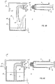
- the container assembly 10 1 generally includes a container 12 1 and a container closure 14 1 .
- the container 12 1 includes an end wall 16 1 and a side wall 18 1 .
- the end wall 16 1 and the side wall 18 1 may include any desirable material or geometry.
- the container 12 1 may include a clear plastic or glass material; in some implementations, the material may include a coating (e.g., an antimicrobial coating).
- the end wall 16 1 may define an annular member and the side wall 18 1 may define a cylindrical, tube-shaped body.
- the end wall 16 1 includes a central portion 16 C 1 and an outer perimeter portion 16 P 1 .
- the side wall 18 1 includes a proximal end 18 P 1 and a distal end 18 D 1 .
- the proximal end 18 P 1 of the side wall 18 1 is connected to and extends away from the outer perimeter portion 16 P 1 of the end wall 16 1 .
- the end wall 16 1 includes an inner surface 16 I 1 and an outer surface 16 O 1 .
- the inner surface 16 I 1 of the end wall 16 1 may be conically-pitched according to an angle, ⁇ , to define the central portion 16 C 1 of the end wall 16 C 1 the container 12 1 to be a low point of the inner surface 16 I 1 of the end wall 16 1 of the container 12 1 .
- the angle may be approximately equal to 15°.
- the container 12 1 may optionally include an adhesive 11 1 applied over the outer surface 16 O 1 of the end wall 16 1 .
- an optional release paper 13 1 may be applied over the adhesive 11 1 .
- a user may remove the release paper (thereby exposing the adhesive 11 1 applied over the outer surface 16 O 1 of the end wall 16 1 ); the exposed adhesive 13 1 may assist in the prevention of movement of the container 12 1 upon the support surface once the outer surface 16 O 1 of the end wall 16 1 is arranged upon the support surface.
- the side wall 18 1 includes an inner surface 18 I 1 and an outer surface 18 O 1 .
- a first portion 18 O-P1 1 of the outer surface 18 O 1 of the side wall 18 1 may define an outer threaded surface 20 1 of the container 12 1 .
- a second portion 18 O-P2 1 of the outer surface 18 O 1 of the side wall 18 1 may include printed indicia 22 1 (as seen in FIG. 3 ) defining, for example, an amount of fluid disposed within the container 12 1 .
- the outer threaded surface 20 1 of the container 12 1 may cooperate with an inner threaded surface 32 1 of the container closure 14 1 for selectively attaching the container closure 14 1 to the container 12 1 .
- the container 12 1 forms a fluid reservoir 24 1 that is defined by the inner surface 16 I 1 , 18 I 1 of both of the end wall 16 1 and the side wall 18 1 . Access to the fluid reservoir 24 1 is permitted by an opening 26 1 formed by the distal end 18 D 1 of the side wall 18 1 .
- the container closure 14 1 includes an end wall 28 1 and a side wall 30 1 .
- the end wall 28 1 and the side wall 30 1 may include any desirable material or geometry.
- the container closure 14 1 may include an opaque plastic material; in some implementations, the material may include a coating (e.g., an antimicrobial coating).
- the end wall 28 1 may define an annular member and the side wall 30 1 may define a cylindrical, tube-shaped body.
- the end wall 28 1 includes a central portion 28 C 1 and an outer perimeter portion 28 P 1 .
- the side wall 30 1 includes a proximal end 30 P 1 and a distal end 30 D 1 .
- the proximal end 30 P 1 of the side wall 30 1 is connected to and extends away from the outer perimeter portion 28 P 1 of the end wall 28 1 .
- the central portion 28 C 1 of the end wall 28 1 of the container closure 14 1 and the central portion 16 C 1 of the end wall 16 1 of the container 12 1 may be aligned with a central axis, A-A, extending through the container assembly 10 1 .
- the end wall 28 1 includes an inner surface 28 I 1 and an outer surface 28 O 1 .
- the side wall 30 1 includes an inner surface 30 I 1 and an outer surface 30 O 1 .
- a portion of the inner surface 30 I 1 of the side wall 30 1 may define an inner threaded surface 32 1 of the container closure 14 1 .
- the inner threaded surface 32 1 of the container closure 14 1 may cooperate with the outer threaded surface 20 1 of the container 12 1 for selectively attaching the container closure 14 1 to the container 12 1 .
- a portion of the outer surface 30 O 1 of the side wall 30 1 of the container closure 14 1 generally defines a syringe-engaging portion, such as, for example, a syringe-receiving bore 34 1 .
- the syringe-receiving bore 34 1 is not axially-aligned with the central axis, A-A; rather, an axial center of the syringe-receiving bore 34 1 is arranged substantially perpendicularly with respect to the central axis, A-A. Because the syringe-receiving bore 34 1 is arranged in a radial orientation (as opposed to an axial orientation described above at FIGS.
- contaminates that may fall with gravity are less likely to infiltrate the syringe-receiving bore 34 1 .
- the syringe-engaging portion is shown as a syringe-receiving bore 34 1 that is arranged substantially perpendicularly with respect to the central axis, A-A at FIGS. 3-4E
- the syringe-engaging portion 34 1 at FIGS. 3-4E is not limited to a bore and may include other structure configurations such as, for example, a Luer lock (see, e.g., 34 2 , 34 3 in FIGS.
- the syringe-receiving bore 34 1 is defined by portions 36 1 , 38 1 , 40 1 of the outer surface 30 O 1 of the side wall 30 1 of the container closure 14 1 and sized for receiving a distal end, S D , of a syringe, S.
- the portions 36 1 , 38 1 , 40 1 of the outer surface 30 O 1 of the side wall 30 1 of the container closure 14 1 includes: a first shoulder surface 36 1 , a second shoulder surface 38 1 and an axial wall surface 40 1 extending substantially perpendicularly from the second shoulder surface 38 1 and connects the first shoulder surface 36 1 to the second shoulder surface 38 1 .
- the first shoulder surface 36 1 may be tapered in order to conform to a tapered outer wall surface portion of the distal end, S D , of the syringe, S.
- the container closure 14 1 also includes a fluid-drawing member 42 1 having a radial segment 42 S1 1 and an axial segment 42 S2 1 .
- the radial segment 42 S1 1 is integral with and extends in a radial direction (with respect to the central axis, A-A) away from the inner surface 30 I 1 of the side wall 30 1 of the container closure 14 1 .
- the fluid-drawing member 42 1 deviates from a radially-extending direction (defined by the radial segment 42 S1 1 ) to an axially-extending direction (defined by the axial segment 42 S2 1 , which is aligned with the central axis, A-A).
- the fluid-drawing member 42 1 includes a proximal end 42 P 1 and a distal end 42 D 1 .
- a fluid-flow passage 44 1 extends through the fluid-drawing member 42 1 between the proximal end 42 P 1 and the distal end 42 D 1 .
- the fluid-flow passage 44 1 includes a radial segment 44 S1 1 and an axial segment 44 S2 1 .
- the fluid-flow passage 44 1 is in fluid communication with the fluid reservoir 24 1 defined by the container 12 1 .
- the proximal end 42 P 1 of the fluid-drawing member 42 1 is connected to and extends away from the inner surface 30 I 1 of the side wall 30 1 of the container closure 14 1 .
- the fluid-drawing member 42 1 may also be defined by a length dimension, L 42 1 , that is referenced from the inner surface 28 I 1 of the 28 1 .
- the length dimension, L 42 1 extends between the inner surface 28 I 1 of the 28 1 and the distal end 42 D 1 of the fluid-drawing member 42 1 .
- the syringe-receiving bore 34 1 may extend into a portion of the fluid-drawing member 42 1 at the proximal end 42 P 1 of the fluid-drawing member 42 1 .
- the length dimension L 42 1 of the fluid-drawing member 42 1 may be approximately equal to, but slightly greater than a length L 18 1 of the side wall 18 1 of the container 12 1 ; due to the conically-pitched angle, ⁇ , formed by the inner surface 16 I 1 of the end wall 16 1 , upon connecting the container closure 14 1 to the container 12 1 , the distal end 42 D 1 of the fluid-drawing member 42 1 may be arranged substantially adjacent to but in a slightly spaced-apart relationship with respect to the inner surface 16 I 1 of the end wall 16 1 defined by the central portion 16 C 1 of the end wall 16 1 that is aligned with the central axis, A-A.
- the fluid drawing member 42 1 is selectively positioned relative to the container 12 1 in order to draw a remainder of fluid, F, contained within the fluid reservoir 24 1 when all of the fluid, F, contained within the container 12 1 is nearly depleted (as seen, e.g., in FIG. 4E ).
- the container assembly 10 1 also includes a disk-shaped member 46 1 that is disposed upon and supported by one or both of the second shoulder surface 38 1 and the axial wall surface 40 1 defining the syringe-receiving bore 34 1 .
- the disk-shaped member 46 1 may be secured to one or more of the second shoulder surface 38 1 and the axial wall surface 40 1 in any desirable fashion (e.g., with an adhesive or a friction-fit connection).
- the disk-shaped member 46 1 may be formed from any desirable material including, for example, foam, rubber or the like.
- the disk-shaped member 46 1 selectively prevents fluid communication between the syringe-receiving bore 34 1 and the fluid-flow passage 44 1 .
- the disk-shaped member 46 1 also inhibits contaminates from surrounding atmosphere, A, from entering the fluid-flow passage 44 1 and into the fluid reservoir 24 1 .
- the disk-shaped member 46 1 may include a slit 48 1 that is aligned with an axial center of the disk-shaped member 46 1 .
- the slit 48 1 permits selective fluid communication with the fluid-flow passage 44 1 and the fluid reservoir 24 1 from surrounding atmosphere, A. Access to (i.e., fluid communication) with the fluid-flow passage 44 1 from a device (e.g., the syringe, S) that is located in surrounding atmosphere, A, is permitted when a distal tip, S DT , of the syringe, S, axially penetrates the slit 48 1 (as seen, e.g., in FIG. 4D ).
- the container closure 14 1 may be arranged in a disengaged state with respect to the container 12 1 , and, a fluid, F, is disposed within the fluid reservoir 24 1 .
- the container closure 14 1 may be threadingly-connected to the container 12 1 by the cooperating threaded surfaces 20 1 , 32 1 of the container 12 1 and container closure 14 1 thereby fluidly sealing the fluid reservoir 24 1 from surrounding atmosphere, A.
- the distal end, S D , of the syringe, S may be aligned with and arranged over the syringe-receiving bore 34 1 formed in the side wall 30 1 of the container closure 14 1 .
- the distal end, S D , of the syringe, S is inserted into the syringe-receiving bore 34 1 and the distal tip, S DT , of the syringe, S, axially penetrates the slit 48 1 to thereby arrange a fluid reservoir, S R , of the syringe, S, in fluid communication with the fluid-flow passage 44 1 that is in fluid communication with the fluid, F, contained by the fluid reservoir 24 1 .
- a user may axially manipulate a plunger, S P , of the syringe, S, in order to draw the fluid, F, from the fluid reservoir 24 1 into the fluid reservoir, S R , of the syringe, S, by way of the fluid-flow passage 44 1 .
- the user may remove the syringe, S, from the syringe-receiving bore 34 1 .
- the conically-pitched angle, ⁇ formed by the inner surface 16 I 1 of the end wall 16 1 , directs a remainder of non-withdrawn fluid, F, disposed upon the inner surface 16 I 1 of the end wall 16 1 (with the assistance of gravity) away from the outer perimeter portion 16 P 1 of the end wall 16 1 and toward the central portion 16 C 1 of the end wall 16 1 ; as a result, the remainder of the non-withdrawn fluid, F, may be arranged / aligned with the fluid-flow passage 44 1 for subsequent withdrawal from the container 12 1 .
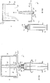
- the container assembly 10 2 generally includes a container 12 2 and a container closure 14 2 .
- the container 12 2 includes an end wall 16 2 and a side wall 18 2 .
- the end wall 16 2 and the side wall 18 2 may include any desirable material or geometry.
- the container 12 2 may include a clear plastic or glass material; in some implementations, the material may include a coating (e.g., an antimicrobial coating).
- the end wall 16 2 may define an annular member and the side wall 18 2 may define a cylindrical, tube-shaped body.
- the end wall 16 2 includes a central portion 16 C 2 and an outer perimeter portion 16 P 2 .
- the side wall 18 2 includes a proximal end 18 P 2 and a distal end 18 D 2 .
- the proximal end 18 P 2 of the side wall 18 2 is connected to and extends away from the outer perimeter portion 16 P 2 of the end wall 16 2 .
- the end wall 16 2 includes an inner surface 16 I 2 and an outer surface 16 O 2 .
- the inner surface 16 I 2 of the end wall 16 2 may be conically-pitched according to an angle, ⁇ , to define the central portion 16 C 2 of the end wall 16 2 the container 12 2 to be a low point of the inner surface 16 I 2 of the end wall 16 2 of the container 12 2 .
- the angle may be approximately equal to 15°.
- the container 12 2 may optionally include an adhesive 11 2 applied over the outer surface 16 O 2 of the end wall 16 2 .
- an optional release paper 13 2 may be applied over the adhesive 11 2 .
- a user may remove the release paper (thereby exposing the adhesive 11 2 applied over the outer surface 16 O 2 of the end wall 16 2 ); the exposed adhesive 13 2 may assist in the prevention of movement of the container 12 2 upon the support surface once the outer surface 16 O 2 of the end wall 16 2 is arranged upon the support surface.
- the side wall 18 2 includes an inner surface 18 I 2 and an outer surface 18 O 2 .
- a first portion 18 O-P1 2 of the outer surface 18 O 2 of the side wall 18 2 may define an outer threaded surface 20 2 of the container 12 2 .
- a second portion 18 O-P2 2 of the outer surface 18 O 2 of the side wall 18 2 may include printed indicia 22 2 (as seen in FIG. 5 ) defining, for example, an amount of fluid disposed within the container 12 2 .
- the outer threaded surface 20 2 of the container 12 2 may cooperate with an inner threaded surface 32 2 of the container closure 14 2 for selectively attaching the container closure 14 2 to the container 12 2 .
- the container 12 2 forms a fluid reservoir 24 2 that is defined by the inner surface 16 I 2 , 18 I 2 of both of the end wall 16 2 and the side wall 18 2 . Access to the fluid reservoir 24 2 is permitted by an opening 26 2 formed by the distal end 18 D 2 of the side wall 18 2 .
- the container closure 14 2 includes an end wall 28 2 and a side wall 30 2 .
- the end wall 28 2 and the side wall 30 2 may include any desirable material or geometry.
- the container closure 14 2 may include an opaque plastic material; in some implementations, the material may include a coating (e.g., an antimicrobial coating).
- the end wall 28 2 may define an annular member and the side wall 30 2 may define a cylindrical, tube-shaped body.
- the end wall 28 2 includes a central portion 28 C 2 and an outer perimeter portion 28 P 2 .
- the side wall 30 2 includes a proximal end 30 P 2 and a distal end 30 D 2 .
- the proximal end 30 P 2 of the side wall 30 2 is connected to and extends away from the outer perimeter portion 28 P 2 of the end wall 28 2 .
- the central portion 28 C 2 of the end wall 28 2 of the container closure 14 2 and the central portion 16 C 2 of the end wall 16 2 of the container 12 2 may be aligned with a central axis, A-A, extending through the container assembly 10 2 .
- the end wall 28 2 includes an inner surface 28 I 2 and an outer surface 28 O 2 .
- the side wall 30 2 includes an inner surface 30 I 2 and an outer surface 30 O 2 .
- the inner surface 30 I 2 of the side wall 30 2 may define an inner threaded surface 32 2 of the container closure 14 2 .
- the inner threaded surface 32 2 of the container closure 14 2 may cooperate with the outer threaded surface 20 2 of the container 12 2 for selectively attaching the container closure 14 2 to the container 12 2 .
- the container closure 14 2 may further include a syringe-engaging portion 34 2 formed by and extending axially-away from the outer surface 28 O 2 of the end wall 28 2 of the container closure 14 2 .
- the syringe-engaging portion 34 2 is axially aligned with the central portion 28 C 2 of the end wall 28 2 of the container closure 14 2 .
- An axial center of the syringe-engaging portion 34 2 is aligned with the central axis, A-A.
- the syringe-engaging portion 34 2 is generally defined by a substantially cylindrical tube-shaped member having an outer threaded surface 34 T 2 .
- the outer threaded surface 34 T 2 of the syringe-engaging portion 34 2 engages an inner threaded surface portion, S T (as seen in, e.g., FIG. 6B ), of the syringe, S, which may be referred to as a Luer lock.
- the substantially cylindrical tube-shaped member defining the syringe-engaging portion 34 2 is sized for being correspondingly inserted into a distal end, S D , of a syringe, S, which is defined by an outer tube-shaped member (having the inner threaded surface, S T ) and an inner tube-shaped member.
- the inner tube-shaped member defines a distal tip, S DT , of the syringe, S, that is inserted into a passage 34 P 2 formed by the cylindrical tube-shaped member of the syringe-engaging portion 34 2 .
- a distal end of the syringe-engaging portion 34 2 may be defined by portions 36 2 , 38 2 , 40 2 of the outer surface 28 O 2 of the end wall 28 2 of the container closure 14 2 , and includes, for example: a first shoulder surface 36 2 , a second shoulder surface 38 2 and an axial wall surface 40 2 extending substantially perpendicularly from the second shoulder surface 38 2 and connects the first shoulder surface 36 2 to the second shoulder surface 38 2 .
- the container closure 14 2 also includes a fluid-drawing member 42 2 that extends axially away from and is integral with the inner surface 28 I 2 of the end wall 28 2 of the container closure 14 2 .
- the fluid-drawing member 42 2 includes a proximal end 42 P 2 and a distal end 42 D 2 .
- a fluid-flow passage 44 2 extends through the fluid-drawing member 42 2 between the proximal end 42 P 2 and the distal end 42 D 2 .
- the fluid-flow passage 44 2 also axially extends into the syringe-engaging portion 34 2 .
- the fluid-flow passage 44 2 is aligned with an axial center of the fluid-drawing member 42 2 .
- the proximal end 42 P 2 of the fluid-drawing member 42 2 is connected to and extends away from the inner surface 28 I 2 of the end wall 28 2 of the container closure 14 2 .
- the fluid-drawing member 42 2 may extend away from the inner surface 28 I 2 at the central portion 28 C 2 of the end wall 28 2 of the container closure 14 2 (such that the fluid-drawing member 42 2 is aligned with the central axis, A-A, when the container closure 14 2 is attached to the container 12 2 ).
- the fluid-drawing member 42 2 may also be defined by a length dimension, L 42 2 .
- the length dimension L 42 2 of the fluid-drawing member 42 2 may be approximately equal to, but slightly greater than a length L 18 2 of the side wall 18 2 of the container 12 2 ; due to the conically-pitched angle, ⁇ , formed by the inner surface 16 I 2 of the end wall 16 2 , upon connecting the container closure 14 2 to the container 12 2 , the distal end 42 D 2 of the fluid-drawing member 42 2 may be arranged substantially adjacent to but in a slightly spaced-apart relationship with respect to the inner surface 16 I 2 of the end wall 16 2 defined by the central portion 16 C 2 of the end wall 16 2 that is aligned with the central axis, A-A.
- the fluid drawing member 42 2 is selectively positioned relative to the container 12 2 in order to draw a remainder of fluid, F, contained within the fluid reservoir 24 2 when all of the fluid, F, contained within the container 12 2 is nearly depleted as seen in FIG. 6E .
- the container assembly 10 2 also includes a disk-shaped member 46 2 that is disposed upon and supported by one or both of the second shoulder surface 38 2 and the axial wall surface 40 2 defined by the distal end of the syringe-engaging portion 34 2 .
- the disk-shaped member 46 2 may be secured to one or more of the second shoulder surface 38 2 and the axial wall surface 40 2 in any desirable fashion (e.g., with an adhesive or a friction-fit connection).
- the disk-shaped member 46 2 may be formed from any desirable material including, for example, foam, rubber or the like.
- the disk-shaped member 46 2 inhibits contaminates from surrounding atmosphere, A, from entering the fluid-flow passage 44 2 and into the fluid reservoir 24 2 .
- the disk-shaped member 46 2 may include a slit 48 2 that is aligned with an axial center of both of the container closure 14 2 and the disk-shaped member 46 2 .
- the slit 48 2 selectively permits selective fluid communication with the fluid-flow passage 44 2 and the fluid reservoir 24 2 from surrounding atmosphere, A. Access to (i.e., fluid communication) with the fluid-flow passage 44 2 from a device (e.g., the syringe, S) that is located in surrounding atmosphere, A, is permitted when a distal tip, S DT , of the syringe, S, axially penetrates the slit 48 2 , as seen in FIG. 6D
- FIGS. 6B-6E a method for utilizing the container assembly 10 2 is described.
- the container closure 14 2 is shown disengaged from the container 12 2 , and, a fluid, F, is disposed within the fluid reservoir 24 2 .
- the container closure 14 2 is connected (e.g., threadingly-connected) to the container 12 2 by, for example, the cooperating threaded surfaces 20 2 , 32 2 of the container 12 2 and container closure 14 2 thereby fluidly sealing the fluid reservoir 24 2 from surrounding atmosphere, A.
- the distal end, S D , of the syringe, S may be aligned with and arranged over the syringe-engaging portion 34 2 extending axially away from the central portion 28 C 2 of the end wall 28 2 of the container closure 14 2 .
- the syringe, S may be connected to the syringe-engaging portion 34 2 by axially rotating, R, the syringe, S, relative to the syringe-engaging portion 34 2 such that the inner threaded surface portion, S T , of the syringe, S, threadingly-engages the outer threaded surface 34 T 2 of the syringe-engaging portion 34 2 .
- a user may axially manipulate a plunger, S P , of the syringe, S, in order to draw the fluid, F, from the fluid reservoir 24 2 into the fluid reservoir, S R , of the syringe, S, by way of the fluid-flow passage 44 2 .
- the user may axially rotate, R', the syringe, S, in a direction opposite that of the rotational direction, R, in order to axially disconnect the distal end, S D , of the syringe, S, from the syringe-engaging portion 34 2 .
- the conically-pitched angle, ⁇ formed by the inner surface 16 I 2 of the end wall 16 2 , directs a remainder of non-withdrawn fluid, F, disposed upon the inner surface 16 I 2 of the end wall 16 2 (with the assistance of gravity) away from the outer perimeter portion 16 P 2 of the end wall 16 2 and toward the central portion 16 C 2 of the end wall 16 2 ; as a result, the remainder of the non-withdrawn fluid, F, may be arranged / aligned with the fluid-flow passage 44 2 for subsequent withdrawal from the container 12 2 .
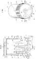
- the container assembly 103 generally includes a container 12 3 and a container closure 14 3 .
- the container 12 3 includes an end wall 16 3 and a side wall 18 3 .
- the end wall 16 3 and the side wall 18 3 may include any desirable material or geometry.
- the container 12 3 may include a clear plastic or glass material; in some implementations, the material may include a coating (e.g., an antimicrobial coating).
- the end wall 16 3 may define an annular member and the side wall 18 3 may define a cylindrical, tube-shaped body.
- the end wall 16 3 includes a central portion 16 C 3 and an outer perimeter portion 16 P 3 .
- the side wall 18 3 includes a proximal end 18 P 3 and a distal end 18 D 3 .
- the proximal end 18 P 3 of the side wall 18 3 is connected to and extends away from the outer perimeter portion 16 P 3 of the end wall 16 3 .
- the end wall 16 3 includes an inner surface 16 I 3 and an outer surface 16 O 3 .
- the inner surface 16 I 3 of the end wall 16 3 may be conically-pitched according to an angle, ⁇ , to define the central portion 16 C 3 of the end wall 16 3 the container 12 3 to be a low point of the inner surface 16 I 3 of the end wall 16 3 of the container 12 3 .
- the angle may be approximately equal to 15°.
- the container 12 3 may optionally include an adhesive 11 3 applied over the outer surface 16 O 3 of the end wall 16 3 .
- an optional release paper 13 3 may be applied over the adhesive 11 3 .
- a user may remove the release paper (thereby exposing the adhesive 11 3 applied over the outer surface 16 O 3 of the end wall 16 3 ); the exposed adhesive 13 3 may assist in the prevention of movement of the container 12 3 upon the support surface once the outer surface 16 O 3 of the end wall 16 3 is arranged upon the support surface.
- the side wall 18 3 includes an inner surface 18 I 3 and an outer surface 18 O 3 .
- a first portion 18 O-P1 3 of the outer surface 18 O 3 of the side wall 18 3 may define an outer threaded surface 20 3 of the container 12 3 .
- a second portion 18 O-P2 3 of the outer surface 18 O 3 of the side wall 18 3 may include printed indicia 22 3 (as seen in FIG. 7 ) defining, for example, an amount of fluid disposed within the container 12 3 .
- the outer threaded surface 203 of the container 12 3 may cooperate with an inner threaded surface 32 3 of the container closure 14 3 for selectively attaching the container closure 14 3 to the container 12 3 .
- the container 12 3 forms a fluid reservoir 24 3 that is defined by the inner surface 16 I 3 , 18 I 3 of both of the end wall 16 3 and the side wall 18 3 . Access to the fluid reservoir 24 3 is permitted by an opening 26 3 formed by the distal end 18 D 3 of the side wall 18 3 .
- the container closure 14 3 includes an end wall 28 3 and a side wall 30 3 .
- the end wall 28 3 and the side wall 30 3 may include any desirable material or geometry.
- the container closure 14 3 may include an opaque plastic material; in some implementations, the material may include a coating (e.g., an antimicrobial coating).
- the end wall 28 3 may define an annular member and the side wall 30 3 may define a cylindrical, tube-shaped body.
- the end wall 28 3 includes a central portion 28 C 3 and an outer perimeter portion 28 P 3 .
- the side wall 30 3 includes a proximal end 30 P 3 and a distal end 30 D 3 .
- the proximal end 30 P 3 of the side wall 30 3 is connected to and extends away from the outer perimeter portion 28 P 3 of the end wall 28 3 .
- the central portion 28 C 3 of the end wall 28 3 of the container closure 14 3 and the central portion 16 C 3 of the end wall 16 3 of the container 12 3 may be aligned with a central axis, A-A, extending through the container assembly 103.
- the end wall 28 3 includes an inner surface 28 I 3 and an outer surface 28 O 3 .
- the side wall 30 3 includes an inner surface 30 I 3 and an outer surface 30 O 3 .
- the inner surface 30 I 3 of the side wall 30 3 may define an inner threaded surface 32 3 of the container closure 14 3 .
- the inner threaded surface 32 3 of the container closure 14 3 may cooperate with the outer threaded surface 203 of the container 12 3 for selectively attaching the container closure 14 3 to the container 12 3 .
- the container closure 14 3 may further include a syringe-engaging portion 34 3 formed by the outer surface 28 O 3 of the end wall 28 3 of the container closure 14 3 .
- the syringe-engaging portion 34 3 is substantially similar to the syringe-engaging portion 34 2 described above at FIGS. 5-6E with the exception that the syringe-engaging portion 34 3 is recessed within a bore 35 3 formed in the outer surface 28 O 3 of the end wall 28 3 of the container closure 14 3 (rather than extending axially away from the outer surface 28 O 2 of the end wall 28 2 of the container closure 14 2 as seen above at FIGS. 5-6E ).
- the syringe-engaging portion 34 3 By arranging the syringe-engaging portion 34 3 in a recessed orientation within the bore 35 3 , the syringe-engaging portion 34 3 is protected from being unintentionally sheared off of the outer surface 28 O 3 of the end wall 28 3 of the container closure 14 3 .
- the syringe-engaging portion 34 3 is axially-aligned with the central portion 28 C 3 of the end wall 28 3 of the container closure 14 3 .
- An axial center of the syringe-engaging portion 34 3 is aligned with the central axis, A-A.
- the syringe-engaging portion 34 3 is generally defined by a substantially cylindrical tube-shaped member having an outer threaded surface 34 T 3 .
- the outer threaded surface 34 T 3 of the syringe-engaging portion 34 3 engages an inner threaded surface portion, S T (see, e.g., FIG. 8B ), of the syringe, S, which may be referred to as a Luer lock.
- the substantially cylindrical tube-shaped member defining the syringe-engaging portion 34 3 is sized for being correspondingly inserted into a distal end, S D , of a syringe, S, which is defined by an outer tube-shaped member (having the inner threaded surface, S T ) and an inner tube-shaped member.
- the inner tube-shaped member defines a distal tip, S DT , of the syringe, S, that is inserted into a passage 34 P 3 formed by the cylindrical tube-shaped member of the syringe-engaging portion 34 3 .
- a distal end of the syringe-engaging portion 34 3 may be defined by portions 36 3 , 38 3 , 40 3 of the outer surface 28 O 3 of the end wall 28 3 of the container closure 14 3 , and includes, for example: a first shoulder surface 36 3 , a second shoulder surface 38 3 and an axial wall surface 40 3 extending substantially perpendicularly from the second shoulder surface 38 3 and connects the first shoulder surface 36 3 to the second shoulder surface 38 3 .
- the container closure 14 3 also includes a fluid-drawing member 42 3 that extends axially away from and is integral with the inner surface 28 I 3 of the end wall 28 3 of the container closure 14 3 .
- the fluid-drawing member 42 3 includes a proximal end 42 P 3 and a distal end 42 D 3 .
- a fluid-flow passage 44 3 extends through the fluid-drawing member 42 3 between the proximal end 42 P 3 and the distal end 42 D 3 .
- the fluid-flow passage 44 3 also axially extends into the syringe-engaging portion 34 3 .
- the fluid-flow passage 44 3 is aligned with an axial center of the fluid-drawing member 42 3 .
- the proximal end 42 P 3 of the fluid-drawing member 42 3 is connected to and extends away from the inner surface 28 I 3 of the end wall 28 3 of the container closure 14 3 .
- the fluid-drawing member 42 3 may extend away from the inner surface 28 I 3 at the central portion 28 C 3 of the end wall 28 3 of the container closure 14 3 (such that the fluid-drawing member 42 3 is aligned with the central axis, A-A, when the container closure 14 3 is attached to the container 12 3 ).
- the fluid-drawing member 42 3 may also be defined by a length dimension, L 42 3 .
- the length dimension L 42 3 of the fluid-drawing member 42 3 may be approximately equal to, but slightly greater than a length L 18 3 of the side wall 18 3 of the container 12 3 ; due to the conically-pitched angle, ⁇ , formed by the inner surface 16 I 3 of the end wall 16 3 , upon connecting the container closure 14 3 to the container 12 3 , the distal end 42 D 3 of the fluid-drawing member 42 3 may be arranged substantially adjacent to but in a slightly spaced-apart relationship with respect to the inner surface 16 I 3 of the end wall 16 3 defined by the central portion 16 C 3 of the end wall 16 3 that is aligned with the central axis, A-A.
- the fluid drawing member 42 3 is selectively positioned relative to the container 12 3 in order to draw a remainder of fluid, F, contained within the fluid reservoir 24 3 when all of the fluid, F, contained within the container 12 3 is nearly depleted as seen in FIG. 8E .
- the container assembly 10 3 also includes a disk-shaped member 46 3 that is disposed upon and supported by one or both of the second shoulder surface 38 3 and the axial wall surface 40 3 defined by the distal end of the syringe-engaging portion 34 3 .
- the disk-shaped member 46 3 may be secured to one or more of the second shoulder surface 38 3 and the axial wall surface 40 3 in any desirable fashion (e.g., with an adhesive or a friction-fit connection).
- the disk-shaped member 46 3 may be formed from any desirable material including, for example, foam, rubber or the like.
- the disk-shaped member 46 3 inhibits contaminates from surrounding atmosphere, A, from entering the fluid-flow passage 44 3 and into the fluid reservoir 24 3 .
- the disk-shaped member 46 3 may include a slit 48 3 that is aligned with an axial center of both of the container closure 14 3 and the disk-shaped member 46 3 .
- the slit 48 3 selectively permits fluid communication between surrounding atmosphere, A, and the fluid-flow passage 44 3 that is fluidly-connected to the fluid reservoir 24 3 .
- Access to (i.e., fluid communication) with the fluid-flow passage 44 3 from a device (e.g., the syringe, S) that is located in surrounding atmosphere, A, is permitted when a distal tip, S DT , of the syringe, S, axially penetrates the slit 48 3 as seen in FIG. 8D .
- FIGS. 8B-8E a method for utilizing the container assembly 10 3 is described.
- the container closure 14 3 is shown disengaged from the container 12 3 , and, a fluid, F, is disposed within the fluid reservoir 24 3 .
- the container closure 14 3 is connected (e.g., threadingly-connected) to the container 12 3 by, for example, the cooperating threaded surfaces 20 3 , 32 3 of the container 12 3 and container closure 14 3 thereby fluidly sealing the fluid reservoir 24 3 from surrounding atmosphere, A.
- the distal end, S D , of the syringe, S may be aligned with and arranged over the syringe-engaging portion 34 3 extending axially away from the central portion 28 C 3 of the end wall 28 3 of the container closure 14 3 .
- the syringe, S may be connected to the syringe-engaging portion 34 3 by axially rotating, R, the syringe, S, relative to the syringe-engaging portion 34 3 such that the inner threaded surface portion, S T , of the syringe, S, threadingly-engages the outer threaded surface 34 T 3 of the syringe-engaging portion 34 3 .
- the distal end, S D , of the syringe, S is threadingly-connected to the syringe-engaging portion 34 3 such that the distal tip, S DT , of the syringe, S, axially penetrates the slit 48 3 to thereby arrange a fluid reservoir, S R , of the syringe, S, in fluid communication with the fluid-flow passage 44 3 that is in fluid communication with the fluid, F, contained by the fluid reservoir 24 3 .
- a user may axially manipulate a plunger, S P , of the syringe, S, in order to draw the fluid, F, from the fluid reservoir 24 3 into the fluid reservoir, S R , of the syringe, S, by way of the fluid-flow passage 44 3 .
- the user may axially rotate, R', the syringe, S, in a direction opposite that of the rotational direction, R, in order to axially disconnect the distal end, S D , of the syringe, S, from the syringe-engaging portion 34 3 .
- the conically-pitched angle, ⁇ formed by the inner surface 16 I 3 of the end wall 16 3 , directs a remainder of non-withdrawn fluid, F, disposed upon the inner surface 16 I 3 of the end wall 16 3 (with the assistance of gravity) away from the outer perimeter portion 16 P 3 of the end wall 16 3 and toward the central portion 16 C 3 of the end wall 16 3 ; as a result, the remainder of the non-withdrawn fluid, F, may be arranged / aligned with the fluid-flow passage 44 3 for subsequent withdrawal from the container 12 3 .
- the container assembly 10 4 generally includes a container 12 4 and a container closure 14 4 .
- the container 12 4 includes an end wall 16 4 and a side wall 18 4 .
- the end wall 16 4 and the side wall 18 4 may include any desirable material or geometry.
- the container 12 4 may include a clear plastic or glass material; in some implementations, the material may include a coating (e.g., an antimicrobial coating).
- the end wall 16 4 may define a square- or recetangular-shaped member and the side wall 18 4 may define four substantially flat panel portions; collectively, the end wall 16 4 and the side wall 18 4 define a cube-shaped body.
- the end wall 16 4 includes a central portion 16 C 4 and an outer perimeter portion 16 P 4 .
- the side wall 18 4 includes a proximal end 18 P 4 and a distal end 18 D 4 .
- the proximal end 18 P 4 of the side wall 18 4 is connected to and extends away from the outer perimeter portion 16 P 4 of the end wall 16 4 .
- the end wall 16 4 includes an inner surface 16 I 4 and an outer surface 16 O 4 .
- the inner surface 16 I 4 of the end wall 16 4 may be conically-pitched according to an angle, ⁇ , to define the central portion 16 C 4 of the end wall 16 4 the container 12 4 to be a low point of the inner surface 16 I 4 of the end wall 16 4 of the container 12 4 .
- the angle may be approximately equal to 15°.
- the container 12 4 may optionally include an adhesive 11 4 applied over the outer surface 16 O 4 of the end wall 16 4 .
- an optional release paper 13 4 may be applied over the adhesive 11 4 .
- a user may remove the release paper (thereby exposing the adhesive 11 4 applied over the outer surface 16 O 4 of the end wall 16 4 ); the exposed adhesive 13 4 may assist in the prevention of movement of the container 12 4 upon the support surface once the outer surface 16 O 4 of the end wall 16 4 is arranged upon the support surface.
- the side wall 18 4 includes an inner surface 18 I 4 and an outer surface 18 O 4 .
- a first portion 18 O-P1 4 of the outer surface 18 O 4 of the side wall 18 4 may define a first portion of a snap-fit connection (such as, for example, a projection 20 4 of the container 12 4 ).
- a second portion 18 O-P2 4 of the outer surface 18 O 4 of the side wall 18 4 may include printed indicia 22 4 (as seen in FIG. 9 ) defining, for example, an amount of fluid disposed within the container 12 4 .
- the portion of the snap-fit connection 20 4 of the container 12 4 may cooperate with a second portion of a snap-fit connection (such as, e.g., a recess 32 4 ) of the container closure 14 4 for selectively attaching the container closure 14 4 to the container 12 4 .
- a second portion of a snap-fit connection such as, e.g., a recess 32 4
- the container 12 4 forms a fluid reservoir 24 4 that is defined by the inner surface 16 I 4 , 18 I 4 of both of the end wall 16 4 and the side wall 18 4 . Access to the fluid reservoir 24 4 is permitted by an opening 26 4 formed by the distal end 18 D 4 of the side wall 18 4 .
- the container closure 14 4 includes an end wall 28 4 and a side wall 30 4 .
- the end wall 28 4 and the side wall 30 4 may include any desirable material or geometry.
- the container closure 14 4 may include an opaque plastic material; in some implementations, the material may include a coating (e.g., an antimicrobial coating).
- the end wall 28 4 may define a square- or rectangular-shaped member and the side wall 30 4 may define four substantially flat panel portions; collectively, the end wall 28 4 and the side wall 30 4 define a cube-shaped body.
- the end wall 28 4 includes a central portion 28 C 4 and an outer perimeter portion 28 P 4 .
- the side wall 30 4 includes a proximal end 30 P 4 and a distal end 30 D 4 .
- the proximal end 30 P 4 of the side wall 30 P 4 is connected to and extends away from the outer perimeter portion 28 P 4 of the end wall 28 4 .
- the central portion 28 C 4 of the end wall 28 C 4 of the container closure 14 4 and the central portion 16 C 4 of the end wall 16 4 of the container 12 4 may be aligned with a central axis, A-A, extending through the container assembly 10 4 .
- the end wall 28 4 includes an inner surface 28 I 4 and an outer surface 28 O 4 .
- the side wall 30 4 includes an inner surface 30 I 4 and an outer surface 30 O 4 .
- the inner surface 30 I 4 of the side wall 30 4 may define the second portion of a snap-fit connection (such as, e.g., a recess 32 4 ) of the container closure 14 4 .
- the recess 32 4 of the container closure 14 4 may cooperate with the projection 20 4 of the container 12 4 for selectively attaching the container closure 14 4 to the container 12 4 .
- the outer surface 28 O 4 of the end wall 28 4 of the container closure 14 4 generally defines a syringe-engaging portion, such as, for example, a syringe-receiving bore 34 4 .
- the syringe-receiving bore 34 4 is formed in the central portion 28 C 4 of the end wall 28 4 of the container closure 14 4 .
- An axial center of the syringe-receiving bore 34 4 is aligned with the central axis, A-A.
- the syringe-receiving bore 34 4 is defined by portions 36 4 , 38 4 , 40 4 of the outer surface 28 O 4 of the end wall 28 O 4 of the container closure 14 4 and sized for receiving a distal end, S D , of a syringe, S.
- the portions 36 4 , 38 4 , 40 4 of the outer surface 28 O 4 of the end wall 28 4 of the container closure 14 4 includes: a first shoulder surface 36 4 , a second shoulder surface 38 4 and an axial wall surface 40 4 extending substantially perpendicularly from the second shoulder surface 38 4 and connects the first shoulder surface 36 4 to the second shoulder surface 38 4 .
- the first shoulder surface 36 4 may be tapered in order to conform to a tapered outer wall surface portion of the distal end, S D , of the syringe, S.
- the container closure 14 4 also includes a fluid-drawing member 42 4 that extends axially away from and is integral with the inner surface 28 I 4 of the end wall 28 4 of the container closure 14 4 .
- the fluid-drawing member 42 4 includes a proximal end 42 P 4 and a distal end 42 D 4 .
- a fluid-flow passage 44 4 extends through the fluid-drawing member 42 4 between the proximal end 42 P 4 and the distal end 42 D 4 .
- the fluid-flow passage 44 4 is aligned with an axial center of the fluid-drawing member 42 4 .
- the proximal end 42 P 4 of the fluid-drawing member 42 4 is connected to and extends away from the inner surface 28 I 4 of the end wall 28 4 of the container closure 14 4 .
- the fluid-drawing member 42 4 may extend away from the inner surface 28 I 4 at the central portion 28 C 4 of the end wall 28 4 of the container closure 14 4 (such that the fluid-drawing member 42 4 is aligned with the central axis, A-A, when the container closure 14 4 is attached to the container 12 4 ).
- the fluid-drawing member 42 4 may also be defined by a length dimension, L 42 4 .
- a portion of the syringe-receiving bore 34 4 may extend into a portion of the length, L 42 4 , defining the fluid-drawing member 42 4 .
- the length dimension L 42 4 of the fluid-drawing member 42 4 may be approximately equal to, but slightly greater than a length L 18 4 of the side wall 18 4 of the container 12 4 ; due to the conically-pitched angle, ⁇ , formed by the inner surface 16 I 4 of the end wall 16 4 , upon connecting the container closure 14 4 to the container 12 4 , the distal end 42 D 4 of the fluid-drawing member 42 4 may be arranged substantially adjacent to but in a slightly spaced-apart relationship with respect to the inner surface 16 I 4 of the end wall 16 4 defined by the central portion 16 C 4 of the end wall 16 4 that is aligned with the central axis, A-A.
- the fluid drawing member 42 4 is selectively positioned relative to the container 12 4 in order to draw a remainder of fluid, F, contained within the fluid reservoir 24 4 when all of the fluid, F, contained within the container 12 4 is nearly depleted as seen in FIG. 10E .
- the container assembly 10 4 also includes a disk-shaped member 46 4 that is disposed upon and supported by one or both of the second shoulder surface 38 4 and the axial wall surface 40 4 defining the syringe-receiving bore 34 4 .
- the disk-shaped member 46 4 may be secured to one or more of the second shoulder surface 38 4 and the axial wall surface 40 4 in any desirable fashion (e.g., with an adhesive or a friction-fit connection).
- the disk-shaped member 46 4 may be formed from any desirable material including, for example, foam, rubber or the like.
- the disk-shaped member 46 4 selectively prevents fluid communication between the syringe-receiving bore 34 4 and the fluid-flow passage 44 4 .
- the disk-shaped member 46 4 also inhibits contaminates from surrounding atmosphere, A, from entering the fluid-flow passage 44 4 and into the fluid reservoir 24 4 .
- the disk-shaped member 46 4 may include a slit 48 4 that is aligned with an axial center of both of the container closure 14 4 and the disk-shaped member 46 4 .
- the slit 48 4 permits selective fluid communication with the fluid-flow passage 44 4 and the fluid reservoir 24 4 from surrounding atmosphere, A. Access to (i.e., fluid communication) with the fluid-flow passage 44 4 from a device (e.g., the syringe, S) that is located in surrounding atmosphere, A, is permitted when a distal tip, S DT , of the syringe, S, axially penetrates the slit 48 4 as seen in FIG. 10D .
- a device e.g., the syringe, S
- the outer surface 28 O 4 of the end wall 28 4 of the container closure 14 4 further includes a pair of spaced-apart cover-retaining members 50 4 (see, e.g., FIG. 9 ) including a first cover-retaining member 50a 4 (see, e.g., FIG. 10A ) and a second cover-retaining member 50b 4 (see, e.g., FIG. 10A ).
- Each cover-retaining member 50a 4 , 50b 4 of the pair of cover-retaining members 50 4 may include any desirable cross-sectional shape or geometry such as, for example, an L-shaped cross-section.
- Each cover-retaining member 50a 4 , 50b 4 of the pair of cover-retaining members 50 4 includes an axial surface portion 52 4 and a radial surface portion 54 4 .
- the axial surface portion 52 4 of each cover-retaining member 50a 4 , 50b 4 are spaced apart to define a gap 56 4 having a width dimension W 56 4 .
- the radial surface portion 54 4 of each cover-retaining member 50a 4 , 50b 4 is spaced apart from the outer surface 28 O 4 of the end wall 28 4 of the container closure 14 4 to define a gap 58 4 having a height dimension H 58 4 .
- the container closure 14 4 also includes a cover member 60 4 that is selectively disposed upon and supported by outer surface 28 O 4 of the end wall 28 4 of the container closure 14 4 .
- the cover member 60 4 is partially selectively disposed upon and supported by outer surface 28 O 4 of the end wall 28 4 of the container closure 14 4 ; however, when the cover member 60 4 that is selectively disposed upon and supported by outer surface 28 O 4 of the end wall 28 4 of the container closure 14 4 such that the cover member 60 4 is disposed over the syringe-receiving bore 34 4 , the cover member 60 4 isolates the syringe-receiving bore 34 4 from surrounding atmosphere, A, thereby mitigating contaminates from intruding into the syringe-receiving bore 34 4 .
- the cover member 60 4 includes a width dimension W 60 4 extending between opposite side surfaces 62 4 of the cover member 60 4 .
- the cover member 60 4 also includes a height dimension H 60 4 extending between a lower surface 64 4 and an upper surface 66 4 of the cover member 60 4 .
- the cover member 60 4 may be made from any desirable material such as, for example, a plastic material; in some implementations, the material may include a coating (e.g., an antimicrobial coating).
- the upper surface 66 4 of the cover member 60 4 may also include printed or hand-written indicia 68 4 (as seen in FIG. 9 ) that may, for example, inform a user what type or kind of fluid, F, is contained within the container 12 4 .
- the width dimension W 60 4 of the cover member 60 4 may be approximately equal to but slightly less than the width dimension W 56 4 of the gap 56 4 extending between the cover-retaining members 50a 4 , 50b 4 .
- the height dimension H 60 4 of the cover member 60 4 may be approximately equal to but slightly less than the height dimension H 56 4 of the gap 56 4 extending between radial surface portion 54 4 of each cover-retaining member 50a 4 , 50b 4 and the outer surface 28 O 4 of the end wall 28 4 of the container closure 14 4 .
- the cover member 60 4 may be selectively retained to the container closure 14 4 by the pair of cover-retaining members 50 4 .
- FIGS. 10B-10G a method for utilizing the container assembly 10 4 is described.
- the container closure 14 4 (which also includes the cover member 60 4 selectively-attached thereto) is shown disengaged from the container 12 4 , and, a fluid, F, is disposed within the fluid reservoir 24 4 .
- the cover member 60 4 may be selectively removed from the container closure 14 4 by sliding the cover member 60 4 out of the gap 56 4 that is formed by the pair of cover-retaining members 50 4 .
- the container closure 14 4 is snap-fit-connected to the container 12 4 by the cooperating projection 20 4 and recess 32 4 of the container 12 4 and container closure 14 4 thereby fluidly sealing the fluid reservoir 24 4 from surrounding atmosphere, A.
- the distal end, S D , of the syringe, S may be axially-aligned with and arranged over the syringe-receiving bore 34 4 formed in the central portion 28 C 4 of the end wall 28 4 of the container closure 14 4 .
- the distal end, S D , of the syringe, S is inserted into the syringe-receiving bore 34 4 and the distal tip, S DT , of the syringe, S, axially penetrates the slit 48 4 to thereby arrange a fluid reservoir, S R , of the syringe, S, is in fluid communication with the fluid-flow passage 44 4 that is in fluid communication with the fluid, F, contained by the fluid reservoir 24 4 .
- a user may axially manipulate a plunger, S P , of the syringe, S, in order to draw the fluid, F, from the fluid reservoir 24 4 into the fluid reservoir, S R , of the syringe, S, by way of the fluid-flow passage 44 4 .
- the user may remove the distal end, S D , of the syringe, S, from the syringe-receiving bore 34 4 .
- the distal tip, S DT of the syringe, S, no longer penetrates the slit 48 4 , and, as a result, the disk-shaped member 46 4 may return to its pre-penetrated state, thereby fluidly sealing the fluid flow passage 44 4 and the fluid reservoir 24 4 from surrounding atmosphere, A.
- the user may then selectively re-attach the cover member 60 4 to the container closure 14 4 by sliding the cover member 60 4 into the gap 56 4 that is formed by the pair of cover-retaining members 50 4 .
- the conically-pitched angle, ⁇ formed by the inner surface 16 I 4 of the end wall 16 4 , directs a remainder of non-withdrawn fluid, F, disposed upon the inner surface 16 I 4 of the end wall 16 4 (with the assistance of gravity) away from the outer perimeter portion 16 P 4 of the end wall 16 4 and toward the central portion 16 C 4 of the end wall 16 4 ; as a result, the remainder of the non-withdrawn fluid, F, may be arranged / aligned with the fluid-flow passage 44 4 for subsequent withdrawal from the container 12 4 .
- the container assembly 10 5 generally includes a container 12 5 and a container closure 14 5 .
- the container 12 5 includes an end wall 16 5 and a side wall 18 5 .
- the end wall 16 5 and the side wall 18 5 may include any desirable material or geometry.
- the container 12 5 may include a clear plastic or glass material; in some implementations, the material may include a coating (e.g., an antimicrobial coating).
- the end wall 16 5 may define an annular member and the side wall 18 5 may define a cylindrical, tube-shaped body.
- the end wall 16 5 includes a central portion 16 C 5 and an outer perimeter portion 16 P 5 .
- the side wall 18 5 includes a proximal end 18 P 5 and a distal end 18 D 5 .
- the proximal end 18 P 5 of the side wall 18 5 is connected to and extends away from the outer perimeter portion 16 P 5 of the end wall 16 5 .
- the end wall 16 5 includes an inner surface 16 I 5 and an outer surface 16 O 5 .
- the inner surface 16 I 5 of the end wall 16 5 may be conically-pitched according to an angle, ⁇ , to define the central portion 16 C 5 of the end wall 16 5 the container 12 5 to be a low point of the inner surface 16 I 5 of the end wall 16 5 of the container 12 5 .
- the angle may be approximately equal to 15°.
- the container 12 5 may optionally include an adhesive 11 5 applied over the outer surface 16 O 5 of the end wall 16 5 .
- an optional release paper 13 5 may be applied over the adhesive 11 5 .
- a user may remove the release paper (thereby exposing the adhesive 11 5 applied over the outer surface 16 O 5 of the end wall 16 5 ); the exposed adhesive 13 5 may assist in the prevention of movement of the container 12 5 upon the support surface once the outer surface 16 O 5 of the end wall 16 5 is arranged upon the support surface.
- the side wall 18 5 includes an inner surface 18 I 5 and an outer surface 18 O 5 .
- a first portion 18 O-P1 5 of the outer surface 18 O 5 of the side wall 18 5 may define an outer threaded surface 20 5 of the container 12 5 .
- a second portion 18 O-P2 5 of the outer surface 18 O 5 of the side wall 18 5 may include printed indicia 22 5 (as seen in FIG. 11 ) defining, for example, an amount of fluid disposed within the container 12 5 .
- the outer threaded surface 20 5 of the container 12 5 may cooperate with an inner threaded surface 32 5 of the container closure 14 5 for selectively attaching the container closure 14 5 to the container 12 5 .
- the container 12 5 forms a fluid reservoir 24 5 that is defined by the inner surface 16 I 5 , 18 I 5 of both of the end wall 16 5 and the side wall 18 5 . Access to the fluid reservoir 24 5 is permitted by an opening 26 5 formed by the distal end 18 D 5 of the side wall 18 5 .
- the container closure 14 5 includes an end wall 28 5 and a side wall 30 5 .
- the end wall 28 5 and the side wall 30 5 may include any desirable material or geometry.
- the container closure 14 5 may include an opaque plastic material; in some implementations, the material may include a coating (e.g., an antimicrobial coating).
- the end wall 28 5 may define an annular member and the side wall 30 5 may define a cylindrical, tube-shaped body.
- the end wall 28 5 includes a central portion 28 C 5 and an outer perimeter portion 28 P 5 .
- the side wall 30 5 includes a proximal end 30 P 5 and a distal end 30 D 5 .
- the proximal end 30 P 5 of the side wall 30 5 is connected to and extends away from the outer perimeter portion 28 P 5 of the end wall 28 5 .
- the central portion 28 C 5 of the end wall 28 5 of the container closure 14 5 and the central portion 16 C 5 of the end wall 16 5 of the container 12 5 may be aligned with a central axis, A-A, extending through the container assembly 10 5 .
- the end wall 28 5 includes an inner surface 28 I 5 and an outer surface 28 O 5 .
- the side wall 30 5 includes an inner surface 30 I 5 and an outer surface 30 O 5 .
- the inner surface 30 I 5 of the side wall 30 5 may define an inner threaded surface 32 5 of the container closure 14 5 .
- the inner threaded surface 32 5 of the container closure 14 5 may cooperate with the outer threaded surface 20 5 of the container 12 5 for selectively attaching the container closure 14 5 to the container 12 5 .
- the outer surface 28 O 5 of the end wall 28 5 of the container closure 14 5 generally defines a syringe-engaging portion, such as, for example, a syringe-receiving bore 34 5 .
- the syringe-receiving bore 34 5 is formed in the central portion 28 C 5 of the end wall 28 5 of the container closure 14 5 .
- An axial center of the syringe-receiving bore 34 5 is aligned with the central axis, A-A.
- the syringe-receiving bore 34 5 is defined by portions 36 5 , 38 5 , 40 5 of the outer surface 28 O 5 of the end wall 28 5 of the container closure 14 5 and sized for receiving a distal end, S D , of a syringe, S.
- the portions 36 5 , 38 5 , 40 5 of the outer surface 28 O 5 of the end wall 28 5 of the container closure 14 5 includes: a first shoulder surface 36 5 , a second shoulder surface 38 5 and an axial wall surface 40 5 extending substantially perpendicularly from the second shoulder surface 38 5 and connects the first shoulder surface 36 5 to the second shoulder surface 38 5 .
- the first shoulder surface 36 5 may be tapered in order to conform to a tapered outer wall surface portion of the distal end, S D , of the syringe, S.
- the container closure 14 5 also includes a fluid-drawing member 42 5 that extends axially away from and is integral with the inner surface 28 I 5 of the end wall 28 5 of the container closure 14 5 .
- the fluid-drawing member 42 5 includes a proximal end 42 P 5 and a distal end 42 D 5 .
- a fluid-flow passage 44 5 extends through the fluid-drawing member 42 5 between the proximal end 42 P 5 and the distal end 42 D 5 .
- the fluid-flow passage 44 5 is aligned with an axial center of the fluid-drawing member 42 5 .
- the proximal end 42 P 5 of the fluid-drawing member 42 5 is connected to and extends away from the inner surface 28 I 5 of the end wall 28 5 of the container closure 14 5 .
- the fluid-drawing member 42 5 may extend away from the inner surface 28 I 5 at the central portion 28 C 5 of the end wall 28 5 of the container closure 14 5 (such that the fluid-drawing member 42 5 is aligned with the central axis, A-A, when the container closure 14 5 is attached to the container 12 5 ).
- the fluid-drawing member 42 5 may also be defined by a length dimension, L 42 5 .
- a portion of the syringe-receiving bore 34 5 may extend into a portion of the length, L 42 5 , defining the fluid-drawing member 42 5 .
- the length dimension L 42 5 of the fluid-drawing member 42 5 may be approximately equal to, but slightly greater than a length L 18 5 of the side wall 18 5 of the container 12 5 ; due to the conically-pitched angle, ⁇ , formed by the inner surface 16 I 5 of the end wall 16 5 , upon connecting the container closure 14 5 to the container 12 5 , the distal end 42 D 5 of the fluid-drawing member 42 5 may be arranged substantially adjacent to but in a slightly spaced-apart relationship with respect to the inner surface 16 I 5 of the end wall 16 5 defined by the central portion 16 C 5 of the end wall 16 5 that is aligned with the central axis, A-A.
- the fluid drawing member 42 5 is selectively positioned relative to the container 12 5 in order to draw a remainder of fluid, F, contained within the fluid reservoir 24 5 when all of the fluid, F, contained within the container 12 5 is nearly depleted as seen in FIG. 12G .
- the container assembly 10 5 also includes a disk-shaped member 46 5 that is disposed upon and supported by one or both of the second shoulder surface 38 5 and the axial wall surface 40 5 defining the syringe-receiving bore 34 5 .
- the disk-shaped member 46 5 may be secured to one or more of the second shoulder surface 38 5 and the axial wall surface 40 5 in any desirable fashion (e.g., with an adhesive or a friction-fit connection).
- the disk-shaped member 46 5 may be formed from any desirable material including, for example, foam, rubber or the like.
- the disk-shaped member 46 5 selectively prevents fluid communication between the syringe-receiving bore 34 5 and the fluid-flow passage 44 5 .
- the disk-shaped member 46 5 also inhibits contaminates from surrounding atmosphere, A, from entering the fluid-flow passage 44 5 and into the fluid reservoir 24 5 .
- the disk-shaped member 46 5 may include a slit 48 5 that is aligned with an axial center of both of the container closure 14 5 and the disk-shaped member 46 5 .
- the slit 48 5 permits selective fluid communication with the fluid-flow passage 44 5 and the fluid reservoir 24 5 from surrounding atmosphere, A. Access to (i.e., fluid communication) with the fluid-flow passage 44 5 from a device (e.g., the syringe, S) that is located in surrounding atmosphere, A, is permitted when a distal tip, S DT , of the syringe, S, axially penetrates the slit 48 4 as seen in FIG. 12F .
- a device e.g., the syringe, S
- the outer surface 28 O 5 of the end wall 28 5 of the container closure 14 5 further defines a needle hub-engaging portion, such as, for example, a needle hub-receiving bore 70 5 .
- the needle hub-receiving bore 70 5 is formed in a radially-offset orientation with respect to the central portion 28 C 5 of the end wall 28 5 of the container closure 14 5 ; therefore, an axial center of the needle hub-receiving bore 70 5 is not aligned with the central axis, A-A.
- the needle hub-receiving bore 70 5 is defined by portions 72 5 , 74 5 , 76 5 , 78 5 , 80 5 of the outer surface 28 O 5 of the end wall 28 5 of the container closure 14 5 and sized for receiving a portion of the distal end, S D , of a syringe, S, and a needle hub, S NH , that is attached to the distal end, S D , of a syringe, S, and a needle, S N , extending away from the needle hub, S NH .
- the portions 72 5 , 74 5 , 76 5 , 78 5 , 80 5 of the outer surface 28 O 5 of the end wall 28 5 of the container closure 14 5 includes: a first shoulder surface 72 5 , a first axial wall surface 74 5 , a second shoulder surface 76 5 , a second axial wall surface 78 5 and a third shoulder surface 80 5 .
- the first axial wall surface 74 5 connects the first shoulder surface 72 5 to the second shoulder surface 76 5 .
- the second shoulder surface 76 5 extends substantially perpendicularly from the first axial wall surface 74 5 .
- the first shoulder surface 72 5 is tapered and is not substantially perpendicular with respect to the first axial wall surface 74 5 .
- the second axial wall surface 78 5 extends substantially perpendicularly from the second shoulder surface 76 5 .
- the third shoulder surface 80 5 extends substantially perpendicularly from the second axial wall surface 78 5 .
- the first shoulder surface 72 5 may be sized for receiving a portion of the distal end, S D , of a syringe, S.
- the first axial wall surface 74 5 and the second shoulder surface 76 5 may be sized for receiving a flanged portion, S N-F (see, e.g., FIG. 13 ), of the needle hub, S NH , that is attached to the distal end, S D , of a syringe, S.
- the first axial wall surface 74 5 may be configured to receive four flanges (see, e.g., FIG.
- the second shoulder surface 76 5 may be sized for receiving a portion of the needle hub, S NH .
- the second axial wall surface 78 5 and the third shoulder surface 80 5 are sized for receiving a needle, S N , extending axially away from the needle hub, S NH .
- the container closure 14 5 also includes a needle sheath member 82 5 that extends axially away from and is integral with the inner surface 28 I 5 of the end wall 28 5 of the container closure 14 5 .
- the needle sheath member 82 5 includes a needle-receiving passage 84 5 that is in fluid communication with the needle hub-receiving bore 70 5 and is formed in a radially-offset orientation with respect to the central portion 28 C 5 of the end wall 28 5 of the container closure 14 5 ; therefore, an axial center of the needle hub-receiving bore 70 5 is not aligned with the central axis, A-A.
- the needle sheath member 82 5 includes a proximal end 82 P 5 and a distal end 82 D 5 .
- the proximal end 82 P 5 of the needle sheath member 82 5 is connected to and extends away from the inner surface 28 I 5 of the end wall 28 5 of the container closure 14 5 .
- the needle-receiving passage 84 5 extends through a portion of the needle sheath member 82 5 between the proximal end 82 P 5 and the distal end 82 D 5 .
- the needle hub-receiving bore 70 5 is formed in a radially-offset orientation with respect to the central portion 28 C 5 of the end wall 28 5 of the container closure 14 5 , and because the needle-receiving passage 84 5 is in fluid communication with the needle hub-receiving bore 70 5 , the needle-receiving passage 84 5 is also not aligned with the axial center of the needle hub-receiving bore 70 5 .
- the needle sheath member 82 5 may also be defined by a length dimension, L 82 5 .
- a portion of the needle hub-receiving bore 70 5 may extend into a portion of the length, L 82 5 , defining the needle sheath member 82 5 .
- the length dimension L 82 5 of the needle sheath member 82 5 may be approximately equal to, but slightly less than a length L 18 5 of the side wall 18 5 of the container 12 5 ; due to the conically-pitched angle, ⁇ , formed by the inner surface 16 I 5 of the end wall 16 5 .
- the container closure 14 5 also includes a flange wall 86 5 that extends axially away from and is integral with the outer surface 28 O 5 of the end wall 28 5 of the container closure 14 5 .
- the flange wall 86 5 may be aligned with and extend away from the proximal end 30 P 5 the side wall 30 5 .
- the flange wall 86 5 may contain the tip of the needle, S N , in an area about the outer surface 28 O 5 of the end wall 28 5 should the user fail at initially locating the needle, S N , within the needle hub-receiving bore 70 5 prior to arranging the needle, S N , within the needle-receiving passage 84 5 .
- FIGS. 12B-12H a method for utilizing the container assembly 10 5 is described.
- the container closure 14 5 is shown disengaged from the container 12 5 , and, a fluid, F, is disposed within the fluid reservoir 24 5 .
- the container closure 14 5 is connected (e.g., threadingly-connected) to the container 12 5 by, for example, the cooperating threaded surfaces 20 5 , 32 5 of the container 12 5 and container closure 14 5 thereby fluidly sealing the fluid reservoir 24 5 from surrounding atmosphere, A.
- the distal tip of the needle, S N may be axially-aligned with and arranged over the needle hub-receiving bore 70 5 and the needle-receiving passage 84 5 formed in the end wall 28 5 of the container closure 14 5 .
- the distal tip of the needle, S N is firstly inserted into needle hub-receiving bore 70 5 and then subsequently into the needle-receiving passage 84 5 until all of the length of the needle, S N , is disposed within the needle-receiving passage 84 5 and the needle hub, S NH , is disposed within the needle hub-receiving bore 70 5 .
- the user may then apply a rotational force, R, to the syringe, S, in order to cause the syringe, S, to be disconnected from the needle hub, S NH (i.e., when the flanged portion, S N-F , of the needle hub, S NH , is interfaced with the first axial wall surface 74 5 and the second shoulder surface 76 5 of the needle hub-receiving bore 70 5 , the syringe, S, is permitted to rotate, R, relative to a spatially-fixed orientation of the needle hub, S NH , that is rotationally fixed-in-place within the needle hub-receiving bore 70
- the user may then arranging the syringe, S, in axial alignment with the syringe-receiving bore 34 5 without the needle hub, S NH , connected thereto as the needle hub, S NH , remains docked within the needle hub-receiving bore 70 5 with the needle, S N (which is connected to the needle hub, S NH ), remaining docked within the needle-receiving passage 84 5 .
- the distal end, S D , of the syringe, S may then be axially-aligned with and arranged over the syringe-receiving bore 34 5 formed in the central portion 28 C 5 of the end wall 28 5 of the container closure 14 5 for subsequent insertion into the syringe-receiving bore 34 5 .
- the user may remove the distal end, S D , of the syringe, S, from the syringe-receiving bore 34 5 .
- the conically-pitched angle, ⁇ formed by the inner surface 16 I 5 of the end wall 16 5 , directs a remainder of non-withdrawn fluid, F, disposed upon the inner surface 16 I 5 of the end wall 16 5 (with the assistance of gravity) away from the outer perimeter portion 16 P 5 of the end wall 16 5 and toward the central portion 16 C 5 of the end wall 16 5 ; as a result, the remainder of the non-withdrawn fluid, F, may be arranged / aligned with the fluid-flow passage 44 5 for subsequent withdrawal from the container 12 5 .
- the distal end, S D , of the syringe, S may then be axially-aligned with and arranged over the needle hub-receiving bore 70 5 for subsequent insertion into the needle hub-receiving bore 70 5 that contains the needle hub, S NH .
- the distal tip, S DT of the syringe, S, is axially interfaced with the needle hub, S NH .
- the user may then apply a rotational force, R' (that is opposite the rotational force, R), to the syringe, S, in order to cause the syringe, S, to be reconnected to the needle hub, S NH (i.e., when the flanged portion, S N-F , of the needle hub, S NH , is interfaced with the first axial wall surface 74 5 and the second shoulder surface 76 5 of the needle hub-receiving bore 70 5 , the needle hub, S NH , is held in place while the syringe, S, is reattached to the needle hub, S NH ).
- R' that is opposite the rotational force, R
- the syringe, S may be axially withdrawn from the needle hub-receiving bore 70 5 , which also causes the needle hub, S NH , and the needle, S N (which is connected to the needle hub, S NH ), to be withdrawn from the needle hub-receiving bore 70 5 and the needle-receiving passage 84 5 .
- FIGS. 15-16 An exemplary container assembly is shown generally at 10 6 in FIGS. 15-16 .
- the container assembly 10 6 generally includes a container 12 6 and a container closure 14 6 .
- the container assembly 10 6 includes a cover member 88 6 that is attached to the container closure 14 6 by a tether 90 6 .
- the cover member 88 6 may be arranged relative to the container closure 14 6 in a closed orientation (as seen in FIG. 15 ) or an open orientation (as seen in FIG. 16 ).
- the container 12 6 includes an end wall 16 6 and a side wall 18 6 .
- the end wall 16 6 and the side wall 18 6 may include any desirable material or geometry.
- the container 12 6 may include a clear plastic or glass material; in some implementations, the material may include a coating (e.g., an antimicrobial coating).
- the end wall 16 6 may define an annular member and the side wall 18 6 may define a cylindrical, tube-shaped body.
- the end wall 16 6 includes a central portion 16 C 6 and an outer perimeter portion 16 P 6 .
- the side wall 18 6 includes a proximal end 18 P 6 and a distal end 18 D 6 .
- the proximal end 18 P 6 of the side wall 18 6 is connected to and extends away from the outer perimeter portion 16 P 6 of the end wall 16 6 .
- the end wall 16 6 includes an inner surface 16 I 6 and an outer surface 16 O 6 .
- the inner surface 16 I 6 of the end wall 16 6 may be conically-pitched according to an angle, ⁇ , to define the central portion 16 C 6 of the end wall 16 6 the container 12 6 to be a low point of the inner surface 16 I 6 of the end wall 16 6 of the container 12 6 .
- the angle may be
- the container 12 6 may optionally include an adhesive 11 6 applied over the outer surface 16 O 6 of the end wall 16 6 .
- an optional release paper 13 6 may be applied over the adhesive 11 6 .
- a user may remove the release paper (thereby exposing the adhesive 11 6 applied over the outer surface 16 O 6 of the end wall 16 6 ); the exposed adhesive 13 6 may assist in the prevention of movement of the container 12 6 upon the support surface once the outer surface 16 O 6 of the end wall 16 6 is arranged upon the support surface.
- the side wall 18 6 includes an inner surface 18 I 6 and an outer surface 18 O 6 .
- a first portion 18 O-P1 6 of the outer surface 18 O 6 of the side wall 18 6 may define an outer threaded surface 20 6 of the container 12 6 .
- a second portion 18 O-P2 6 of the outer surface 18 O 6 of the side wall 18 6 may include printed indicia 22 6 (as seen in FIGS. 15-16 ) defining, for example, an amount of fluid disposed within the container 12 6 .
- the outer threaded surface 20 6 of the container 12 6 may cooperate with an inner threaded surface 32 6 of the container closure 14 6 for selectively attaching the container closure 14 6 to the container 12 6 .
- the container 12 6 forms a fluid reservoir 24 6 that is defined by the inner surface 16 I 6 , 18 I 6 of both of the end wall 16 6 and the side wall 18 6 . Access to the fluid reservoir 24 6 is permitted by an opening 26 6 formed by the distal end 18 D 6 of the side wall 18 6 .
- the container closure 14 6 includes an end wall 28 6 and a side wall 30 6 .
- the end wall 28 6 and the side wall 30 6 may include any desirable material or geometry.
- the container closure 14 6 may include an opaque plastic material; in some implementations, the material may include a coating (e.g., an antimicrobial coating).
- the end wall 28 6 may define an annular member and the side wall 30 6 may define a cylindrical, tube-shaped body.
- the end wall 28 6 includes a central portion 28 C 6 and an outer perimeter portion 28 P 6 .
- the side wall 30 6 includes a proximal end 30 P 6 and a distal end 30 D 6 .
- the proximal end 30 P 6 of the side wall 30 6 is connected to and extends away from the outer perimeter portion 28 P 6 of the end wall 28 6 .
- the central portion 28 C 6 of the end wall 28 6 of the container closure 14 6 and the central portion 16 C 6 of the end wall 16 6 of the container 12 6 may be aligned with a central axis, A-A, extending through the container assembly 10 6 .
- the end wall 28 6 includes an inner surface 28 I 6 and an outer surface 28 O 6 .
- the side wall 30 6 includes an inner surface 30 I 6 and an outer surface 30 O 6 .
- the inner surface 30 I 6 of the side wall 30 6 may define an inner threaded surface 32 6 of the container closure 14 6 .
- the inner threaded surface 32 6 of the container closure 14 6 may cooperate with the outer threaded surface 20 6 of the container 12 6 for selectively attaching the container closure 14 6 to the container 12 6 .
- the outer surface 28 O 6 of the end wall 28 6 of the container closure 14 6 generally defines a syringe-engaging portion, such as, for example, a syringe-receiving bore 34 6 .
- the syringe-receiving bore 34 6 is formed in the central portion 28 C 6 of the end wall 28 6 of the container closure 14 6 .
- An axial center of the syringe-receiving bore 34 6 is aligned with the central axis, A-A.
- the syringe-receiving bore 34 6 is defined by portions 36 6 , 38 6 , 40 6 of the outer surface 28 O 6 of the end wall 28 6 of the container closure 14 6 and sized for receiving a distal end, S D (see, e.g., FIGS. 17B-17G ), of a syringe, S (see, e.g., FIGS. 17B-17G ).
- the portions 36 6 , 38 6 , 40 6 of the outer surface 28 O 6 of the end wall 28 6 of the container closure 14 6 includes: a first shoulder surface 36 6 , a second shoulder surface 38 6 and an axial wall surface 40 6 extending substantially perpendicularly from the second shoulder surface 38 6 and connects the first shoulder surface 36 6 to the second shoulder surface 38 6 .
- the first shoulder surface 36 6 may be tapered in order to conform to a tapered outer wall surface portion of the distal end, S D , of the syringe, S.
- the container closure 14 6 also includes a fluid-drawing member 42 6 that extends axially away from and is integral with the inner surface 28 I 6 of the end wall 28 6 of the container closure 14 6 .
- the fluid-drawing member 42 6 includes a proximal end 42 P 6 and a distal end 42 D 6 .
- a fluid-flow passage 44 6 extends through the fluid-drawing member 42 6 between the proximal end 42 P 6 and the distal end 42 D 6 .
- the fluid-flow passage 44 6 is aligned with an axial center of the fluid-drawing member 42 6 .
- the proximal end 42 P 6 of the fluid-drawing member 42 6 is connected to and extends away from the inner surface 28 I 6 of the end wall 28 6 of the container closure 14 6 .
- the fluid-drawing member 42 6 may extend away from the inner surface 28 I 6 at the central portion 28 C 6 of the end wall 28 6 of the container closure 14 6 (such that the fluid-drawing member 42 6 is aligned with the central axis, A-A, when the container closure 14 6 is attached to the container 12 6 ).
- the fluid-drawing member 42 6 may also be defined by a length dimension, L 42 6 .
- a portion of the syringe-receiving bore 34 6 may extend into a portion of the length, L 42 6 , defining the fluid-drawing member 42 6 .
- the length dimension L 42 6 of the fluid-drawing member 42 6 may be approximately equal to, but slightly greater than a length L 18 6 of the side wall 18 6 of the container 12 6 ; due to the conically-pitched angle, ⁇ , formed by the inner surface 16 I 6 of the end wall 16 6 , upon connecting the container closure 14 6 to the container 12 6 , the distal end 42 D 6 of the fluid-drawing member 42 6 may be arranged substantially adjacent to but in a slightly spaced-apart relationship with respect to the inner surface 16 I 6 of the end wall 16 6 defined by the central portion 16 C 6 of the end wall 16 6 that is aligned with the central axis, A-A.
- the fluid drawing member 42 6 is selectively positioned relative to the container 12 6 in order to draw a remainder of fluid, F, contained within the fluid reservoir 24 6 when all of the fluid, F, contained within the container 12 6 is nearly depleted as seen in FIG.17F .
- the container assembly 10 6 also includes a disk-shaped member 46 6 that is disposed upon and supported by one or both of the second shoulder surface 38 6 and the axial wall surface 40 6 defining the syringe-receiving bore 34 6 .
- the disk-shaped member 46 6 may be secured to one or more of the second shoulder surface 38 6 and the axial wall surface 40 6 in any desirable fashion (e.g., with an adhesive or a friction-fit connection).
- the disk-shaped member 46 6 may be formed from any desirable material including, for example, foam, rubber or the like.
- the disk-shaped member 46 6 selectively prevents fluid communication between the syringe-receiving bore 34 6 and the fluid-flow passage 44 6 .
- the disk-shaped member 46 6 also inhibits contaminates from surrounding atmosphere, A, from entering the fluid-flow passage 44 6 and into the fluid reservoir 24 6 .
- the disk-shaped member 46 6 may include a slit 48 6 that is aligned with an axial center of both of the container closure 14 6 and the disk-shaped member 46 6 .
- the slit 48 6 permits selective fluid communication with the fluid-flow passage 44 6 and the fluid reservoir 24 6 from surrounding atmosphere, A. Access to (i.e., fluid communication) with the fluid-flow passage 44 6 from a device (e.g., the syringe, S) that is located in surrounding atmosphere, A, is permitted when a distal tip, S DT , of the syringe, S, axially penetrates the slit 48 6 as seen in FIG. 17E .
- the container assembly 10 6 also includes the cover member 88 6 that is attached to the container closure 14 6 by the tether 90 6 .
- the cover member 88 6 includes an end wall 92 6 having an inner surface 92 I 6 and an outer surface 92 O 6 .
- the cover member 88 6 also includes a side wall 94 6 having an inner surface 94 I 6 and an outer surface 94 O 6 .
- the tether 90 6 includes a proximal end 90 P 6 and a distal end 90 D 6 .
- the proximal end 90 P 6 of the tether 90 6 integrally extends radially away from the outer surface 30 O 6 of the side wall 30 6 of the container closure 14 6 .
- the distal end 90 D 6 of the tether 90 6 integrally extends from the outer surface 94 O 6 of the side wall 94 6 of the cover member 88 6 .
- the cover member 88 6 may define a first portion of a snap-fit connection (such as, for example, a projection 96 6 ).
- the projection 96 6 may extend radially inwardly from the inner surface 94 I 6 of the side wall 94 6 of the cover member 88 6 .
- the container closure 14 6 may define a second portion of the snap-fit connection (such as, e.g., a recess 98 6 ).
- the recess 98 6 may be formed in the outer surface 30 O 6 of the side wall 30 O 6 of the container closure 14 6 and opposite where the proximal end 90 P 6 of the tether 90 6 that integrally extends radially away from the outer surface 30 O 6 of the side wall 30 6 of the container closure 14 6 .
- the snap-fit connection 96 6 , 98 6 permits the cover member 88 6 to be: (1) selectively secured to the container closure 14 6 in a closed orientation (as seen in FIG. 15 ) or ( 2 ) selectively arranged relative the container closure 14 6 in an open orientation (as seen in FIG. 16 ).
- the cover member 88 6 is arranged in the closed orientation, contaminates that may fall with gravity are less likely to infiltrate the syringe-receiving bore 34 6 .
- the cover member 88 6 may also include a flanged lip 100 6 that extends radially outwardly from the outer surface 94 O 6 of the side wall 94 6 .
- the flanged lip 100 6 may be radially aligned with the snap-fit connection defined by the projection 96 6 and the recess 98 6 in order to assist in seating or unseating the projection 96 6 relative the recess 98 6 .
- FIGS. 17B-17G a method for utilizing the container assembly 10 6 is described.
- the cover member 88 6 may be secured to the container closure 14 6 in a closed orientation (as seen in FIG. 15 ) as a result of the projection 96 6 being seated in the recess 98 6 .
- the container closure 14 6 is shown disengaged from the container 12 6 , and, a fluid, F, is disposed within the fluid reservoir 24 6 .
- the container closure 14 6 is connected (e.g., threadingly-connected) to the container 12 6 by, for example, the cooperating threaded surfaces 20 6 , 32 6 of the container 12 6 and container closure 14 6 thereby fluidly sealing the fluid reservoir 24 6 from surrounding atmosphere, A.
- the user may apply a lifting force, LF, to the flanged lip 100 6 in order to unseat the projection 96 6 from the recess 98 6 in order to arrange the cover member 88 6 relative the container closure 14 6 in an open orientation (as seen in FIGS. 16 , 17D ).
- the distal end, S D , of the syringe, S may be axially-aligned with and arranged over the syringe-receiving bore 34 6 formed in the central portion 28 C 6 of the end wall 28 6 of the container closure 14 6 .
- the distal end, S D , of the syringe, S is inserted into the syringe-receiving bore 34 6 and the distal tip, S DT , of the syringe, S, axially penetrates the slit 48 6 to thereby arrange a fluid reservoir, S R , of the syringe, S, in fluid communication with the fluid-flow passage 44 6 that is in fluid communication with the fluid, F, contained by the fluid reservoir 24 6 .
- a user may axially manipulate a plunger, S P , of the syringe, S, in order to draw the fluid, F, from the fluid reservoir 24 6 into the fluid reservoir, S R , of the syringe, S, by way of the fluid-flow passage 44 6 .
- the user may remove the distal end, S D , of the syringe, S, from the syringe-receiving bore 34 6 .
- the user may apply a pushing force, PF, to the flanged lip 100 6 in order to seat the projection 96 6 within the recess 98 6 in order to return the cover member 88 6 to the container closure 14 6 to the closed orientation (as seen in FIG. 16 ).
- PF a pushing force
- the conically-pitched angle, ⁇ formed by the inner surface 16 I 6 of the end wall 16 6 , directs a remainder of non-withdrawn fluid, F, disposed upon the inner surface 16 I 6 of the end wall 16 6 (with the assistance of gravity) away from the outer perimeter portion 16 P 6 of the end wall 16 6 and toward the central portion 16 C 6 of the end wall 16 6 ; as a result, the remainder of the non-withdrawn fluid, F, may be arranged / aligned with the fluid-flow passage 44 6 for subsequent withdrawal from the container 12 6 .
Landscapes
- Health & Medical Sciences (AREA)
- Chemical & Material Sciences (AREA)
- General Health & Medical Sciences (AREA)
- Hematology (AREA)
- Engineering & Computer Science (AREA)
- Chemical Kinetics & Catalysis (AREA)
- Analytical Chemistry (AREA)
- Clinical Laboratory Science (AREA)
- Vascular Medicine (AREA)
- Anesthesiology (AREA)
- Biomedical Technology (AREA)
- Heart & Thoracic Surgery (AREA)
- Life Sciences & Earth Sciences (AREA)
- Animal Behavior & Ethology (AREA)
- Public Health (AREA)
- Veterinary Medicine (AREA)
- Mechanical Engineering (AREA)
- Environmental & Geological Engineering (AREA)
- Infusion, Injection, And Reservoir Apparatuses (AREA)
- Medical Preparation Storing Or Oral Administration Devices (AREA)
- Closures For Containers (AREA)
Claims (15)
- Abschnitt einer Behälteranordnung (105), umfassend:einen Behälterverschluss (145) einschließlich einer Endwand (285), die mit einer Seitenwand (305) verbunden ist, wobei die Endwand (285) einen zentralen Abschnitt (28C 5) und einen Außenumfangsabschnitt (28P 5) umfasst, wobei die Seitenwand (305) ein proximales Ende (30P 5) und ein distales Ende (30D 5) umfasst, wobei das proximale Ende (30P 5) der Seitenwand (305) mit dem Außenumfangsabschnitt (28P 5) der Endwand (285) verbunden ist und sich von dort fort erstreckt, wobei die Endwand (285) eine Innenfläche (28I 5) und eine Außenfläche (28O 5) umfasst, wobei die Seitenwand (305) eine Innenfläche (30I 5) und eine Außenfläche (30O 5) umfasst,wobei die Außenfläche (28O 5) der Endwand (285) des Behälterverschlusses (145) einen Spritzeneinrastungsabschnitt (345) definiert,wobei der Behälterverschluss (145) ein Fluideinzugselement (425) umfasst, das sich axial von der Innenfläche (28I 5) der Endwand (285) des Behälterverschlusses (145) fort erstreckt und damit integral ist, wobei das Fluideinzugselement (425) ein proximales Ende (42P 5) und ein distales Ende (42D 5) umfasst, wobei sich ein Fluidflussdurchgang (445) durch das Fluideinzugselement (425) zwischen dem proximalen Ende (42P 5) und dem distalen Ende (42D 5) erstreckt, und wobei das proximale Ende (42P 5) des Fluideinzugselements (425) mit der Innenfläche (28I 5) der Endwand (285) des Behälterverschlusses (145) verbunden ist und sich von dort fort erstreckt,gekennzeichnet durch:ein Nadelhüllenelement (825), das sich axial von der Innenfläche (28I 5) der Endwand (285) des Behälterverschlusses (145) fort erstreckt und damit integral ist, wobei das Nadelhüllenelement (825) einen Nadelaufhahmedurchgang (845) bildet, der eine Größe zum Aufnehmen einer Nadel (SN) hat, die sich von einem Nadelanschluss (SNH) fort erstreckt, der abnehmbar an einer Spritze (S) befestigt ist, wobei der Nadelaufnahmedurchgang (845) in Fluidkommunikation mit einem Nadelanschlusseinrastungsabschnitt (705) ist, der durch die Außenfläche (28O 5) der Endwand (285) des Behälterverschlusses (145) definiert wird, und wobei der Nadelanschlusseinrastungsabschnitt (705) eine Größe zum Aufnehmen des Nadelanschlusses (SNH) hat, der abnehmbar an einer Spitze (S) befestigt ist.
- Abschnitt der Behälteranordnung (105) nach Anspruch 1, wobei der Spritzeneinrastungsabschnitt (345) eine Spritzenaufnahmebohrung ist, und wobei die Spritzenaufnahmebohrung (345) eine Größe zum Aufnehmen eines distalen Endes (SD) einer Spritze (S) hat.
- Abschnitt der Behälteranordnung (105) nach Anspruch 2, und wobei optional: die Spritzenaufnahmebohrung (345) in der Außenfläche (28O 5) der Endwand (285) gebildet ist, und wobei die Spritzenaufnahmebohrung (345) mit einer Mittelachse (A-A), die sich durch den Behälterverschluss (145) erstreckt, ausgerichtet ist.
- Abschnitt der Behälteranordnung (105) nach Anspruch 1, wobei mindestens ein Abschnitt des Fluidflussdurchgangs (445) mit einem Achsenzentrum des Fluideinzugselements (425) ausgerichtet ist.
- Abschnitt der Behälteranordnung (105) nach Anspruch 1, ferner umfassend ein plattenförmiges Element (465) einschließlich eines Schlitzes (485), wobei das plattenförmige Element (465) an einem oder mehr einer Schulterfläche (385) und einer axialen Wandfläche (405), die den Spritzeneinrastungsabschnitt (345) definiert, angeordnet ist und davon gehalten wird.
- Abschnitt der Behälteranordnung (105) nach Anspruch 5, wobei das plattenförmige Element (465): an einem oder mehr der Schulterfläche (385) und der axialen Wandfläche (405) durch eine Klebeverbindung befestigt ist; oder es ist an einem oder mehr der Schulterfläche (385) und der axialen Wandfläche (405) durch eine Reibungspassverbindung gesichert; oder es umfasst ein Schaum- oder Gummimaterial.
- Abschnitt der Behälteranordnung (105) nach Anspruch 1, wobei der Spritzeneinrastungsabschnitt (345) mit einer Mittelachse (A-A), die sich durch ein Achsenzentrum des Behälterverschlusses (145) erstreckt, ausgerichtet ist, und wobei der Nadelanschlusseinrastungsabschnitt (705) und der Nadelaufhahmedurchgang (845) in Bezug auf die Mittelachse (A-A), die sich durch ein Achsenzentrum des Behälterverschlusses (145) erstreckt, radial versetzt sind.
- Abschnitt der Behälteranordnung (105) nach Anspruch 1, wobei:der Nadelanschlusseinrastungsabschnitt (705) eine Nadelanschlussaufnahmebohrung ist, und wobei ferner optional ein oder mehr Flächenabschnitte (745, 765) der Nadelanschlussaufnahmebohrung (705) eine Größe zum Aufnehmen eines geflanschten Abschnitts (SN-F) des Nadelanschlusses (SNH) haben; oderder Abschnitt der Behälteranordnung (105) ferner eine Flanschwand (865) umfasst, die sich axial von der Außenfläche (28O 5) der Endwand (285) des Behälterverschlusses (145) fort erstreckt und damit integral ist.
- Behälteranordnung (105), umfassend:den Behälterverschluss (145) nach Anspruch 1; undeinen Behälter (125), der mit dem Behälterverschluss (145) verbunden ist, wobei der Behälter (125) eine Endwand (165) und eine Seitenwand (185) umfasst, wobei die Endwand (165) des Behälters (125) einen zentralen Abschnitt (16C 5) und einen Außenumfangsabschnitt (16P 5) umfasst, wobei die Seitenwand (185) des Behälters (125) ein proximales Ende (18P 5) und ein distales Ende (18D 5) umfasst, wobei das proximale Ende (18P 5) der Seitenwand (185) des Behälters (125) mit dem Außenumfangsabschnitt (16P 5) der Endwand (165) des Behälters (125) verbunden ist und sich von dort fort erstreckt, wobei eine Innenfläche (16I 5) der Endwand (165) des Behälters (125) und eine Innenfläche (18I 5) der Seitenwand (185) des Behälters (125) ein Fluidreservoir (245) bilden, wobei Zugang zu dem Fluidreservoir (245) durch eine Öffnung (265) gestattet wird, die durch ein distales Ende (18D 5) der Seitenwand (185) des Behälters (125) gebildet wird, wobei sich das Fluideinzugselement (425) durch die Öffnung (265) und in das Fluidreservoir (245) erstreckt, und wobei ein distales Ende (42D 5) des Fluideinzugselements (425) nahe an der Innenfläche (16I 5) der Endwand (165) des Behälters (125) angeordnet ist, wobei der Behälterverschluss (145) ferner ein plattenförmiges Element (465) einschließlich eines Schlitzes (485) umfasst, wobei das plattenförmige Element (465) an einem oder mehr einer Schulterfläche (385) und einer axialen Wandfläche (405), die den Spritzeneinrastungsabschnitt (345) definiert, angeordnet sind oder von einem oder mehr davon gehalten wird.
- Behälteranordnung (105) nach Anspruch 9, wobei:die Innenfläche (30I 5) der Seitenwand (305) des Behälterverschlusses (145) mit einer Außenfläche (18O 5) der Seitenwand (185) des Behälters (125) verbunden ist.
- Behälteranordnung (105) nach Anspruch 10, und wobei ferner optional die Innenfläche (30I 5) der Seitenwand (305) des Behälterverschlusses (145) eine Innengewindefläche (325) definiert, wobei die Außenfläche (18O 5) der Seitenwand (185) des Behälters (125) eine Außengewindefläche (205) definiert, und wobei die Innengewindefläche (325) mit der Außengewindefläche (205) verbunden ist; oder die Innenfläche (30I 5) der Seitenwand (305) des Behälterverschlusses (145) eines von einem Vorsprung (205) und einer Vertiefung (325) definiert, wobei die Außenfläche (18O 5) der Seitenwand (185) des Behälters (125) das andere des Vorsprungs (205) und der Vertiefung (325) definiert, und wobei der Vorsprung (205) in der Vertiefung (325) angeordnet ist; oder eine Außenfläche (18I 5) der Seitenwand (185) des Behälters (125) gedruckte Zeichen (225) umfasst; oder die Innenfläche (16I 5) der Endwand (165) des Behälters (125) konisch gepitcht ist gemäß einem Winkel (θ) in Richtung des zentralen Abschnitts (16C 5) der Endwand (165) des Behälters (125), und wobei der zentrale Abschnitt (16C 5) der Endwand (165) des Behälters (125) mit einer Mittelachse (A-A) ausgerichtet ist, die sich durch ein axiales Zentrum der Behälteranordnung (105) erstreckt.
- Verfahren zum Verwenden der Behälteranordnung (105) nach Anspruch 9, umfassend die folgenden Schritte:Anordnen eines Fluids (F) in dem Fluidreservoir (245) des Behälters (125);von umgebender Atmosphäre (A), Verknüpfen einer Spritze (S) mit dem Behälterverschluss (145) durch:axiales Ausrichten der Spritze (S) mit dem Spritzeneinrastungsabschnitt (345) des Behälterverschlusses (145),Verbinden eines distalen (SD) Endes der Spritze (S) mit dem Spritzeneinrastungsabschnitt (345) des Behälterverschlusses (145), undVerwenden einer distalen Spitze (SDT) der Spritze (S) zum Durchdringen des plattenförmigen Elements (465), um eine Fluidkommunikation zwischen einem Fluidreservoir (SR) der Spritze (S) und dem Fluidflussdurchgang (445) zu erlauben, der in Fluidkommunikation mit dem Fluidreservoir (245) ist, das das Fluid (F) enthält; undBetätigen der Spritze (S) zum Herausziehen einer Menge des Fluids (F) aus dem Fluidreservoir (245).
- Verfahren nach Anspruch 12, wobei der Spritzeneinrastungsabschnitt (345) eine Spritzenaufnahmebohrung ist, und wobei der Verbindungsschritt Folgendes umfasst:Einführen des distalen (SD) Endes der Spritze (S) in die Spritzenaufnahmebohrung (345).
- Verfahren nach Anspruch 12, wobei, vor dem Verknüpfungsschritt, ferner umfassend die folgenden Schritte:axiales Ausrichten der Spritze (S), die an einem Nadelanschluss (SNH) befestigt ist, der an einer Nadel (SN) mit einem Nadelhüllenelement (825) befestigt ist, das einen Nadelaufnahmedurchgang (845) und eine Nadelanschlussaufnahmebohrung (705) definiert;Einführen der Nadel (SN) in den Nadelaufnahmedurchgang (845) und Anordnen des Nadelanschlusses (SNH) in der Nadelanschlussaufnahmebohrung (705); undTrennen des Nadelanschlusses (SNH) von dem distalen (SD) Ende der Spritze (S) und Docken der Nadel (SN) in das Nadelhüllenelement (825).
- Verfahren nach Anspruch 14, wobei, nach dem Betätigungsschritt, ferner umfassend die folgenden Schritte: axiales Ausrichten des distalen (SD) Endes der Spritze (S) mit der Nadelanschlussaufnahmebohrung (705); Befestigen des distalen (SD) Endes der Spritze (S) an dem Nadelanschluss (SNH); und Zurückziehen der Nadel (SN) aus dem Nadelaufnahmedurchgang (845) und des Nadelanschlusses (SNH) aus der Nadelanschlussaufnahmebohrung (705).
Applications Claiming Priority (2)
| Application Number | Priority Date | Filing Date | Title |
|---|---|---|---|
| US201361964205P | 2013-12-27 | 2013-12-27 | |
| PCT/US2014/071550 WO2015100169A1 (en) | 2013-12-27 | 2014-12-19 | Container closure, container assembly and method for utilizing the same |
Publications (3)
| Publication Number | Publication Date |
|---|---|
| EP3087010A1 EP3087010A1 (de) | 2016-11-02 |
| EP3087010A4 EP3087010A4 (de) | 2017-09-06 |
| EP3087010B1 true EP3087010B1 (de) | 2018-12-12 |
Family
ID=53479584
Family Applications (1)
| Application Number | Title | Priority Date | Filing Date |
|---|---|---|---|
| EP14874425.3A Active EP3087010B1 (de) | 2013-12-27 | 2014-12-19 | Behälterverschluss, behälteranordnung und verfahren zur verwendung davon |
Country Status (3)
| Country | Link |
|---|---|
| US (1) | US10245380B2 (de) |
| EP (1) | EP3087010B1 (de) |
| WO (1) | WO2015100169A1 (de) |
Cited By (2)
| Publication number | Priority date | Publication date | Assignee | Title |
|---|---|---|---|---|
| USD912271S1 (en) | 2019-09-19 | 2021-03-02 | Berns Medical, LLC | Container |
| USD919112S1 (en) | 2019-09-19 | 2021-05-11 | Berns Medical, LLC | Container lid |
Families Citing this family (7)
| Publication number | Priority date | Publication date | Assignee | Title |
|---|---|---|---|---|
| US10065753B2 (en) * | 2014-10-30 | 2018-09-04 | Pharmajet, Inc. | Needle free syringe and pre-filling system |
| US11844747B2 (en) * | 2019-05-22 | 2023-12-19 | Jason Eicke | Capping system for liquid medicine bottles |
| EP3772374A1 (de) * | 2019-08-06 | 2021-02-10 | Celldynamics I.s.r.l. | Sterile fläschchenverbindung |
| CN110604852B (zh) * | 2019-08-20 | 2024-09-10 | 贝普医疗科技股份有限公司 | 一种可视刻度的安全式多头式注射针 |
| US12298282B2 (en) * | 2019-09-12 | 2025-05-13 | Thermo Finnigan Llc | Needle assembly and a needle receiving assembly with integrated alignment, a capillary injection assembly, system and method |
| EP4078135A4 (de) * | 2019-12-16 | 2024-01-24 | Shane Park | Vorrichtung zum sammeln und speichern von fluidproben aus fahrzeugen und maschinen |
| NO349086B1 (en) * | 2023-07-06 | 2025-09-15 | Spinchip Diagnostics As | Liquid sample transfer device |
Family Cites Families (48)
| Publication number | Priority date | Publication date | Assignee | Title |
|---|---|---|---|---|
| US502840A (en) | 1893-08-08 | Joint for fences | ||
| US396110A (en) | 1889-01-15 | Island | ||
| US1219937A (en) | 1915-07-17 | 1917-03-20 | Leonidas Breck Green | Device for use in filling syringes and the like from receptacles. |
| US4303071A (en) | 1978-08-07 | 1981-12-01 | Baxa Corporation | Syringe-type liquid container dispenser adapter |
| SE8800337L (sv) * | 1988-02-03 | 1989-08-04 | Astra Ab | Anordning foer blandning och/eller oeverfoering av ett aemne |
| US5429803A (en) * | 1991-04-18 | 1995-07-04 | Lamina, Inc. | Liquid specimen container and attachable testing modules |
| US5036992A (en) | 1990-03-27 | 1991-08-06 | Mouchawar Marvin L | Medicine vial cap for needleless syringe |
| US5102408A (en) | 1990-04-26 | 1992-04-07 | Hamacher Edward N | Fluid mixing reservoir for use in medical procedures |
| US5135508A (en) | 1990-08-20 | 1992-08-04 | Vernamonti F Lawrence | Syringe safety sheath |
| GB9103291D0 (en) * | 1991-02-15 | 1991-04-03 | Waverley Pharma Ltd | Transfer adaptor |
| US5106379A (en) | 1991-04-09 | 1992-04-21 | Leap E Jack | Syringe shielding assembly |
| US5403288A (en) | 1992-02-13 | 1995-04-04 | Stanners; Sydney D. | Safety sleeve for dental syringe |
| AU4999793A (en) | 1992-08-07 | 1994-03-03 | West Company, Incorporated, The | Needleless access stopper |
| US5527294A (en) | 1993-05-18 | 1996-06-18 | Safety 1St | Shielded syringe |
| US5290256A (en) | 1993-05-18 | 1994-03-01 | Safety Lst | Shielded syringe |
| US5328041A (en) | 1993-06-30 | 1994-07-12 | Abbott Laboratories | Two piece stopper for blunt fluid connector |
| AU1433995A (en) | 1993-12-28 | 1995-07-17 | Jaleh Shaban-Watson | Bottle with closure element for receiving a syringe |
| US5603436A (en) * | 1995-01-12 | 1997-02-18 | Nalge Company | Squeeze bottle and leakproof closure device |
| US5681742A (en) | 1995-09-26 | 1997-10-28 | Louisville Laboratories, Inc. | Biological specimen containment and incubation device |
| US5833213A (en) | 1995-12-29 | 1998-11-10 | Rymed Technologies, Inc. | Multiple dose drug vial adapter for use with a vial having a pierceable septum and a needleless syringe |
| US5924584A (en) | 1997-02-28 | 1999-07-20 | Abbott Laboratories | Container closure with a frangible seal and a connector for a fluid transfer device |
| US6056135A (en) | 1997-12-16 | 2000-05-02 | Widman; Michael L. | Liquid transfer device to facilitate removal of liquid from a container by a syringe |
| US6003566A (en) * | 1998-02-26 | 1999-12-21 | Becton Dickinson And Company | Vial transferset and method |
| US20110130740A1 (en) | 1998-03-06 | 2011-06-02 | Abner Levy | Medication Bottle for Use with Oral Syringe |
| USD418222S (en) | 1998-08-05 | 1999-12-28 | Schott Pharmaceutical Packaging, Inc. | Protective syringe sheath |
| US6716396B1 (en) | 1999-05-14 | 2004-04-06 | Gen-Probe Incorporated | Penetrable cap |
| FR2801795B1 (fr) | 1999-12-07 | 2002-07-05 | Plastef Investissements | Dispositif de support de securite pour une seringue et ensemble d'un tel dispositif et d'une seringue |
| ATE422965T2 (de) | 2001-03-09 | 2009-03-15 | Gen Probe Inc | Verfahren zum entnehmen von flüssigkeit aus einem behälter mit durchdringbarem verschluss |
| JP4370552B2 (ja) | 2001-09-14 | 2009-11-25 | ニプロ株式会社 | 薬液注入ポート |
| US6648858B2 (en) | 2001-12-21 | 2003-11-18 | Visual Connections, Inc. | Safety device for a sheathed, prefilled injection syringe |
| DE10346470A1 (de) | 2003-10-02 | 2005-05-12 | Fresenius Kabi De Gmbh | Portsystem |
| JP2009513294A (ja) | 2005-10-30 | 2009-04-02 | メディモップ・メディカル・プロジェクツ・リミテッド | ニードルレス添加剤制御バルブ |
| ITRM20060299A1 (it) * | 2006-06-08 | 2007-12-09 | Advance Holdings Ltd | Dispositivo monouso migliorato per la centrifugazione ed il trattamento di un materiale biologico fluido |
| EP2041261A4 (de) | 2006-07-13 | 2012-07-04 | Ass For Public Health Services | Impfösenkonstruktion |
| US20080221547A1 (en) | 2007-03-07 | 2008-09-11 | Monty David A | Medicine Bottle Configuration and Method of Using Same |
| US8034033B2 (en) | 2007-04-13 | 2011-10-11 | Yair Grinberg | Hypodermic syringe with vial attachment |
| US8234828B2 (en) | 2007-06-21 | 2012-08-07 | Keystone Retaining Wall Systems Llc | Veneers for walls, retaining walls, retaining wall blocks, and the like |
| CA2718060C (en) | 2008-03-05 | 2015-08-04 | Becton, Dickinson & Company | Co-molded pierceable stopper and method for making same |
| WO2009136957A1 (en) | 2008-05-06 | 2009-11-12 | Ferlic Michael J | Universal sterilizing tool |
| US20090294446A1 (en) * | 2008-06-02 | 2009-12-03 | Dejulio Kelvin Ray | Cover Apparatus |
| US7762524B2 (en) | 2008-10-20 | 2010-07-27 | Baxter International Inc. | Barrier assembly for use with needleless connector |
| EP2351548B1 (de) | 2008-11-21 | 2016-01-27 | Terumo Kabushiki Kaisha | Verbinder |
| JP5033147B2 (ja) | 2009-02-04 | 2012-09-26 | 株式会社 ノサカテック | 容器蓋体の結合方法 |
| US8460620B2 (en) | 2010-12-03 | 2013-06-11 | Becton, Dickinson And Company | Specimen collection container assembly |
| RU2583831C2 (ru) | 2011-06-10 | 2016-05-10 | Бектон, Дикинсон Энд Компани | Безопасное запорное устройство с вентиляцией |
| USD694405S1 (en) | 2012-03-27 | 2013-11-26 | Ben M. Khalaj | Syringe luer lock |
| IN2014DN08556A (de) * | 2012-03-27 | 2015-05-22 | Univ Northwestern | |
| US8827075B2 (en) | 2013-01-12 | 2014-09-09 | David Edward Seiwell | Mobile multiple syringe holder |
-
2014
- 2014-12-19 US US15/108,020 patent/US10245380B2/en active Active
- 2014-12-19 EP EP14874425.3A patent/EP3087010B1/de active Active
- 2014-12-19 WO PCT/US2014/071550 patent/WO2015100169A1/en not_active Ceased
Non-Patent Citations (1)
| Title |
|---|
| None * |
Cited By (2)
| Publication number | Priority date | Publication date | Assignee | Title |
|---|---|---|---|---|
| USD912271S1 (en) | 2019-09-19 | 2021-03-02 | Berns Medical, LLC | Container |
| USD919112S1 (en) | 2019-09-19 | 2021-05-11 | Berns Medical, LLC | Container lid |
Also Published As
| Publication number | Publication date |
|---|---|
| WO2015100169A8 (en) | 2015-09-17 |
| EP3087010A1 (de) | 2016-11-02 |
| WO2015100169A1 (en) | 2015-07-02 |
| EP3087010A4 (de) | 2017-09-06 |
| US20160325043A1 (en) | 2016-11-10 |
| US10245380B2 (en) | 2019-04-02 |
Similar Documents
| Publication | Publication Date | Title |
|---|---|---|
| EP3087010B1 (de) | Behälterverschluss, behälteranordnung und verfahren zur verwendung davon | |
| CN209848029U (zh) | 笔针 | |
| AU701353B2 (en) | Device for connection with a closed container, making the latter tamperproof | |
| EP2919834B1 (de) | Injektionsnadeleinheit | |
| EP2919851B1 (de) | Verschlussvorrichtung für einen medizinischen zugangsverbinder | |
| EP2540276B1 (de) | Verfahren zur Herstellung einer Rekonstitutionsvorrichtung | |
| US8104643B2 (en) | Fluid dispenser device | |
| JP3865142B2 (ja) | 注入装置の穴あけピン | |
| EP2563432B1 (de) | Sicherheitsvorrichtung für eine vorgefüllte injektionsspritze | |
| KR960701778A (ko) | 약물 용기용 클로저(closure for medication container) | |
| US9675763B2 (en) | Injection assembly | |
| JP2021007870A (ja) | 短縮された非患者側端部を含む使い捨てのペン注射針、および再使用可能なペンインタフェース | |
| EP1530979A1 (de) | Sicherheitseinrichtung für eine Spritzvorrichtung | |
| US20160101235A1 (en) | Medicament Delivery Device | |
| US10064473B2 (en) | Cosmetic product dispensing head comprising a scraping member, and associated packaging device | |
| US10081459B2 (en) | Device for closing a container comprising secure closure means | |
| US20120279968A1 (en) | Child Resistant Dosing Adapter Cap | |
| EP2983548B1 (de) | Spenderkappe mit kupplungsmechanismus | |
| WO2021096823A1 (en) | Labeling shell for a drug vial | |
| US11981484B2 (en) | Labelling arrangement for a multi-part container, system and method for applying a labelling arrangement to a multi-part container | |
| AU2026200744A1 (en) | Subculture sampling device | |
| US10814672B2 (en) | Wheel hub and bearing assembly packaging | |
| WO2014076615A3 (en) | Device for protecting vascular catheters | |
| MXPA05011346A (es) | Montaje sujetador de tubo de vacio con evidencia de manipulacion indebida y montaje de cubo de aguja para el mismo. | |
| CN104981263B (zh) | 用于医疗技术的安全组件 |
Legal Events
| Date | Code | Title | Description |
|---|---|---|---|
| PUAI | Public reference made under article 153(3) epc to a published international application that has entered the european phase |
Free format text: ORIGINAL CODE: 0009012 |
|
| 17P | Request for examination filed |
Effective date: 20160726 |
|
| AK | Designated contracting states |
Kind code of ref document: A1 Designated state(s): AL AT BE BG CH CY CZ DE DK EE ES FI FR GB GR HR HU IE IS IT LI LT LU LV MC MK MT NL NO PL PT RO RS SE SI SK SM TR |
|
| AX | Request for extension of the european patent |
Extension state: BA ME |
|
| DAX | Request for extension of the european patent (deleted) | ||
| REG | Reference to a national code |
Ref country code: DE Ref legal event code: R079 Ref document number: 602014038015 Country of ref document: DE Free format text: PREVIOUS MAIN CLASS: B65D0041300000 Ipc: B01L0003000000 |
|
| A4 | Supplementary search report drawn up and despatched |
Effective date: 20170809 |
|
| RIC1 | Information provided on ipc code assigned before grant |
Ipc: B01L 3/00 20060101AFI20170803BHEP Ipc: A61M 5/00 20060101ALI20170803BHEP |
|
| GRAP | Despatch of communication of intention to grant a patent |
Free format text: ORIGINAL CODE: EPIDOSNIGR1 |
|
| STAA | Information on the status of an ep patent application or granted ep patent |
Free format text: STATUS: GRANT OF PATENT IS INTENDED |
|
| INTG | Intention to grant announced |
Effective date: 20180504 |
|
| GRAJ | Information related to disapproval of communication of intention to grant by the applicant or resumption of examination proceedings by the epo deleted |
Free format text: ORIGINAL CODE: EPIDOSDIGR1 |
|
| STAA | Information on the status of an ep patent application or granted ep patent |
Free format text: STATUS: REQUEST FOR EXAMINATION WAS MADE |
|
| GRAP | Despatch of communication of intention to grant a patent |
Free format text: ORIGINAL CODE: EPIDOSNIGR1 |
|
| STAA | Information on the status of an ep patent application or granted ep patent |
Free format text: STATUS: GRANT OF PATENT IS INTENDED |
|
| INTG | Intention to grant announced |
Effective date: 20180629 |
|
| GRAS | Grant fee paid |
Free format text: ORIGINAL CODE: EPIDOSNIGR3 |
|
| GRAA | (expected) grant |
Free format text: ORIGINAL CODE: 0009210 |
|
| STAA | Information on the status of an ep patent application or granted ep patent |
Free format text: STATUS: THE PATENT HAS BEEN GRANTED |
|
| AK | Designated contracting states |
Kind code of ref document: B1 Designated state(s): AL AT BE BG CH CY CZ DE DK EE ES FI FR GB GR HR HU IE IS IT LI LT LU LV MC MK MT NL NO PL PT RO RS SE SI SK SM TR |
|
| REG | Reference to a national code |
Ref country code: GB Ref legal event code: FG4D |
|
| REG | Reference to a national code |
Ref country code: CH Ref legal event code: EP |
|
| REG | Reference to a national code |
Ref country code: AT Ref legal event code: REF Ref document number: 1075231 Country of ref document: AT Kind code of ref document: T Effective date: 20181215 |
|
| REG | Reference to a national code |
Ref country code: DE Ref legal event code: R096 Ref document number: 602014038015 Country of ref document: DE |
|
| REG | Reference to a national code |
Ref country code: IE Ref legal event code: FG4D |
|
| REG | Reference to a national code |
Ref country code: CH Ref legal event code: NV Representative=s name: VENI GMBH, CH |
|
| REG | Reference to a national code |
Ref country code: NL Ref legal event code: MP Effective date: 20181212 |
|
| REG | Reference to a national code |
Ref country code: LT Ref legal event code: MG4D |
|
| PG25 | Lapsed in a contracting state [announced via postgrant information from national office to epo] |
Ref country code: FI Free format text: LAPSE BECAUSE OF FAILURE TO SUBMIT A TRANSLATION OF THE DESCRIPTION OR TO PAY THE FEE WITHIN THE PRESCRIBED TIME-LIMIT Effective date: 20181212 Ref country code: LV Free format text: LAPSE BECAUSE OF FAILURE TO SUBMIT A TRANSLATION OF THE DESCRIPTION OR TO PAY THE FEE WITHIN THE PRESCRIBED TIME-LIMIT Effective date: 20181212 Ref country code: ES Free format text: LAPSE BECAUSE OF FAILURE TO SUBMIT A TRANSLATION OF THE DESCRIPTION OR TO PAY THE FEE WITHIN THE PRESCRIBED TIME-LIMIT Effective date: 20181212 Ref country code: HR Free format text: LAPSE BECAUSE OF FAILURE TO SUBMIT A TRANSLATION OF THE DESCRIPTION OR TO PAY THE FEE WITHIN THE PRESCRIBED TIME-LIMIT Effective date: 20181212 Ref country code: LT Free format text: LAPSE BECAUSE OF FAILURE TO SUBMIT A TRANSLATION OF THE DESCRIPTION OR TO PAY THE FEE WITHIN THE PRESCRIBED TIME-LIMIT Effective date: 20181212 Ref country code: NO Free format text: LAPSE BECAUSE OF FAILURE TO SUBMIT A TRANSLATION OF THE DESCRIPTION OR TO PAY THE FEE WITHIN THE PRESCRIBED TIME-LIMIT Effective date: 20190312 Ref country code: BG Free format text: LAPSE BECAUSE OF FAILURE TO SUBMIT A TRANSLATION OF THE DESCRIPTION OR TO PAY THE FEE WITHIN THE PRESCRIBED TIME-LIMIT Effective date: 20190312 |
|
| REG | Reference to a national code |
Ref country code: AT Ref legal event code: MK05 Ref document number: 1075231 Country of ref document: AT Kind code of ref document: T Effective date: 20181212 |
|
| PG25 | Lapsed in a contracting state [announced via postgrant information from national office to epo] |
Ref country code: GR Free format text: LAPSE BECAUSE OF FAILURE TO SUBMIT A TRANSLATION OF THE DESCRIPTION OR TO PAY THE FEE WITHIN THE PRESCRIBED TIME-LIMIT Effective date: 20190313 Ref country code: RS Free format text: LAPSE BECAUSE OF FAILURE TO SUBMIT A TRANSLATION OF THE DESCRIPTION OR TO PAY THE FEE WITHIN THE PRESCRIBED TIME-LIMIT Effective date: 20181212 Ref country code: SE Free format text: LAPSE BECAUSE OF FAILURE TO SUBMIT A TRANSLATION OF THE DESCRIPTION OR TO PAY THE FEE WITHIN THE PRESCRIBED TIME-LIMIT Effective date: 20181212 Ref country code: AL Free format text: LAPSE BECAUSE OF FAILURE TO SUBMIT A TRANSLATION OF THE DESCRIPTION OR TO PAY THE FEE WITHIN THE PRESCRIBED TIME-LIMIT Effective date: 20181212 |
|
| PG25 | Lapsed in a contracting state [announced via postgrant information from national office to epo] |
Ref country code: NL Free format text: LAPSE BECAUSE OF FAILURE TO SUBMIT A TRANSLATION OF THE DESCRIPTION OR TO PAY THE FEE WITHIN THE PRESCRIBED TIME-LIMIT Effective date: 20181212 |
|
| PG25 | Lapsed in a contracting state [announced via postgrant information from national office to epo] |
Ref country code: PT Free format text: LAPSE BECAUSE OF FAILURE TO SUBMIT A TRANSLATION OF THE DESCRIPTION OR TO PAY THE FEE WITHIN THE PRESCRIBED TIME-LIMIT Effective date: 20190412 Ref country code: CZ Free format text: LAPSE BECAUSE OF FAILURE TO SUBMIT A TRANSLATION OF THE DESCRIPTION OR TO PAY THE FEE WITHIN THE PRESCRIBED TIME-LIMIT Effective date: 20181212 Ref country code: IT Free format text: LAPSE BECAUSE OF FAILURE TO SUBMIT A TRANSLATION OF THE DESCRIPTION OR TO PAY THE FEE WITHIN THE PRESCRIBED TIME-LIMIT Effective date: 20181212 Ref country code: PL Free format text: LAPSE BECAUSE OF FAILURE TO SUBMIT A TRANSLATION OF THE DESCRIPTION OR TO PAY THE FEE WITHIN THE PRESCRIBED TIME-LIMIT Effective date: 20181212 |
|
| PG25 | Lapsed in a contracting state [announced via postgrant information from national office to epo] |
Ref country code: SM Free format text: LAPSE BECAUSE OF FAILURE TO SUBMIT A TRANSLATION OF THE DESCRIPTION OR TO PAY THE FEE WITHIN THE PRESCRIBED TIME-LIMIT Effective date: 20181212 Ref country code: EE Free format text: LAPSE BECAUSE OF FAILURE TO SUBMIT A TRANSLATION OF THE DESCRIPTION OR TO PAY THE FEE WITHIN THE PRESCRIBED TIME-LIMIT Effective date: 20181212 Ref country code: SK Free format text: LAPSE BECAUSE OF FAILURE TO SUBMIT A TRANSLATION OF THE DESCRIPTION OR TO PAY THE FEE WITHIN THE PRESCRIBED TIME-LIMIT Effective date: 20181212 Ref country code: IS Free format text: LAPSE BECAUSE OF FAILURE TO SUBMIT A TRANSLATION OF THE DESCRIPTION OR TO PAY THE FEE WITHIN THE PRESCRIBED TIME-LIMIT Effective date: 20190412 Ref country code: RO Free format text: LAPSE BECAUSE OF FAILURE TO SUBMIT A TRANSLATION OF THE DESCRIPTION OR TO PAY THE FEE WITHIN THE PRESCRIBED TIME-LIMIT Effective date: 20181212 Ref country code: LU Free format text: LAPSE BECAUSE OF NON-PAYMENT OF DUE FEES Effective date: 20181219 |
|
| REG | Reference to a national code |
Ref country code: DE Ref legal event code: R097 Ref document number: 602014038015 Country of ref document: DE |
|
| REG | Reference to a national code |
Ref country code: IE Ref legal event code: MM4A |
|
| REG | Reference to a national code |
Ref country code: BE Ref legal event code: MM Effective date: 20181231 |
|
| PLBE | No opposition filed within time limit |
Free format text: ORIGINAL CODE: 0009261 |
|
| STAA | Information on the status of an ep patent application or granted ep patent |
Free format text: STATUS: NO OPPOSITION FILED WITHIN TIME LIMIT |
|
| PG25 | Lapsed in a contracting state [announced via postgrant information from national office to epo] |
Ref country code: SI Free format text: LAPSE BECAUSE OF FAILURE TO SUBMIT A TRANSLATION OF THE DESCRIPTION OR TO PAY THE FEE WITHIN THE PRESCRIBED TIME-LIMIT Effective date: 20181212 Ref country code: AT Free format text: LAPSE BECAUSE OF FAILURE TO SUBMIT A TRANSLATION OF THE DESCRIPTION OR TO PAY THE FEE WITHIN THE PRESCRIBED TIME-LIMIT Effective date: 20181212 Ref country code: DK Free format text: LAPSE BECAUSE OF FAILURE TO SUBMIT A TRANSLATION OF THE DESCRIPTION OR TO PAY THE FEE WITHIN THE PRESCRIBED TIME-LIMIT Effective date: 20181212 Ref country code: MC Free format text: LAPSE BECAUSE OF FAILURE TO SUBMIT A TRANSLATION OF THE DESCRIPTION OR TO PAY THE FEE WITHIN THE PRESCRIBED TIME-LIMIT Effective date: 20181212 Ref country code: IE Free format text: LAPSE BECAUSE OF NON-PAYMENT OF DUE FEES Effective date: 20181219 |
|
| 26N | No opposition filed |
Effective date: 20190913 |
|
| PG25 | Lapsed in a contracting state [announced via postgrant information from national office to epo] |
Ref country code: BE Free format text: LAPSE BECAUSE OF NON-PAYMENT OF DUE FEES Effective date: 20181231 |
|
| PG25 | Lapsed in a contracting state [announced via postgrant information from national office to epo] |
Ref country code: MT Free format text: LAPSE BECAUSE OF NON-PAYMENT OF DUE FEES Effective date: 20181219 |
|
| PG25 | Lapsed in a contracting state [announced via postgrant information from national office to epo] |
Ref country code: TR Free format text: LAPSE BECAUSE OF FAILURE TO SUBMIT A TRANSLATION OF THE DESCRIPTION OR TO PAY THE FEE WITHIN THE PRESCRIBED TIME-LIMIT Effective date: 20181212 |
|
| PG25 | Lapsed in a contracting state [announced via postgrant information from national office to epo] |
Ref country code: HU Free format text: LAPSE BECAUSE OF FAILURE TO SUBMIT A TRANSLATION OF THE DESCRIPTION OR TO PAY THE FEE WITHIN THE PRESCRIBED TIME-LIMIT; INVALID AB INITIO Effective date: 20141219 Ref country code: MK Free format text: LAPSE BECAUSE OF NON-PAYMENT OF DUE FEES Effective date: 20181212 Ref country code: CY Free format text: LAPSE BECAUSE OF FAILURE TO SUBMIT A TRANSLATION OF THE DESCRIPTION OR TO PAY THE FEE WITHIN THE PRESCRIBED TIME-LIMIT Effective date: 20181212 |
|
| P01 | Opt-out of the competence of the unified patent court (upc) registered |
Effective date: 20230512 |
|
| PGFP | Annual fee paid to national office [announced via postgrant information from national office to epo] |
Ref country code: GB Payment date: 20241001 Year of fee payment: 11 |
|
| PGFP | Annual fee paid to national office [announced via postgrant information from national office to epo] |
Ref country code: FR Payment date: 20241008 Year of fee payment: 11 |
|
| PGFP | Annual fee paid to national office [announced via postgrant information from national office to epo] |
Ref country code: CH Payment date: 20250101 Year of fee payment: 11 |
|
| PGFP | Annual fee paid to national office [announced via postgrant information from national office to epo] |
Ref country code: DE Payment date: 20251231 Year of fee payment: 12 |