EP3087268B1 - Steuerungssystem und verfahren zur steuerung einer gasturbine während der transienten - Google Patents
Steuerungssystem und verfahren zur steuerung einer gasturbine während der transienten Download PDFInfo
- Publication number
- EP3087268B1 EP3087268B1 EP14822030.4A EP14822030A EP3087268B1 EP 3087268 B1 EP3087268 B1 EP 3087268B1 EP 14822030 A EP14822030 A EP 14822030A EP 3087268 B1 EP3087268 B1 EP 3087268B1
- Authority
- EP
- European Patent Office
- Prior art keywords
- engine
- bias
- exhaust temperature
- condition
- value
- Prior art date
- Legal status (The legal status is an assumption and is not a legal conclusion. Google has not performed a legal analysis and makes no representation as to the accuracy of the status listed.)
- Active
Links
Images

Classifications
-
- F—MECHANICAL ENGINEERING; LIGHTING; HEATING; WEAPONS; BLASTING
- F02—COMBUSTION ENGINES; HOT-GAS OR COMBUSTION-PRODUCT ENGINE PLANTS
- F02C—GAS-TURBINE PLANTS; AIR INTAKES FOR JET-PROPULSION PLANTS; CONTROLLING FUEL SUPPLY IN AIR-BREATHING JET-PROPULSION PLANTS
- F02C9/00—Controlling gas-turbine plants; Controlling fuel supply in air- breathing jet-propulsion plants
- F02C9/48—Control of fuel supply conjointly with another control of the plant
- F02C9/50—Control of fuel supply conjointly with another control of the plant with control of working fluid flow
- F02C9/54—Control of fuel supply conjointly with another control of the plant with control of working fluid flow by throttling the working fluid, by adjusting vanes
-
- F—MECHANICAL ENGINEERING; LIGHTING; HEATING; WEAPONS; BLASTING
- F02—COMBUSTION ENGINES; HOT-GAS OR COMBUSTION-PRODUCT ENGINE PLANTS
- F02C—GAS-TURBINE PLANTS; AIR INTAKES FOR JET-PROPULSION PLANTS; CONTROLLING FUEL SUPPLY IN AIR-BREATHING JET-PROPULSION PLANTS
- F02C9/00—Controlling gas-turbine plants; Controlling fuel supply in air- breathing jet-propulsion plants
- F02C9/26—Control of fuel supply
- F02C9/28—Regulating systems responsive to plant or ambient parameters, e.g. temperature, pressure, rotor speed
-
- F—MECHANICAL ENGINEERING; LIGHTING; HEATING; WEAPONS; BLASTING
- F02—COMBUSTION ENGINES; HOT-GAS OR COMBUSTION-PRODUCT ENGINE PLANTS
- F02D—CONTROLLING COMBUSTION ENGINES
- F02D41/00—Electrical control of supply of combustible mixture or its constituents
- F02D41/30—Controlling fuel injection
-
- F—MECHANICAL ENGINEERING; LIGHTING; HEATING; WEAPONS; BLASTING
- F05—INDEXING SCHEMES RELATING TO ENGINES OR PUMPS IN VARIOUS SUBCLASSES OF CLASSES F01-F04
- F05D—INDEXING SCHEME FOR ASPECTS RELATING TO NON-POSITIVE-DISPLACEMENT MACHINES OR ENGINES, GAS-TURBINES OR JET-PROPULSION PLANTS
- F05D2270/00—Control
- F05D2270/01—Purpose of the control system
- F05D2270/04—Purpose of the control system to control acceleration (u)
-
- F—MECHANICAL ENGINEERING; LIGHTING; HEATING; WEAPONS; BLASTING
- F05—INDEXING SCHEMES RELATING TO ENGINES OR PUMPS IN VARIOUS SUBCLASSES OF CLASSES F01-F04
- F05D—INDEXING SCHEME FOR ASPECTS RELATING TO NON-POSITIVE-DISPLACEMENT MACHINES OR ENGINES, GAS-TURBINES OR JET-PROPULSION PLANTS
- F05D2270/00—Control
- F05D2270/30—Control parameters, e.g. input parameters
- F05D2270/303—Temperature
-
- Y—GENERAL TAGGING OF NEW TECHNOLOGICAL DEVELOPMENTS; GENERAL TAGGING OF CROSS-SECTIONAL TECHNOLOGIES SPANNING OVER SEVERAL SECTIONS OF THE IPC; TECHNICAL SUBJECTS COVERED BY FORMER USPC CROSS-REFERENCE ART COLLECTIONS [XRACs] AND DIGESTS
- Y02—TECHNOLOGIES OR APPLICATIONS FOR MITIGATION OR ADAPTATION AGAINST CLIMATE CHANGE
- Y02T—CLIMATE CHANGE MITIGATION TECHNOLOGIES RELATED TO TRANSPORTATION
- Y02T10/00—Road transport of goods or passengers
- Y02T10/10—Internal combustion engine [ICE] based vehicles
- Y02T10/40—Engine management systems
Definitions
- This invention relates in general to control systems and methods for power generation, such as gas turbine engines, and, more particularly, to a control system and method for controlling a gas turbine engine during transients, such as ramping.
- Power generation systems such as gas turbine power plants, include sophisticated combustion components and processes for improving combustion efficiency.
- Recent market trends demand a fast ramping capability for gas turbine engines.
- gas turbine engines For example, with the advent of power generation through utilization of wind energy, power utilities may interconnect gas turbines with wind turbine fields to maintain constant grid power generation regardless of wind variability.
- having a fast ramping capability is becoming a desirable capability so that gas turbine engines can be helpful to maintain utility power generation at a constant level and to mitigate for any other grid disturbances.
- control system and methodology that during these fast ramping conditions can maintain appropriate engine combustion dynamics and in turn provide acceptable levels of emissions.
- the present inventors have innovatively overcome certain issues that can arise in connection with operation of gas turbine engines during transient conditions, such as may involve relatively fast-ramping conditions, which in one non-limiting example may comprise up to 40 MW/min and potentially even higher ramping rates.
- the present inventors have cleverly recognized that a lag in a measured engine exhaust temperature can lead to fluctuations in the air-to-fuel ratio (AFR) of the engine, which in turn can result in high emissions of nitrogen oxides (NOx) and high combustion instabilities during such transients.
- AFR air-to-fuel ratio
- the present inventors propose an innovative control system and method, which in one example embodiment removes or at least substantially reduces the effects of a lag in a measured engine exhaust temperature.
- FIG. 1 shows respective example plots that may be used for comparing an idealized engine exhaust temperature response (plot 4) relative to a measured engine exhaust temperature response (plot 5) during a transient, such as a ramping condition of the engine, represented by plot 6.
- a time lag represented by arrow 7 of approximately 30 seconds between the idealized engine exhaust temperature response and the measured engine exhaust temperature.
- the engine air-to-fuel ratio may fluctuate during the ramping condition of the engine.
- plot 8 represents an example of an actual measured combustor AFR
- plot 9 represents an idealized combustor AFR.
- the circles 11 on plot 8 represent regions prone to relatively high-emissions and highcombustion instabilities.
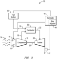
- FIG. 3 illustrates a schematic of an exemplary gas turbine system 10, certain components of which may be referred to herein as an engine, and which may benefit from aspects of the invention. It will be recognized that embodiments of the invention may be used with various gas turbine or other power generation systems.
- System 10 may include a compressor 12 for inletting ambient air flow 14, which may be regulated by inlet guide vanes (IGV) 16 to control air flow to compressor 12 and in turn to a combustor 20.
- Compressed air 18 may be provided to combustor 20, and combustion gas 22 may be provided to a turbine 24 where energy is extracted to turn a shaft 26.
- Shaft 26 may power the compressor 12 and auxiliary equipment, such as an electrical generator (not shown).
- System 10 may include a fuel system 30, which in one example embodiment may provide at least one controllable flow of combustible fuel 32 to combustor 20.
- a controller 40 may be provided in the form of a processor or computer with executable instructions, a digital or analog control system, or other device for receiving input signals or data packets, processing data, executing instructions, producing appropriate output signals and transmitting data packets. Controller 40 may be configured with appropriate control modules and databases to execute various aspects of the invention. In one example embodiment, controller 40 may be responsive to at least one parameter to control an air-to-fuel ratio. During a transient such as a ramping condition of the engine, a measured value of such parameter comprises a time lag affecting at least one control setting during the transient condition of the engine. In accordance with aspects of the present invention, controller 40 may be programmed to predictively determine a correction, such as an engine exhaust temperature (Texh) bias, to correct such control settings.
- Texh engine exhaust temperature
- controller 40 provides engine control that in part may be based on engine Texh measurements.
- controller 40 may be referred to as an outlet temperature control (OTC) controller and such parameter may comprise a measured engine exhaust temperature, as may be measured by a temperature sensor 42, such as a thermocouple.
- OTC outlet temperature control
- a temperature sensor 42 such as a thermocouple.
- OTC outlet temperature control
- engine exhaust temperature measurement need not be limited to an engine exhaust location.
- such measurement may comprise a blade path temperature measurement, or similar measurements.
- a determination of the bias is based at least in part on a ramp rate of the engine during the transient condition of the engine and the time lag of the measured engine exhaust temperature.
- the bias may be applied to a steady-state engine Texh value at a present engine condition.
- the engine exhaust temperature bias is proportional to the ramp rate of the engine, the lag time value, and a differential of engine exhaust temperature values at the present engine condition and the target engine condition. For example, if the lag was left uncorrected, the controller may not appropriately determine that the engine has in fact reached a target condition and the controller may attempt for the IGV and/or fuel flow settings to compensate for this erroneous determination till the lag value of the measured engine exhaust temperature eventually catches up.
- This bias essentially defines a new pseudo engine state for the ramping condition by predicting a condition where the engine neither overfires nor underfires from the steady state values and hence avoids combustion instabilities and high emissions.
- control logic tables may be developed as shown in Table 1 below.
- such control logic tables essentially function as a bias adjustor 44 configured to adjust the bias determined by controller 40 as a function of ambient temperature and/or engine load.
- Table 1 Bias Adjustor Tambient Texh, bias % Load Multiplier for Texh,bias 0 x 10 x 10 x 20 x 20 x 30 x 50 x 100 x
- One example control setting that may corrected based on the determined bias may be a control setting to position inlet guide vanes 16 during the transient condition of the engine.
- Another example control setting that may corrected may be controlling a demand for controllable flow of combustible fuel 32 to combustor 20 during the transient condition of the engine.
- aspects of an example inventive apparatus --as may be used in gas turbine engines during transient conditions for removing or at least substantially reducing the effects of a lag in a measured engine exhaust temperature - and methods disclosed herein may be implemented by any appropriate processor system using any appropriate programming language or programming technique.
- the system can take the form of any appropriate circuitry, such as may involve a hardware embodiment, a software embodiment or an embodiment comprising both hardware and software elements.
- the system may be implemented by way of software and hardware (e.g., processor, sensors, etc.), which may include but is not limited to firmware, resident software, microcode, etc.
- parts of the processor system can take the form of a computer program product accessible from a computer-usable or computer-readable medium providing program code for use by or in connection with a computer or any instruction execution system.
- Examples of computer-readable media may include non-transitory tangible computer-readable media, such as a semiconductor or solid-state memory, magnetic tape, a removable computer diskette, a random access memory (RAM), a read-only memory (ROM), a rigid magnetic disk and an optical disk.
- Current examples of optical disks include compact disk--read only memory (CD-ROM), compact disk-read/write (CD-R/W) and DVD.
- An interface display may be a tablet, flat panel display, PDA, or the like.
Landscapes
- Engineering & Computer Science (AREA)
- Chemical & Material Sciences (AREA)
- Combustion & Propulsion (AREA)
- Mechanical Engineering (AREA)
- General Engineering & Computer Science (AREA)
- Physics & Mathematics (AREA)
- Fluid Mechanics (AREA)
- Control Of Turbines (AREA)
- Combined Controls Of Internal Combustion Engines (AREA)
- Supercharger (AREA)
- Control Of Positive-Displacement Air Blowers (AREA)
Claims (11)
- Steuerungssystem (10) für ein Gasturbinen-(24)-aggregat, umfassend:eine Steuerung (40), die auf mindestens einen Parameter zum Steuern eines Luft-Kraftstoff-Verhältnisse reagiert, wobei während eines Übergangszustandes des Aggregats ein gemessener Wert des mindestens einen Parameters eine Zeitverzögerung umfasst, die mindestens eine Steuereinstellung während des Übergangszustandes des Aggregats beeinflusst, wobei die Steuerung (40) dazu programmiert ist, prädiktiv eine Vorspannung zum Korrigieren der mindestens einen Steuereinstellung zu bestimmen, dadurch gekennzeichnet, dassdie Zeitverzögerung eine Zeitdifferenz zwischen einer idealisierten Aggregatabgastemperaturantwort und einer gemessenen Aggregatabgastemperaturantwort während des Übergangszustandes des Aggregats ist, wobei die Steuerung (40) eine Steuerung bereitstellt, die teilweise auf Aggregatabgastemperaturmessungen basiert, und der mindestens eine Parameter eine gemessene Aggregatabgastemperatur umfasst,und wobei eine Bestimmung der Vorspannung zumindest teilweise auf einer Rampenrate des Aggregats während des Übergangszustandes und der Zeitverzögerung der gemessenen Aggregatabgastemperatur basiert.
- Steuerungssystem (10) nach Anspruch 1, wobei die Vorspannung auf einen stationären Abgastemperaturwert bei einem aktuellen Aggregatzustand angewendet wird.
- Steuerungssystem (10) nach Anspruch 1, wobei die Bestimmung der Vorspannung auf der folgenden Gleichung basiert:
 Texh bias,1 = Vorspannung auf einen stationären Wert der Abgastemperatur (Texh) bei einem aktuellen Aggregatzustand,Texh SS,1 = der stationäre Texh-Wert beim aktuellen Aggregatzustand,TexhSS,2 = ein stationärer Texh-Wert bei einem Ziel-Aggregatzustand,MWrate = Rampenrate des Aggregats,dtlag = Wert der Verzögerungszeit,a = ein Proportionalitätsfaktor, undb = eine standortspezifische Konstante.
 - Steuerungssystem (10) nach Anspruch 1, ferner umfassend Einlassleitschaufeln (16) zum Steuern des Einlassluftstroms (14) zu einem Verdichter (12), wobei die mindestens eine Steuereinstellung eine Steuereinstellung zum Positionieren der Einlassleitschaufeln (16) während des Übergangszustandes des Aggregats umfasst.
- Steuerungssystem (10) nach Anspruch 1, ferner umfassend ein Brennstoffsystem (30) zum Steuern mindestens eines Brennstoffstroms (32) zu einer Brennkammer (20), wobei die mindestens eine Steuereinstellung ferner eine Anforderung für den mindestens einen Brennstoffstrom umfasst.
- Steuerungssystem (10) nach Anspruch 1, ferner umfassend einen Vorspannungseinsteller (44), der dafür ausgelegt ist, die Vorspannung als ein beliebiges von einer Funktion der Umgebungstemperatur, einer Funktion der Aggregatlast und einer Funktion der Umgebungstemperatur und/oder der Aggregatlast einzustellen.
- Verfahren zum Steuern eines Gasturbinenaggregats, wobei das Verfahren umfasst: Steuern eines Luft-Kraftstoff-Verhältnisses mit einer Steuerung (40), die auf mindestens einen Parameter reagiert;Messen eines Wertes des mindestens einen Parameters, der während eines Übergangszustandes des Aggregats eine Zeitverzögerung umfasst, die mindestens eine Steuereinstellung während des Übergangszustandes des Aggregats beeinflusst; undprädiktives Bestimmen einer Vorspannung zum Korrigieren der mindestens einen Steuereinstellung,dadurch gekennzeichnet, dassdie Zeitverzögerung eine Zeitdifferenz zwischen einer idealisierten Aggregatabgastemperaturantwort und einer gemessenen Aggregatabgastemperaturantwort während des Übergangszustandes des Aggregats ist, wobei das Steuern Steuern umfasst, das teilweise auf Aggregatabgastemperaturmessungen basiert, und der mindestens eine Parameter eine gemessene Aggregatabgastemperatur umfasst, und wobei das Bestimmen der Vorspannung zumindest teilweise auf einer Rampenrate des Aggregats während des Übergangszustandes und der Zeitverzögerung der gemessenen Aggregatabgastemperatur basiert.
- Verfahren nach Anspruch 7, ferner umfassend das Anwenden der Vorspannung auf einen stationären Abgastemperaturwert bei einem aktuellen Aggregatzustand.
- Verfahren nach Anspruch 7, wobei das Bestimmen der Vorspannung auf der folgenden Gleichung basiert:
 Texh bias,1 = Vorspannung auf einen stationären Wert der Abgastemperatur (Texh) bei einem aktuellen Aggregatzustand,Texh SS,1 = der stationäre Texh-Wert beim aktuellen Aggregatzustand,TexhSS,2 = ein stationärer Texh-Wert bei einem Ziel-Aggregatzustand,MWrate = Rampenrate des Aggregats,Δtlag = Wert der Verzögerungszeit,a = ein Proportionalitätsfaktor, undb = eine standortspezifische Konstante.
 - Verfahren nach Anspruch 7, ferner umfassend das Steuern eines beliebigen Einlassluftstroms (14) zu einem Verdichter (12) mit Einlassleitschaufeln (16), wobei die mindestens eine Steuereinstellung eine Steuereinstellung zum Positionieren der Einlassleitschaufeln (16) während des Übergangszustandes des Aggregats und mindestens einen Brennstoffstrom zu einer Brennkammer (20) umfasst, wobei die mindestens eine Steuereinstellung ferner eine Anforderung für den mindestens einen Brennstoffstrom umfasst.
- Verfahren nach Anspruch 7, wobei die Vorspannung als ein beliebiges von einer Funktion der Umgebungstemperatur und einer Funktion der Aggregatlast eingestellt wird.
Applications Claiming Priority (2)
| Application Number | Priority Date | Filing Date | Title |
|---|---|---|---|
| US14/140,606 US9850823B2 (en) | 2013-12-26 | 2013-12-26 | Control system and method for controlling a gas turbine engine during transients |
| PCT/US2014/070715 WO2015100081A1 (en) | 2013-12-26 | 2014-12-17 | A control system and method for controlling a gas turbine engine during transients |
Publications (2)
| Publication Number | Publication Date |
|---|---|
| EP3087268A1 EP3087268A1 (de) | 2016-11-02 |
| EP3087268B1 true EP3087268B1 (de) | 2023-03-01 |
Family
ID=52278846
Family Applications (1)
| Application Number | Title | Priority Date | Filing Date |
|---|---|---|---|
| EP14822030.4A Active EP3087268B1 (de) | 2013-12-26 | 2014-12-17 | Steuerungssystem und verfahren zur steuerung einer gasturbine während der transienten |
Country Status (5)
| Country | Link |
|---|---|
| US (1) | US9850823B2 (de) |
| EP (1) | EP3087268B1 (de) |
| JP (1) | JP6306192B2 (de) |
| CN (1) | CN106062343B (de) |
| WO (1) | WO2015100081A1 (de) |
Families Citing this family (9)
| Publication number | Priority date | Publication date | Assignee | Title |
|---|---|---|---|---|
| ES2973287T3 (es) | 2013-09-26 | 2024-06-19 | Wellhead Power Solutions Llc | Sistema y método energético híbridos |
| US9722426B2 (en) | 2013-09-26 | 2017-08-01 | Wellhead Electric Company, Inc. | Hybrid energy system and method |
| US11384939B2 (en) * | 2014-04-21 | 2022-07-12 | Southwest Research Institute | Air-fuel micromix injector having multibank ports for adaptive cooling of high temperature combustor |
| JP7015114B2 (ja) * | 2017-03-29 | 2022-02-02 | 三菱重工業株式会社 | 運転管理装置、発電プラント、発電プラントの運転管理方法 |
| US10822104B2 (en) | 2017-08-29 | 2020-11-03 | Pratt & Whitney Canada Corp. | Variable geometries transient control logic |
| EP3804074A4 (de) * | 2018-06-04 | 2022-02-23 | Wellhead Power Solutions, LLC | Hybrides energiesystem und verfahren |
| US11486316B2 (en) | 2018-09-13 | 2022-11-01 | Pratt & Whitney Canada Corp. | Method and system for adjusting a variable geometry mechanism |
| US11286855B2 (en) | 2019-03-15 | 2022-03-29 | General Electric Company | Systems and methods for operating a turbine engine |
| GB202203716D0 (en) * | 2022-03-17 | 2022-05-04 | Rolls Royce Plc | Methods and systems for controlling an engine system of a vehicle |
Family Cites Families (50)
| Publication number | Priority date | Publication date | Assignee | Title |
|---|---|---|---|---|
| US3173242A (en) * | 1962-01-10 | 1965-03-16 | Nordberg Manufacturing Co | Air-fuel ratio controls for engines |
| US3673796A (en) * | 1970-03-03 | 1972-07-04 | Caterpillar Tractor Co | Anticipating air injection system for turbocharged engines |
| DE2064340C3 (de) * | 1970-12-29 | 1973-12-06 | Motoren- Und Turbinen-Union Muenchen Gmbh, 8000 Muenchen | Regeleinrichtung für eine Gasturbi nenanlage |
| US3956883A (en) * | 1974-08-08 | 1976-05-18 | Westinghouse Electric Corporation | Smooth and highly responsive gas turbine temperature limit control especially useful in combined cycle electric power plants |
| US3979904A (en) * | 1974-08-08 | 1976-09-14 | Westinghouse Electric Corporation | Combined cycle electric power plant and a gas turbine having improved liquid fuel flow detection |
| US4055997A (en) * | 1976-09-15 | 1977-11-01 | United Technologies Corporation | Means for calculating turbine inlet temperature of a gas turbine engine |
| US4242592A (en) * | 1977-10-11 | 1980-12-30 | Westinghouse Electric Corp. | Gas turbine power plant control apparatus including an ambient temperature responsive control system |
| US4259835A (en) * | 1978-02-06 | 1981-04-07 | Westinghouse Electric Corp. | System and method for monitoring industrial gas turbine operating parameters and for providing gas turbine power plant control system inputs representative thereof |
| US4292806A (en) * | 1979-02-28 | 1981-10-06 | Semco Instruments, Inc. | Turbocharger control system |
| US4550565A (en) * | 1984-01-16 | 1985-11-05 | Tokyo Shibaura Denki Kabushiki Kaisha | Gas turbine control systems |
| US4700542A (en) * | 1984-09-21 | 1987-10-20 | Wang Lin Shu | Internal combustion engines and methods of operation |
| US5095221A (en) * | 1989-11-03 | 1992-03-10 | Westinghouse Electric Corp. | Gas turbine control system having partial hood control |
| US5103629A (en) * | 1989-11-20 | 1992-04-14 | Westinghouse Electric Corp. | Gas turbine control system having optimized ignition air flow control |
| US5252860A (en) * | 1989-12-11 | 1993-10-12 | Westinghouse Electric Corp. | Gas turbine control system having maximum instantaneous load-pickup limiter |
| US5487265A (en) * | 1994-05-02 | 1996-01-30 | General Electric Company | Gas turbine coordinated fuel-air control method and apparatus therefor |
| US6230683B1 (en) * | 1997-08-22 | 2001-05-15 | Cummins Engine Company, Inc. | Premixed charge compression ignition engine with optimal combustion control |
| JPH10238339A (ja) * | 1997-02-20 | 1998-09-08 | Nissan Motor Co Ltd | エンジンの排気浄化装置 |
| US5896736A (en) * | 1997-03-06 | 1999-04-27 | General Electric Company | Load rejection rapid acting fuel-air controller for gas turbine |
| US6379038B1 (en) * | 1998-06-22 | 2002-04-30 | Ralph A. Felice | Temperature determining device and process |
| US6612292B2 (en) * | 2001-01-09 | 2003-09-02 | Nissan Motor Co., Ltd. | Fuel injection control for diesel engine |
| JP2003065130A (ja) * | 2001-08-30 | 2003-03-05 | Hitachi Ltd | 混合気供給装置の診断装置及びその診断方法 |
| JP3649188B2 (ja) * | 2002-01-16 | 2005-05-18 | トヨタ自動車株式会社 | 排気浄化装置付き内燃機関 |
| US6715295B2 (en) * | 2002-05-22 | 2004-04-06 | Siemens Westinghouse Power Corporation | Gas turbine pilot burner water injection and method of operation |
| DE10225305A1 (de) * | 2002-06-07 | 2003-12-18 | Bosch Gmbh Robert | Verfahren und Vorrichtung zur Steuerung einer Brennkraftmaschine |
| US6694742B2 (en) * | 2002-06-26 | 2004-02-24 | General Electric Company | Gas turbine system operation based on estimated stress |
| JP2004108315A (ja) * | 2002-09-20 | 2004-04-08 | Toshiba Corp | ガスタービンシステムおよびその運転方法 |
| US7643928B2 (en) * | 2004-01-05 | 2010-01-05 | Bombardier Transportation Gmbh | System and method for controlling the speed of a gas turbine engine |
| US7269953B2 (en) * | 2004-08-27 | 2007-09-18 | Siemens Power Generation, Inc. | Method of controlling a power generation system |
| JP4699130B2 (ja) * | 2005-08-03 | 2011-06-08 | 三菱重工業株式会社 | ガスタービンの入口案内翼制御装置 |
| US7549292B2 (en) * | 2005-10-03 | 2009-06-23 | General Electric Company | Method of controlling bypass air split to gas turbine combustor |
| US7481061B2 (en) * | 2005-11-10 | 2009-01-27 | Siemens Energy, Inc. | Fuel control for starting a gas turbine engine |
| JP2008051092A (ja) * | 2006-07-25 | 2008-03-06 | Nissan Motor Co Ltd | 内燃機関の排気系保護装置及び保護方法 |
| US8474268B2 (en) * | 2007-08-16 | 2013-07-02 | General Electric Company | Method of mitigating undesired gas turbine transient response using event based actions |
| JP4838785B2 (ja) | 2007-11-06 | 2011-12-14 | 三菱重工業株式会社 | ガスタービンの運転制御装置および運転制御方法 |
| US7966802B2 (en) * | 2008-02-05 | 2011-06-28 | General Electric Company | Methods and apparatus for operating gas turbine engine systems |
| US8205606B2 (en) * | 2008-07-03 | 2012-06-26 | International Engine Intellectual Property Company, Llc | Model for inferring temperature of exhaust gas at an exhaust manifold using temperature measured at entrance of a diesel oxidation catalyst |
| US9354618B2 (en) * | 2009-05-08 | 2016-05-31 | Gas Turbine Efficiency Sweden Ab | Automated tuning of multiple fuel gas turbine combustion systems |
| JP4852127B2 (ja) * | 2009-06-25 | 2012-01-11 | 日立建機株式会社 | 作業機械 |
| US8215095B2 (en) * | 2009-10-26 | 2012-07-10 | General Electric Company | Model-based coordinated air-fuel control for a gas turbine |
| US8555653B2 (en) * | 2009-12-23 | 2013-10-15 | General Electric Company | Method for starting a turbomachine |
| US7915868B1 (en) * | 2009-12-23 | 2011-03-29 | General Electric Company | Method of synchronizing a turbomachine generator to an electric grid |
| JP5143170B2 (ja) * | 2010-03-17 | 2013-02-13 | 日立オートモティブシステムズ株式会社 | 内燃機関の制御方法 |
| US8171717B2 (en) * | 2010-05-14 | 2012-05-08 | General Electric Company | Model-based coordinated air-fuel control for a gas turbine |
| JP5635948B2 (ja) * | 2010-07-23 | 2014-12-03 | 三菱日立パワーシステムズ株式会社 | 燃焼器の制御方法及び制御装置 |
| US8783013B2 (en) * | 2010-10-21 | 2014-07-22 | Siemens Energy, Inc. | Feedforward selective catalytic reduction system for turbine engines |
| JP5578028B2 (ja) * | 2010-10-29 | 2014-08-27 | セイコーエプソン株式会社 | 温度測定装置および温度測定方法 |
| US9297316B2 (en) * | 2011-11-23 | 2016-03-29 | General Electric Company | Method and apparatus for optimizing the operation of a turbine system under flexible loads |
| US10107495B2 (en) * | 2012-11-02 | 2018-10-23 | General Electric Company | Gas turbine combustor control system for stoichiometric combustion in the presence of a diluent |
| US9383742B2 (en) * | 2013-03-08 | 2016-07-05 | Pratt & Whitney Canada Corp. | System and method for positioning error compensation during manufacturing of complex-shaped gas turbine engine parts |
| SE538375C2 (sv) * | 2013-05-22 | 2016-05-31 | Scania Cv Ab | Förfarande och anordning för att effektivisera motordrift hos ett motorfordon baserat på en förändring hos åtminstone enav parametrarna avgastemperatur, kylmedeltemperatur och smörjmedeltemperatur |
-
2013
- 2013-12-26 US US14/140,606 patent/US9850823B2/en active Active
-
2014
- 2014-12-17 EP EP14822030.4A patent/EP3087268B1/de active Active
- 2014-12-17 CN CN201480071392.9A patent/CN106062343B/zh active Active
- 2014-12-17 JP JP2016543038A patent/JP6306192B2/ja active Active
- 2014-12-17 WO PCT/US2014/070715 patent/WO2015100081A1/en not_active Ceased
Also Published As
| Publication number | Publication date |
|---|---|
| CN106062343B (zh) | 2018-07-17 |
| CN106062343A (zh) | 2016-10-26 |
| WO2015100081A1 (en) | 2015-07-02 |
| EP3087268A1 (de) | 2016-11-02 |
| US9850823B2 (en) | 2017-12-26 |
| JP6306192B2 (ja) | 2018-04-04 |
| JP2017502206A (ja) | 2017-01-19 |
| US20150184611A1 (en) | 2015-07-02 |
Similar Documents
| Publication | Publication Date | Title |
|---|---|---|
| EP3087268B1 (de) | Steuerungssystem und verfahren zur steuerung einer gasturbine während der transienten | |
| US6912856B2 (en) | Method and system for controlling gas turbine by adjusting target exhaust temperature | |
| US6742341B2 (en) | Automatic combustion control for a gas turbine | |
| KR101690444B1 (ko) | 가스 터빈 시스템, 제어 장치 및 가스 터빈 운전 방법 | |
| CN101900033B (zh) | 用于改进燃气涡轮性能的系统和方法 | |
| JP6331138B2 (ja) | 流量比算出装置、これを備えている制御装置、この制御装置を備えているガスタービンプラント、流量比算出方法、及び燃料系統の制御方法 | |
| WO2011139567A1 (en) | Selecting and applying to fuel-flow splits bias values to correct for elevated inlet air humidity | |
| JPWO2012105053A1 (ja) | ガスタービン発電プラントの制御装置 | |
| EP2902606B1 (de) | Verfahren zum Betreiben einer Gasturbine in Teillast | |
| US20150040571A1 (en) | Method for fuel split control to a gas turbine using a modified turbine firing temperature | |
| JP2010285955A (ja) | ガスタービンの制御装置及び発電システム | |
| CN105392977B (zh) | 用于生成要注入涡轮引擎的燃烧室的燃料流的命令的方法和设备 | |
| CN108779715A (zh) | 燃气轮机的控制装置以及燃气轮机的控制方法 | |
| US10436124B2 (en) | Signal processing for auto-tuning a gas turbine engine | |
| US20150068215A1 (en) | Two-Shaft Gas Turbine | |
| EP3165741A1 (de) | System und verfahren zur bestimmung von kraftstoffspaltungen für eine gasturbine | |
| EP2846024B1 (de) | Verfahren zur Steuerung einer Gasturbinengruppe | |
| JP2013160154A (ja) | ガスタービン制御装置及び方法並びにプログラム、それを用いた発電プラント | |
| US9002617B2 (en) | Gas turbine engine controller with event trigger | |
| KR101143728B1 (ko) | 가스터빈의 질소산화물 농도 자동 제어장치 | |
| JP2021167593A (ja) | ガスタービン制御装置、ガスタービン制御方法、及び、ガスタービン制御プログラム | |
| CN108119237B (zh) | 无模型燃烧动力自动调谐 | |
| US20180371936A1 (en) | Method and system for schedule predictive lead compensation | |
| EP2249006A1 (de) | Vorrichtung und Verfahren zur Regelung der Abgastemperatur einer Kraftwerks-Gasturbine | |
| US12031490B2 (en) | System and method for non-model based control utilizing turbine exit mach number surrogate |
Legal Events
| Date | Code | Title | Description |
|---|---|---|---|
| PUAI | Public reference made under article 153(3) epc to a published international application that has entered the european phase |
Free format text: ORIGINAL CODE: 0009012 |
|
| 17P | Request for examination filed |
Effective date: 20160624 |
|
| AK | Designated contracting states |
Kind code of ref document: A1 Designated state(s): AL AT BE BG CH CY CZ DE DK EE ES FI FR GB GR HR HU IE IS IT LI LT LU LV MC MK MT NL NO PL PT RO RS SE SI SK SM TR |
|
| AX | Request for extension of the european patent |
Extension state: BA ME |
|
| DAX | Request for extension of the european patent (deleted) | ||
| RAP1 | Party data changed (applicant data changed or rights of an application transferred) |
Owner name: SIEMENS AKTIENGESELLSCHAFT |
|
| STAA | Information on the status of an ep patent application or granted ep patent |
Free format text: STATUS: EXAMINATION IS IN PROGRESS |
|
| 17Q | First examination report despatched |
Effective date: 20190604 |
|
| RAP1 | Party data changed (applicant data changed or rights of an application transferred) |
Owner name: SIEMENS ENERGY GLOBAL GMBH & CO. KG |
|
| GRAP | Despatch of communication of intention to grant a patent |
Free format text: ORIGINAL CODE: EPIDOSNIGR1 |
|
| STAA | Information on the status of an ep patent application or granted ep patent |
Free format text: STATUS: GRANT OF PATENT IS INTENDED |
|
| INTG | Intention to grant announced |
Effective date: 20221027 |
|
| GRAS | Grant fee paid |
Free format text: ORIGINAL CODE: EPIDOSNIGR3 |
|
| GRAA | (expected) grant |
Free format text: ORIGINAL CODE: 0009210 |
|
| STAA | Information on the status of an ep patent application or granted ep patent |
Free format text: STATUS: THE PATENT HAS BEEN GRANTED |
|
| AK | Designated contracting states |
Kind code of ref document: B1 Designated state(s): AL AT BE BG CH CY CZ DE DK EE ES FI FR GB GR HR HU IE IS IT LI LT LU LV MC MK MT NL NO PL PT RO RS SE SI SK SM TR |
|
| REG | Reference to a national code |
Ref country code: GB Ref legal event code: FG4D |
|
| REG | Reference to a national code |
Ref country code: CH Ref legal event code: EP Ref country code: AT Ref legal event code: REF Ref document number: 1551124 Country of ref document: AT Kind code of ref document: T Effective date: 20230315 |
|
| REG | Reference to a national code |
Ref country code: DE Ref legal event code: R096 Ref document number: 602014086352 Country of ref document: DE |
|
| REG | Reference to a national code |
Ref country code: IE Ref legal event code: FG4D |
|
| REG | Reference to a national code |
Ref country code: LT Ref legal event code: MG9D |
|
| REG | Reference to a national code |
Ref country code: NL Ref legal event code: MP Effective date: 20230301 |
|
| PG25 | Lapsed in a contracting state [announced via postgrant information from national office to epo] |
Ref country code: RS Free format text: LAPSE BECAUSE OF FAILURE TO SUBMIT A TRANSLATION OF THE DESCRIPTION OR TO PAY THE FEE WITHIN THE PRESCRIBED TIME-LIMIT Effective date: 20230301 Ref country code: NO Free format text: LAPSE BECAUSE OF FAILURE TO SUBMIT A TRANSLATION OF THE DESCRIPTION OR TO PAY THE FEE WITHIN THE PRESCRIBED TIME-LIMIT Effective date: 20230601 Ref country code: LV Free format text: LAPSE BECAUSE OF FAILURE TO SUBMIT A TRANSLATION OF THE DESCRIPTION OR TO PAY THE FEE WITHIN THE PRESCRIBED TIME-LIMIT Effective date: 20230301 Ref country code: LT Free format text: LAPSE BECAUSE OF FAILURE TO SUBMIT A TRANSLATION OF THE DESCRIPTION OR TO PAY THE FEE WITHIN THE PRESCRIBED TIME-LIMIT Effective date: 20230301 Ref country code: HR Free format text: LAPSE BECAUSE OF FAILURE TO SUBMIT A TRANSLATION OF THE DESCRIPTION OR TO PAY THE FEE WITHIN THE PRESCRIBED TIME-LIMIT Effective date: 20230301 Ref country code: ES Free format text: LAPSE BECAUSE OF FAILURE TO SUBMIT A TRANSLATION OF THE DESCRIPTION OR TO PAY THE FEE WITHIN THE PRESCRIBED TIME-LIMIT Effective date: 20230301 |
|
| REG | Reference to a national code |
Ref country code: AT Ref legal event code: MK05 Ref document number: 1551124 Country of ref document: AT Kind code of ref document: T Effective date: 20230301 |
|
| PG25 | Lapsed in a contracting state [announced via postgrant information from national office to epo] |
Ref country code: SE Free format text: LAPSE BECAUSE OF FAILURE TO SUBMIT A TRANSLATION OF THE DESCRIPTION OR TO PAY THE FEE WITHIN THE PRESCRIBED TIME-LIMIT Effective date: 20230301 Ref country code: PL Free format text: LAPSE BECAUSE OF FAILURE TO SUBMIT A TRANSLATION OF THE DESCRIPTION OR TO PAY THE FEE WITHIN THE PRESCRIBED TIME-LIMIT Effective date: 20230301 Ref country code: NL Free format text: LAPSE BECAUSE OF FAILURE TO SUBMIT A TRANSLATION OF THE DESCRIPTION OR TO PAY THE FEE WITHIN THE PRESCRIBED TIME-LIMIT Effective date: 20230301 Ref country code: GR Free format text: LAPSE BECAUSE OF FAILURE TO SUBMIT A TRANSLATION OF THE DESCRIPTION OR TO PAY THE FEE WITHIN THE PRESCRIBED TIME-LIMIT Effective date: 20230602 Ref country code: FI Free format text: LAPSE BECAUSE OF FAILURE TO SUBMIT A TRANSLATION OF THE DESCRIPTION OR TO PAY THE FEE WITHIN THE PRESCRIBED TIME-LIMIT Effective date: 20230301 |
|
| PG25 | Lapsed in a contracting state [announced via postgrant information from national office to epo] |
Ref country code: SM Free format text: LAPSE BECAUSE OF FAILURE TO SUBMIT A TRANSLATION OF THE DESCRIPTION OR TO PAY THE FEE WITHIN THE PRESCRIBED TIME-LIMIT Effective date: 20230301 Ref country code: RO Free format text: LAPSE BECAUSE OF FAILURE TO SUBMIT A TRANSLATION OF THE DESCRIPTION OR TO PAY THE FEE WITHIN THE PRESCRIBED TIME-LIMIT Effective date: 20230301 Ref country code: PT Free format text: LAPSE BECAUSE OF FAILURE TO SUBMIT A TRANSLATION OF THE DESCRIPTION OR TO PAY THE FEE WITHIN THE PRESCRIBED TIME-LIMIT Effective date: 20230703 Ref country code: EE Free format text: LAPSE BECAUSE OF FAILURE TO SUBMIT A TRANSLATION OF THE DESCRIPTION OR TO PAY THE FEE WITHIN THE PRESCRIBED TIME-LIMIT Effective date: 20230301 Ref country code: CZ Free format text: LAPSE BECAUSE OF FAILURE TO SUBMIT A TRANSLATION OF THE DESCRIPTION OR TO PAY THE FEE WITHIN THE PRESCRIBED TIME-LIMIT Effective date: 20230301 Ref country code: AT Free format text: LAPSE BECAUSE OF FAILURE TO SUBMIT A TRANSLATION OF THE DESCRIPTION OR TO PAY THE FEE WITHIN THE PRESCRIBED TIME-LIMIT Effective date: 20230301 |
|
| PG25 | Lapsed in a contracting state [announced via postgrant information from national office to epo] |
Ref country code: SK Free format text: LAPSE BECAUSE OF FAILURE TO SUBMIT A TRANSLATION OF THE DESCRIPTION OR TO PAY THE FEE WITHIN THE PRESCRIBED TIME-LIMIT Effective date: 20230301 Ref country code: IS Free format text: LAPSE BECAUSE OF FAILURE TO SUBMIT A TRANSLATION OF THE DESCRIPTION OR TO PAY THE FEE WITHIN THE PRESCRIBED TIME-LIMIT Effective date: 20230701 |
|
| REG | Reference to a national code |
Ref country code: DE Ref legal event code: R097 Ref document number: 602014086352 Country of ref document: DE |
|
| PLBE | No opposition filed within time limit |
Free format text: ORIGINAL CODE: 0009261 |
|
| STAA | Information on the status of an ep patent application or granted ep patent |
Free format text: STATUS: NO OPPOSITION FILED WITHIN TIME LIMIT |
|
| PG25 | Lapsed in a contracting state [announced via postgrant information from national office to epo] |
Ref country code: SI Free format text: LAPSE BECAUSE OF FAILURE TO SUBMIT A TRANSLATION OF THE DESCRIPTION OR TO PAY THE FEE WITHIN THE PRESCRIBED TIME-LIMIT Effective date: 20230301 Ref country code: DK Free format text: LAPSE BECAUSE OF FAILURE TO SUBMIT A TRANSLATION OF THE DESCRIPTION OR TO PAY THE FEE WITHIN THE PRESCRIBED TIME-LIMIT Effective date: 20230301 |
|
| 26N | No opposition filed |
Effective date: 20231204 |
|
| REG | Reference to a national code |
Ref country code: CH Ref legal event code: PL |
|
| PG25 | Lapsed in a contracting state [announced via postgrant information from national office to epo] |
Ref country code: LU Free format text: LAPSE BECAUSE OF NON-PAYMENT OF DUE FEES Effective date: 20231217 |
|
| PG25 | Lapsed in a contracting state [announced via postgrant information from national office to epo] |
Ref country code: MC Free format text: LAPSE BECAUSE OF FAILURE TO SUBMIT A TRANSLATION OF THE DESCRIPTION OR TO PAY THE FEE WITHIN THE PRESCRIBED TIME-LIMIT Effective date: 20230301 |
|
| REG | Reference to a national code |
Ref country code: BE Ref legal event code: MM Effective date: 20231231 |
|
| PG25 | Lapsed in a contracting state [announced via postgrant information from national office to epo] |
Ref country code: MC Free format text: LAPSE BECAUSE OF FAILURE TO SUBMIT A TRANSLATION OF THE DESCRIPTION OR TO PAY THE FEE WITHIN THE PRESCRIBED TIME-LIMIT Effective date: 20230301 Ref country code: LU Free format text: LAPSE BECAUSE OF NON-PAYMENT OF DUE FEES Effective date: 20231217 |
|
| REG | Reference to a national code |
Ref country code: IE Ref legal event code: MM4A |
|
| PG25 | Lapsed in a contracting state [announced via postgrant information from national office to epo] |
Ref country code: IE Free format text: LAPSE BECAUSE OF NON-PAYMENT OF DUE FEES Effective date: 20231217 |
|
| PG25 | Lapsed in a contracting state [announced via postgrant information from national office to epo] |
Ref country code: BE Free format text: LAPSE BECAUSE OF NON-PAYMENT OF DUE FEES Effective date: 20231231 |
|
| PG25 | Lapsed in a contracting state [announced via postgrant information from national office to epo] |
Ref country code: CH Free format text: LAPSE BECAUSE OF NON-PAYMENT OF DUE FEES Effective date: 20231231 |
|
| PG25 | Lapsed in a contracting state [announced via postgrant information from national office to epo] |
Ref country code: IE Free format text: LAPSE BECAUSE OF NON-PAYMENT OF DUE FEES Effective date: 20231217 Ref country code: CH Free format text: LAPSE BECAUSE OF NON-PAYMENT OF DUE FEES Effective date: 20231231 Ref country code: BE Free format text: LAPSE BECAUSE OF NON-PAYMENT OF DUE FEES Effective date: 20231231 |
|
| PG25 | Lapsed in a contracting state [announced via postgrant information from national office to epo] |
Ref country code: BG Free format text: LAPSE BECAUSE OF FAILURE TO SUBMIT A TRANSLATION OF THE DESCRIPTION OR TO PAY THE FEE WITHIN THE PRESCRIBED TIME-LIMIT Effective date: 20230301 |
|
| PG25 | Lapsed in a contracting state [announced via postgrant information from national office to epo] |
Ref country code: BG Free format text: LAPSE BECAUSE OF FAILURE TO SUBMIT A TRANSLATION OF THE DESCRIPTION OR TO PAY THE FEE WITHIN THE PRESCRIBED TIME-LIMIT Effective date: 20230301 |
|
| PG25 | Lapsed in a contracting state [announced via postgrant information from national office to epo] |
Ref country code: CY Free format text: LAPSE BECAUSE OF FAILURE TO SUBMIT A TRANSLATION OF THE DESCRIPTION OR TO PAY THE FEE WITHIN THE PRESCRIBED TIME-LIMIT; INVALID AB INITIO Effective date: 20141217 |
|
| PG25 | Lapsed in a contracting state [announced via postgrant information from national office to epo] |
Ref country code: HU Free format text: LAPSE BECAUSE OF FAILURE TO SUBMIT A TRANSLATION OF THE DESCRIPTION OR TO PAY THE FEE WITHIN THE PRESCRIBED TIME-LIMIT; INVALID AB INITIO Effective date: 20141217 |
|
| PG25 | Lapsed in a contracting state [announced via postgrant information from national office to epo] |
Ref country code: TR Free format text: LAPSE BECAUSE OF FAILURE TO SUBMIT A TRANSLATION OF THE DESCRIPTION OR TO PAY THE FEE WITHIN THE PRESCRIBED TIME-LIMIT Effective date: 20230301 |
|
| PGFP | Annual fee paid to national office [announced via postgrant information from national office to epo] |
Ref country code: GB Payment date: 20251223 Year of fee payment: 12 |
|
| PGFP | Annual fee paid to national office [announced via postgrant information from national office to epo] |
Ref country code: IT Payment date: 20251218 Year of fee payment: 12 |
|
| PGFP | Annual fee paid to national office [announced via postgrant information from national office to epo] |
Ref country code: FR Payment date: 20251223 Year of fee payment: 12 |
|
| PGFP | Annual fee paid to national office [announced via postgrant information from national office to epo] |
Ref country code: DE Payment date: 20251229 Year of fee payment: 12 |