EP3087277B2 - Pompe à liquide entraînée par un moteur électrique en particulier pour la lubrification forcée d'une boîte de vitesses de véhicules automobiles - Google Patents
Pompe à liquide entraînée par un moteur électrique en particulier pour la lubrification forcée d'une boîte de vitesses de véhicules automobiles Download PDFInfo
- Publication number
- EP3087277B2 EP3087277B2 EP14776581.2A EP14776581A EP3087277B2 EP 3087277 B2 EP3087277 B2 EP 3087277B2 EP 14776581 A EP14776581 A EP 14776581A EP 3087277 B2 EP3087277 B2 EP 3087277B2
- Authority
- EP
- European Patent Office
- Prior art keywords
- pump
- housing
- liquid
- housing section
- section
- Prior art date
- Legal status (The legal status is an assumption and is not a legal conclusion. Google has not performed a legal analysis and makes no representation as to the accuracy of the status listed.)
- Active
Links
Images

Classifications
-
- F—MECHANICAL ENGINEERING; LIGHTING; HEATING; WEAPONS; BLASTING
- F04—POSITIVE - DISPLACEMENT MACHINES FOR LIQUIDS; PUMPS FOR LIQUIDS OR ELASTIC FLUIDS
- F04D—NON-POSITIVE-DISPLACEMENT PUMPS
- F04D13/00—Pumping installations or systems
- F04D13/02—Units comprising pumps and their driving means
- F04D13/06—Units comprising pumps and their driving means the pump being electrically driven
- F04D13/0606—Canned motor pumps
-
- F—MECHANICAL ENGINEERING; LIGHTING; HEATING; WEAPONS; BLASTING
- F04—POSITIVE - DISPLACEMENT MACHINES FOR LIQUIDS; PUMPS FOR LIQUIDS OR ELASTIC FLUIDS
- F04D—NON-POSITIVE-DISPLACEMENT PUMPS
- F04D13/00—Pumping installations or systems
- F04D13/02—Units comprising pumps and their driving means
- F04D13/06—Units comprising pumps and their driving means the pump being electrically driven
-
- F—MECHANICAL ENGINEERING; LIGHTING; HEATING; WEAPONS; BLASTING
- F04—POSITIVE - DISPLACEMENT MACHINES FOR LIQUIDS; PUMPS FOR LIQUIDS OR ELASTIC FLUIDS
- F04D—NON-POSITIVE-DISPLACEMENT PUMPS
- F04D15/00—Control, e.g. regulation, of pumps, pumping installations or systems
- F04D15/0088—Testing machines
-
- F—MECHANICAL ENGINEERING; LIGHTING; HEATING; WEAPONS; BLASTING
- F04—POSITIVE - DISPLACEMENT MACHINES FOR LIQUIDS; PUMPS FOR LIQUIDS OR ELASTIC FLUIDS
- F04D—NON-POSITIVE-DISPLACEMENT PUMPS
- F04D15/00—Control, e.g. regulation, of pumps, pumping installations or systems
- F04D15/0094—Indicators of rotational movement
-
- F—MECHANICAL ENGINEERING; LIGHTING; HEATING; WEAPONS; BLASTING
- F04—POSITIVE - DISPLACEMENT MACHINES FOR LIQUIDS; PUMPS FOR LIQUIDS OR ELASTIC FLUIDS
- F04D—NON-POSITIVE-DISPLACEMENT PUMPS
- F04D29/00—Details, component parts, or accessories
- F04D29/08—Sealings
- F04D29/086—Sealings especially adapted for liquid pumps
-
- F—MECHANICAL ENGINEERING; LIGHTING; HEATING; WEAPONS; BLASTING
- F04—POSITIVE - DISPLACEMENT MACHINES FOR LIQUIDS; PUMPS FOR LIQUIDS OR ELASTIC FLUIDS
- F04D—NON-POSITIVE-DISPLACEMENT PUMPS
- F04D29/00—Details, component parts, or accessories
- F04D29/18—Rotors
- F04D29/22—Rotors specially for centrifugal pumps
-
- F—MECHANICAL ENGINEERING; LIGHTING; HEATING; WEAPONS; BLASTING
- F04—POSITIVE - DISPLACEMENT MACHINES FOR LIQUIDS; PUMPS FOR LIQUIDS OR ELASTIC FLUIDS
- F04D—NON-POSITIVE-DISPLACEMENT PUMPS
- F04D29/00—Details, component parts, or accessories
- F04D29/18—Rotors
- F04D29/22—Rotors specially for centrifugal pumps
- F04D29/2205—Conventional flow pattern
-
- F—MECHANICAL ENGINEERING; LIGHTING; HEATING; WEAPONS; BLASTING
- F04—POSITIVE - DISPLACEMENT MACHINES FOR LIQUIDS; PUMPS FOR LIQUIDS OR ELASTIC FLUIDS
- F04D—NON-POSITIVE-DISPLACEMENT PUMPS
- F04D29/00—Details, component parts, or accessories
- F04D29/40—Casings; Connections of working fluid
- F04D29/42—Casings; Connections of working fluid for radial or helico-centrifugal pumps
- F04D29/426—Casings; Connections of working fluid for radial or helico-centrifugal pumps especially adapted for liquid pumps
-
- H—ELECTRICITY
- H02—GENERATION; CONVERSION OR DISTRIBUTION OF ELECTRIC POWER
- H02K—DYNAMO-ELECTRIC MACHINES
- H02K1/00—Details of the magnetic circuit
- H02K1/06—Details of the magnetic circuit characterised by the shape, form or construction
- H02K1/22—Rotating parts of the magnetic circuit
- H02K1/27—Rotor cores with permanent magnets
- H02K1/2706—Inner rotors
-
- H—ELECTRICITY
- H02—GENERATION; CONVERSION OR DISTRIBUTION OF ELECTRIC POWER
- H02K—DYNAMO-ELECTRIC MACHINES
- H02K11/00—Structural association of dynamo-electric machines with electric components or with devices for shielding, monitoring or protection
- H02K11/20—Structural association of dynamo-electric machines with electric components or with devices for shielding, monitoring or protection for measuring, monitoring, testing, protecting or switching
- H02K11/25—Devices for sensing temperature, or actuated thereby
-
- H—ELECTRICITY
- H02—GENERATION; CONVERSION OR DISTRIBUTION OF ELECTRIC POWER
- H02K—DYNAMO-ELECTRIC MACHINES
- H02K29/00—Motors or generators having non-mechanical commutating devices, e.g. discharge tubes or semiconductor devices
- H02K29/06—Motors or generators having non-mechanical commutating devices, e.g. discharge tubes or semiconductor devices with position sensing devices
- H02K29/08—Motors or generators having non-mechanical commutating devices, e.g. discharge tubes or semiconductor devices with position sensing devices using magnetic effect devices, e.g. Hall-plates, magneto-resistors
-
- H—ELECTRICITY
- H02—GENERATION; CONVERSION OR DISTRIBUTION OF ELECTRIC POWER
- H02K—DYNAMO-ELECTRIC MACHINES
- H02K5/00—Casings; Enclosures; Supports
- H02K5/02—Casings or enclosures characterised by the material thereof
-
- H—ELECTRICITY
- H02—GENERATION; CONVERSION OR DISTRIBUTION OF ELECTRIC POWER
- H02K—DYNAMO-ELECTRIC MACHINES
- H02K5/00—Casings; Enclosures; Supports
- H02K5/04—Casings or enclosures characterised by the shape, form or construction thereof
-
- H—ELECTRICITY
- H02—GENERATION; CONVERSION OR DISTRIBUTION OF ELECTRIC POWER
- H02K—DYNAMO-ELECTRIC MACHINES
- H02K5/00—Casings; Enclosures; Supports
- H02K5/04—Casings or enclosures characterised by the shape, form or construction thereof
- H02K5/12—Casings or enclosures characterised by the shape, form or construction thereof specially adapted for operating in liquid or gas
-
- H—ELECTRICITY
- H02—GENERATION; CONVERSION OR DISTRIBUTION OF ELECTRIC POWER
- H02K—DYNAMO-ELECTRIC MACHINES
- H02K5/00—Casings; Enclosures; Supports
- H02K5/04—Casings or enclosures characterised by the shape, form or construction thereof
- H02K5/12—Casings or enclosures characterised by the shape, form or construction thereof specially adapted for operating in liquid or gas
- H02K5/128—Casings or enclosures characterised by the shape, form or construction thereof specially adapted for operating in liquid or gas using air-gap sleeves or air-gap discs
-
- F—MECHANICAL ENGINEERING; LIGHTING; HEATING; WEAPONS; BLASTING
- F16—ENGINEERING ELEMENTS AND UNITS; GENERAL MEASURES FOR PRODUCING AND MAINTAINING EFFECTIVE FUNCTIONING OF MACHINES OR INSTALLATIONS; THERMAL INSULATION IN GENERAL
- F16H—GEARING
- F16H57/00—General details of gearing
- F16H57/04—Features relating to lubrication or cooling or heating
- F16H57/0434—Features relating to lubrication or cooling or heating relating to lubrication supply, e.g. pumps; Pressure control
- F16H57/0436—Pumps
Definitions
- the present invention relates to an electric motor driven liquid pump.
- the invention relates to such a liquid pump as are used in large numbers in modern motor vehicles for the forced lubrication of manual transmissions.
- a gearbox which is arranged in a motor vehicle in a drive train between an internal combustion engine and the vehicle wheels to be driven, has a lubricant system for lubrication with a lubricant, such as transmission oil, which is used to bring the lubricant from a lubricant sump in the transmission housing to points to be lubricated.
- a lubricant such as transmission oil
- the latter include, in particular, meshing gears and bearings for the rotating parts, namely shafts and gears.
- lubricant pumps driven by an electric motor are already used in the prior art (see, for example, the publication DE-A-10 2005 005 154 ).
- the last-mentioned low-pressure lubricant system is the preferred pump field of application here, in particular because it offers cost advantages over the pressure solution.
- a filter arrangement to avoid nozzle clogging is unnecessary, the susceptibility to contamination is lower overall, a weaker motor power can be provided for the electric motor, etc.
- Structural details of a centrifugal pump driven by an electric motor for the lubricant supply of a gear are, for example, the publication DE-A-10 2007 018 504 ( Fig. 7 ) refer to.
- an electric motor and a pump driven by it form a motor-pump unit which is arranged directly in the lubricant (operating medium in the parlance of this publication) below a liquid level.
- the electric motor and the pump are one behind the other, the motor-pump unit also being surrounded by a guide device which serves to feed the suction flow along the surface of the electric motor, which is heated up due to operation, to a suction connection of the pump to lead.
- the thermal contact between the electric motor and the lubricant guided along it is intended to improve the heat transfer and to heat the lubricant, so that its viscosity is reduced and thus also the suction resistance.
- the delivery rate of the pump should increase and thus the amount of lubricant supplied to the lubrication points;
- the intention is to extend the temperature range downwards at which the pump can still reliably deliver lubricant.
- a disadvantage of this prior art is, however, to be seen in the fact that the motor-pump unit with the guide device surrounding it takes up a relatively large installation space both in the radial direction and in the axial direction. However, the available installation space at the bottom of the gearbox housing is usually very tight.
- an electric motor-driven auxiliary oil pump which is arranged within an oil pan of an automatic transmission.
- the pump and the electric motor are located one behind the other, the latter being located outside the oil pan.
- the pump is driven mechanically via a shaft which is passed through the wall of the oil pan and sealed off from this wall.
- This arrangement of the pump and electric motor one behind the other also takes up a relatively large amount of space.
- a brush motor is preferably used, which as such must be arranged outside the oil chamber and is also prone to wear.
- DE-A-199 34 382 and DE-A-199 56 380 Liquid pumps that can be used as cooling water pumps for the cooling circuit / heating circuit of a motor vehicle. These liquid pumps have an integrated electric motor with a stator and a rotor, wherein the stator is a claw pole stator, while the rotor forms an impeller of the pump.
- a magnetic field sensor not shown, can be provided at a location not specified in detail, where it is exposed to the variable magnetic field of the rotating rotor, in particular for commutation of the electric motor.
- a water pump driven by an electric motor is also known, in which a separating wall arranged in a sealing manner between a stator and a rotor unit is formed in a simple and inexpensive manner from a rustproof, deep-drawable material.
- a substantially hollow cone-shaped holding element is formed at the central point of the partition wall, which is provided on its side facing the rotor unit with a spherical bearing surface for a spherical sliding body for mounting the rotor unit and on its side facing away from the rotor unit delimits a cavity in which a Temperature and / or magnetic field sensor (not shown) can be included (see claims 9 & 10 and paragraph [0027] of the description), so that the bearing point for the rotor unit and the sensor are arranged axially one behind the other with respect to the axis of rotation of the pump.
- EP-A-1,850,450 Another liquid pump driven by an electric motor is from the document forming the preamble of claim 1 EP-A-1,850,450 known.
- EP 2 587 066 discloses the preamble of claim 1.
- the invention is based on the object of providing a liquid pump driven by an electric motor, in particular for the forced lubrication of a gearbox for motor vehicles, which avoids the above disadvantages and, compared to the described prior art, has above all a lower overall height in a cost-effective configuration.
- a liquid pump according to the invention driven by an electric motor, which can be used in particular for the forced lubrication of a gearbox for motor vehicles, has a housing having a liquid inlet and a liquid outlet and an electronically commutated electric motor accommodated therein, which has an essentially cup-shaped, magnetic rotor rotatable about an axis of rotation Means for conveying liquid, an annular stator with a motor winding, which in a coaxial arrangement with respect to the axis of rotation at least partially surrounds the rotor along the axis of rotation, as well as a magnetic field sensor for detecting the position of the rotor, the housing having a stator housing section which carries the stator, separates this from a liquid space in which the rotor is arranged and, viewed along the axis of rotation, extends into the rotor with a housing shoulder which is designed to accommodate the magnetic field sensor is educated.
- the drive of the liquid pump according to the invention is initially designed by an electronically commutated electric motor - in contrast to a brushed motor - the susceptibility to wear and failure mentioned above in relation to the prior art is not present; the liquid pump can also be placed anywhere, e.g. in or directly on an oil chamber of a gearbox.
- stator housing section which also separates media in the pump housing, plays a special role: On the one hand, the stator housing section carries the annular stator in such a way that it covers at least part of the cup-shaped rotor when viewed in the axial direction. On the other hand, the stator housing section has the housing shoulder which protrudes into the cup-shaped rotor and on which the magnetic field sensor for the electronic commutation is received.
- the liquid pump is very flat.
- the individual assemblies are not simply arranged one behind the other, but rather they are "arranged one inside the other".
- the housing can be flange-mounted to a liquid container via a flange surface on the outside of the pump and, in a multi-part design, next to the stator housing section, a pump housing section having the liquid inlet and the liquid outlet, which together with the stator housing section delimits the liquid space, and have a motor housing section which, together with the stator housing section, delimits an electronics space in which at least the stator is located.
- the pump housing comprises, in a simple and easy-to-assemble manner, only a minimum of housing components in order to separate "wet" areas of the pump from “dry” areas of the pump and to limit the latter overall from the liquid or environment / atmosphere, namely (a ) the pump housing section as a permeable boundary to the fluid via the fluid inlets and outlets, (b) the stator housing section as a media-separating boundary between the "wet" fluid space and the "dry” electronics space in the pump and (c) the motor housing section as a boundary to the rest Environment / atmosphere.
- the housing components of the liquid pump can consist of a light metal, such as an aluminum alloy.
- the housing components are designed as plastic parts that can be manufactured by injection molding, i.e. by means of plastic injection molding.
- injection molding i.e. by means of plastic injection molding.
- fastening the housing components to one another for example, a screw connection, a riveting or a snap connection is conceivable.
- the pump housing and motor housing sections which are designed as plastic parts, are welded to one another.
- the stator housing section can have a stator housing flange which is clamped between the pump housing section and the motor housing section and (also) centers the stator housing section on the motor housing section with respect to the axis of rotation of the rotor.
- a sealing element can be provided which - in a multifunctional way - at the same time (firstly) seals on the pump-external flange surface of the housing with respect to the liquid container ("pump-external" separation between liquid and environment / atmosphere), (secondly) the Separates the liquid space from the electronics space (“inside the pump” media separation) and (thirdly) seals the electronics space from the environment (tightness against the ingress of moisture or contamination of the pump).
- the pump-external flange surface of the housing can be provided with a circumferential groove for receiving a first sealing section of the sealing element, which protrudes with at least one, but preferably two sealing lips over the pump-external flange surface in order to seal against the liquid container.
- a double seal is particularly insensitive to dirt and provides a reliable seal. Scratches or the like. on the flange surface of the liquid container can be "bridged"; consequently, there are no special purity or smoothness requirements for the flange surface here.
- the arrangement can be such that the pump housing section has a pump housing flange on which the pump-outer flange surface and a pump-inner flange surface are formed on opposite sides, which is provided with a circumferential groove for receiving a second sealing section of the sealing element, which has two sealing lips the pump inner flange surface protrudes, of which - in a clear and unambiguous function assignment of the sealing lips - the one sealing lip interacts with the stator housing section to separate the fluid space from the electronics space, while the other sealing lip interacts with the motor housing section to seal the electronics space from the environment.
- the sealing lips can advantageously compensate for different housing thicknesses in the flange areas of the stator housing section and of the motor housing section, which may also only differ due to tolerances.
- the sealing element made of an elastomeric material can be fastened to the pump housing section, so that the sealing element is a non-captive component of the liquid pump in an assembly-friendly manner.
- the sealing element can be linked or slipped onto the pump housing section. With regard to ease of manufacture and process reliability (avoidance of assembly errors), however, it is preferred if the sealing element is molded onto the pump housing section in a form-fitting manner.
- a plurality of circumferentially spaced openings which are injected with the elastomeric material of the sealing element, around the first sealing section, can be provided between the circumferential groove on the pump outer flange surface and the circumferential groove on the pump inner flange surface and to connect the second sealing section of the sealing element to one another.
- the sealing element can thus advantageously be sprayed onto the pump housing section in one operation.
- pole plates of the stator can be embedded in the stator housing section consisting of a plastic material by means of plastic injection molding. This enables optimal heat dissipation from the motor winding and the pole plates into the liquid space. At the same time, the motor winding is electrically insulated by the molded plastic.
- a temperature sensor can be integrated in the housing of the liquid pump, preferably near the liquid outlet, in particular in a receiving recess in the stator housing section, whereby an external temperature sensor and the associated (assembly) effort are in any case unnecessary.
- Placing the temperature sensor near the liquid outlet also has the advantage that the temperature detected there is most meaningful for the properties of the liquid dispensed by the pump; In addition, there is no risk of incorrect detection due to heat build-up at the liquid outlet due to the liquid flow there in the delivery case.
- an electronics board is integrated in the housing, which can carry at least the electronic components required for the electronic commutation of the electric motor and possibly the sensor elements and to which the electrical parts of the liquid pump are contacted via press-fit connections.
- press-fit connections Other conceivable welded or soldered connections are press-fit connections to be made with little effort.
- the liquid inlet of the housing can furthermore be oriented transversely to the axis of rotation of the rotor.
- Such a radial inlet for the liquid to be conveyed works without any problems even at a very low liquid level, without air being drawn in.
- the rotor has a permanently magnetic outer cylinder section that interacts with the motor winding and a bottom section designed as an impeller on the side facing away from the housing shoulder of the stator housing section and is injection-molded from a plastic-bonded magnetic material directly onto a rotor shaft rotatably mounted in the housing.
- a rotor can be manufactured particularly inexpensively.
- such a shaft solution - compared to a fundamentally also conceivable axis solution in which the rotor rotates on an axis fixed to the housing - has advantages in that a bearing shaft or the like.
- the bearing points can in principle in this case by bearing bushings or the like embedded in the housing. be trained.
- the rotor shaft is mounted at least radially directly in the housing on both sides of the bottom section, namely on the one hand in the housing shoulder of the stator housing section and on the other hand in a bearing extension of the pump housing section.
- the reference numeral 10 generally denotes an electric motor-driven liquid pump for the forced lubrication of a gearbox for motor vehicles, of which only in Fig. 3 a lower part, namely a (also) serving as a fluid container gear housing 12 is shown broken away.
- the liquid pump 10 is mounted on the gear housing 12 from the outside, more precisely flanged via a pump-external flange surface 14 of a housing 16 of the liquid pump 10, so that a liquid inlet 18 and a liquid outlet 20 of the liquid pump 10 protrude into the gear housing 12 through an opening 22 in the gear housing 12 .
- the liquid inlet 18 is below an in Fig. 3 by a horizontal line at 24 indicated transmission oil level in the transmission housing 12, the liquid outlet 20 extends above the transmission oil level 24 upwards, where it is fluidly connected to a distribution system (not shown) for the transmission oil in a manner not shown here.
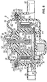
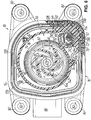
- An electronically commutated electric motor 26 is accommodated in the housing 16 (see FIG Fig. 3 and 5 ), the one essentially cup-shaped, magnetic rotor 28 rotatable about an axis of rotation A, which has a plurality of curved blade extensions 30 on the end face (cf. in particular Fig. 6 ) is provided as a means for conveying liquid, comprises a stator 34 having a motor winding 32 and a magnetic field sensor 36 required in a manner known per se for electronic commutation for detecting the rotational angle position of the rotor 28 (see FIG Fig. 3 ).
- the housing 16 is constructed in several parts, more precisely in three parts, with an upper pump housing section 38, which has the liquid inlet 18 and the liquid outlet 20, a central stator housing section 40, which carries the annular stator 34, so that it supports the rotor 28 in relation to the axis of rotation A.
- stator housing section 40 extends, as seen along the axis of rotation A, into the rotor 28 with a housing shoulder 48 which is designed to accommodate the magnetic field sensor 36.
- a sealing element 50 is provided on the housing 16 which, in a triple function, simultaneously seals the pump outer flange surface 14 of the housing 16 from the gear housing 12, separates the liquid space 42 from the electronics space 46 and the electronics space 46 seals off from the environment.
- the pump housing section 38 designed as a plastic part made from a laser-transparent, glass fiber reinforced polyphthalamide (PPA 35 GF) are in particular the Fig. 3 , 5 and 6th refer to.
- the pump housing section 38 has a pump housing flange 52 radially on the outside, on which the pump-external flange surface 14 and a pump-internal flange surface 54 are formed on opposite sides.
- the sealing element 50 which is made of an elastomeric material, is fastened to the pump housing flange 52 of the pump housing section 38 in a manner to be described below.
- the pump housing section 38 Radially inside the pump housing flange 52, the pump housing section 38 is raised like a dome and delimits, partly together with the rotor 28 and the stator housing section 40, in the area of the liquid space 42 a pump channel 56, which can essentially be divided into four areas, namely - from radially inside seen radially outward - (1.) a central, ie, centered with respect to the axis of rotation A, essentially funnel-shaped input region 58 (see in particular Fig. 5 ), (2) has a central, substantially annular accelerating region 60, in which the blade projections 30 move in the operation of the liquid pump 10 of the rotor 28, and (3) a substantially helical conveying portion 62 (see also Figs.
- the liquid In the funnel-shaped inlet area 58, the liquid then experiences a flow deflection by 90 ° (from radially in the direction of the axis of rotation A to axially along the axis of rotation A) until it hits the rotor 28 with its blade extensions 30, where a further flow deflection by about 90 ° takes place ( from axially along the axis of rotation A to radially away from the axis of rotation A).
- the middle acceleration range 60 of the pump channel 56 which in section ( Fig.
- the liquid is then conveyed essentially in the circumferential direction to the tubular outlet region 64.
- the flow of the liquid is again deflected by approx.
- the pump housing section 38 also has a bearing extension 68 at a central point, ie adjacent to the input area 58, for the support of the rotor 28, which will be described later that the pump housing flange 52 is provided radially outside the pump inner flange surface 54 and adjoining it with a circumferential groove 70 for receiving a circumferential collar 72 on the motor housing section 44, which is essentially complementary when viewed in a plan view.
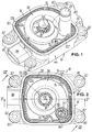
- the pump housing section 38 according to FIGS Fig. 1, 2 and 6th with 74 shots (in Fig. 6 bottom center with pass hole and top right with elongated hole) for positioning pins 76 molded onto stator housing section 40 (see again Fig. 6 ), which serve to align the stator housing section 40 with respect to the pump housing section 38.
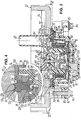
- the motor housing section 44 which is also injection-molded as a plastic part made of a glass fiber reinforced polyphthalamide (PPA 50 GF), is laser-welded to the pump housing section 38 - indirectly suitably aligned via the stator housing section 40 - with its collar 72 all around in the groove 70 of the pump housing flange 52 (in Fig. 4 indicated by the cross hatching at the bottom of the groove 70). This is based on the Fig. 4 and 5 the pump housing section 38 abuts the pump-inner flange surface 54 of the pump housing flange 52 on a circumferential shoulder 78 of the motor housing section 44 that adjoins the collar 72 in a radially inward direction.
- PPA 50 GF glass fiber reinforced polyphthalamide
- the motor housing section 44 has four fastening eyes 80 radially on the outside, each of which is lined with a metal sleeve 82 overmolded in a form-fitting manner.
- the sleeves 82 in the assembled state of the liquid pump 10 are penetrated by head screws 84, which are screwed into the respective assigned threaded bores 86 distributed around the opening 22 in the gear housing 12 in order to fasten the liquid pump 10 from the outside on the gear housing 12 and thereby also to connect the individual parts of the housing 16 firmly to one another.
- the above-mentioned welded connection between pump housing section 38 and motor housing section 44 serves primarily as a transport lock.
- the motor housing section 44 is provided with a plug collar 88 for an electrical connection of the liquid pump 10.
- electrical conductors 90 are embedded or injected into the motor housing section 44, which lead from the area of the connector collar 88 into the electronics compartment 46.
- the cuts according to the Fig. 4 and 5 also show that an electronic circuit board 92 with known electronic components required for pump control is integrated in the electronics compartment 46 of the housing 16.
- the electronics board 92 itself is press-fit, one of which is shown in FIG Fig.
- a connection is shown at 94, makes contact with the electrical conductors 90 in the motor housing section 44 and is supported on projections 96 formed on the inside of the motor housing section 44, to which the electronic circuit board 92 is also partially fastened by means of screws 98.
- the stator housing section 40 Analogously to the positioning pins 76 for the pump housing section 38, the stator housing section 40 also extends into the Fig. 3 and 5 below positioning pins (not shown here) which engage in assigned holes (fitting hole and elongated hole; not shown in the figures) in the motor housing section 44 and extend through corresponding holes (not shown) in the electronic circuit board 92.
- the electrical parts of the liquid pump 10 are also contacted via press-fit connections 94 to the electronic circuit board 92; of this is only in Fig.
- the press-fit connection 94 to a further electrical conductor 90 which is embedded or injected in the stator housing section 40 and to which a temperature sensor 100 is connected is shown.
- Corresponding electrical connections exist to the motor winding 32 and to the magnetic field sensor 36.
- the stator housing section 40 is also injection molded as a plastic part from a glass fiber reinforced polyphthalamide (PPA 50 GF).
- PPA 50 GF glass fiber reinforced polyphthalamide
- both said electrical conductors 90 and pole plates 102 of stator 34 are embedded by overmolding with the plastic material of stator housing section 40.
- the stator 34 is completed by a slotted (not shown), metallic return ring 104, which is pulled onto radially outwardly protruding edges of the pole sheets 102 in a force-locking manner and also crimped with the edges of the pole sheets 102 (not visible in the figures).
- stator housing section 40 carrying the stator 34 surrounds the central housing section 48 of the stator housing section 40 in a coaxial positional relationship with respect to the axis of rotation A, leaving an annular space 106 into which the rotor 28 is immersed.
- FIG Fig. 3 At a radially outer point of the housing shoulder 48, ie at a radial distance from the axis of rotation A, this is according to FIG Fig. 3 with a recess 108, which is open towards the motor housing section 44, for receiving the magnetic field sensor 36 - which can be a Hall element, for example.
- a further bearing extension 110 for mounting the rotor 28 is also provided in the center of the essentially cup-shaped housing section 48 of the stator housing section 40 on the side facing away from the pump housing section 38 in the illustrated embodiment.
- the recess 108 for receiving the magnetic field sensor 36 and the bearing point formed by the bearing extension 110 within the rotor 28 are spaced apart but next to one another in a plane which runs transversely to the axis of rotation A. This “radial juxtaposition” of said functional elements is also beneficial for the flat design of the liquid pump 10.
- the magnetic field sensor 36 is arranged near the outer wall of the rotor 28, which is conducive to a good quality of the detected signal due to the maximum distance from the axis of rotation A on the one hand and the proximity to the rotor 28 on the other.
- a partial area 112 of the stator housing section 40 protrudes in the radial direction adjacent to the stator 34 and axially in the direction of the pump housing section 38 in a ramp-like manner over the remaining stator housing section 40 and thus forms a "soft" transition between the helical conveying area 62 and the tubular outlet area 64 of the pump channel 56.
- This sub-area 112 of the stator housing section 40 is according to FIGS Fig. 3 and 6th provided with a receiving recess 114, which is open towards the motor housing section 44, for the temperature sensor 100, so that the latter is integrated near the liquid outlet 20 in the housing 16 of the liquid pump 10.
- stator housing section 40 Radially on the outside, the stator housing section 40 finally has a stator housing flange 116, which is clamped in a sandwich-like manner between the pump housing section 38 and the motor housing section 44 and which radially centers the stator housing section 40 in an associated shoulder 118 on the motor housing section 44 with respect to the axis of rotation A.
- the pump housing flange 52 of the pump housing section 38 starting from the pump outer flange surface 14 of the housing 16, is provided with a circumferential recess or groove 120 for receiving a first sealing section 122 of the sealing element 50, which has two sealing lips 124, 126, ie a radially inner sealing lip 124 and a radially outer sealing lip 126 protrudes beyond the pump-outer flange surface 14 in order to seal with respect to the transmission housing 12.
- the pump housing flange 52 is provided with a further circumferential recess or groove 128 for receiving a second sealing section 130 of the sealing element 50.
- the latter protrudes with two sealing lips 132, 134 over the pump inner flange surface 54, of which one, radially inner sealing lip 132 interacts with the stator housing flange 116 of the stator housing section 40 in order to separate the liquid space 42 from the electronics space 46.
- the other, radially outer sealing lip 134 interacts with an assigned shoulder 136 of the motor housing section 44 in order to seal off the electronics compartment 46 from the environment.
- the second sealing section 130 of the sealing element 50 overlaps or covers the centering area between the stator housing flange 116 of the stator housing section 40 and the shoulder 118 on the motor housing section 44 in the radial direction with respect to the axis of rotation A of the rotor 28, with the deformation of the sealing lips 132, 134 also a defined prestressing force is generated between the individual parts of the housing 16.
- the sealing element 50 is molded onto the pump housing flange 52 of the pump housing section 38 in a form-fitting manner.
- a plurality of openings 138 which are preferably evenly spaced in the circumferential direction, i.e. viewed along the grooves 120, 128, are formed in the pump housing flange 52, which openings the grooves 120 , 128 connect and are injected with the elastomeric material of the sealing element 50 in order to materially connect the first sealing section 122 and the second sealing section 130 of the sealing element 50 to one another.
- the rotor 28 has a permanent magnetic outer cylinder section 140 which cooperates in a known manner with the motor winding 32 of the stator 34 and a bottom section 142 designed as an impeller on the side facing away from the housing section 48 of the stator housing section 40 with the blade extensions 30 and consists of a plastic-bonded magnetic material, which is sprayed directly onto a metallic (preferably steel) rotor shaft 144 rotatably mounted in the housing 16 while also shaping the blade extensions 30.
- the rotor shaft 144 is radially directly on both sides of the bottom section 142, ie without bearing bushes or the like.
- a thrust washer 150 surrounding the rotor shaft 144 can be provided between the bottom section 142 of the rotor 28 and the bearing extension 68, via which the rotor 28 is supported axially on the bearing extension 68 during operation of the liquid pump 10 when the rotor 28 is set on it due to the Pressure ratios is raised against gravity.
- the liquid pump 10 according to the second exemplary embodiment will now be described with reference to FIG Fig. 7 are described only to the extent that they differ materially from the above with reference to the Figures 1 to 6 the first embodiment described in detail differs.
- the same reference symbols denote components or groups of the second exemplary embodiment which are the same or correspond to those of the first exemplary embodiment.
- the housing section 48 is not essentially cup-shaped, but has two sections integrally formed on the stator housing section 40 via a circular base 151 seen in a plan view in the direction of the axis of rotation A, with which the housing shoulder 48 - again viewed along the axis of rotation A - extends into the rotor 28, namely a central bearing section 152 and a sensor section 154, which is spaced radially from the bearing section 152 with respect to the axis of rotation A, in the vicinity of the cylinder section 140 of the rotor 28.
- the bearing section 152 is open towards the rotor 28 and is provided at the axial height of the sensor section 154 with the cylindrical recess 146 for the direct, radial bearing of the rotor shaft 144.
- the rotor shaft 144 does not extend to the base or floor of the cylindrical recess 146 in the bearing section 152, but ends beforehand at an axial distance therefrom.
- the bearing section 152 is made longer than the bearing extension 110 in the first embodiment and, viewed in the direction of the axis of rotation A, ends just before the bottom section 142 of the rotor 28.
- the rotor shaft 144 is inserted thrust washer 158, via which the rotor 28 can be axially supported on the bearing section 152.
- the sensor section 154 is provided with the recess 108, which is open towards the electronics compartment 46 or the electronics circuit board 92, for receiving the magnetic field sensor 36 and extends only up to half the height of the cylinder section 140 of the rotor 28 and the radial bearing point for the rotor shaft 144 on the side of the stator housing section 40 is arranged in a very compact design in a plane in the rotor 28 which extends transversely or perpendicular to the axis of rotation A.
- a liquid pump driven by an electric motor which can be used for the forced lubrication of a gearbox for motor vehicles, has a housing having a liquid inlet and a liquid outlet and an electronically commutated electric motor accommodated therein.
- the latter comprises an essentially cup-shaped, magnetic rotor rotatable about an axis of rotation with means for conveying liquid, an annular stator with a motor winding which, in a coaxial arrangement with respect to the axis of rotation, at least partially surrounds the rotor along the axis of rotation, as well as a magnetic field sensor for detecting the position of the Rotor.
- the housing here has a stator housing section which carries the stator, separates it from a liquid space in which the rotor is arranged, and, viewed along the axis of rotation, extends into the rotor with a housing shoulder which is designed to accommodate the magnetic field sensor, see above that the liquid pump overall has only a low overall height.
Landscapes
- Engineering & Computer Science (AREA)
- Mechanical Engineering (AREA)
- General Engineering & Computer Science (AREA)
- Power Engineering (AREA)
- Microelectronics & Electronic Packaging (AREA)
- Structures Of Non-Positive Displacement Pumps (AREA)
- Connection Of Motors, Electrical Generators, Mechanical Devices, And The Like (AREA)
- Details And Applications Of Rotary Liquid Pumps (AREA)
- General Details Of Gearings (AREA)
Claims (14)
- Pompe à liquides (10) entrainée par moteur électrique, notamment destinée à la lubrification forcée d'une boite de vitesses pour véhicules automobiles, comprenant un carter (16), qui possède une entrée de liquide (18) et une sortie de liquide (20), et dans lequel est reçu un moteur électrique (26) à commutation électronique, qui possède un rotor magnétique (28) avec des moyens (30) pour refouler le liquide, sensiblement en forme de pot et rotatif autour d'un axe de rotation (A), un stator (34) de forme annulaire et présentant un enroulement de moteur (32), qui, relativement à un agencement coaxial à l'axe de rotation (A), entoure au moins partiellement le rotor (28) vu le long de l'axe de rotation (A), ainsi qu'un capteur de champ magnétique (36) pour la reconnaissance de position du rotor (28), pompe dans laquelle le carter (16) présente une partie de carter de stator (40), qui porte le stator (34), sépare celui-ci d'une chambre à liquide (42) dans laquelle est agencé le rotor (28), et qui, vu le long de l'axe de rotation (A), s'étend avec un épaulement de carter (48) à l'intérieur du rotor (28), caractérisée en ce que l'épaulement de carter (48) de la partie de carter de stator (40), qui, vu le long de l'axe de rotation (A), s'étend à l'intérieur du rotor (28), est conçu pour accueillir le capteur de champ magnétique (36) et en ce que dans le carter (16) est intégrée une platine d'électronique (92) à laquelle sont connectées les parties électriques de la pompe à liquides (10), par l'intermédiaire de connexions par emmanchement de broches ou par soudage ou par brasage.
- Pompe à liquides (10) selon la revendication 1, caractérisée en ce que le carter (16) peut être bridé sur un réservoir de liquide (12) par l'intermédiaire d'une surface de bridage (14) extérieure de la pompe, et qui, en étant d'une configuration en plusieurs parties, possède en-dehors de la partie de carter de stator (40), une partie de carter de pompe (38), qui présente l'entrée de liquide (18) et la sortie de liquide (20), et délimite, en commun avec la partie de carter de stator (40), la chambre de liquide (42), et une partie de carter de moteur (44), qui délimite, en commun avec la partie de carter de stator (40), une chambre d'électronique (46) dans laquelle se trouve au moins le stator (34).
- Pompe à liquides (10) selon la revendication 2, caractérisée en ce que la partie de carter de pompe (38) et la partie de carter de moteur (44) sont réalisées sous forme de pièces en matière plastique, et sont soudées l'une à l'autre.
- Pompe à liquide (10) selon la revendication 2 ou la revendication 3, caractérisée en ce que la partie de carter de stator (40) présente une bride de carter de stator (116), qui est enserrée entre la partie de carter de pompe (38) et la partie de carter de moteur (44), et assure le centrage de la partie de carter de stator (40) sur la partie de carter de moteur (44) relativement à l'axe de rotation (A).
- Pompe à liquides (10) selon l'une des revendications 2 à 4, caractérisée en ce qu'il est prévu un élément d'étanchéité (50), qui, simultanément, assure l'étanchéité sur la surface de bridage (14) extérieure de la pompe, du carter (16), par rapport au réservoir de liquide (12), sépare la chambre de liquide (42) de la chambre d'électronique (46), et assure l'étanchéité de la chambre d'électronique (46) par rapport à l'environnement.
- Pompe à liquides (10) selon la revendication 5, caractérisée en ce que la surface de bridage (14) extérieure de la pompe, du carter (16), est munie d'une rainure périphérique (120) destinée à accueillir un premier tronçon d'étanchéité (122) de l'élément d'étanchéité (50), qui fait saillie, avec deux lèvres d'étanchéité (124, 126), de la surface de bridage (14) extérieure de la pompe, en vue d'assurer l'étanchéité par rapport au réservoir de liquide (12).
- Pompe à liquides (10) selon la revendication 5 ou la revendication 6, caractérisée en ce que la partie de carter de pompe (38) présente une bride de carter de pompe (52) sur laquelle sont formées, sur des cotes opposés, la surface de bridage (14) extérieure de la pompe et une surface de bridage (54) intérieure de la pompe, qui est munie d'une rainure périphérique (128) destinée à accueillir un deuxième tronçon d'étanchéité (130) de l'élément d'étanchéité (50), qui fait saillie, avec deux lèvres d'étanchéité (132, 134), de la surface de bridage (54) intérieure de la pompe, et dont une lèvre d'étanchéité (132) interagit avec la partie de carter de stator (40) pour séparer la chambre de liquide (42) de la chambre d'électronique (46), tandis que l'autre lèvre d'étanchéité (134) interagit avec la partie de carter de moteur (44) en vue d'assurer l'étanchéité de la chambre d'électronique (46) par rapport à l'environnement.
- Pompe à liquides (10) selon l'une des revendications 5 à 7, caractérisée en ce que l'élément d'étanchéité (50) réalisé en un matériau élastomère, est fixé à la partie de carter de pompe (38), à savoir notamment par complémentarité de formes, en étant moulé par injection sur la partie de carter de pompe (38).
- Pompe à liquides (10) selon l'une des revendications 6 à 8, caractérisée en ce qu'entre la rainure périphérique (120) sur la surface de bridage (14) extérieure de la pompe et la rainure périphérique (128) sur la surface de bridage (54) intérieure de la pompe, sont prévues une pluralité d'ouvertures (138) qui sont espacées les unes des autres dans la direction périphérique, et sont traversées par le matériau élastomère injecté de l'élément d'étanchéité (50), en vue de relier mutuellement le premier tronçon d'étanchéité (122) et le deuxième tronçon d'étanchéité (130) de l'élément d'étanchéité (50).
- Pompe à liquides (10) selon l'une des revendications précédentes, caractérisée en ce que des tôles polaires (102) du stator (34) sont noyées dans la partie de carter de stator (40) réalisée en une matière plastique, en étant surmoulées par injection de matière plastique.
- Pompe à liquides (10) selon l'une des revendications précédentes, caractérisée en ce que dans le carter (16) est intégré un capteur de température (100), de préférence à proximité de la sortie de liquide (20), en étant de préférence reçu dans un évidement d'accueil (114) dans la partie de carter de stator (40).
- Pompe à liquides (10) selon l'une des revendications précédentes, caractérisée en ce que l'entrée de liquide (18) du carter (16) est orientée transversalement à l'axe de rotation (A) du rotor (28).
- Pompe à liquides (10) selon l'une des revendications précédentes, caractérisée en ce que le rotor (28) possède un tronçon cylindrique extérieur (140) à aimantation permanente interagissant avec l'enroulement de moteur (32), ainsi qu'un tronçon de fond (142), qui est réalisé sous forme de roue à ailettes sur le cote oppose à celui dirigé vers l'épaulement de carter (48) de la partie de carter de stator (40), le rotor étant réalisé en un matériau magnétique a liant synthétique et étant directement moulé par injection sur un arbre de rotor (144) monté rotatif dans le carter (16).
- Pompe à liquides (10) selon la revendication 13, caractérisée en ce que l'arbre de rotor (144) est monté, de part et d'autre du tronçon de fond (142), directement dans le carter (16), au moins de manière radiale, à savoir, d'un côté dans l'épaulement de carter (48) de la partie de carter de stator (40), et de l'autre côté dans un embout de palier (68) de la partie de carter de pompe (38).
Priority Applications (1)
| Application Number | Priority Date | Filing Date | Title |
|---|---|---|---|
| PL14776581T PL3087277T3 (pl) | 2013-11-29 | 2014-09-22 | Napędzana silnikiem elektrycznym pompa cieczy, zwłaszcza dla wymuszonego smarowania skrzyni biegów dla pojazdów mechanicznych |
Applications Claiming Priority (2)
| Application Number | Priority Date | Filing Date | Title |
|---|---|---|---|
| DE102013017975.0A DE102013017975A1 (de) | 2013-11-29 | 2013-11-29 | Elektromotorisch angetriebene Flüssigkeitspumpe, insbesondere zur Zwangsschmierung eines Schaltgetriebes für Kraftfahrzeuge |
| PCT/EP2014/002563 WO2015078540A1 (fr) | 2013-11-29 | 2014-09-22 | Pompe à liquide entraînée par un moteur électrique en particulier pour la lubrification forcée d'une boîte de vitesses de véhicules automobiles |
Publications (3)
| Publication Number | Publication Date |
|---|---|
| EP3087277A1 EP3087277A1 (fr) | 2016-11-02 |
| EP3087277B1 EP3087277B1 (fr) | 2018-04-18 |
| EP3087277B2 true EP3087277B2 (fr) | 2021-10-27 |
Family
ID=51625994
Family Applications (1)
| Application Number | Title | Priority Date | Filing Date |
|---|---|---|---|
| EP14776581.2A Active EP3087277B2 (fr) | 2013-11-29 | 2014-09-22 | Pompe à liquide entraînée par un moteur électrique en particulier pour la lubrification forcée d'une boîte de vitesses de véhicules automobiles |
Country Status (12)
| Country | Link |
|---|---|
| US (1) | US10451073B2 (fr) |
| EP (1) | EP3087277B2 (fr) |
| JP (1) | JP6707450B2 (fr) |
| KR (1) | KR101902665B1 (fr) |
| CN (1) | CN106415017B (fr) |
| BR (1) | BR112016012130B1 (fr) |
| DE (1) | DE102013017975A1 (fr) |
| ES (1) | ES2673585T3 (fr) |
| MX (1) | MX375708B (fr) |
| PL (1) | PL3087277T3 (fr) |
| TR (1) | TR201807139T4 (fr) |
| WO (1) | WO2015078540A1 (fr) |
Cited By (2)
| Publication number | Priority date | Publication date | Assignee | Title |
|---|---|---|---|---|
| DE102022207129A1 (de) * | 2022-07-12 | 2024-01-18 | Brose Fahrzeugteile SE & Co. Kommanditgesellschaft, Würzburg | Elektrische Fluidpumpe für ein Kraftfahrzeug |
| DE102022124164A1 (de) * | 2022-09-21 | 2024-03-21 | Minebea Mitsumi Inc. | Flüssigkeitspumpenantriebsvorrichtung |
Families Citing this family (34)
| Publication number | Priority date | Publication date | Assignee | Title |
|---|---|---|---|---|
| GB2518208B (en) | 2013-09-13 | 2016-06-01 | Yasa Motors Ltd | Stator-plate Overmoulding |
| GB2518209B (en) * | 2013-09-13 | 2016-08-03 | Yasa Motors Ltd | Pole-piece Bonding |
| US10256758B2 (en) * | 2014-11-26 | 2019-04-09 | Kohler Co. | Printed circuit board based exciter |
| EP3136553B1 (fr) * | 2015-08-26 | 2017-10-11 | Lakeview Innovation Ltd. | Systeme de stator enrobe de plastique par extrusion dote d'une dissipation de chaleur amelioree et son procede de fabrication |
| DE202015105246U1 (de) * | 2015-10-05 | 2017-01-09 | Ebm-Papst St. Georgen Gmbh & Co. Kg | Elektromotor mit einer Steuerelektronik |
| DE102016206397A1 (de) * | 2016-04-15 | 2017-10-19 | Bühler Motor GmbH | Elektronisch kommutierter Gleichstrommotor mit Einzelpolen |
| DE102016206953A1 (de) * | 2016-04-25 | 2017-10-26 | Mahle International Gmbh | Stellvorrichtung |
| FR3060671B1 (fr) * | 2016-12-16 | 2021-01-22 | Wilo Intec | Pompe de circulation d'un fluide |
| DE102017213412B4 (de) * | 2017-08-02 | 2019-04-04 | Zf Friedrichshafen Ag | Ölpumpenantriebsvorrichtung |
| DE102017214309A1 (de) | 2017-08-17 | 2019-02-21 | Continental Automotive Gmbh | Rotor für eine elektrische Maschine, insbesondere eines Kraftfahrzeugs, sowie Verfahren zum Herstellen eines solchen Rotors |
| CN107546440A (zh) * | 2017-09-25 | 2018-01-05 | 青岛金立磁性材料有限公司 | 一种用于电动大巴电池组冷却的塑磁转子组 |
| US20190285163A1 (en) * | 2018-03-15 | 2019-09-19 | GM Global Technology Operations LLC | Vehicle propulsion system |
| DE102018208716A1 (de) * | 2018-06-04 | 2019-12-05 | Magna Powertrain Bad Homburg GmbH | Elektrischer Aktuator |
| DE102018208853A1 (de) * | 2018-06-05 | 2019-12-05 | Magna Powertrain Bad Homburg GmbH | Pumpe |
| FR3086125B1 (fr) * | 2018-09-14 | 2020-10-02 | Valeo Equip Electr Moteur | Machine electrique tournante munie d'un palier realise a partir de deux parties surmoulees |
| DE102018128178A1 (de) * | 2018-11-12 | 2020-05-14 | Schaeffler Technologies AG & Co. KG | Elektrische Maschine mit integriertem Temperatursensor und Rotorzustandserfassungssensor |
| DE102019213522A1 (de) * | 2019-09-05 | 2021-03-11 | Mahle International Gmbh | Getriebeölmodul für eine Getriebeeinrichtung |
| CN112524048A (zh) * | 2019-09-18 | 2021-03-19 | 广东德昌电机有限公司 | 液体泵 |
| DE102019130723A1 (de) | 2019-11-14 | 2021-05-20 | Fte Automotive Gmbh | Flüssigkeitspumpe |
| IT201900021642A1 (it) * | 2019-11-19 | 2021-05-19 | Sicce S R L | Pompa fluidodinamica |
| US12132373B2 (en) | 2020-01-15 | 2024-10-29 | East West Manufacturing, Llc | Electronically commutated DC motor with encapsulating controller |
| WO2021146130A1 (fr) | 2020-01-15 | 2021-07-22 | East West Manufacturing, Llc | Moteur cc à commutation électronique |
| DE102020106849A1 (de) | 2020-03-12 | 2021-09-16 | Fte Automotive Gmbh | Flüssigkeitspumpe, insbesondere zur Versorgung eines Getriebes eines Elektro- oder Hybridantriebsmoduls eines Kraftfahrzeugs |
| DE102020203459A1 (de) | 2020-03-18 | 2021-09-23 | Mahle International Gmbh | Getriebeölfiltermodul |
| DE102020113551A1 (de) | 2020-05-19 | 2021-11-25 | Fte Automotive Gmbh | Antriebsaggregat |
| CN116261822B (zh) * | 2020-10-16 | 2026-03-13 | 松下知识产权经营株式会社 | 模制马达 |
| DE102021102395A1 (de) * | 2021-02-02 | 2022-08-04 | Fte Automotive Gmbh | Flüssigkeitspumpe und Verfahren zur Montage einer Flüssigkeitspumpe |
| CN113250950A (zh) * | 2021-05-24 | 2021-08-13 | 中国能源建设集团山西省电力勘测设计院有限公司 | 一种湿转子内啮合直驱齿轮油泵及其装配方法 |
| CN113944531B (zh) * | 2021-09-02 | 2023-03-03 | 东风汽车集团股份有限公司 | 一种发动机润滑油路控制方法 |
| DE102021210043A1 (de) * | 2021-09-10 | 2023-03-16 | Vitesco Technologies Germany Gmbh | Pumpe, insbesondere Getriebeölpumpe mit modularem Aufbau |
| CN216278663U (zh) * | 2021-10-20 | 2022-04-12 | 凡成(厦门)智能制造股份有限公司 | 一种液体供应组件及液体供应设备 |
| DE102021130216A1 (de) | 2021-11-18 | 2023-05-25 | Schwäbische Hüttenwerke Automotive GmbH | Pumpe-Motor-Einheit mit zentriertem Stator |
| DE102021133692A1 (de) * | 2021-12-17 | 2023-06-22 | Pierburg Pump Technology Gmbh | Elektrische Kraftfahrzeug-Fluidpumpe |
| CN120576107A (zh) * | 2025-08-01 | 2025-09-02 | 四川芯智热控技术有限公司 | 一种具有轴向磁通结构的电子水泵 |
Citations (4)
| Publication number | Priority date | Publication date | Assignee | Title |
|---|---|---|---|---|
| JP2005188296A (ja) † | 2003-12-24 | 2005-07-14 | Matsushita Electric Ind Co Ltd | Dcブラシレスポンプ |
| JP2005344589A (ja) † | 2004-06-02 | 2005-12-15 | Asmo Co Ltd | キャンドモータポンプ |
| WO2007023014A1 (fr) † | 2005-08-22 | 2007-03-01 | Robert Bosch Gmbh | Pompe centrifuge |
| EP2587066A2 (fr) † | 2011-10-26 | 2013-05-01 | Assoma Inc. | Pompe motorisée à aimant permanent |
Family Cites Families (20)
| Publication number | Priority date | Publication date | Assignee | Title |
|---|---|---|---|---|
| YU177488A (en) | 1987-11-17 | 1990-12-31 | Zahnradfabrik Friedrichshafen | Placing of a pump in an transporter |
| DE29709007U1 (de) * | 1997-05-22 | 1997-07-24 | Lieu, Chen-Ta, Feng Yuan, Taichung | Magnetisch kuppelbare Pumpe |
| JPH11153098A (ja) | 1997-09-19 | 1999-06-08 | Nikkiso Co Ltd | キャンドモータポンプ用凍結防止装置 |
| JP2000145683A (ja) | 1998-11-10 | 2000-05-26 | Mitsubishi Electric Corp | ポンプ装置 |
| DE19934382A1 (de) * | 1999-07-22 | 2001-02-01 | Bosch Gmbh Robert | Flüssigkeitspumpe |
| DE19956380C1 (de) * | 1999-11-24 | 2001-01-04 | Bosch Gmbh Robert | Flüssigkeitspumpe mit einem Motorgehäuse und Verfahren zur Herstellung eines Motorgehäuses |
| DE10045597C1 (de) * | 2000-09-15 | 2002-01-31 | Buhler Motor Gmbh | Pumpe mit einem elektronisch kommutierten Gleichstrommotor |
| DE10052797A1 (de) * | 2000-10-25 | 2002-05-08 | Bosch Gmbh Robert | Elektromotorisch angetriebene Pumpe und Verfahren zur Herstellung einer solchen Pumpe |
| US6864653B2 (en) * | 2001-11-26 | 2005-03-08 | Ebm-Papst St. Georgen Gmbh & Co. Kg | Equipment fan |
| DE102005005154A1 (de) | 2005-02-04 | 2006-08-10 | Bayerische Motoren Werke Ag | Fahrzeug mit einem Getriebe |
| DE102006012838A1 (de) | 2005-05-11 | 2006-11-23 | Zf Friedrichshafen Ag | Automatgetriebe eines Kraftfahrzeuges |
| JP2007318987A (ja) * | 2006-04-28 | 2007-12-06 | Nippon Densan Corp | 磁気センサを有するモータおよびポンプ、および、ステータの製造方法、並びに、モータおよびポンプの製造方法 |
| DE102006021242B4 (de) | 2006-04-28 | 2012-06-21 | Bühler Motor GmbH | Elektromotor |
| US20070252487A1 (en) | 2006-04-28 | 2007-11-01 | Nidec Corporation | Motor and pump having magnetic sensor, connecting method between circuit board having magnetic sensor and stator, and manufacturing method of motor and pump |
| DE102006058955B4 (de) * | 2006-12-12 | 2014-07-24 | DüRR DENTAL AG | Saugvorrichtung für dentale, medizinische und industrielle Zwecke |
| DE102007018504B4 (de) | 2007-04-19 | 2016-11-17 | Zf Friedrichshafen Ag | Kühl- und Schmiermittelversorgungssystem eines Getriebes |
| EP2031737A1 (fr) | 2007-08-30 | 2009-03-04 | Alcatel Lucent | Moteur électrique sans balai et pompe électrique |
| JP2009074433A (ja) * | 2007-09-20 | 2009-04-09 | Panasonic Electric Works Co Ltd | ポンプ |
| JP2011052569A (ja) | 2009-08-31 | 2011-03-17 | Yamada Seisakusho Co Ltd | ウォータポンプ及びその組付方法 |
| DE102009049904A1 (de) * | 2009-10-12 | 2011-04-14 | Deutsche Vortex Gmbh & Co. Kg | Trennwand für einen Elektromotor und Pumpe mit Elektromotor |
-
2013
- 2013-11-29 DE DE102013017975.0A patent/DE102013017975A1/de not_active Withdrawn
-
2014
- 2014-09-22 ES ES14776581.2T patent/ES2673585T3/es active Active
- 2014-09-22 JP JP2016534911A patent/JP6707450B2/ja active Active
- 2014-09-22 EP EP14776581.2A patent/EP3087277B2/fr active Active
- 2014-09-22 US US15/039,908 patent/US10451073B2/en active Active
- 2014-09-22 KR KR1020167017371A patent/KR101902665B1/ko active Active
- 2014-09-22 PL PL14776581T patent/PL3087277T3/pl unknown
- 2014-09-22 TR TR2018/07139T patent/TR201807139T4/tr unknown
- 2014-09-22 MX MX2016006926A patent/MX375708B/es active IP Right Grant
- 2014-09-22 WO PCT/EP2014/002563 patent/WO2015078540A1/fr not_active Ceased
- 2014-09-22 CN CN201480074020.1A patent/CN106415017B/zh active Active
- 2014-09-22 BR BR112016012130-9A patent/BR112016012130B1/pt active IP Right Grant
Patent Citations (4)
| Publication number | Priority date | Publication date | Assignee | Title |
|---|---|---|---|---|
| JP2005188296A (ja) † | 2003-12-24 | 2005-07-14 | Matsushita Electric Ind Co Ltd | Dcブラシレスポンプ |
| JP2005344589A (ja) † | 2004-06-02 | 2005-12-15 | Asmo Co Ltd | キャンドモータポンプ |
| WO2007023014A1 (fr) † | 2005-08-22 | 2007-03-01 | Robert Bosch Gmbh | Pompe centrifuge |
| EP2587066A2 (fr) † | 2011-10-26 | 2013-05-01 | Assoma Inc. | Pompe motorisée à aimant permanent |
Cited By (2)
| Publication number | Priority date | Publication date | Assignee | Title |
|---|---|---|---|---|
| DE102022207129A1 (de) * | 2022-07-12 | 2024-01-18 | Brose Fahrzeugteile SE & Co. Kommanditgesellschaft, Würzburg | Elektrische Fluidpumpe für ein Kraftfahrzeug |
| DE102022124164A1 (de) * | 2022-09-21 | 2024-03-21 | Minebea Mitsumi Inc. | Flüssigkeitspumpenantriebsvorrichtung |
Also Published As
| Publication number | Publication date |
|---|---|
| DE102013017975A1 (de) | 2015-06-03 |
| MX375708B (es) | 2025-03-06 |
| CN106415017A (zh) | 2017-02-15 |
| JP2016540156A (ja) | 2016-12-22 |
| ES2673585T3 (es) | 2018-06-22 |
| TR201807139T4 (tr) | 2018-06-21 |
| US20160377082A1 (en) | 2016-12-29 |
| KR20160093044A (ko) | 2016-08-05 |
| KR101902665B1 (ko) | 2018-09-28 |
| BR112016012130A2 (pt) | 2017-08-08 |
| JP6707450B2 (ja) | 2020-06-10 |
| WO2015078540A1 (fr) | 2015-06-04 |
| US10451073B2 (en) | 2019-10-22 |
| EP3087277B1 (fr) | 2018-04-18 |
| BR112016012130B1 (pt) | 2021-12-28 |
| EP3087277A1 (fr) | 2016-11-02 |
| MX2016006926A (es) | 2016-12-15 |
| PL3087277T3 (pl) | 2018-08-31 |
| CN106415017B (zh) | 2019-09-20 |
Similar Documents
| Publication | Publication Date | Title |
|---|---|---|
| EP3087277B2 (fr) | Pompe à liquide entraînée par un moteur électrique en particulier pour la lubrification forcée d'une boîte de vitesses de véhicules automobiles | |
| EP3074632B1 (fr) | Pompe à liquides entraînée par un moteur électrique, en particulier pour la lubrification forcée de la boîte de vitesses de véhicules automobiles | |
| EP1725775B1 (fr) | Ensemble comprenant un moteur a induit exterieur a commutation electronique | |
| EP2500578B1 (fr) | Pompe de recirculation de chauffage | |
| DE2750801C2 (de) | Pumpe, insbesondere Faßpumpe | |
| EP2191138A1 (fr) | Rotor de pompe pour pompe à moteur à gaine | |
| EP2905472B1 (fr) | Pompe centrifuge de type humide | |
| EP1286055B1 (fr) | Pompe à rotor mouillé | |
| DE102020106849A1 (de) | Flüssigkeitspumpe, insbesondere zur Versorgung eines Getriebes eines Elektro- oder Hybridantriebsmoduls eines Kraftfahrzeugs | |
| EP4184761A1 (fr) | Unité pompe-moteur avec stator centré | |
| EP2696480A2 (fr) | Moteur à rotor extérieur commuté électroniquement | |
| EP3879105B1 (fr) | Insert de pompe et agencement de pompe doté d'un tel insert de pompe | |
| DE10315871A1 (de) | Bürstenloser Gleichstrommotor (BLDC-Motor) | |
| EP0814268B1 (fr) | Ensemble modulaire pour la fabrication d'une pompe, en particulier d'une pompe entraínée par une accouplement magnétique | |
| DE19959022C1 (de) | Antriebseinheit | |
| EP1310672A2 (fr) | Pompe à carburant pour un système d'alimentation de moteur à combustion interne et système d'alimentation | |
| DE102004047637B4 (de) | Elektrisch betriebene Pumpe mit Außenrotor | |
| EP3762607B1 (fr) | Dispositif de pompage pour un boîtier de système d'un véhicule | |
| DE2522165A1 (de) | Kreiselpumpe | |
| EP2990651B1 (fr) | Boîtier de pompe | |
| EP2045477B1 (fr) | Agencement de stockage destiné au stockage rotatif d'une partie de machine | |
| DE102004047635B4 (de) | Elektrisch betriebene Pumpe mit Innenrotor | |
| DE1950500U (de) | Pumpenaggregat. | |
| DE102011005304A1 (de) | Pumpe mit Elektromotor | |
| DE1703784A1 (de) | Hydraulikeinheit |
Legal Events
| Date | Code | Title | Description |
|---|---|---|---|
| PUAI | Public reference made under article 153(3) epc to a published international application that has entered the european phase |
Free format text: ORIGINAL CODE: 0009012 |
|
| 17P | Request for examination filed |
Effective date: 20160614 |
|
| AK | Designated contracting states |
Kind code of ref document: A1 Designated state(s): AL AT BE BG CH CY CZ DE DK EE ES FI FR GB GR HR HU IE IS IT LI LT LU LV MC MK MT NL NO PL PT RO RS SE SI SK SM TR |
|
| AX | Request for extension of the european patent |
Extension state: BA ME |
|
| DAX | Request for extension of the european patent (deleted) | ||
| GRAP | Despatch of communication of intention to grant a patent |
Free format text: ORIGINAL CODE: EPIDOSNIGR1 |
|
| STAA | Information on the status of an ep patent application or granted ep patent |
Free format text: STATUS: GRANT OF PATENT IS INTENDED |
|
| INTG | Intention to grant announced |
Effective date: 20171110 |
|
| GRAS | Grant fee paid |
Free format text: ORIGINAL CODE: EPIDOSNIGR3 |
|
| GRAA | (expected) grant |
Free format text: ORIGINAL CODE: 0009210 |
|
| STAA | Information on the status of an ep patent application or granted ep patent |
Free format text: STATUS: THE PATENT HAS BEEN GRANTED |
|
| AK | Designated contracting states |
Kind code of ref document: B1 Designated state(s): AL AT BE BG CH CY CZ DE DK EE ES FI FR GB GR HR HU IE IS IT LI LT LU LV MC MK MT NL NO PL PT RO RS SE SI SK SM TR |
|
| REG | Reference to a national code |
Ref country code: GB Ref legal event code: FG4D Free format text: NOT ENGLISH |
|
| REG | Reference to a national code |
Ref country code: CH Ref legal event code: EP |
|
| REG | Reference to a national code |
Ref country code: DE Ref legal event code: R096 Ref document number: 502014008020 Country of ref document: DE |
|
| REG | Reference to a national code |
Ref country code: AT Ref legal event code: REF Ref document number: 990799 Country of ref document: AT Kind code of ref document: T Effective date: 20180515 Ref country code: DE Ref legal event code: R082 Ref document number: 502014008020 Country of ref document: DE Representative=s name: OPPERMANN, MARK, DIPL.-ING., DE |
|
| REG | Reference to a national code |
Ref country code: IE Ref legal event code: FG4D Free format text: LANGUAGE OF EP DOCUMENT: GERMAN |
|
| REG | Reference to a national code |
Ref country code: ES Ref legal event code: FG2A Ref document number: 2673585 Country of ref document: ES Kind code of ref document: T3 Effective date: 20180622 |
|
| REG | Reference to a national code |
Ref country code: NL Ref legal event code: FP |
|
| REG | Reference to a national code |
Ref country code: SE Ref legal event code: TRGR |
|
| REG | Reference to a national code |
Ref country code: LT Ref legal event code: MG4D |
|
| REG | Reference to a national code |
Ref country code: FR Ref legal event code: PLFP Year of fee payment: 5 |
|
| REG | Reference to a national code |
Ref country code: SK Ref legal event code: T3 Ref document number: E 27579 Country of ref document: SK |
|
| PG25 | Lapsed in a contracting state [announced via postgrant information from national office to epo] |
Ref country code: AL Free format text: LAPSE BECAUSE OF FAILURE TO SUBMIT A TRANSLATION OF THE DESCRIPTION OR TO PAY THE FEE WITHIN THE PRESCRIBED TIME-LIMIT Effective date: 20180418 Ref country code: NO Free format text: LAPSE BECAUSE OF FAILURE TO SUBMIT A TRANSLATION OF THE DESCRIPTION OR TO PAY THE FEE WITHIN THE PRESCRIBED TIME-LIMIT Effective date: 20180718 Ref country code: FI Free format text: LAPSE BECAUSE OF FAILURE TO SUBMIT A TRANSLATION OF THE DESCRIPTION OR TO PAY THE FEE WITHIN THE PRESCRIBED TIME-LIMIT Effective date: 20180418 Ref country code: BG Free format text: LAPSE BECAUSE OF FAILURE TO SUBMIT A TRANSLATION OF THE DESCRIPTION OR TO PAY THE FEE WITHIN THE PRESCRIBED TIME-LIMIT Effective date: 20180718 Ref country code: LT Free format text: LAPSE BECAUSE OF FAILURE TO SUBMIT A TRANSLATION OF THE DESCRIPTION OR TO PAY THE FEE WITHIN THE PRESCRIBED TIME-LIMIT Effective date: 20180418 |
|
| PG25 | Lapsed in a contracting state [announced via postgrant information from national office to epo] |
Ref country code: HR Free format text: LAPSE BECAUSE OF FAILURE TO SUBMIT A TRANSLATION OF THE DESCRIPTION OR TO PAY THE FEE WITHIN THE PRESCRIBED TIME-LIMIT Effective date: 20180418 Ref country code: LV Free format text: LAPSE BECAUSE OF FAILURE TO SUBMIT A TRANSLATION OF THE DESCRIPTION OR TO PAY THE FEE WITHIN THE PRESCRIBED TIME-LIMIT Effective date: 20180418 Ref country code: RS Free format text: LAPSE BECAUSE OF FAILURE TO SUBMIT A TRANSLATION OF THE DESCRIPTION OR TO PAY THE FEE WITHIN THE PRESCRIBED TIME-LIMIT Effective date: 20180418 Ref country code: GR Free format text: LAPSE BECAUSE OF FAILURE TO SUBMIT A TRANSLATION OF THE DESCRIPTION OR TO PAY THE FEE WITHIN THE PRESCRIBED TIME-LIMIT Effective date: 20180719 |
|
| REG | Reference to a national code |
Ref country code: DE Ref legal event code: R026 Ref document number: 502014008020 Country of ref document: DE |
|
| PLBI | Opposition filed |
Free format text: ORIGINAL CODE: 0009260 |
|
| PG25 | Lapsed in a contracting state [announced via postgrant information from national office to epo] |
Ref country code: RO Free format text: LAPSE BECAUSE OF FAILURE TO SUBMIT A TRANSLATION OF THE DESCRIPTION OR TO PAY THE FEE WITHIN THE PRESCRIBED TIME-LIMIT Effective date: 20180418 Ref country code: DK Free format text: LAPSE BECAUSE OF FAILURE TO SUBMIT A TRANSLATION OF THE DESCRIPTION OR TO PAY THE FEE WITHIN THE PRESCRIBED TIME-LIMIT Effective date: 20180418 Ref country code: EE Free format text: LAPSE BECAUSE OF FAILURE TO SUBMIT A TRANSLATION OF THE DESCRIPTION OR TO PAY THE FEE WITHIN THE PRESCRIBED TIME-LIMIT Effective date: 20180418 |
|
| PLAX | Notice of opposition and request to file observation + time limit sent |
Free format text: ORIGINAL CODE: EPIDOSNOBS2 |
|
| PLAS | Information related to reply of patent proprietor to notice(s) of opposition deleted |
Free format text: ORIGINAL CODE: EPIDOSDOBS3 |
|
| PLBB | Reply of patent proprietor to notice(s) of opposition received |
Free format text: ORIGINAL CODE: EPIDOSNOBS3 |
|
| 26 | Opposition filed |
Opponent name: SCHWAEBISCHE HUETTENWERKE AUTOMOTIVE GMBH Effective date: 20190117 |
|
| PG25 | Lapsed in a contracting state [announced via postgrant information from national office to epo] |
Ref country code: SM Free format text: LAPSE BECAUSE OF FAILURE TO SUBMIT A TRANSLATION OF THE DESCRIPTION OR TO PAY THE FEE WITHIN THE PRESCRIBED TIME-LIMIT Effective date: 20180418 |
|
| PG25 | Lapsed in a contracting state [announced via postgrant information from national office to epo] |
Ref country code: MC Free format text: LAPSE BECAUSE OF FAILURE TO SUBMIT A TRANSLATION OF THE DESCRIPTION OR TO PAY THE FEE WITHIN THE PRESCRIBED TIME-LIMIT Effective date: 20180418 Ref country code: CZ Free format text: LAPSE BECAUSE OF NON-PAYMENT OF DUE FEES Effective date: 20180922 |
|
| REG | Reference to a national code |
Ref country code: CH Ref legal event code: PL Ref country code: SE Ref legal event code: EUG |
|
| GBPC | Gb: european patent ceased through non-payment of renewal fee |
Effective date: 20180922 |
|
| PLBB | Reply of patent proprietor to notice(s) of opposition received |
Free format text: ORIGINAL CODE: EPIDOSNOBS3 |
|
| PG25 | Lapsed in a contracting state [announced via postgrant information from national office to epo] |
Ref country code: SI Free format text: LAPSE BECAUSE OF FAILURE TO SUBMIT A TRANSLATION OF THE DESCRIPTION OR TO PAY THE FEE WITHIN THE PRESCRIBED TIME-LIMIT Effective date: 20180418 Ref country code: SE Free format text: LAPSE BECAUSE OF NON-PAYMENT OF DUE FEES Effective date: 20180923 |
|
| REG | Reference to a national code |
Ref country code: SK Ref legal event code: MM4A Ref document number: E 27579 Country of ref document: SK Effective date: 20180922 |
|
| REG | Reference to a national code |
Ref country code: BE Ref legal event code: MM Effective date: 20180930 |
|
| REG | Reference to a national code |
Ref country code: IE Ref legal event code: MM4A |
|
| PG25 | Lapsed in a contracting state [announced via postgrant information from national office to epo] |
Ref country code: LU Free format text: LAPSE BECAUSE OF NON-PAYMENT OF DUE FEES Effective date: 20180922 |
|
| PG25 | Lapsed in a contracting state [announced via postgrant information from national office to epo] |
Ref country code: IE Free format text: LAPSE BECAUSE OF NON-PAYMENT OF DUE FEES Effective date: 20180922 |
|
| PG25 | Lapsed in a contracting state [announced via postgrant information from national office to epo] |
Ref country code: SK Free format text: LAPSE BECAUSE OF NON-PAYMENT OF DUE FEES Effective date: 20180922 Ref country code: LI Free format text: LAPSE BECAUSE OF NON-PAYMENT OF DUE FEES Effective date: 20180930 Ref country code: CH Free format text: LAPSE BECAUSE OF NON-PAYMENT OF DUE FEES Effective date: 20180930 Ref country code: BE Free format text: LAPSE BECAUSE OF NON-PAYMENT OF DUE FEES Effective date: 20180930 |
|
| PG25 | Lapsed in a contracting state [announced via postgrant information from national office to epo] |
Ref country code: GB Free format text: LAPSE BECAUSE OF NON-PAYMENT OF DUE FEES Effective date: 20180922 |
|
| PG25 | Lapsed in a contracting state [announced via postgrant information from national office to epo] |
Ref country code: MT Free format text: LAPSE BECAUSE OF FAILURE TO SUBMIT A TRANSLATION OF THE DESCRIPTION OR TO PAY THE FEE WITHIN THE PRESCRIBED TIME-LIMIT Effective date: 20180418 |
|
| PG25 | Lapsed in a contracting state [announced via postgrant information from national office to epo] |
Ref country code: PL Free format text: LAPSE BECAUSE OF NON-PAYMENT OF DUE FEES Effective date: 20180922 |
|
| PG25 | Lapsed in a contracting state [announced via postgrant information from national office to epo] |
Ref country code: PT Free format text: LAPSE BECAUSE OF FAILURE TO SUBMIT A TRANSLATION OF THE DESCRIPTION OR TO PAY THE FEE WITHIN THE PRESCRIBED TIME-LIMIT Effective date: 20180418 |
|
| PG25 | Lapsed in a contracting state [announced via postgrant information from national office to epo] |
Ref country code: MK Free format text: LAPSE BECAUSE OF NON-PAYMENT OF DUE FEES Effective date: 20180418 Ref country code: CY Free format text: LAPSE BECAUSE OF FAILURE TO SUBMIT A TRANSLATION OF THE DESCRIPTION OR TO PAY THE FEE WITHIN THE PRESCRIBED TIME-LIMIT Effective date: 20180418 Ref country code: HU Free format text: LAPSE BECAUSE OF FAILURE TO SUBMIT A TRANSLATION OF THE DESCRIPTION OR TO PAY THE FEE WITHIN THE PRESCRIBED TIME-LIMIT; INVALID AB INITIO Effective date: 20140922 |
|
| PG25 | Lapsed in a contracting state [announced via postgrant information from national office to epo] |
Ref country code: IS Free format text: LAPSE BECAUSE OF FAILURE TO SUBMIT A TRANSLATION OF THE DESCRIPTION OR TO PAY THE FEE WITHIN THE PRESCRIBED TIME-LIMIT Effective date: 20180818 |
|
| REG | Reference to a national code |
Ref country code: AT Ref legal event code: MM01 Ref document number: 990799 Country of ref document: AT Kind code of ref document: T Effective date: 20190922 |
|
| PG25 | Lapsed in a contracting state [announced via postgrant information from national office to epo] |
Ref country code: AT Free format text: LAPSE BECAUSE OF NON-PAYMENT OF DUE FEES Effective date: 20190922 |
|
| RIC2 | Information provided on ipc code assigned after grant |
Ipc: H02K 11/25 20160101ALI20210127BHEP Ipc: H02K 5/12 20060101ALI20210127BHEP Ipc: F04D 29/22 20060101ALI20210127BHEP Ipc: H02K 29/08 20060101ALI20210127BHEP Ipc: F04D 15/00 20060101ALI20210127BHEP Ipc: H02K 5/04 20060101ALI20210127BHEP Ipc: F04D 13/06 20060101AFI20210127BHEP |
|
| APAH | Appeal reference modified |
Free format text: ORIGINAL CODE: EPIDOSCREFNO |
|
| APBM | Appeal reference recorded |
Free format text: ORIGINAL CODE: EPIDOSNREFNO |
|
| APBP | Date of receipt of notice of appeal recorded |
Free format text: ORIGINAL CODE: EPIDOSNNOA2O |
|
| APBU | Appeal procedure closed |
Free format text: ORIGINAL CODE: EPIDOSNNOA9O |
|
| PUAH | Patent maintained in amended form |
Free format text: ORIGINAL CODE: 0009272 |
|
| STAA | Information on the status of an ep patent application or granted ep patent |
Free format text: STATUS: PATENT MAINTAINED AS AMENDED |
|
| PGFP | Annual fee paid to national office [announced via postgrant information from national office to epo] |
Ref country code: NL Payment date: 20210816 Year of fee payment: 8 |
|
| 27A | Patent maintained in amended form |
Effective date: 20211027 |
|
| AK | Designated contracting states |
Kind code of ref document: B2 Designated state(s): AL AT BE BG CH CY CZ DE DK EE ES FI FR GB GR HR HU IE IS IT LI LT LU LV MC MK MT NL NO PL PT RO RS SE SI SK SM TR |
|
| REG | Reference to a national code |
Ref country code: DE Ref legal event code: R102 Ref document number: 502014008020 Country of ref document: DE |
|
| PGFP | Annual fee paid to national office [announced via postgrant information from national office to epo] |
Ref country code: ES Payment date: 20211005 Year of fee payment: 8 |
|
| REG | Reference to a national code |
Ref country code: NL Ref legal event code: MP Effective date: 20180418 |
|
| PG25 | Lapsed in a contracting state [announced via postgrant information from national office to epo] |
Ref country code: NL Free format text: LAPSE BECAUSE OF FAILURE TO SUBMIT A TRANSLATION OF THE DESCRIPTION OR TO PAY THE FEE WITHIN THE PRESCRIBED TIME-LIMIT Effective date: 20180418 Ref country code: ES Free format text: LAPSE BECAUSE OF FAILURE TO SUBMIT A TRANSLATION OF THE DESCRIPTION OR TO PAY THE FEE WITHIN THE PRESCRIBED TIME-LIMIT Effective date: 20211027 |
|
| P01 | Opt-out of the competence of the unified patent court (upc) registered |
Effective date: 20230629 |
|
| REG | Reference to a national code |
Ref country code: DE Ref legal event code: R081 Ref document number: 502014008020 Country of ref document: DE Owner name: VALEO POWERTRAIN GMBH, DE Free format text: FORMER OWNER: FTE ASIA GMBH, 96106 EBERN, DE Ref country code: DE Ref legal event code: R081 Ref document number: 502014008020 Country of ref document: DE Owner name: VALEO POWERTRAIN GMBH, DE Free format text: FORMER OWNER: FTE AUTOMOTIVE GMBH, 96106 EBERN, DE |
|
| PG25 | Lapsed in a contracting state [announced via postgrant information from national office to epo] |
Ref country code: TR Free format text: LAPSE BECAUSE OF NON-PAYMENT OF DUE FEES Effective date: 20180922 |
|
| PGFP | Annual fee paid to national office [announced via postgrant information from national office to epo] |
Ref country code: IT Payment date: 20240909 Year of fee payment: 11 |
|
| PGFP | Annual fee paid to national office [announced via postgrant information from national office to epo] |
Ref country code: DE Payment date: 20250916 Year of fee payment: 12 |
|
| PGFP | Annual fee paid to national office [announced via postgrant information from national office to epo] |
Ref country code: FR Payment date: 20250929 Year of fee payment: 12 |