EP3087376B1 - Procédé de balayage - Google Patents
Procédé de balayage Download PDFInfo
- Publication number
- EP3087376B1 EP3087376B1 EP14821250.9A EP14821250A EP3087376B1 EP 3087376 B1 EP3087376 B1 EP 3087376B1 EP 14821250 A EP14821250 A EP 14821250A EP 3087376 B1 EP3087376 B1 EP 3087376B1
- Authority
- EP
- European Patent Office
- Prior art keywords
- detector
- source
- radiation
- count data
- detectors
- Prior art date
- Legal status (The legal status is an assumption and is not a legal conclusion. Google has not performed a legal analysis and makes no representation as to the accuracy of the status listed.)
- Active
Links
Images
Classifications
-
- G—PHYSICS
- G01—MEASURING; TESTING
- G01N—INVESTIGATING OR ANALYSING MATERIALS BY DETERMINING THEIR CHEMICAL OR PHYSICAL PROPERTIES
- G01N23/00—Investigating or analysing materials by the use of wave or particle radiation, e.g. X-rays or neutrons, not covered by groups G01N3/00 – G01N17/00, G01N21/00 or G01N22/00
- G01N23/02—Investigating or analysing materials by the use of wave or particle radiation, e.g. X-rays or neutrons, not covered by groups G01N3/00 – G01N17/00, G01N21/00 or G01N22/00 by transmitting the radiation through the material
-
- G—PHYSICS
- G01—MEASURING; TESTING
- G01T—MEASUREMENT OF NUCLEAR OR X-RADIATION
- G01T1/00—Measuring X-radiation, gamma radiation, corpuscular radiation, or cosmic radiation
- G01T1/29—Measurement performed on radiation beams, e.g. position or section of the beam; Measurement of spatial distribution of radiation
- G01T1/2914—Measurement of spatial distribution of radiation
-
- G—PHYSICS
- G01—MEASURING; TESTING
- G01N—INVESTIGATING OR ANALYSING MATERIALS BY DETERMINING THEIR CHEMICAL OR PHYSICAL PROPERTIES
- G01N23/00—Investigating or analysing materials by the use of wave or particle radiation, e.g. X-rays or neutrons, not covered by groups G01N3/00 – G01N17/00, G01N21/00 or G01N22/00
- G01N23/02—Investigating or analysing materials by the use of wave or particle radiation, e.g. X-rays or neutrons, not covered by groups G01N3/00 – G01N17/00, G01N21/00 or G01N22/00 by transmitting the radiation through the material
- G01N23/04—Investigating or analysing materials by the use of wave or particle radiation, e.g. X-rays or neutrons, not covered by groups G01N3/00 – G01N17/00, G01N21/00 or G01N22/00 by transmitting the radiation through the material and forming images of the material
- G01N23/046—Investigating or analysing materials by the use of wave or particle radiation, e.g. X-rays or neutrons, not covered by groups G01N3/00 – G01N17/00, G01N21/00 or G01N22/00 by transmitting the radiation through the material and forming images of the material using tomography, e.g. computed tomography [CT]
-
- G—PHYSICS
- G01—MEASURING; TESTING
- G01N—INVESTIGATING OR ANALYSING MATERIALS BY DETERMINING THEIR CHEMICAL OR PHYSICAL PROPERTIES
- G01N23/00—Investigating or analysing materials by the use of wave or particle radiation, e.g. X-rays or neutrons, not covered by groups G01N3/00 – G01N17/00, G01N21/00 or G01N22/00
- G01N23/02—Investigating or analysing materials by the use of wave or particle radiation, e.g. X-rays or neutrons, not covered by groups G01N3/00 – G01N17/00, G01N21/00 or G01N22/00 by transmitting the radiation through the material
- G01N23/06—Investigating or analysing materials by the use of wave or particle radiation, e.g. X-rays or neutrons, not covered by groups G01N3/00 – G01N17/00, G01N21/00 or G01N22/00 by transmitting the radiation through the material and measuring the absorption
- G01N23/18—Investigating the presence of flaws defects or foreign matter
-
- G—PHYSICS
- G01—MEASURING; TESTING
- G01N—INVESTIGATING OR ANALYSING MATERIALS BY DETERMINING THEIR CHEMICAL OR PHYSICAL PROPERTIES
- G01N9/00—Investigating density or specific gravity of materials; Analysing materials by determining density or specific gravity
- G01N9/24—Investigating density or specific gravity of materials; Analysing materials by determining density or specific gravity by observing the transmission of wave or particle radiation through the material
-
- G—PHYSICS
- G01—MEASURING; TESTING
- G01N—INVESTIGATING OR ANALYSING MATERIALS BY DETERMINING THEIR CHEMICAL OR PHYSICAL PROPERTIES
- G01N2223/00—Investigating materials by wave or particle radiation
- G01N2223/10—Different kinds of radiation or particles
- G01N2223/101—Different kinds of radiation or particles electromagnetic radiation
- G01N2223/1013—Different kinds of radiation or particles electromagnetic radiation gamma
-
- G—PHYSICS
- G01—MEASURING; TESTING
- G01N—INVESTIGATING OR ANALYSING MATERIALS BY DETERMINING THEIR CHEMICAL OR PHYSICAL PROPERTIES
- G01N2223/00—Investigating materials by wave or particle radiation
- G01N2223/30—Accessories, mechanical or electrical features
- G01N2223/302—Accessories, mechanical or electrical features comparative arrangements
-
- G—PHYSICS
- G01—MEASURING; TESTING
- G01N—INVESTIGATING OR ANALYSING MATERIALS BY DETERMINING THEIR CHEMICAL OR PHYSICAL PROPERTIES
- G01N2223/00—Investigating materials by wave or particle radiation
- G01N2223/40—Imaging
- G01N2223/419—Imaging computed tomograph
-
- G—PHYSICS
- G01—MEASURING; TESTING
- G01N—INVESTIGATING OR ANALYSING MATERIALS BY DETERMINING THEIR CHEMICAL OR PHYSICAL PROPERTIES
- G01N2223/00—Investigating materials by wave or particle radiation
- G01N2223/50—Detectors
- G01N2223/501—Detectors array
- G01N2223/5015—Detectors array linear array
Definitions
- the present invention relates to a method of scanning a structure to detect changes in density by means of detecting radiation emitted by a radiation source by a radiation detector.
- US 4338521 describes an X-ray scanner for use in computerised tomography which has a detector comprising an array of detector modules, comprising a plurality of photodiodes and a plurality of scintillator crystals and a radiation beam collimator to direct collimated radiation to the scintillator crystals.
- a fan-shaped beam of x-rays from an x-ray source is directed through a patient to be detected by the detector. The source and detector are rotated around the patient to provide the data from which a tomographic image may be constructed.
- PET positron-emission tomography
- a positron emitted by the decay of a radionuclide annihilates on contact with a suitable electron, causing the emission of two gamma photons of 511 keV in opposite directions.
- the detection of the direction of the gamma photons enables the estimation of the location of the annihilation event and thus the radionuclide within the patient.
- the PET scanner therefore incorporates an array of detectors which can detect gamma photons placed around the body of a patient.
- An image of the relative concentration of the radionuclide in the body may be constructed from the number of photons detected at each detector.
- this type of scanning is carried out with a single gamma source placed adjacent the column to emit a beam of radiation through the column and a radiation detector placed on an opposed part of the column to intersect and measure the radiation that has traversed the column between the source and detector.
- the source and detector are normally moved so that different parts of the column can be scanned.
- the use of many different positions and more than one source or detector can provide sufficient data for generating density maps, or tomographs, of the structure which is scanned, although the resolution is generally quite coarse. In order to generate higher resolution density maps, information from a much larger number of radiation paths through the structure must be used than is currently achieved with conventional column scanning methods.
- a known problem for the oil and gas production industry is the inspection of pipelines located underwater, in particular on the sea-bed. Inspection of the interior of the pipeline by the use of pigs is not always possible, for example when the pipeline has varying diameter. Inspection from outside the pipe may be carried out by ultrasonic methods, although this is not suitable for pipelines having an insulation or coating.
- Gamma scanning can produce useful information about the density through a cross-section of the pipe. In order to produce information about the thickness of the walls of the pipe at sufficiently high resolution to identify small flaws that may be present in the walls of the pipe a large number of radiation paths through the pipe need to be scanned.
- a method of scanning pipelines is described in WO2013/064838 .
- a source of gamma radiation and an array of radiation detectors is rotated around a part to be scanned, such as a pipeline.
- the detector array is precisely arranged relative to the source so that the scanning can be carried out at high resolution.
- a particular application of the method of WO2013/064838 is the scanning of subsea pipelines.
- the scanning apparatus is located remotely from the operators so that the opportunities for servicing the instrument are limited. Therefore it would be an advantage to provide a scanning method which can take account of occasional failures in the instrument.
- a scanning method which is a method of identifying a change in the density of an object, said change representing a difference between the density of said object at a first location and the density of said object at a second location adjacent said first location, the method comprising the steps of:
- a scanning apparatus comprises: a source of ionizing radiation and an array of radiation detectors, capable of detecting said radiation, said source and detector array being arranged in such a way that
- the amount of electromagnetic radiation which passes from the source of radiation to a detector is directly related to the density and thickness of the material through which the radiation passes.
- the thickness of material is constant, a more dense material attenuates the radiation more than a less dense material. Therefore the amount of radiation (indicated by the count of photons detected by the detector) reaching the detector is higher for less dense materials than for more dense materials.
- Count data may represent a number of counts detected by the detector within a defined period of time, for example the count period.
- Count data may be expressed as count rates, i.e. the number of counts per period of time, e.g. counts per second.
- Count data may be selected from at least one detector of each said conjugate pair on the basis of the count data counted by each said detector.
- the method may include the step of comparing the count data acquired by each detector of a conjugate pair to determine whether either of said detectors is defective. If a defective detector is found then count data from the other detector in its conjugate pair may be selected. A defective detector may be recognised if its count data is consistently abnormally low or zero. To determine whether its data is abnormally low or abnormally high, its data may be compared with its paired detector or with a predetermined range of value of counts which would be expected from the detector.
- the method includes a step of calibrating the detectors. This step may be carried out in the absence of the object to be scanned. This step may be carried out before the scan is performed. Preferably the calibration step is carried out in the same or substantially the same environmental conditions as will be used for the scan. For example, when the method is used to scan a subsea pipeline, the calibration may be carried out near the pipeline so that seawater of similar pressure, temperature and salinity is present between the source and detector as will be present during the scan.
- the calibration step includes obtaining an energy spectrum scan for each detector in the array. The information from the energy spectrum scan may be used to identify suitable energy windows within which to count photons detected by the detector. A broken or defective detector can be identified from its energy spectrum.
- step (f) data from its paired conjugate detector is selected in step (f).
- the information from the energy spectrum scan may be used to identify which detector of a conjugate pair of detectors offers the highest resolution. Such information may be obtained from the shape of the energy spectrum.
- Count data from the detector offering the highest resolution may be selected in step (f).
- the step of deriving information concerning the density of the object at different positions in the plane of the scanning path from said count data may include calculating normalised count data from the count data recorded by a detector at each position. In this way, variations in the counts acquired by each of the detectors may be clearly identified.
- Normalised count data values may be calculated by dividing the count data by a mean value of the count data form a particular detector at all positions.
- the mean value may be the arithmetic mean, i.e. the sum of all counts recorded by detector n at all positions divided by the number of angular positions at which count data has been collected.
- a different mean value may be used for normalisation, for example mean of squares, sum of squares or log mean.
- values may be normalised for each of the plurality of angular positions over all detectors. That means, for example, calculating the mean count value detected by all detectors at a particular angular position and then dividing all count data values for that position by the calculated mean.
- Normalisation of the count data may be carried out by any other data normalisation method,
- the normalised count data may be collated in a matrix with rows and columns corresponding to individual detectors and angular positions.
- the matrix may be displayed to an operator.
- By displaying the normalised count data in the form of a matrix it is possible to observe patterns within the data from which discontinuities in the density of the object at a particular location may be inferred.
- the matrix it may be advantageous to represent the normalised count data in the matrix in the form of symbols.
- a symbol may be used to represent a selected range of normalised count data. Different symbols may represent different ranges of values within the normalised count data.
- Count data higher than the mean, indicating a material less dense than the mean density may be represented by one or more different symbols.
- Count data less than the mean for any detector, indicating a material more dense than the mean density may be represented by one or more different symbols.
- the symbols may take the form of coloured dots, pixels or blocks where each colour represents a selected
- the matrix of count data may be analysed by pattern recognition algorithms using data processing software.
- the location and characteristics of any discontinuities detected by analysis of any patterns found within the matrix of count data may be displayed to an operator.
- Patterns within a normalised count data matrix indicate a change in the density of the object. This may indicate a defect within the object. For example when a pattern of normalised counts greater than the mean is found, indicating a less dense portion of the object, such a pattern may be caused by a loss of material through damage caused by corrosion, impact or other failure. When the object which is scanned is a pipeline for example, detection of such a discontinuity may enable the cause to be remedied before a failure of the pipeline occurs which can lead to leakage of contents from the pipeline. As another example, a pattern of normalised counts less than the mean indicates a more dense portion of the object. Such a pattern may be caused, for example, by a dense solid or semi-solid material filling a portion of a pipeline, which may reduce capacity for fluid flow through the pipeline.
- a tomographic image may be constructed from the count data obtained from the detectors.
- a tomographic image is a representation of the shape and material characteristics (which may include the density) of the object.
- a tomographic image is convenient for the user to interpret because it is possible to indicate on the representation the size and location of any feature found in the tomography scan.
- Methods for constructing a tomographic image from a plurality of radiation count measurements are known to the person skilled in the art of radiation tomography and are not within the scope of this patent specification..
- the count period may be varied according to the requirements of the method.
- the count period should be selected to allow a number of counts to be detected within the count period which is statistically distinguishable from "noise".
- the random error in the number of counts reduces as the number of counts increases.
- the object is made from thick and/or dense materials, such as a pressure-resistant steel pipeline for example
- the radiation from the source is highly attenuated by the object so that a relatively small number of photons penetrates the object to be detected by a detector.
- either the number or energy of photons emitted by the source must be increased (i.e. a larger or more energetic source is required) or the count period must be increased.
- the size or energy of the source may be constrained by safety considerations.
- the count period should not be so long as to make scanning of the object impractical.
- the count period may be less than a second. In an example, the count period may be selected to be within the range from 0.1 to 30 seconds.
- the scanning path is arcuate.
- the scanning path may lie within a plane parallel to the plane of the detector array. Normally the part of the object to be scanned lies wholly within the scanning path.
- the source and detector array therefore move along the scanning path so as to rotate around the object.
- Positions x lie on the scanning path and are angularly offset from one another.
- the positions for which count data is acquired may be equally angularly spaced or the angular spacing between positions may be different.
- the number of positions at which count data is acquired affects the resolution of the scanning method and the precision at which a change in density may be located.
- the number of positions (X) may be 360 where each position is spaced at one degree of angle from adjacent positions on the scanning path and the scanning path is circular. For a circular scanning path it is preferred that X lies between 100 and 2000. For a circular scanning path it is preferred that X lies between 180 and 1450.
- the method may be carried out by acquiring data from the detectors as the source and detector move along the scanning path.
- Data may be acquired from the detectors continually and recorded together with a record of the position at which the data was acquired.
- the positions of data collection may then be banded into a series of angular intervals related to the start position p0.
- Such angular intervals may be regular angular intervals.
- the angular intervals may be selected to be separated by at least a degree or less than a degree. For example, a continuous acquisition of data may be banded into angular intervals of half or one degree or a quarter of one degree.
- X is 1440.
- the speed of movement of source and detector and the angular interval between positions x affects the count period.
- a circular scanning path may be completed in 60 minutes or less.
- the effective count period is 2.5 seconds.
- the speed of movement along the scanning path may be constant.
- the number of detectors N may be greater than 20 and may be greater than 50.
- the number of detectors which acquire count data may affect the resolution of the scanning method, the time taken to complete a scan and the precision at which a change in density may be located.
- the count data may be adjusted according to a calibration.
- a calibration may be carried out by acquiring count data at each position x in the presence of a known object of consistent density.
- the known "object” may comprise air or water which fills the space between the source and detector.
- Calibration count data may be stored in a data processor memory.
- the calibration adjustment may be made by subtracting or dividing the calibration count data (or a derivative of the count data) from the count data acquired during the scanning method.
- the counts data are converted to converted counts data by means of a fan to parallel beam conversion algorithm.
- fan to parallel beam conversion is known in the field of radiation tomography where measurements are carried out using a radiation beam which is fan-shaped, originating from a small or point source. Suitable fan to parallel beam conversion algorithms are available to the skilled person.
- the conversion facilitates interpretation of the count data as an attenuation profile of the object along a plane passing through the centre of the instrument. This may allow more intuitive and straightforward interpretation of results.
- the scanning apparatus may comprise a pipe-scanning apparatus of the type described in WO2013/064838 .
- the scanning apparatus may comprise a different apparatus in which radiation is used to estimate the density along a path through an object or structure.
- the source may be housed in a source unit comprising a source of penetrating radiation, a source-holder and a collimator.
- the collimator and source-holder may be combined.
- the collimator is formed of a material which is highly attenuating to the radiation emitted by the source and is normally formed of a heavy alloy material of the type known and commonly used for shielding radiation of the appropriate energy and type.
- the collimator is located and adapted to limit the radiation emitted by the source unit to a predetermined beam shape and direction.
- the radiation beam is shaped by the collimator to form a fan, cone, frusto-cone, or sector in each case having the source as origin.
- a preferred beam shape is a cylindrical sector, i.e. a sector having a thickness rather than being planar.
- the beam is collimated to provide a beam area at the location of the detector(s) which has the same general shape and area as the combined detecting surface(s) of the array of detectors.
- the source unit may be mounted on a support.
- the radiation source is selected by the transparency to the radiation of the material(s) to be measured, e.g. a vessel and/or its contents (i.e. the attenuation coefficient of the medium) and the availability of suitable sources and detectors.
- suitable sources of gamma include 60 Co and 137 Cs, 133 Ba, 241 Am, 24 Na and 182 Ta, however any gamma-emitting isotope of sufficient penetrating power could be used, and many such are already routinely used in density gauges, such as those used as level measurement devices.
- the half-life of the radioisotope used will be at least 2, and desirably at least 10, years.
- the half-lives of the radioisotopes mentioned above are: 137 Cs gamma about 30 years, 133 Ba about 10 years and 241 Am about 430 years.
- Suitable sources generally emit radiation at energies between about 40 and 1500 keV.
- the source unit may include one or more than one source.
- the scanning method may utilise more than one source unit if required.
- the scanning apparatus comprises an array of radiation detectors.
- the scanning unit may comprise an array of at least 10 detectors.
- the detector, or each of the detectors may comprise a scintillator, normally supported in a suitable position so that a surface thereof, which may be referred to as the detecting surface, intersects a path of radiation emitted by the source at a particular distance from and a particular angle to the radiation source.
- the detector or each detector of a detector array may be housed within a collimator which reduces the detection of radiation impinging on the detector from an angle outside the angle of a linear radiation path from the source.
- the collimator comprises a material which is impermeable to the radiation emitted by the source.
- the collimator may cover a part of the detecting surface of the detector to delimit the portion of the detecting surface on which radiation may impinge.
- the detector unit comprises more than one detector, deployed in the form of an array of detectors, a preferred embodiment of the invention comprises a block of shielding material (a "detector block") having openings extending inwardly from a surface of the block, each opening containing a detector, the detecting surface being accessible to radiation from outside the block.
- a portion of the detecting surface may be covered by shielding material for the purposes of delimiting the area of the detecting surface or for mechanically retaining the detector within the opening.
- the non-detecting surfaces of the detector may optionally be enclosed partially or wholly within the opening and covered by the shielding material.
- the detector block includes means by which the collecting surface of the scintillator(s) may be brought into contact with a photodetector or a light transmitter. Such means may take the form of an open passage through which the scintillator extends so that the collecting surface is accessible to the photodetector or light transmitter.
- a photodetector is provided which is optically coupled to the scintillator in order to detect and measure light generated by the scintillator in response to photons of radiation from the source.
- the photodetector may be a photodiode, photomultiplier tube (PMT), a silicon photomultiplier or other suitable light detecting device.
- the photodetector generates an electrical signal in response to light entering it through an optical window.
- the wavelengths detected by the photodetector should be matched as far as possible to the wavelengths generated by the scintillator to maximise the detection efficiency.
- a photodetector is provided for each scintillator so that the amount of radiation detected by each scintillator can be measured independently of the other scintillators.
- Each detecting surface preferably forms a tangent to an arc of a circle having a radiation source as its origin. In one embodiment, each detector surface forms a tangent to the surface of a part of a sphere having the radiation source as its origin.
- radiation detector may be employed in a scanning apparatus of the invention.
- Geiger-Müller tubes or other detectors may be used.
- the apparatus further comprises a signal/data processor for operating on the electrical signal from the detectors in the detector unit(s) and a controller to control the operation of the apparatus.
- Signals representative of the counts of photons detected by the scintillators are processed by the data processor.
- the signal may be subjected to smoothing or stabilisation algorithms, averaged or otherwise operated on according to standard practices.
- a data processor may perform calculations based on the signal from the radiation detector or from a signal processor if present.
- the data processor may output information concerning the amount of radiation measured over a time interval, or it may further calculate derived properties of the scanned structure, usually in the form of a bulk density or a change in bulk density between radiation paths through the structure.
- the scanning method is carried out at a plurality of radially offset positions around the structure so that density data may be acquired at a variety of angles through the structure and a tomography algorithm may be used to provide information about the changes in density at different paths through the structure.
- the data from the detectors is operated on by the data processing unit using tomography algorithms in order to produce a graphical representation of the density or composition of the structure along different paths.
- the data processor may contain a calibration or information concerning the radiation source.
- the data processor output is may be connected a display or a (optionally wireless) transmission means so that a signal can be sent from the apparatus to a remote location. Alternatively a signal comprising data from the radiation detector itself may be sent, for processing at a remote location.
- a power supply is provided to power the photodetectors, data processor and control electronics and also to power motors for moving the apparatus. Movement of the scanning apparatus, for example to open and close the apparatus and to rotate the source and detector, may be accomplished by means of electrically or hydraulically powered motors or actuators
- the apparatus may be moved between different locations or orientations with respect to the structure where the method of the invention is repeated. In this way a record of the attenuation to radiation through each radiation path through the structure may be gathered and used to calculate the location of changes or to build a representation of the structure and its contents.
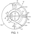
- Fig 1 shows a pipe scanning apparatus 10 surrounding a pipeline 12 (shown in section).
- the scanning apparatus comprises a pair of hinged housings 14a & 14b which open and close by means of hydraulic apparatus 16. When the housings are open the apparatus may be moved around the pipe to be scanned and then closed around it.
- a source of gamma radiation 18 is located within housing 14a together with collimation and shielding to emit a collimated cone of radiation towards the detector array 20.
- An arcuate array 20 of 95 radiation detectors 22 (only five of which are shown, for illustration purposes) is located in housing 14b.
- the detectors comprise scintillation crystals, each coupled to a photodetector.
- the source and the detector array are fixed in relation to each other but are rotatable around the pipeline in the direction of arrows A.
- Each detector of the detector array detects radiation from the source which has passed along a portion of a cone-shaped path between the source and the detector.
- a number of radiation paths may be defined, each radiation path being between the source and each detector in the detector array.
- Each detector is directed towards the source and set within collimation and shielding materials to minimise its detection of scattered radiation.
- detector 22a is located in the centre of the array, and the line of sight from the source to detector 22a follows the centre line between the detector array and the source.
- Detectors 22b and 22c form a conjugate pair, which are each offset from the centre line by angle ⁇ 2.
- detectors 22d and 22e form a conjugate pair, which are each offset from the centre line by angle ⁇ 2. These five detectors are shown only for illustrative purposes.
- Detector array 20 consists, in this example, of 95 detectors, including 47 conjugate pairs.
- the radiation is attenuated by the material of the pipe wall so that the radiation detected by a radiation detector in that path is less than the radiation detected by a detector located in a path which intersects less of the pipe material.
- information can be collected about the density of material along each radiation path and, by means of the rotation of the source and detector array and using a tomography algorithm, an image of the pipeline wall thickness may be assembled.
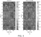
- Fig 3 shows a representation of a coloured matrix of individual detector number n (rows) and angle of source to the pipeline (columns). It will be appreciated that the coloured matrix represented as grey-scale in Fig 1 may lose some detail from its original coloured form.
- T Count rates are number of counts per unit time, where unit time may be expressed in seconds or as the count period if all count periods are of equal duration.
- data is collected from each of the 95 detectors representing the number of counts of radiation received as the source and detector are rotated with respect to the pipe through 360°.
- data is collected at 1 degree increments of rotation.
- Fig 3 clearly shows a sinusoidal pattern in the data.
- a single discontinuity in the density of the pipe material causes a sinusoidal variation in the data because each detector detects the same discontinuity at a different angular position.
- a small steel bar was placed in the pipeline, for demonstration purposes.
- the fan to parallel conversion has rendered the asymmetric curve in Fig 3(a) on the left, as a symmetrical sine wave in the parallel beam data in Fig 3(b) on the right.
- each density variation produces sine waves, which are symmetric compared to the midplane (detector 48). This is important because any 2 detectors that are in symmetric positions compared to detector 48 (e.g.
- conjugate pair 47/49, 46/50, etc.
- a conjugate pair 47/49, 46/50, etc.
- conjugate pairs of detectors read the same attenuation profile at an angular spacing of 180° from each other. Therefore in the case of missing data due to a malfunctioning detector it is possible to use data from the other one of the conjugate pair of which the malfunctioning detector forms a part.
Landscapes
- Health & Medical Sciences (AREA)
- General Physics & Mathematics (AREA)
- Life Sciences & Earth Sciences (AREA)
- Physics & Mathematics (AREA)
- Immunology (AREA)
- Biochemistry (AREA)
- General Health & Medical Sciences (AREA)
- Analytical Chemistry (AREA)
- Chemical & Material Sciences (AREA)
- Pathology (AREA)
- Nuclear Medicine, Radiotherapy & Molecular Imaging (AREA)
- Engineering & Computer Science (AREA)
- Pulmonology (AREA)
- Radiology & Medical Imaging (AREA)
- Theoretical Computer Science (AREA)
- High Energy & Nuclear Physics (AREA)
- Molecular Biology (AREA)
- Spectroscopy & Molecular Physics (AREA)
- Analysing Materials By The Use Of Radiation (AREA)
Claims (9)
- Procédé de balayage qui est un procédé d'identification d'une modification de la masse volumique d'un objet (12), ladite modification représentant une différence entre la masse volumique dudit objet (12) en un premier emplacement et la masse volumique dudit objet (12) en un deuxième emplacement adjacent audit premier emplacement, le procédé comprenant les étapes :a. d'agencement d'une source (18) de rayonnement ionisant et d'un réseau (20) de détecteurs de rayonnement (22), où n est un nombre entier allant de 1 à N, capables de détecter ledit rayonnement de telle manièrei. qu'un rayonnement soit émis à partir de la source (18) dans la direction du réseau (20) de détecteurs de rayonnement (22),ii. qu'un rayonnement soit émis à partir de la source (18) vers l'un quelconque desdits détecteurs de rayonnement (22) le long d'un trajet de rayonnement (24), ledit trajet de rayonnement (24) étant défini à chaque extrémité par la source (18) et la zone de chaque détecteur (22) faisant face à ladite source ;iii. que jusqu'à N desdits trajets de rayonnement (24) puissent traverser ledit objet (12) ; etiv. que ladite source (18) et ledit réseau de détecteurs (20) soient situés dans des positions fixes l'un par rapport à l'autre et mobiles le long d'un trajet de balayage arqué autour dudit objet (12) ;dans lequel ledit réseau de détecteurs (20) comprend une pluralité de N détecteurs de rayonnement (22) D qui sont agencés symétriquement à l'opposé de ladite source (18) de telle manière que des paires conjuguées de détecteurs (22d et 22e, 22b et 22c) soient agencées selon des angles égaux (θ1, θ2) à partir de la source (18) ;b. de positionnement de la source (18) et du réseau de détecteurs (20) en une position connue sur ledit trajet de balayage ;c. de déplacement de ladite source (18) et dudit réseau de détecteurs (20) le long dudit trajet de balayage de sorte à ce que la source (18) et le réseau de détecteurs (20) tournent de 360 degrés autour dudit objet (12) ;d. d'acquisition de données de comptage auprès de chaque détecteur (22) en une pluralité de positions sur ledit trajet de balayage, lesdites données de comptage étant liées au nombre de photons de rayonnement émis par la source (18) qui ont été détectés par ledit détecteur (22) durant la période de comptage ;e. de conversion de données de comptage acquises par chaque détecteur (22) en chaque position au moyen d'un algorithme de conversion de faisceau en éventail à parallèle en données de comptage converties ;f. de sélection de données de comptage à partir d'au moins un détecteur (22) de chacune desdites paires conjuguées (22d et 22e, 22b et 22c) ;g. de dérivation d'informations concernant la masse volumique de l'objet (12) en différentes positions dans le plan du trajet de balayage à partir desdites données de comptage,le procédé comprenant en outre une étape d'étalonnage des détecteurs (22), l'étape d'étalonnage incluant l'obtention d'un balayage spectral d'énergie pour chaque détecteur (22) dans le réseau (20),
caractérisé en ce que
des informations issues du balayage spectral d'énergie sont utilisées pour identifier un détecteur (22) cassé ou défectueux et, lorsque le détecteur cassé ou défectueux a été identifié, des données issues de son détecteur conjugué apparié sont sélectionnées dans l'étape (f). - Procédé selon la revendication 1, dans lequel des données de comptage sont sélectionnées à partir d'au moins un détecteur (22) de chacune desdites paires conjuguées (22d et 22e, 22b et 22c) sur la base des données de comptage comptées par chacun desdits détecteurs (22).
- Procédé selon la revendication 1 ou la revendication 2, dans lequel les données de comptage acquises par chaque détecteur (22) d'une paire conjuguée (22d et 22e, 22b et 22c) sont comparées afin de déterminer si l'un ou l'autre desdits détecteurs (22) est défectueux.
- Procédé selon l'une quelconque des revendications précédentes, dans lequel des données de comptage issues d'un détecteur (22) sont comparées à une gamme prédéterminée de valeurs de comptages qui seraient attendues du détecteur (22) dans le but de déterminer si le détecteur (22) est défectueux.
- Procédé selon l'une quelconque des revendications précédentes, dans lequel ledit étalonnage est mis en oeuvre en l'absence de l'objet (12) devant être balayé.
- Procédé selon l'une quelconque des revendications précédentes, dans lequel l'étape d'étalonnage est mise en oeuvre dans les mêmes ou substantiellement les mêmes conditions environnementales que celles qui seront utilisées pour le balayage.
- Procédé selon l'une quelconque des revendications précédentes, dans lequel des informations issues de l'étalonnage sont utilisées pour identifier quel détecteur (22) d'une paire conjuguée de détecteurs (22d et 22e, 22b et 22c) offre la plus haute résolution de la paire.
- Procédé selon la revendication 7, dans lequel des données de comptage issues du détecteur (22) au sein d'une paire conjuguée (22d et 22e, 22b et 22c) qui offre la plus haute résolution sont sélectionnées dans l'étape (f).
- Appareil de balayage selon l'invention comprenant: une source (18) de rayonnement ionisant et un réseau (20) de détecteurs de rayonnement (22), capables de détecter ledit rayonnement, ladite source (18) et ledit réseau de détecteurs (20) étant agencés de telle manièrei. qu'un rayonnement soit émis à partir de la source (18) dans la direction du réseau (20) de détecteurs de rayonnement (22),ii. qu'un rayonnement soit émis à partir de la source (18) vers l'un quelconque desdits détecteurs de rayonnement (22) le long d'un trajet de rayonnement (24), ledit trajet de rayonnement (24) étant défini à chaque extrémité par la source (18) et la zone de chaque détecteur (22) faisant face à ladite source (18) ;iii. que jusqu'à N desdits trajets de rayonnement (24) puissent traverser un objet (12) qui doit être balayé ; etiv. que ladite source (18) et ledit réseau de détecteurs (20) soient situés dans des positions fixes l'un par rapport à l'autre et mobiles le long d'un trajet de balayage arqué autour dudit objet (12) ;dans lequel ledit réseau de détecteurs (20) comprend une pluralité de N détecteurs de rayonnement (22) D qui sont agencés symétriquement à l'opposé de ladite source (18) de telle manière que des paires conjuguées de détecteurs (22d et 22e, 22b et 22c) soient agencées selon des angles égaux à partir de la source (18) ;
des moyens pour déplacer ladite source (18) et ledit réseau de détecteurs (20) le long dudit trajet de balayage (24) de sorte à ce que la source (18) et le réseau de détecteurs (20) tournent de 360 degrés autour dudit objet (12) ;
un moyen de traitement de données qui est programmé poura. acquérir des données de comptage auprès de chaque détecteur (22), en une pluralité de positions sur ledit trajet de balayage, lesdites données de comptage étant liées au nombre de photons de rayonnement émis par la source (18) qui ont été détectés par ledit détecteur (22) durant la période de comptage ;b. convertir des données de comptage acquises par chaque détecteur (22) en chaque position au moyen d'un algorithme de conversion de faisceau en éventail à parallèle en données de comptage converties ;c. sélectionner des données de comptage à partir d'au moins un détecteur (22) de chacune desdites paires conjuguées (22d et 22e, 22b et 22c) ; etd. dériver des informations concernant la masse volumique de l'objet (12) en différentes positions dans le plan du trajet de balayage à partir desdites données de comptage,dans lequel le moyen de traitement de données est en outre programmé pour étalonner les détecteurs (22),
dans lequel l'étalonnage inclut l'obtention d'un balayage spectral d'énergie pour chaque détecteur (22) dans le réseau (20),
caractérisé en ce que
des informations issues du balayage spectral d'énergie sont utilisées pour identifier un détecteur (22) cassé ou défectueux et, lorsque le détecteur cassé ou défectueux a été identifié, des données issues de son détecteur conjugué apparié sont sélectionnées.
Applications Claiming Priority (3)
| Application Number | Priority Date | Filing Date | Title |
|---|---|---|---|
| GB201322946A GB201322946D0 (en) | 2013-12-23 | 2013-12-23 | Scanning method |
| GB201400103A GB201400103D0 (en) | 2014-01-03 | 2014-01-03 | Scanning method |
| PCT/GB2014/053767 WO2015097451A1 (fr) | 2013-12-23 | 2014-12-18 | Procédé de balayage |
Publications (2)
| Publication Number | Publication Date |
|---|---|
| EP3087376A1 EP3087376A1 (fr) | 2016-11-02 |
| EP3087376B1 true EP3087376B1 (fr) | 2020-02-05 |
Family
ID=52273353
Family Applications (1)
| Application Number | Title | Priority Date | Filing Date |
|---|---|---|---|
| EP14821250.9A Active EP3087376B1 (fr) | 2013-12-23 | 2014-12-18 | Procédé de balayage |
Country Status (4)
| Country | Link |
|---|---|
| US (1) | US10067076B2 (fr) |
| EP (1) | EP3087376B1 (fr) |
| GB (1) | GB2521768B (fr) |
| WO (1) | WO2015097451A1 (fr) |
Families Citing this family (10)
| Publication number | Priority date | Publication date | Assignee | Title |
|---|---|---|---|---|
| JP2015501435A (ja) | 2011-11-02 | 2015-01-15 | ジョンソン、マッセイ、パブリック、リミテッド、カンパニーJohnson Matthey Publiclimited Company | スキャン方法及び装置 |
| US9869647B2 (en) * | 2013-12-23 | 2018-01-16 | Johnson Matthey Public Limited Company | Scanning method |
| JP7027253B2 (ja) | 2018-05-30 | 2022-03-01 | 新光電気工業株式会社 | ループ型ヒートパイプ及びその製造方法 |
| CN113474642B (zh) * | 2019-02-28 | 2024-05-03 | 富士胶片株式会社 | 校正方法、校正装置、放射线图像摄影系统及存储介质 |
| CN109738465B (zh) * | 2019-03-07 | 2024-10-22 | 北京航星机器制造有限公司 | 一种ct探测装置及系统 |
| GB201909987D0 (en) * | 2019-07-11 | 2019-08-28 | Univ Surrey | Apparatus and methods for non-reciprocal broken ray tomography |
| CN112748040B (zh) * | 2020-12-24 | 2023-11-10 | 郑州工程技术学院 | 一种浆体管道输送密度变化探测计及探测方法 |
| US12416588B2 (en) | 2021-03-22 | 2025-09-16 | Ecolab Usa Inc. | Separation column inspection using off axis gamma scanning |
| WO2023023057A1 (fr) * | 2021-08-16 | 2023-02-23 | Oceaneering International, Inc. | Récipient sous pression hybride |
| CN116930223A (zh) * | 2023-07-24 | 2023-10-24 | 中国原子能科学研究院 | 一种探伤机检定方法、装置及系统 |
Family Cites Families (24)
| Publication number | Priority date | Publication date | Assignee | Title |
|---|---|---|---|---|
| GB1493593A (en) | 1974-01-31 | 1977-11-30 | Emi Ltd | Radiography |
| DE2627885A1 (de) | 1976-06-22 | 1978-01-05 | Philips Patentverwaltung | Anordnung zur ermittlung der raeumlichen verteilung der absorption von strahlung in einer ebene eines koerpers |
| GB1584954A (en) | 1976-08-17 | 1981-02-18 | Emi Ltd | Radiography |
| US4338521A (en) | 1980-05-09 | 1982-07-06 | General Electric Company | Modular radiation detector array and module |
| US4712178A (en) | 1984-11-28 | 1987-12-08 | Picker International Inc. | Malfunctioning computed tomography detector correction method |
| JPH0323847A (ja) * | 1989-06-21 | 1991-01-31 | Toshiba Corp | X線ctスキャナ装置 |
| US5533081A (en) | 1995-01-17 | 1996-07-02 | General Electric Company | Guided ringfix algorithm for image reconstruction |
| US7453066B2 (en) * | 2001-01-06 | 2008-11-18 | Koninklijke Philips Electronics N.V. | Method and apparatus to recover a dead pixel in digital imaging systems |
| EP1241470B1 (fr) * | 2001-03-14 | 2003-09-24 | YXLON International X-Ray GmbH | Dispositif de mesure du transfert d'impulsion lors de la diffusion élastique de quantas de rayons x dans la région d' un conteneur à inspecter |
| DE10143045B4 (de) * | 2001-09-03 | 2006-11-02 | Siemens Ag | Verfahren und zur Durchführung dieses Verfahrens ausgebildete medizinische Einrichtung |
| DE10339486A1 (de) * | 2003-08-27 | 2005-03-31 | Siemens Ag | Verfahren zum Ermitteln und Lokalisieren von störobjektebedingten Messsystemfehlern in der Computertomographie |
| US7142636B2 (en) * | 2003-09-23 | 2006-11-28 | General Electric Company | System and method for defective detector cell and DAS channel correction |
| JP4299749B2 (ja) * | 2004-09-01 | 2009-07-22 | ジーイー・メディカル・システムズ・グローバル・テクノロジー・カンパニー・エルエルシー | Ct画像の再構成方法及びct装置並びにプログラム |
| US20060067471A1 (en) * | 2004-09-30 | 2006-03-30 | General Electric Company | Linear array detector system and inspection method |
| JP4937927B2 (ja) * | 2005-12-28 | 2012-05-23 | 株式会社日立メディコ | X線ct装置とx線ct装置における撮像条件決定方法 |
| EP1985998A1 (fr) * | 2007-04-26 | 2008-10-29 | Hitachi-GE Nuclear Energy, Ltd. | Procédé d'inspection de tuyaux, et appareil d'inspection non destructrice radiographique |
| DE112009002256T5 (de) * | 2008-09-19 | 2011-09-29 | Analogic Corporation | Inspektion einer Pipeline |
| US8158951B2 (en) * | 2009-02-03 | 2012-04-17 | General Electric Company | Apparatus and methods for evaluating operation of pixelated detectors |
| JP5702586B2 (ja) * | 2010-02-04 | 2015-04-15 | 富士フイルム株式会社 | 放射線撮影システム |
| EP3255461B1 (fr) * | 2010-04-13 | 2020-10-14 | VEGA Grieshaber KG | Diagnostic de détecteurs radiométriques |
| KR101149000B1 (ko) * | 2010-12-02 | 2012-05-23 | 한국원자력연구원 | 제한각 이동형 산업용 감마선 단층촬영장치 |
| JP2015501435A (ja) * | 2011-11-02 | 2015-01-15 | ジョンソン、マッセイ、パブリック、リミテッド、カンパニーJohnson Matthey Publiclimited Company | スキャン方法及び装置 |
| US9086366B2 (en) * | 2012-02-15 | 2015-07-21 | L-3 Communications Security And Detection Systems, Inc. | Determining a material property based on scattered radiation |
| US9528947B2 (en) * | 2012-05-14 | 2016-12-27 | Samsung Electronics Co., Ltd. | Calibration method of radiation detecting apparatus, radiation imaging apparatus and control method of radiation imaging apparatus |
-
2014
- 2014-12-18 EP EP14821250.9A patent/EP3087376B1/fr active Active
- 2014-12-18 GB GB1422660.9A patent/GB2521768B/en active Active
- 2014-12-18 WO PCT/GB2014/053767 patent/WO2015097451A1/fr not_active Ceased
- 2014-12-18 US US15/101,953 patent/US10067076B2/en active Active
Non-Patent Citations (1)
| Title |
|---|
| None * |
Also Published As
| Publication number | Publication date |
|---|---|
| US20160313261A1 (en) | 2016-10-27 |
| EP3087376A1 (fr) | 2016-11-02 |
| US10067076B2 (en) | 2018-09-04 |
| GB2521768A (en) | 2015-07-01 |
| GB2521768B (en) | 2017-06-14 |
| WO2015097451A1 (fr) | 2015-07-02 |
Similar Documents
| Publication | Publication Date | Title |
|---|---|---|
| EP3087377B1 (fr) | Procédé de balayage | |
| EP3087376B1 (fr) | Procédé de balayage | |
| US11474053B2 (en) | Scanning method and apparatus comprising a buoyancy material and a remotely operated vehicle (ROV) for scanning an underwater pipeline or a process vessel | |
| AU2014372313B2 (en) | Scanning instrument | |
| US11262462B2 (en) | Detection method and detector apparatus for correcting count rate for dead time |
Legal Events
| Date | Code | Title | Description |
|---|---|---|---|
| PUAI | Public reference made under article 153(3) epc to a published international application that has entered the european phase |
Free format text: ORIGINAL CODE: 0009012 |
|
| 17P | Request for examination filed |
Effective date: 20160513 |
|
| AK | Designated contracting states |
Kind code of ref document: A1 Designated state(s): AL AT BE BG CH CY CZ DE DK EE ES FI FR GB GR HR HU IE IS IT LI LT LU LV MC MK MT NL NO PL PT RO RS SE SI SK SM TR |
|
| AX | Request for extension of the european patent |
Extension state: BA ME |
|
| DAX | Request for extension of the european patent (deleted) | ||
| STAA | Information on the status of an ep patent application or granted ep patent |
Free format text: STATUS: EXAMINATION IS IN PROGRESS |
|
| 17Q | First examination report despatched |
Effective date: 20180307 |
|
| REG | Reference to a national code |
Ref country code: DE Ref legal event code: R079 Ref document number: 602014060659 Country of ref document: DE Free format text: PREVIOUS MAIN CLASS: G01N0023040000 Ipc: G01N0023046000 |
|
| RIC1 | Information provided on ipc code assigned before grant |
Ipc: G01N 23/046 20180101AFI20190628BHEP Ipc: A61B 6/00 20060101ALI20190628BHEP |
|
| GRAP | Despatch of communication of intention to grant a patent |
Free format text: ORIGINAL CODE: EPIDOSNIGR1 |
|
| STAA | Information on the status of an ep patent application or granted ep patent |
Free format text: STATUS: GRANT OF PATENT IS INTENDED |
|
| INTG | Intention to grant announced |
Effective date: 20191001 |
|
| GRAS | Grant fee paid |
Free format text: ORIGINAL CODE: EPIDOSNIGR3 |
|
| GRAA | (expected) grant |
Free format text: ORIGINAL CODE: 0009210 |
|
| STAA | Information on the status of an ep patent application or granted ep patent |
Free format text: STATUS: THE PATENT HAS BEEN GRANTED |
|
| RBV | Designated contracting states (corrected) |
Designated state(s): AL AT BE BG CH CY CZ DE DK EE ES FI FR GR HR HU IE IS IT LI LT LU LV MC MK MT NL NO PL PT RO RS SE SI SK SM TR |
|
| AK | Designated contracting states |
Kind code of ref document: B1 Designated state(s): AL AT BE BG CH CY CZ DE DK EE ES FI FR GR HR HU IE IS IT LI LT LU LV MC MK MT NL NO PL PT RO RS SE SI SK SM TR |
|
| REG | Reference to a national code |
Ref country code: AT Ref legal event code: REF Ref document number: 1230269 Country of ref document: AT Kind code of ref document: T Effective date: 20200215 |
|
| REG | Reference to a national code |
Ref country code: DE Ref legal event code: R096 Ref document number: 602014060659 Country of ref document: DE |
|
| REG | Reference to a national code |
Ref country code: IE Ref legal event code: FG4D |
|
| REG | Reference to a national code |
Ref country code: NO Ref legal event code: T2 Effective date: 20200205 |
|
| REG | Reference to a national code |
Ref country code: CH Ref legal event code: EP |
|
| REG | Reference to a national code |
Ref country code: NL Ref legal event code: MP Effective date: 20200205 |
|
| PG25 | Lapsed in a contracting state [announced via postgrant information from national office to epo] |
Ref country code: RS Free format text: LAPSE BECAUSE OF FAILURE TO SUBMIT A TRANSLATION OF THE DESCRIPTION OR TO PAY THE FEE WITHIN THE PRESCRIBED TIME-LIMIT Effective date: 20200205 Ref country code: FI Free format text: LAPSE BECAUSE OF FAILURE TO SUBMIT A TRANSLATION OF THE DESCRIPTION OR TO PAY THE FEE WITHIN THE PRESCRIBED TIME-LIMIT Effective date: 20200205 Ref country code: PT Free format text: LAPSE BECAUSE OF FAILURE TO SUBMIT A TRANSLATION OF THE DESCRIPTION OR TO PAY THE FEE WITHIN THE PRESCRIBED TIME-LIMIT Effective date: 20200628 |
|
| REG | Reference to a national code |
Ref country code: LT Ref legal event code: MG4D |
|
| PG25 | Lapsed in a contracting state [announced via postgrant information from national office to epo] |
Ref country code: BG Free format text: LAPSE BECAUSE OF FAILURE TO SUBMIT A TRANSLATION OF THE DESCRIPTION OR TO PAY THE FEE WITHIN THE PRESCRIBED TIME-LIMIT Effective date: 20200505 Ref country code: LV Free format text: LAPSE BECAUSE OF FAILURE TO SUBMIT A TRANSLATION OF THE DESCRIPTION OR TO PAY THE FEE WITHIN THE PRESCRIBED TIME-LIMIT Effective date: 20200205 Ref country code: SE Free format text: LAPSE BECAUSE OF FAILURE TO SUBMIT A TRANSLATION OF THE DESCRIPTION OR TO PAY THE FEE WITHIN THE PRESCRIBED TIME-LIMIT Effective date: 20200205 Ref country code: HR Free format text: LAPSE BECAUSE OF FAILURE TO SUBMIT A TRANSLATION OF THE DESCRIPTION OR TO PAY THE FEE WITHIN THE PRESCRIBED TIME-LIMIT Effective date: 20200205 Ref country code: GR Free format text: LAPSE BECAUSE OF FAILURE TO SUBMIT A TRANSLATION OF THE DESCRIPTION OR TO PAY THE FEE WITHIN THE PRESCRIBED TIME-LIMIT Effective date: 20200506 Ref country code: IS Free format text: LAPSE BECAUSE OF FAILURE TO SUBMIT A TRANSLATION OF THE DESCRIPTION OR TO PAY THE FEE WITHIN THE PRESCRIBED TIME-LIMIT Effective date: 20200605 |
|
| PG25 | Lapsed in a contracting state [announced via postgrant information from national office to epo] |
Ref country code: NL Free format text: LAPSE BECAUSE OF FAILURE TO SUBMIT A TRANSLATION OF THE DESCRIPTION OR TO PAY THE FEE WITHIN THE PRESCRIBED TIME-LIMIT Effective date: 20200205 |
|
| PG25 | Lapsed in a contracting state [announced via postgrant information from national office to epo] |
Ref country code: SK Free format text: LAPSE BECAUSE OF FAILURE TO SUBMIT A TRANSLATION OF THE DESCRIPTION OR TO PAY THE FEE WITHIN THE PRESCRIBED TIME-LIMIT Effective date: 20200205 Ref country code: CZ Free format text: LAPSE BECAUSE OF FAILURE TO SUBMIT A TRANSLATION OF THE DESCRIPTION OR TO PAY THE FEE WITHIN THE PRESCRIBED TIME-LIMIT Effective date: 20200205 Ref country code: RO Free format text: LAPSE BECAUSE OF FAILURE TO SUBMIT A TRANSLATION OF THE DESCRIPTION OR TO PAY THE FEE WITHIN THE PRESCRIBED TIME-LIMIT Effective date: 20200205 Ref country code: ES Free format text: LAPSE BECAUSE OF FAILURE TO SUBMIT A TRANSLATION OF THE DESCRIPTION OR TO PAY THE FEE WITHIN THE PRESCRIBED TIME-LIMIT Effective date: 20200205 Ref country code: SM Free format text: LAPSE BECAUSE OF FAILURE TO SUBMIT A TRANSLATION OF THE DESCRIPTION OR TO PAY THE FEE WITHIN THE PRESCRIBED TIME-LIMIT Effective date: 20200205 Ref country code: EE Free format text: LAPSE BECAUSE OF FAILURE TO SUBMIT A TRANSLATION OF THE DESCRIPTION OR TO PAY THE FEE WITHIN THE PRESCRIBED TIME-LIMIT Effective date: 20200205 Ref country code: LT Free format text: LAPSE BECAUSE OF FAILURE TO SUBMIT A TRANSLATION OF THE DESCRIPTION OR TO PAY THE FEE WITHIN THE PRESCRIBED TIME-LIMIT Effective date: 20200205 Ref country code: DK Free format text: LAPSE BECAUSE OF FAILURE TO SUBMIT A TRANSLATION OF THE DESCRIPTION OR TO PAY THE FEE WITHIN THE PRESCRIBED TIME-LIMIT Effective date: 20200205 |
|
| REG | Reference to a national code |
Ref country code: DE Ref legal event code: R097 Ref document number: 602014060659 Country of ref document: DE |
|
| REG | Reference to a national code |
Ref country code: AT Ref legal event code: MK05 Ref document number: 1230269 Country of ref document: AT Kind code of ref document: T Effective date: 20200205 |
|
| PLBE | No opposition filed within time limit |
Free format text: ORIGINAL CODE: 0009261 |
|
| STAA | Information on the status of an ep patent application or granted ep patent |
Free format text: STATUS: NO OPPOSITION FILED WITHIN TIME LIMIT |
|
| 26N | No opposition filed |
Effective date: 20201106 |
|
| PG25 | Lapsed in a contracting state [announced via postgrant information from national office to epo] |
Ref country code: AT Free format text: LAPSE BECAUSE OF FAILURE TO SUBMIT A TRANSLATION OF THE DESCRIPTION OR TO PAY THE FEE WITHIN THE PRESCRIBED TIME-LIMIT Effective date: 20200205 Ref country code: IT Free format text: LAPSE BECAUSE OF FAILURE TO SUBMIT A TRANSLATION OF THE DESCRIPTION OR TO PAY THE FEE WITHIN THE PRESCRIBED TIME-LIMIT Effective date: 20200205 |
|
| PG25 | Lapsed in a contracting state [announced via postgrant information from national office to epo] |
Ref country code: PL Free format text: LAPSE BECAUSE OF FAILURE TO SUBMIT A TRANSLATION OF THE DESCRIPTION OR TO PAY THE FEE WITHIN THE PRESCRIBED TIME-LIMIT Effective date: 20200205 Ref country code: SI Free format text: LAPSE BECAUSE OF FAILURE TO SUBMIT A TRANSLATION OF THE DESCRIPTION OR TO PAY THE FEE WITHIN THE PRESCRIBED TIME-LIMIT Effective date: 20200205 |
|
| REG | Reference to a national code |
Ref country code: CH Ref legal event code: PL |
|
| PG25 | Lapsed in a contracting state [announced via postgrant information from national office to epo] |
Ref country code: MC Free format text: LAPSE BECAUSE OF FAILURE TO SUBMIT A TRANSLATION OF THE DESCRIPTION OR TO PAY THE FEE WITHIN THE PRESCRIBED TIME-LIMIT Effective date: 20200205 |
|
| REG | Reference to a national code |
Ref country code: BE Ref legal event code: MM Effective date: 20201231 |
|
| PG25 | Lapsed in a contracting state [announced via postgrant information from national office to epo] |
Ref country code: IE Free format text: LAPSE BECAUSE OF NON-PAYMENT OF DUE FEES Effective date: 20201218 Ref country code: LU Free format text: LAPSE BECAUSE OF NON-PAYMENT OF DUE FEES Effective date: 20201218 |
|
| PG25 | Lapsed in a contracting state [announced via postgrant information from national office to epo] |
Ref country code: LI Free format text: LAPSE BECAUSE OF NON-PAYMENT OF DUE FEES Effective date: 20201231 Ref country code: CH Free format text: LAPSE BECAUSE OF NON-PAYMENT OF DUE FEES Effective date: 20201231 |
|
| PG25 | Lapsed in a contracting state [announced via postgrant information from national office to epo] |
Ref country code: TR Free format text: LAPSE BECAUSE OF FAILURE TO SUBMIT A TRANSLATION OF THE DESCRIPTION OR TO PAY THE FEE WITHIN THE PRESCRIBED TIME-LIMIT Effective date: 20200205 Ref country code: MT Free format text: LAPSE BECAUSE OF FAILURE TO SUBMIT A TRANSLATION OF THE DESCRIPTION OR TO PAY THE FEE WITHIN THE PRESCRIBED TIME-LIMIT Effective date: 20200205 Ref country code: CY Free format text: LAPSE BECAUSE OF FAILURE TO SUBMIT A TRANSLATION OF THE DESCRIPTION OR TO PAY THE FEE WITHIN THE PRESCRIBED TIME-LIMIT Effective date: 20200205 |
|
| PG25 | Lapsed in a contracting state [announced via postgrant information from national office to epo] |
Ref country code: MK Free format text: LAPSE BECAUSE OF FAILURE TO SUBMIT A TRANSLATION OF THE DESCRIPTION OR TO PAY THE FEE WITHIN THE PRESCRIBED TIME-LIMIT Effective date: 20200205 Ref country code: AL Free format text: LAPSE BECAUSE OF FAILURE TO SUBMIT A TRANSLATION OF THE DESCRIPTION OR TO PAY THE FEE WITHIN THE PRESCRIBED TIME-LIMIT Effective date: 20200205 |
|
| PG25 | Lapsed in a contracting state [announced via postgrant information from national office to epo] |
Ref country code: BE Free format text: LAPSE BECAUSE OF NON-PAYMENT OF DUE FEES Effective date: 20201231 |
|
| P01 | Opt-out of the competence of the unified patent court (upc) registered |
Effective date: 20230526 |
|
| REG | Reference to a national code |
Ref country code: DE Ref legal event code: R082 Ref document number: 602014060659 Country of ref document: DE Representative=s name: MURGITROYD GERMANY PATENTANWALTSGESELLSCHAFT M, DE |
|
| REG | Reference to a national code |
Ref country code: DE Ref legal event code: R081 Ref document number: 602014060659 Country of ref document: DE Owner name: TRACERCO LTD., GB Free format text: FORMER OWNER: JOHNSON MATTHEY PUBLIC LIMITED COMPANY, LONDON, GB |
|
| REG | Reference to a national code |
Ref country code: NO Ref legal event code: CREP Representative=s name: MURGITROYD & COMPANY, MANNERHEIMVAEGEN 12 B, 5TR Ref country code: NO Ref legal event code: CHAD Owner name: TRACERCO LIMITED, GB |
|
| PGFP | Annual fee paid to national office [announced via postgrant information from national office to epo] |
Ref country code: NO Payment date: 20260205 Year of fee payment: 12 Ref country code: DE Payment date: 20260130 Year of fee payment: 12 |
|
| PGFP | Annual fee paid to national office [announced via postgrant information from national office to epo] |
Ref country code: FR Payment date: 20260203 Year of fee payment: 12 |