EP3087409B1 - Lokalisierungssystem - Google Patents
Lokalisierungssystem Download PDFInfo
- Publication number
- EP3087409B1 EP3087409B1 EP15702377.1A EP15702377A EP3087409B1 EP 3087409 B1 EP3087409 B1 EP 3087409B1 EP 15702377 A EP15702377 A EP 15702377A EP 3087409 B1 EP3087409 B1 EP 3087409B1
- Authority
- EP
- European Patent Office
- Prior art keywords
- beacon
- tag
- message
- information
- magnetic induction
- Prior art date
- Legal status (The legal status is an assumption and is not a legal conclusion. Google has not performed a legal analysis and makes no representation as to the accuracy of the status listed.)
- Active
Links
Images

Classifications
-
- G—PHYSICS
- G01—MEASURING; TESTING
- G01S—RADIO DIRECTION-FINDING; RADIO NAVIGATION; DETERMINING DISTANCE OR VELOCITY BY USE OF RADIO WAVES; LOCATING OR PRESENCE-DETECTING BY USE OF THE REFLECTION OR RERADIATION OF RADIO WAVES; ANALOGOUS ARRANGEMENTS USING OTHER WAVES
- G01S5/00—Position-fixing by co-ordinating two or more direction or position line determinations; Position-fixing by co-ordinating two or more distance determinations
- G01S5/02—Position-fixing by co-ordinating two or more direction or position line determinations; Position-fixing by co-ordinating two or more distance determinations using radio waves
- G01S5/0257—Hybrid positioning
- G01S5/0263—Hybrid positioning by combining or switching between positions derived from two or more separate positioning systems
- G01S5/0264—Hybrid positioning by combining or switching between positions derived from two or more separate positioning systems at least one of the systems being a non-radio wave positioning system
-
- G—PHYSICS
- G01—MEASURING; TESTING
- G01S—RADIO DIRECTION-FINDING; RADIO NAVIGATION; DETERMINING DISTANCE OR VELOCITY BY USE OF RADIO WAVES; LOCATING OR PRESENCE-DETECTING BY USE OF THE REFLECTION OR RERADIATION OF RADIO WAVES; ANALOGOUS ARRANGEMENTS USING OTHER WAVES
- G01S13/00—Systems using the reflection or reradiation of radio waves, e.g. radar systems; Analogous systems using reflection or reradiation of waves whose nature or wavelength is irrelevant or unspecified
- G01S13/74—Systems using reradiation of radio waves, e.g. secondary radar systems; Analogous systems
-
- G—PHYSICS
- G01—MEASURING; TESTING
- G01S—RADIO DIRECTION-FINDING; RADIO NAVIGATION; DETERMINING DISTANCE OR VELOCITY BY USE OF RADIO WAVES; LOCATING OR PRESENCE-DETECTING BY USE OF THE REFLECTION OR RERADIATION OF RADIO WAVES; ANALOGOUS ARRANGEMENTS USING OTHER WAVES
- G01S5/00—Position-fixing by co-ordinating two or more direction or position line determinations; Position-fixing by co-ordinating two or more distance determinations
- G01S5/02—Position-fixing by co-ordinating two or more direction or position line determinations; Position-fixing by co-ordinating two or more distance determinations using radio waves
- G01S5/0205—Details
- G01S5/0236—Assistance data, e.g. base station almanac
-
- G—PHYSICS
- G01—MEASURING; TESTING
- G01S—RADIO DIRECTION-FINDING; RADIO NAVIGATION; DETERMINING DISTANCE OR VELOCITY BY USE OF RADIO WAVES; LOCATING OR PRESENCE-DETECTING BY USE OF THE REFLECTION OR RERADIATION OF RADIO WAVES; ANALOGOUS ARRANGEMENTS USING OTHER WAVES
- G01S5/00—Position-fixing by co-ordinating two or more direction or position line determinations; Position-fixing by co-ordinating two or more distance determinations
- G01S5/02—Position-fixing by co-ordinating two or more direction or position line determinations; Position-fixing by co-ordinating two or more distance determinations using radio waves
- G01S5/0294—Trajectory determination or predictive filtering, e.g. target tracking or Kalman filtering
-
- G—PHYSICS
- G01—MEASURING; TESTING
- G01V—GEOPHYSICS; GRAVITATIONAL MEASUREMENTS; DETECTING MASSES OR OBJECTS; TAGS
- G01V15/00—Tags attached to, or associated with, an object, in order to enable detection of the object
-
- G—PHYSICS
- G07—CHECKING-DEVICES
- G07C—TIME OR ATTENDANCE REGISTERS; REGISTERING OR INDICATING THE WORKING OF MACHINES; GENERATING RANDOM NUMBERS; VOTING OR LOTTERY APPARATUS; ARRANGEMENTS, SYSTEMS OR APPARATUS FOR CHECKING NOT PROVIDED FOR ELSEWHERE
- G07C9/00—Individual registration on entry or exit
- G07C9/20—Individual registration on entry or exit involving the use of a pass
- G07C9/28—Individual registration on entry or exit involving the use of a pass the pass enabling tracking or indicating presence
-
- G—PHYSICS
- G01—MEASURING; TESTING
- G01V—GEOPHYSICS; GRAVITATIONAL MEASUREMENTS; DETECTING MASSES OR OBJECTS; TAGS
- G01V3/00—Electric or magnetic prospecting or detecting; Measuring magnetic field characteristics of the earth, e.g. declination, deviation
- G01V3/08—Electric or magnetic prospecting or detecting; Measuring magnetic field characteristics of the earth, e.g. declination, deviation operating with magnetic or electric fields produced or modified by objects or geological structures or by detecting devices
- G01V3/10—Electric or magnetic prospecting or detecting; Measuring magnetic field characteristics of the earth, e.g. declination, deviation operating with magnetic or electric fields produced or modified by objects or geological structures or by detecting devices using induction coils
-
- G—PHYSICS
- G01—MEASURING; TESTING
- G01V—GEOPHYSICS; GRAVITATIONAL MEASUREMENTS; DETECTING MASSES OR OBJECTS; TAGS
- G01V3/00—Electric or magnetic prospecting or detecting; Measuring magnetic field characteristics of the earth, e.g. declination, deviation
- G01V3/12—Electric or magnetic prospecting or detecting; Measuring magnetic field characteristics of the earth, e.g. declination, deviation operating with electromagnetic waves
-
- G—PHYSICS
- G07—CHECKING-DEVICES
- G07C—TIME OR ATTENDANCE REGISTERS; REGISTERING OR INDICATING THE WORKING OF MACHINES; GENERATING RANDOM NUMBERS; VOTING OR LOTTERY APPARATUS; ARRANGEMENTS, SYSTEMS OR APPARATUS FOR CHECKING NOT PROVIDED FOR ELSEWHERE
- G07C9/00—Individual registration on entry or exit
- G07C9/00174—Electronically operated locks; Circuits therefor; Nonmechanical keys therefor, e.g. passive or active electrical keys or other data carriers without mechanical keys
- G07C2009/00753—Electronically operated locks; Circuits therefor; Nonmechanical keys therefor, e.g. passive or active electrical keys or other data carriers without mechanical keys operated by active electrical keys
- G07C2009/00769—Electronically operated locks; Circuits therefor; Nonmechanical keys therefor, e.g. passive or active electrical keys or other data carriers without mechanical keys operated by active electrical keys with data transmission performed by wireless means
- G07C2009/00777—Electronically operated locks; Circuits therefor; Nonmechanical keys therefor, e.g. passive or active electrical keys or other data carriers without mechanical keys operated by active electrical keys with data transmission performed by wireless means by induction
Definitions
- the present invention relates to a wireless localisation system for movable objects or persons, such as a system to track the location of patients and/or assets in a facility such as a hospital.
- the invention also relates to a corresponding method, and a tag for use in same.
- WO 2004/051303 A1 discloses a method and a system for monitoring and position determination of objects and/or living beings within an area, such as, e.g. a room in a building or a road tunnel.
- the system comprises a plurality of identification tags equipped with an ultrasonic receiver and radio transmitter which is attached to the objects that have to be monitored.
- the identification tags receive ultrasonic signals whose arrival time they measure. This information together with the identification tags' ID code are transmitted by radio waves to a central unit which calculates the position of each of the identification tags.
- European patent application EP 2 469 298 A1 in the name of the present applicant discloses a method and device for determining location of a target, using mobile tags and fixed beacons, wherein the target location is estimated from a weighted sum of the indications of the received signal power of at least two received signals. It is a disadvantage of this system that multiple received signals must be available to perform RSSI triangulation.
- the publication WO 2013/105589 discloses a method for evaluating a distance between an object and a RFID tag. The current setting of the magnetic field detecting sensitivity level of the tag is modified when magnetic field from a beacon has been detected.
- a method, an identification tag, a system and a computer program product as set forth in the independent claims are provided. Embodiments of the invention are claimed in the dependent claims. According to an aspect of the present invention, there is provided a method for detecting a first tag in an area monitored by one or more beacons, the first tag comprising a magnetic induction module and a transmitter, the method comprising the following steps at the first tag:
- the transmitter comprises a radio frequency transmitter.
- a signal containing location information can be broadcast reliably and efficiently by the identification tag, for instance to the nearest beacon, in order to inform the central system of the identification tag's present location.
- the first beacon message is broadcast by one of the beacons, the one of the beacons being located in a zone, the beacon information comprises information pertaining to the zone, and the conditionally transmitting a localisation message comprises comparing the information to one or more zones stored on the first tag.
- the beacon information comprises an instruction adapted to control an operation of the first tag.
- the beacon information comprises operating range information
- the method further comprises: conditionally on the operating range information, reducing a sensitivity of the magnetic induction module.
- an identification tag that has approached an access control point can be turned into an access badge which will only trigger access authentication if it is brought into a very close range of the beacon (the range covered by the reduced sensitivity of the magnetic induction module).
- the reducing of the sensitivity of the magnetic induction module comprises electronically modifying a tuned circuit of the magnetic induction module by adding or removing a capacitive or inductive component.
- the method according to the present invention further comprises switching the first tag to a continuously receiving mode.
- the identification tag may be configured to operate according to a certain duty cycle in order to save energy, it may be instructed to switch to a full-time responsive mode when it has been put into short range (reduced sensitivity) mode, to reduce the latency of any subsequent access authentication request.
- the method according to the present invention further comprises receiving a second beacon message while the sensitivity is reduced, and transmitting an access request message.
- This embodiment can be used to implement the access authentication request functionality.
- the method according to the present invention further comprises switching a second tag to a beacon mode, wherein the beacon message is received from the second tag.
- a tag owned by a supervisor may temporarily be switched into "beacon mode", whereupon other nearby tags may receive the supervisor's beacon message and enter a "paired" mode.
- the paired state of the first and second tags may be used as a trigger to treat wandering events and access requests by one or both of these tags differently than when the tags are not paired.
- a computer program product comprising code means configured to cause a processor to perform the functions of the first tag in the method according to any of the preceding claims.
- an identification tag for use in a location system for determining a location of the identification tag in an area monitored by at least one beacon, the at least one beacon being adapted to broadcast beacon messages as variations in a magnetic field, which beacon messages comprise beacon information;
- the identification tag comprising: a magnetic induction module configured to convert a varying magnetic field into an electrical signal; a processing module adapted to decode the electrical signal and to extract a first beacon message therefrom; and a transmitter adapted to transmit a localisation message; wherein the tag is configured to transmit a localisation message, conditionally on the beacon information, by means of the transmitter.
- the transmitter comprises a radio frequency transmitter.
- the tag is further configured to selectively adapt a sensitivity of the magnetic induction module in function of operating range information comprised in the beacon information.
- the identification tag further comprises sensitivity switching means configured to electronically modify a tuned circuit of the magnetic induction module by adding or removing a capacitive or inductive component.
- a system comprising a first tag as described above and a beacon for use in the method as described above.
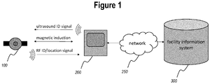
- Figure 1 schematically illustrates a location system comprising beacons and tags according to an embodiment of the present invention.
- a specific application of the location system described herein is a wireless nurse call system for use in hospitals and other institutions where patients may move about, possibly without being fully conscious of their own exact location.
- the invention will be described with reference to such a nurse call system, without intent to limit the scope of the invention to such applications.
- a wireless nurse call system the development of efficient hardware is an important goal, with a view to reducing (battery) power consumption, obtaining a small form factor, and keeping the total cost as low as possible.
- the system should provide a very accurate determination of the tag's location, both in the spatial dimension (high spatial accuracy) and in the time dimension (low latency tracking), such that adequate responses to tracking events can be deployed immediately and at the right place.
- beacons 200 are provided at fixed locations throughout an area in which the location of mobile objects or persons is to be monitored.
- the beacons may generally be mounted to walls, doors, pillars, and the like. They may have a basic user interface comprising a display and one or more keys.
- the mobile objects or persons to be monitored are provided with identification tags (hereinafter also referred to as "tags") 100.
- the beacons 200 emit a signal comprising an identification element, which can be received and decoded by the tags 100.
- the beacons may optionally emit an identification element modulated onto an ultrasound signal.
- Ultrasound communication is based on electromechanically induced vibrations that generate propagating longitudinal acoustic waves. As ultrasound waves are, by definition, in a frequency range beyond the audible range for humans, their use is no hindrance to humans present in the monitored area. Within building environments, ultrasound waves are almost completely blocked by walls (contrary to electromagnetic waves). Ultrasound waves are therefore a suitable signal type to obtain room-level localisation accuracy. If ultrasound localisation is used, the mobile objects or persons to be monitored are provided with tags 100 which comprise an ultrasound receiver. Upon receiving the beacon identification element encoded in the ultrasound signal, the tag 100 will be aware of its location (in the sense of being able to identify the nearest beacon 200 ) down to room-level accuracy, without any need for triangulation.
- the tags according embodiments of the present invention it is a goal of the tags according embodiments of the present invention to detect proximity to sensitive points in the monitored area, such as doors or gates between divisions of a building or building complex, and places where critical objects are kept (e.g., emergency equipment or drugs).
- This function requires a localisation mechanism that is even more accurate, both in terms of spatial resolution and in terms of latency, than the ultrasound-based system described above.
- Embodiments of the present invention are based inter alia on the insight of the inventors that this goal can be met by using magnetic induction to achieve very short-range detection and communication (a typical range extends from approximately 10 cm to approximately 1 m; for some applications, a range up to 5 m may be used).
- the beacons are adapted to receive a beacon signal, including a beacon identification element, by means of magnetic induction, in the form of a varying magnetic field.
- a method of detecting a first tag 100 in an area monitored by one or more beacons 200, the first tag 100 comprising a magnetic induction module 120 and a transmitter 140 comprises the following steps at the first tag: receiving, by means of the magnetic induction module 120, a first beacon message as variations in a magnetic field, the first beacon message comprising beacon information; extracting the beacon information from the first beacon message; and, conditionally on the beacon information, transmitting a localisation message by means of the transmitter 140.
- the beacon message may be received from a beacon 200.
- the beacon message may also be received from another tag (not shown).
- the tag also comprises an ultrasound receiver 110, as described above, for receiving beacon identification messages transmitted by near-by beacons via ultrasound acoustic transmission, as described in more detail above.
- an ultrasound receiver 110 for receiving beacon identification messages transmitted by near-by beacons via ultrasound acoustic transmission, as described in more detail above.
- the tag 100 comprises a transmitter 140 to relay the decoded beacon identification element, along with its own identity, to the central monitoring system.
- the transmitter 140 may include a radio frequency (RF) transmitter adapted to wirelessly communicate the information to a beacon (the same beacon whose identification element was received and/or another beacon within radio range), which is in turn preferably connected to a wired or wireless network 250 that allows it to communicate with a centralized management system 300.
- RF radio frequency
- the transmitter 140 uses the magnetic induction module to transmit the localisation message by producing variations in a magnetic field.
- the identity of the beacon 200 at which the signal of the tag 100 is received provides a clue to the location of the tag 100.
- this localisation step is coarser than the ultrasound-based localisation, because the range of an RF transmission with typical properties (e.g., using the legally permitted transmit power in the unlicensed ISM bands at 434 MHz, 2.4 GHz, or 5 GHz, or the SRD 860 band) will be longer than that of an ultrasound transmission, and will in particular not significantly be constrained by walls.
- beacon identities transmitted in the ultrasound signal need only be unique within the set of beacons with overlapping ultrasound communication ranges. This allows for a shorter "beacon identity" field to be used in the messages conveyed by the ultrasound signals, which in turn leads to a lower average data rate and thus lower power consumption at the transmitter (beacon) and the receiver (tag).
- Whether or not the identification tag 100 transmits a localisation message in response to a given received beacon message is conditional on information in the beacon message.
- Several types of information in the beacon message may be used by the identification tag 100 to make this assessment.
- the behavior of the identification tag may be made location dependent. If the tag is able to determine where it is, it can adapt its behavior accordingly.
- One way of accomplishing this, is be including zone information in the beacon message transmitted by the fixed beacon(s).
- the first beacon message is broadcast by one of the beacons, the one of the beacons being located in a zone
- the beacon information comprises information pertaining to the zone
- the conditionally transmitting a localisation message comprises comparing the information to one or more zones stored on the first tag. Based on this comparison, the identification tag 100 will determine what behavior is required given the zone it is in.
- the identification tag 100 may dispense with the transmission of location messages as long as it determines it is in its home zone, or in a designated silent zone".
- the beacon information may comprise an instruction adapted to control an operation of the first tag. This allows the operator of the system to influence the behavior of the tags according to the time of day, or in response to specific events, such as emergencies.
- the beacon information comprises operating range information
- the method further comprises, conditionally on the operating range information, reducing a sensitivity of the magnetic induction module.
- the tag preferably comprises a coil, coupled to an appropriately tuned electronic circuit, to convert a detected varying magnetic field having a specific target frequency into an electrical signal that may be further processed.
- the reducing of the sensitivity of the magnetic induction module may comprise electronically modifying a tuned circuit of the magnetic induction module by adding or removing a capacitive or inductive component.
- the electronic circuit is preferably designed in such a way that it can be deliberately and reversibly detuned (in particular, by dynamically switching an additional capacitance or inductance into the tuning circuit by means of appropriately controlled transistors). By detuning the tuning circuit, the effective range of the magnetic inductance receiver can be deliberately reduced.
- the tag can discriminate between “general proximity” to the beacon (e.g., walking past a beacon while wearing a tag) and “extreme proximity” to the beacon (e.g., holding the tag up close to the beacon's housing), because any signal received in reduced sensitivity mode is indicative of being in very close range (extreme proximity) of the beacon.
- the "general proximity” may be used to trigger an alert that somebody is approaching a sensitive zone, such as an exit which a monitored person is not authorized to use (thus, it may be detected when patients wander out of their ward or their designated zone).
- the "extreme proximity" may be used as a trigger to perform an authentication that may lead to the opening of a door or a gate and the like.
- the beacon may indicate its type in the signal it emits by magnetic induction.
- the tag may be configured to detune its magnetic induction circuit as described above only when receiving an indication that the beacon is of a type that requires extreme proximity to trigger a particular action.
- the tag may switch to a continuously receiving mode when it switches to reduced sensitivity mode. In that way, the tag becomes a short-range access badge, which is only triggered if it is brought into close range of the access control beacon, without requiring the use of different beacon hardware for access control beacons and for general localisation beacons.
- the tag When in range with reduced sensitivity, the tag may receive a second beacon message, and then transmit an access request message.
- This access request message may be sent directly to the same beacon by means of magnetic induction, if the tag is so configured, or, more preferably, it may be broadcast by RF transmission and picked up by any one of the beacons within RF range or another RF receiver coupled to the central system.
- Access control may be implemented in several different ways. Access to a zone may be restricted, by locking doors that are normally open upon the approach of a non-authorized person, as detected by the localisation signal emitted by this person's tag upon approaching the door's beacon. Conversely, access may be regulated by unlocking doors that are normally locked upon the approach of an authorized person, optionally after performing a "barging" action consisting of triggering the reduced-sensitivity mode of the approaching person's tag, transmitting another beacon message, and receiving an appropriate localisation message from the tag in question.
- a first tag receives the beacon message from a second tag, which is capable of being temporarily switched to a "beacon mode", in which it transmits beacon messages through magnetic induction communication.
- This "beacon mode” thus allows at least unidirectional tag-to-tag communication.
- This feature forms the basis for use cases in which tags are logically paired to one another. Additionally or alternatively, this feature can form the basis for sending short instructions from the second tag to the first tag, such as configuration instructions or activation/deactivation of ancillary features of the first tag (reading light, alarm clock, ).
- the first tag and/or the second tag transmit a pairing message to the monitoring system via one or more fixed beacons, to indicate that the first tag and the second tag are paired or about to be paired.
- the central system may apply different access and alarm rules for the paired tags.
- the paired state of the first and second tags may be used as a trigger to treat wandering events and access requests by one or both of these tags differently. Accordingly, in a hospital scenario, a patient may be granted access to a certain area that is normally restricted, only when his tag is paired with the tag of a nurse, assuming that the nurse's tag is also presented at the access control beacon. In another scenario, a detained person may be allowed to wander around freely in a designated zone as long as his badged is paired with the badge of an approved visitor or a guard.
- the pairing is only a logical state, and not a physical state, it may be useful to alert the users to the paired state by means of indicators on one or both of the tags. These indicators may be visual, such as a lit or blinking LED or an indicator on an LCD screen, or auditory, such as a continuous series of low-volume beeps.
- the paired state may expire after a preset amount of time. Additionally or alternatively, the paired state may be terminated by an instruction entered in the central system. Additionally or alternatively, the paired state may be terminated by a specific interaction with the first tag and/or the second tag (e.g., pushing a button provided for that purpose).
- FIG. 2 illustrates an identification tag for use in a location system for determining a location of the identification tag in an area monitored by at least one beacon, the at least one beacon being adapted to broadcast beacon messages as variations in a magnetic field, which beacon messages comprise beacon information;
- the identification tag comprising: a magnetic induction module 120 configured to convert a varying magnetic field into an electrical signal; a processing module 135 adapted to decode the electrical signal and to extract a first beacon message therefrom; and a transmitter 140 adapted to transmit a localisation message; wherein the tag 100 is configured to transmit a localisation message, conditionally on the beacon information, by means of the transmitter 140.
- the processing module 135 may act as a common front-end and performs synchronization and decodes the respective electrical signals obtained from the electromechanical (ultrasound) signal and the electromagnetic (magnetic induction) signal.
- the hardware used to convert the ultrasound waves into an electrical signal herein also referred to as the ultrasound receiver module 110
- the hardware used to perform magnetic induction coupling herein also referred to as the magnetic induction module 120
- the processing module 135 is further connected to the transmitter 140.
- the processing module 135 decodes the digital signals, so as to retrieve or extract the transmitted information, and carries out the assessment of the conditions for transmission of a localisation message in response to the beacon message.
- the ultrasound receiver module 110 has a channel interface comprising mainly a microphone element with an appropriate frequency response for the used ultrasound signals.
- the magnetic induction module 120 has a channel interface comprising mainly a coil or ferrite antenna and a resonance circuit.
- the functions described hereinabove as pertaining to the processing module 135 may be implemented in dedicated hardware (e.g., ASIC), configurable hardware (e.g., FPGA), programmable components (e.g., a DSP or general purpose processor with appropriate software), or any combination thereof.
- the same component may also include other functions, including parts of the ultrasound receiver module 110 and/or parts of the magnetic induction module 120.
- the present invention also pertains to a computer program, optionally stored on a computer-readable medium, comprising code means adapted to cause a processor to perform the functions of the identification tag 100 as described above.
Landscapes
- Engineering & Computer Science (AREA)
- Radar, Positioning & Navigation (AREA)
- Remote Sensing (AREA)
- Physics & Mathematics (AREA)
- General Physics & Mathematics (AREA)
- Computer Networks & Wireless Communication (AREA)
- Life Sciences & Earth Sciences (AREA)
- General Life Sciences & Earth Sciences (AREA)
- Geophysics (AREA)
- Radar Systems Or Details Thereof (AREA)
- Near-Field Transmission Systems (AREA)
Claims (13)
- Verfahren zur Erfassung einer ersten Marke (100) in einem Bereich, der durch eine oder mehr Baken (200) überwacht ist, wobei die erste Marke (100) ein magnetisches Induktionsmodul (121) und einen Sender (140) umfasst, wobei das Verfahren die folgenden Schritte an der Marke umfasst:- Empfangen, mittels des magnetischen Induktionsmoduls, einer ersten Baken-Nachricht als Variationen in einem Magnetfeld, wobei die erste Baken-Nachricht Baken-Informationen umfasst;- Extrahieren der Baken-Informationen aus der ersten Baken-Nachricht;- bedingt durch die Baken-Informationen, Senden oder Nicht-Senden einer Lokalisierungsnachricht mittels des Senders (140),wobei die Baken-Informationen Betriebsbereichsinformationen umfassen, wobei die Betriebsbereichsinformationen einen Typ der Bake anzeigen, die die erste Baken-Nachricht ausgesendet hat; das Verfahren ferner umfassend: bedingt durch den Typ, Verringern einer Empfindlichkeit des magnetischen Induktionsmoduls (121).
- Verfahren nach Anspruch 1, wobei der Sender (140) einen Funkfrequenzsender umfasst.
- Verfahren nach einem der vorangehenden Ansprüche, wobei die erste Baken-Nachricht durch eine der Baken (200) ausgestrahlt wird, wobei die eine der Baken in einer Zone gelegen ist, wobei die Baken-Informationen Informationen umfassen, die diese Zone betreffen, und wobei das bedingte Senden einer Lokalisierungsnachricht ein Vergleichen der Informationen mit einer oder mehreren Zonen, die auf der ersten Marke (100) gespeichert sind, umfasst.
- Verfahren nach einem der vorangehenden Ansprüche, wobei die Baken-Informationen eine Anweisung umfassen, die angepasst ist, einen Betrieb der ersten Marke (100) zu steuern.
- Verfahren nach einem der vorangehenden Ansprüche, wobei das Verringern der Empfindlichkeit des magnetischen Induktionsmoduls (121) ein elektronisches Modifizieren eines abgestimmten Schwingungskreises des magnetischen Induktionsmoduls (121) durch ein Hinzufügen oder Entfernen einer kapazitiven oder induktiven Komponente umfasst.
- Verfahren nach einem der vorangehenden Ansprüche, ferner umfassend ein Umschalten der ersten Marke (100) in einen fortlaufenden Empfangsmodus.
- Verfahren nach einem der vorangehenden Ansprüche, ferner umfassend ein Empfangen einer zweiten Baken-Nachricht, während die Empfindlichkeit verringert ist, und Senden einer Zugangsanfragenachricht.
- Verfahren nach Anspruch 1, ferner umfassend ein Umschalten einer zweiten Marke in einen Baken-Modus, wobei die erste Baken-Nachricht von der zweiten Marke empfangen wird.
- Rechnerprogrammprodukt, umfassend Codemittel, die konfiguriert sind, einen Prozessor zu veranlassen, an der ersten Marke die Schritte des Verfahrens nach einem der vorangehenden Ansprüche auszuführen.
- Identifikationsmarke (100) zur Verwendung in einem Lokalisierungssystem zur Ermittlung einer Stelle der Identifikationsmarke in einem Bereich, der durch zumindest eine Bake überwacht ist, wobei die zumindest eine Bake angepasst ist, Baken-Nachrichten als Variationen in einem Magnetfeld auszustrahlen, welche Baken-Nachrichten Baken-Informationen umfassen;
die Identifikationsmarke umfassend:- ein magnetisches Induktionsmodul (120), das konfiguriert ist, ein variierendes Magnetfeld in ein elektrisches Signal umzuwandeln;- ein Verarbeitungsmodul (135), das angepasst ist, das elektrische Signal zu dekodieren und eine erste Baken-Nachricht daraus zu extrahieren; und- einen Sender, der angepasst ist, eine Lokalisierungsnachricht zu senden;wobei die Marke konfiguriert ist, mittels des Senders eine Lokalisierungsnachricht zu senden oder nicht zu senden, bedingt durch die Baken-Informationen,
wobei die Baken-Informationen Betriebsbereichsinformationen umfassen, die einen Typ der Bake anzeigen, die die erste Baken-Nachricht ausgesendet hat; und
wobei die Marke ferner konfiguriert ist, eine Empfindlichkeit des magnetischen Induktionsmoduls bedingt durch den Typ zu verringern. - Identifikationsmarke (100) nach Anspruch 10, wobei der Sender einen Funkfrequenzsender umfasst.
- Identifikationsmarke (100) nach Anspruch 10 oder Anspruch 11, ferner umfassend Empfindlichkeitsumschaltmittel, die konfiguriert sind, einen abgestimmten Schwingungskreis des magnetischen Induktionsmoduls (121) durch Hinzufügen oder Entfernen einer kapazitiven oder induktiven Komponente elektronisch zu modifizieren.
- System, umfassend eine erste Marke (100) nach einem der Ansprüche 10-12 und eine Bake (200) zur Verwendung im Verfahren nach einem der Ansprüche 1-8.
Priority Applications (1)
| Application Number | Priority Date | Filing Date | Title |
|---|---|---|---|
| EP15702377.1A EP3087409B1 (de) | 2013-12-24 | 2015-01-05 | Lokalisierungssystem |
Applications Claiming Priority (3)
| Application Number | Priority Date | Filing Date | Title |
|---|---|---|---|
| EP13199600.1A EP2889634B1 (de) | 2013-12-24 | 2013-12-24 | Lokalisierungssystem |
| EP15702377.1A EP3087409B1 (de) | 2013-12-24 | 2015-01-05 | Lokalisierungssystem |
| PCT/EP2015/050069 WO2015097314A1 (en) | 2013-12-24 | 2015-01-05 | Localisation system |
Publications (2)
| Publication Number | Publication Date |
|---|---|
| EP3087409A1 EP3087409A1 (de) | 2016-11-02 |
| EP3087409B1 true EP3087409B1 (de) | 2018-03-14 |
Family
ID=49885068
Family Applications (2)
| Application Number | Title | Priority Date | Filing Date |
|---|---|---|---|
| EP13199600.1A Active EP2889634B1 (de) | 2013-12-24 | 2013-12-24 | Lokalisierungssystem |
| EP15702377.1A Active EP3087409B1 (de) | 2013-12-24 | 2015-01-05 | Lokalisierungssystem |
Family Applications Before (1)
| Application Number | Title | Priority Date | Filing Date |
|---|---|---|---|
| EP13199600.1A Active EP2889634B1 (de) | 2013-12-24 | 2013-12-24 | Lokalisierungssystem |
Country Status (4)
| Country | Link |
|---|---|
| US (1) | US9746543B2 (de) |
| EP (2) | EP2889634B1 (de) |
| CN (1) | CN106104294B (de) |
| WO (1) | WO2015097314A1 (de) |
Families Citing this family (8)
| Publication number | Priority date | Publication date | Assignee | Title |
|---|---|---|---|---|
| US9641969B2 (en) | 2014-07-25 | 2017-05-02 | General Electric Company | Wireless bridge hardware system for active RFID identification and location tracking |
| EP3185033B1 (de) | 2015-12-22 | 2018-09-26 | Televic Healthcare NV | Beaconvorrichtung und zugehörige raumlampeneinheit |
| US20180122214A1 (en) * | 2016-10-27 | 2018-05-03 | Johnson Controls Technology Company | Hand hygiene system |
| EP3343245A1 (de) * | 2016-12-30 | 2018-07-04 | Televic Healthcare NV | Falschalarmvermeidungssystem |
| WO2019144054A1 (en) | 2018-01-19 | 2019-07-25 | Johnson Controls Technology Company | Hand hygiene and surgical scrub system |
| CN108810819B (zh) * | 2018-05-25 | 2021-05-14 | 厦门华方软件科技有限公司 | 一种基于网络通讯的地表定位方法及介质 |
| EP3745373A1 (de) | 2019-05-27 | 2020-12-02 | Televic Healthcare NV | Verfahren und system zur identifizierung eines benutzers einer signalisierungseinheit |
| CN112763970B (zh) * | 2020-12-25 | 2024-10-18 | 京东科技信息技术有限公司 | 定位方法及装置、信标、定位系统、存储介质、移动终端 |
Family Cites Families (27)
| Publication number | Priority date | Publication date | Assignee | Title |
|---|---|---|---|---|
| US5917425A (en) | 1996-01-22 | 1999-06-29 | Wireless Communiations Products, Llc | IR/RF locator |
| US6466131B1 (en) * | 1996-07-30 | 2002-10-15 | Micron Technology, Inc. | Radio frequency data communications device with adjustable receiver sensitivity and method |
| US6970097B2 (en) | 2001-05-10 | 2005-11-29 | Ge Medical Systems Information Technologies, Inc. | Location system using retransmission of identifying information |
| US7030731B2 (en) | 2001-06-14 | 2006-04-18 | Rf Code, Inc. | Wireless identification systems and protocols |
| NO318010B1 (no) | 2002-12-04 | 2005-01-17 | Sonitor Technologies As | Ultralyd lokaliseringssystem |
| US7751829B2 (en) | 2003-09-22 | 2010-07-06 | Fujitsu Limited | Method and apparatus for location determination using mini-beacons |
| US7489242B2 (en) | 2004-07-13 | 2009-02-10 | Tony Hines | RFID multiple range method and system |
| US7295132B2 (en) | 2004-10-16 | 2007-11-13 | International Business Machines Corporation | Self-locating devices via highly directional RFID tags in controlled location |
| KR100778307B1 (ko) * | 2005-02-07 | 2007-11-22 | (주)씨앤드에스 마이크로 웨이브 | 저 전력 리더-태그 통신을 위한 지능형 무선주파수인식시스템 및 그 방법 |
| US20060290519A1 (en) | 2005-06-22 | 2006-12-28 | Boate Alan R | Two-way wireless monitoring system and method |
| WO2007006085A1 (en) * | 2005-07-08 | 2007-01-18 | Roger Becker | Radio frequency identification (rfid) tags and techniques |
| US20070139199A1 (en) | 2005-11-29 | 2007-06-21 | Pango Networks, Inc. | Method and apparatus for an active radio frequency identification tag |
| US20070290924A1 (en) | 2005-12-14 | 2007-12-20 | Innerwireless, Inc. | Wireless resource monitoring system and method |
| US7541942B2 (en) | 2006-01-10 | 2009-06-02 | Savi Technology, Inc. | Method and apparatus for processing signpost signals received by a tag |
| US7899006B2 (en) * | 2006-12-05 | 2011-03-01 | Zebra Enterprise Solutions Corp. | Location system for wireless local area network (WLAN) using RSSI and time difference of arrival (TDOA) processing |
| US8139945B1 (en) | 2007-01-20 | 2012-03-20 | Centrak, Inc. | Methods and systems for synchronized infrared real time location |
| US7768392B1 (en) * | 2007-03-30 | 2010-08-03 | Savi Technology, Inc. | Received signal strength location determination of low frequency tags |
| US7830250B2 (en) | 2007-10-22 | 2010-11-09 | Honeywell International Inc. | Apparatus and method for location estimation using power supply voltage levels of signal transmitters |
| US20090273465A1 (en) | 2008-05-02 | 2009-11-05 | Adi Shamir | Room separation in a wlan based rtls and method therefor |
| FR2931022A1 (fr) * | 2008-05-09 | 2009-11-13 | France Telecom | Procede d'authentification d'une etiquette radio par un lecteur radio |
| CN101726738B (zh) | 2008-10-30 | 2012-12-26 | 日电(中国)有限公司 | 多目标定位系统以及基于功率控制的多路访问控制方法 |
| EP2469298B1 (de) | 2010-12-23 | 2015-02-18 | Televic Healthcare NV | Verfahren und Vorrichtung zur Bestimmung der Position eines Ziels |
| EP2565674B1 (de) | 2011-09-01 | 2019-04-17 | Airbus Defence and Space GmbH | Drahtloses lokales Nachrichtenübermittlungssystem und Verfahren zur Bestimmung einer Position eines Navigationsempfängers in einem drahtlosen lokalen Nachrichtenübermittlungssystem |
| JP5835577B2 (ja) | 2012-01-12 | 2015-12-24 | 吉川工業株式会社 | 接近検知システム |
| US9086469B2 (en) * | 2012-05-08 | 2015-07-21 | Awarepoint Corporation | Low frequency magnetic induction positioning system and method |
| US9306626B2 (en) * | 2012-05-16 | 2016-04-05 | Broadcom Corporation | NFC device context determination through proximity gestural movement detection |
| US9734682B2 (en) | 2015-03-02 | 2017-08-15 | Enovate Medical, Llc | Asset management using an asset tag device |
-
2013
- 2013-12-24 EP EP13199600.1A patent/EP2889634B1/de active Active
-
2015
- 2015-01-05 WO PCT/EP2015/050069 patent/WO2015097314A1/en not_active Ceased
- 2015-01-05 EP EP15702377.1A patent/EP3087409B1/de active Active
- 2015-01-05 CN CN201580003380.7A patent/CN106104294B/zh not_active Expired - Fee Related
- 2015-01-05 US US15/107,745 patent/US9746543B2/en active Active
Also Published As
| Publication number | Publication date |
|---|---|
| WO2015097314A1 (en) | 2015-07-02 |
| EP3087409A1 (de) | 2016-11-02 |
| US9746543B2 (en) | 2017-08-29 |
| US20160320468A1 (en) | 2016-11-03 |
| EP2889634B1 (de) | 2016-12-07 |
| CN106104294A (zh) | 2016-11-09 |
| CN106104294B (zh) | 2019-07-30 |
| EP2889634A1 (de) | 2015-07-01 |
Similar Documents
| Publication | Publication Date | Title |
|---|---|---|
| EP3087409B1 (de) | Lokalisierungssystem | |
| US9330287B2 (en) | Real-time asset tracking and event association | |
| US7317377B2 (en) | Multiple broadcasting tag and monitoring systems including the same | |
| US9165234B2 (en) | Radio frequency identification tag assembly with a first tag identity and a second tag identity that are stored in a second tag memory portion | |
| EP3087410B1 (de) | Lokalisierungssystem | |
| US9633551B2 (en) | Enhanced wireless location system and method | |
| US11188806B2 (en) | System and method for supervising a person | |
| US20150379860A1 (en) | System and methods of tracking using radio frequency identification | |
| US20120313759A1 (en) | Tracking system for persons and/or objects | |
| US20080284593A1 (en) | Method and system for power management of electronic article surveillance systems | |
| KR20160060994A (ko) | 도어 개폐 제어 시스템 및 방법, 이를 위한 장치 | |
| EP3563172B1 (de) | Falschalarmvermeidungssystem | |
| US9898906B2 (en) | RFID based event sensor | |
| EP4260299A1 (de) | Zugangssteuerungsverfahren, -vorrichtung und -system | |
| KR20120119582A (ko) | 알에프아이디를 이용한 물품 분실 방지 시스템 및 그 방법 | |
| KR101020967B1 (ko) | 위치 정보 관리 시스템 및 방법 | |
| GB2382959A (en) | Asset protection system | |
| KR101638177B1 (ko) | 사용자 지향적 보호객체 모니터링 장치 | |
| JP2020149561A (ja) | 入退場管理システム、入退場管理装置及び入退場管理方法 |
Legal Events
| Date | Code | Title | Description |
|---|---|---|---|
| PUAI | Public reference made under article 153(3) epc to a published international application that has entered the european phase |
Free format text: ORIGINAL CODE: 0009012 |
|
| 17P | Request for examination filed |
Effective date: 20160711 |
|
| AK | Designated contracting states |
Kind code of ref document: A1 Designated state(s): AL AT BE BG CH CY CZ DE DK EE ES FI FR GB GR HR HU IE IS IT LI LT LU LV MC MK MT NL NO PL PT RO RS SE SI SK SM TR |
|
| AX | Request for extension of the european patent |
Extension state: BA ME |
|
| DAX | Request for extension of the european patent (deleted) | ||
| GRAP | Despatch of communication of intention to grant a patent |
Free format text: ORIGINAL CODE: EPIDOSNIGR1 |
|
| STAA | Information on the status of an ep patent application or granted ep patent |
Free format text: STATUS: GRANT OF PATENT IS INTENDED |
|
| INTG | Intention to grant announced |
Effective date: 20171004 |
|
| GRAS | Grant fee paid |
Free format text: ORIGINAL CODE: EPIDOSNIGR3 |
|
| GRAA | (expected) grant |
Free format text: ORIGINAL CODE: 0009210 |
|
| STAA | Information on the status of an ep patent application or granted ep patent |
Free format text: STATUS: THE PATENT HAS BEEN GRANTED |
|
| AK | Designated contracting states |
Kind code of ref document: B1 Designated state(s): AL AT BE BG CH CY CZ DE DK EE ES FI FR GB GR HR HU IE IS IT LI LT LU LV MC MK MT NL NO PL PT RO RS SE SI SK SM TR |
|
| REG | Reference to a national code |
Ref country code: GB Ref legal event code: FG4D |
|
| REG | Reference to a national code |
Ref country code: CH Ref legal event code: EP Ref country code: AT Ref legal event code: REF Ref document number: 979416 Country of ref document: AT Kind code of ref document: T Effective date: 20180315 |
|
| REG | Reference to a national code |
Ref country code: IE Ref legal event code: FG4D |
|
| REG | Reference to a national code |
Ref country code: DE Ref legal event code: R096 Ref document number: 602015008782 Country of ref document: DE |
|
| REG | Reference to a national code |
Ref country code: NL Ref legal event code: FP |
|
| REG | Reference to a national code |
Ref country code: LT Ref legal event code: MG4D |
|
| PG25 | Lapsed in a contracting state [announced via postgrant information from national office to epo] |
Ref country code: CY Free format text: LAPSE BECAUSE OF FAILURE TO SUBMIT A TRANSLATION OF THE DESCRIPTION OR TO PAY THE FEE WITHIN THE PRESCRIBED TIME-LIMIT Effective date: 20180314 Ref country code: NO Free format text: LAPSE BECAUSE OF FAILURE TO SUBMIT A TRANSLATION OF THE DESCRIPTION OR TO PAY THE FEE WITHIN THE PRESCRIBED TIME-LIMIT Effective date: 20180614 Ref country code: FI Free format text: LAPSE BECAUSE OF FAILURE TO SUBMIT A TRANSLATION OF THE DESCRIPTION OR TO PAY THE FEE WITHIN THE PRESCRIBED TIME-LIMIT Effective date: 20180314 Ref country code: HR Free format text: LAPSE BECAUSE OF FAILURE TO SUBMIT A TRANSLATION OF THE DESCRIPTION OR TO PAY THE FEE WITHIN THE PRESCRIBED TIME-LIMIT Effective date: 20180314 Ref country code: LT Free format text: LAPSE BECAUSE OF FAILURE TO SUBMIT A TRANSLATION OF THE DESCRIPTION OR TO PAY THE FEE WITHIN THE PRESCRIBED TIME-LIMIT Effective date: 20180314 |
|
| REG | Reference to a national code |
Ref country code: AT Ref legal event code: MK05 Ref document number: 979416 Country of ref document: AT Kind code of ref document: T Effective date: 20180314 |
|
| PG25 | Lapsed in a contracting state [announced via postgrant information from national office to epo] |
Ref country code: RS Free format text: LAPSE BECAUSE OF FAILURE TO SUBMIT A TRANSLATION OF THE DESCRIPTION OR TO PAY THE FEE WITHIN THE PRESCRIBED TIME-LIMIT Effective date: 20180314 Ref country code: BG Free format text: LAPSE BECAUSE OF FAILURE TO SUBMIT A TRANSLATION OF THE DESCRIPTION OR TO PAY THE FEE WITHIN THE PRESCRIBED TIME-LIMIT Effective date: 20180614 Ref country code: SE Free format text: LAPSE BECAUSE OF FAILURE TO SUBMIT A TRANSLATION OF THE DESCRIPTION OR TO PAY THE FEE WITHIN THE PRESCRIBED TIME-LIMIT Effective date: 20180314 Ref country code: LV Free format text: LAPSE BECAUSE OF FAILURE TO SUBMIT A TRANSLATION OF THE DESCRIPTION OR TO PAY THE FEE WITHIN THE PRESCRIBED TIME-LIMIT Effective date: 20180314 Ref country code: GR Free format text: LAPSE BECAUSE OF FAILURE TO SUBMIT A TRANSLATION OF THE DESCRIPTION OR TO PAY THE FEE WITHIN THE PRESCRIBED TIME-LIMIT Effective date: 20180615 |
|
| PG25 | Lapsed in a contracting state [announced via postgrant information from national office to epo] |
Ref country code: RO Free format text: LAPSE BECAUSE OF FAILURE TO SUBMIT A TRANSLATION OF THE DESCRIPTION OR TO PAY THE FEE WITHIN THE PRESCRIBED TIME-LIMIT Effective date: 20180314 Ref country code: ES Free format text: LAPSE BECAUSE OF FAILURE TO SUBMIT A TRANSLATION OF THE DESCRIPTION OR TO PAY THE FEE WITHIN THE PRESCRIBED TIME-LIMIT Effective date: 20180314 Ref country code: PL Free format text: LAPSE BECAUSE OF FAILURE TO SUBMIT A TRANSLATION OF THE DESCRIPTION OR TO PAY THE FEE WITHIN THE PRESCRIBED TIME-LIMIT Effective date: 20180314 Ref country code: EE Free format text: LAPSE BECAUSE OF FAILURE TO SUBMIT A TRANSLATION OF THE DESCRIPTION OR TO PAY THE FEE WITHIN THE PRESCRIBED TIME-LIMIT Effective date: 20180314 Ref country code: AL Free format text: LAPSE BECAUSE OF FAILURE TO SUBMIT A TRANSLATION OF THE DESCRIPTION OR TO PAY THE FEE WITHIN THE PRESCRIBED TIME-LIMIT Effective date: 20180314 |
|
| PG25 | Lapsed in a contracting state [announced via postgrant information from national office to epo] |
Ref country code: SM Free format text: LAPSE BECAUSE OF FAILURE TO SUBMIT A TRANSLATION OF THE DESCRIPTION OR TO PAY THE FEE WITHIN THE PRESCRIBED TIME-LIMIT Effective date: 20180314 Ref country code: AT Free format text: LAPSE BECAUSE OF FAILURE TO SUBMIT A TRANSLATION OF THE DESCRIPTION OR TO PAY THE FEE WITHIN THE PRESCRIBED TIME-LIMIT Effective date: 20180314 Ref country code: SK Free format text: LAPSE BECAUSE OF FAILURE TO SUBMIT A TRANSLATION OF THE DESCRIPTION OR TO PAY THE FEE WITHIN THE PRESCRIBED TIME-LIMIT Effective date: 20180314 Ref country code: CZ Free format text: LAPSE BECAUSE OF FAILURE TO SUBMIT A TRANSLATION OF THE DESCRIPTION OR TO PAY THE FEE WITHIN THE PRESCRIBED TIME-LIMIT Effective date: 20180314 |
|
| REG | Reference to a national code |
Ref country code: DE Ref legal event code: R097 Ref document number: 602015008782 Country of ref document: DE |
|
| PG25 | Lapsed in a contracting state [announced via postgrant information from national office to epo] |
Ref country code: PT Free format text: LAPSE BECAUSE OF FAILURE TO SUBMIT A TRANSLATION OF THE DESCRIPTION OR TO PAY THE FEE WITHIN THE PRESCRIBED TIME-LIMIT Effective date: 20180716 |
|
| PLBE | No opposition filed within time limit |
Free format text: ORIGINAL CODE: 0009261 |
|
| STAA | Information on the status of an ep patent application or granted ep patent |
Free format text: STATUS: NO OPPOSITION FILED WITHIN TIME LIMIT |
|
| PG25 | Lapsed in a contracting state [announced via postgrant information from national office to epo] |
Ref country code: DK Free format text: LAPSE BECAUSE OF FAILURE TO SUBMIT A TRANSLATION OF THE DESCRIPTION OR TO PAY THE FEE WITHIN THE PRESCRIBED TIME-LIMIT Effective date: 20180314 |
|
| 26N | No opposition filed |
Effective date: 20181217 |
|
| PG25 | Lapsed in a contracting state [announced via postgrant information from national office to epo] |
Ref country code: SI Free format text: LAPSE BECAUSE OF FAILURE TO SUBMIT A TRANSLATION OF THE DESCRIPTION OR TO PAY THE FEE WITHIN THE PRESCRIBED TIME-LIMIT Effective date: 20180314 |
|
| PG25 | Lapsed in a contracting state [announced via postgrant information from national office to epo] |
Ref country code: MC Free format text: LAPSE BECAUSE OF FAILURE TO SUBMIT A TRANSLATION OF THE DESCRIPTION OR TO PAY THE FEE WITHIN THE PRESCRIBED TIME-LIMIT Effective date: 20180314 |
|
| REG | Reference to a national code |
Ref country code: CH Ref legal event code: PL |
|
| GBPC | Gb: european patent ceased through non-payment of renewal fee |
Effective date: 20190105 |
|
| PG25 | Lapsed in a contracting state [announced via postgrant information from national office to epo] |
Ref country code: LU Free format text: LAPSE BECAUSE OF NON-PAYMENT OF DUE FEES Effective date: 20190105 |
|
| REG | Reference to a national code |
Ref country code: IE Ref legal event code: MM4A |
|
| PG25 | Lapsed in a contracting state [announced via postgrant information from national office to epo] |
Ref country code: GB Free format text: LAPSE BECAUSE OF NON-PAYMENT OF DUE FEES Effective date: 20190105 Ref country code: CH Free format text: LAPSE BECAUSE OF NON-PAYMENT OF DUE FEES Effective date: 20190131 Ref country code: LI Free format text: LAPSE BECAUSE OF NON-PAYMENT OF DUE FEES Effective date: 20190131 |
|
| PG25 | Lapsed in a contracting state [announced via postgrant information from national office to epo] |
Ref country code: IE Free format text: LAPSE BECAUSE OF NON-PAYMENT OF DUE FEES Effective date: 20190105 |
|
| PG25 | Lapsed in a contracting state [announced via postgrant information from national office to epo] |
Ref country code: TR Free format text: LAPSE BECAUSE OF FAILURE TO SUBMIT A TRANSLATION OF THE DESCRIPTION OR TO PAY THE FEE WITHIN THE PRESCRIBED TIME-LIMIT Effective date: 20180314 |
|
| PG25 | Lapsed in a contracting state [announced via postgrant information from national office to epo] |
Ref country code: MT Free format text: LAPSE BECAUSE OF NON-PAYMENT OF DUE FEES Effective date: 20190105 |
|
| PG25 | Lapsed in a contracting state [announced via postgrant information from national office to epo] |
Ref country code: IS Free format text: LAPSE BECAUSE OF FAILURE TO SUBMIT A TRANSLATION OF THE DESCRIPTION OR TO PAY THE FEE WITHIN THE PRESCRIBED TIME-LIMIT Effective date: 20180714 |
|
| PG25 | Lapsed in a contracting state [announced via postgrant information from national office to epo] |
Ref country code: HU Free format text: LAPSE BECAUSE OF FAILURE TO SUBMIT A TRANSLATION OF THE DESCRIPTION OR TO PAY THE FEE WITHIN THE PRESCRIBED TIME-LIMIT; INVALID AB INITIO Effective date: 20150105 |
|
| PG25 | Lapsed in a contracting state [announced via postgrant information from national office to epo] |
Ref country code: MK Free format text: LAPSE BECAUSE OF FAILURE TO SUBMIT A TRANSLATION OF THE DESCRIPTION OR TO PAY THE FEE WITHIN THE PRESCRIBED TIME-LIMIT Effective date: 20180314 |
|
| P01 | Opt-out of the competence of the unified patent court (upc) registered |
Effective date: 20230602 |
|
| REG | Reference to a national code |
Ref country code: NL Ref legal event code: PD Owner name: TELEVIC CONFERENCE N.V.; BE Free format text: DETAILS ASSIGNMENT: CHANGE OF OWNER(S), DEMERGER; FORMER OWNER NAME: TELEVIC HEALTHCARE NV Effective date: 20250124 Ref country code: NL Ref legal event code: HC Owner name: TELEVIC N.V.; BE Free format text: DETAILS ASSIGNMENT: CHANGE OF OWNER(S), CHANGE OF OWNER(S) NAME; FORMER OWNER NAME: TELEVIC CONFERENCE N.V. Effective date: 20250124 |
|
| REG | Reference to a national code |
Ref country code: DE Ref legal event code: R082 Ref document number: 602015008782 Country of ref document: DE Representative=s name: BECK, MICHAEL ANDRIES, BE Ref country code: DE Ref legal event code: R081 Ref document number: 602015008782 Country of ref document: DE Owner name: TELEVIC N.V., BE Free format text: FORMER OWNER: TELEVIC HEALTHCARE NV, IZEGEM, BE |
|
| REG | Reference to a national code |
Ref country code: BE Ref legal event code: HC Owner name: TELEVIC N.V.; BE Free format text: DETAILS ASSIGNMENT: CHANGE OF OWNER(S), CHANGE OF OWNER(S) NAME; FORMER OWNER NAME: TELEVIC CONFERENCE NV Effective date: 20250124 Ref country code: BE Ref legal event code: PD Owner name: TELEVIC CONFERENCE NV; BE Free format text: DETAILS ASSIGNMENT: CHANGE OF OWNER(S), ASSIGNMENT; FORMER OWNER NAME: BECK MICHAEL A.T. Effective date: 20250124 |
|
| PGFP | Annual fee paid to national office [announced via postgrant information from national office to epo] |
Ref country code: NL Payment date: 20260121 Year of fee payment: 12 |
|
| PGFP | Annual fee paid to national office [announced via postgrant information from national office to epo] |
Ref country code: DE Payment date: 20260120 Year of fee payment: 12 |
|
| PGFP | Annual fee paid to national office [announced via postgrant information from national office to epo] |
Ref country code: BE Payment date: 20260121 Year of fee payment: 12 Ref country code: IT Payment date: 20260130 Year of fee payment: 12 |
|
| PGFP | Annual fee paid to national office [announced via postgrant information from national office to epo] |
Ref country code: FR Payment date: 20260128 Year of fee payment: 12 |